KISCOMM KIS900W-4CH UHF-Band RFID Reader User Manual
KISCOMM Co.,Ltd. UHF-Band RFID Reader Users Manual
UserManual.wiki
>
KISCOMM
>
KIS900W 4CH User Manual
Users Manual
Navigation menu
Upload a User Manual
Namespaces
Wiki Guide
HTML
PDF
Info
Views
User Manual
Discussion / Help
Navigation
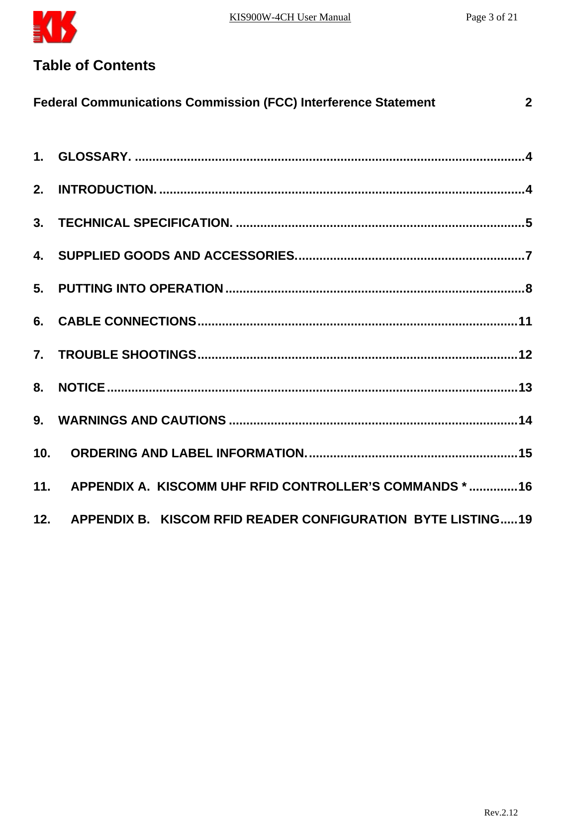
![KIS900W-4CH User Manual Page 12 of 21 7. TROUBLE SHOOTINGS Should the reader not work as desired, please check the following: a) Is the configuration of the reader as wanted? Check with help of the command W[w]. b) Is the configuration not known, are the baud rates of reader and terminal set different? Restore the basic setting of the parameters values with command D[d]. Now all parameter values are set to the default values, the reader will work in normal condition. c) Is the antenna defect or not properly connected? d) The transponder is not in the active antenna field. Bring the transponder closer to the antenna. e) Antenna mounting is wrong (for example behind a metal structure). In such a case, it can happen that the radiated power is reflected by unwanted plate in nearby metal structures. Please change antenna position. f) Although there is no transponder in the active antenna field. g) Noise from another radio equipment can also reduce the read range. You should try to remove all source of noise causing devices. Upper High Frequency fields radiated by other devices interfere with the reader communication: - power supplies, electrical motors, etc. Please remove such devices or remove the radiated interfering field by proper grounding if trouble takes place. Rev.2.12](https://usermanual.wiki/KISCOMM/KIS900W-4CH/User-Guide-554117-Page-12.png)
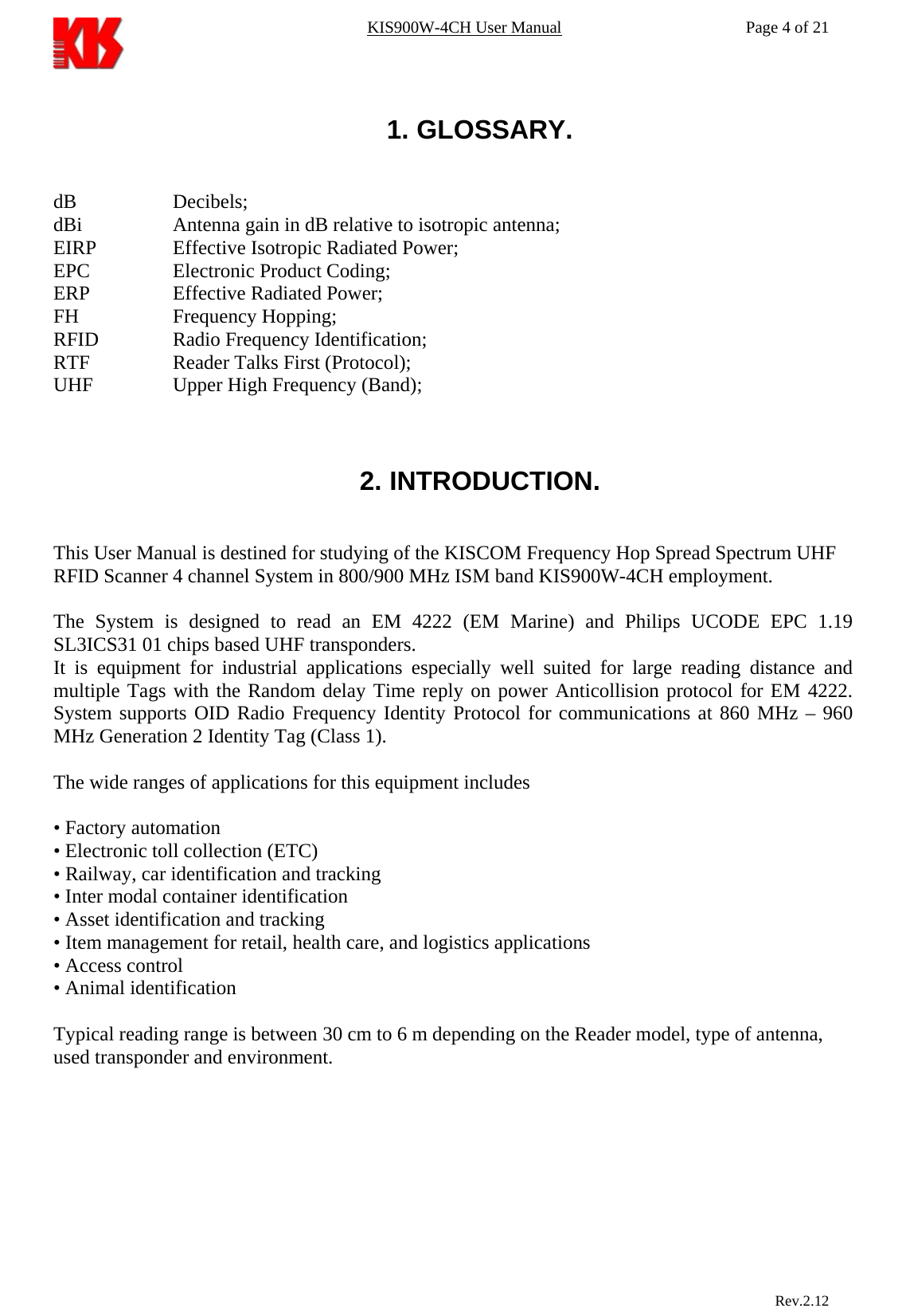
![KIS900W-4CH User Manual Page 16 of 21 11. APPENDIX A. KISCOM UHF RFID CONTROLLER’S COMMANDS * 1.1 Abbreviations Used hh = ASCII hex config byte number xx = ASCII hex value iiiiiiiiii = tag identification number [x] = alternative characters <cr> = Carriage Return $0D <lf> = Line feed $0A <ack> = Acknowledge $06 <nak> = Not Acknowledge $15 <sp> = Space $20 <SNR>= 8 bytes Serial Number -xxxxxxxxxxxxxxxx <ByteMask> 1 byte -xx BlockData> 4 bytes -xxxxxxxx WordData> 8 bytes -xxxxxxxxxxxxxxxx <Address> 1 byte -xx <CRC> 2 byte -xxxx <NAnt> 1 byte -xx 1.2 Base Commands After power on and successful self-test reader send a message: <KISCOM Reader 900RE Started><CR><LF> Default RS232 interface: 38400 baud, 8 data, no parity, 1stop bit 1.2.1. Command R[r] <cr> . Get number Tag from antenna in Continuous mode . In this mode only data reading adopted without errors Response <NAnt><iiiiiiiiiiiiiiii><CR><LF> ……………………………… <iiiiiiiiiiiiiiii><CR><LF> <iiiiiiiiiiiiiiii><CR><LF> <E>[P]<CR><LF> Repeating a “R” command during date entry aborts this command This command can be used in a mode “ of single reading tag” and mode “one answer per one time” For this case it is necessary to record 1 in fourth bit or to record 1 in fifth bit of byte of the configuration number 4, accordingly. Rev.2.12](https://usermanual.wiki/KISCOMM/KIS900W-4CH/User-Guide-554117-Page-16.png)
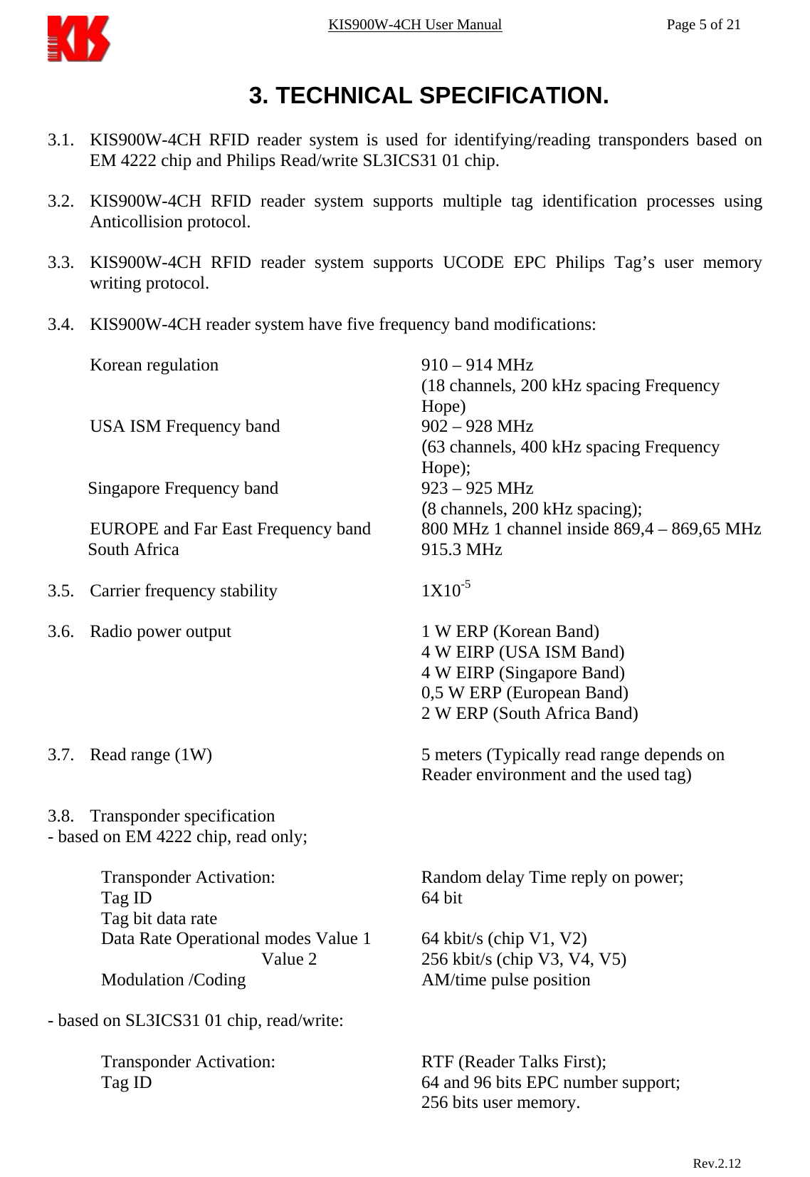
![KIS900W-4CH User Manual Page 17 of 21 1.2.2. Command V[w] <cr>. Firmware testing and check RFID system Response: <Korea Integrated Systems><CR><LF> <MultiProtocol RFID System ><CR><LF> <Model: USG3><CR><LF> <Firmware Version X.XX<CR><LF> <10.03.2005><CR><LF> <Checksum:____ ><CR><LF> 1.3. Extended commands. 1.3.1 Command L[l]hh xx Set the config byte "hh" in EEPROM to a value of "xx". Response <ack>xx<cr> Where "xx" is the value the config byte requested. 1.3.2 Command S[s]hh Get the ASCII hex value of configuration byte "hh" from the EEPROM. Response <ack>XX<cr> Where "xx" is the value the config byte requested. 1.3.3 Command D[d] Load the default ROM config values into RAM. Response <ack><Default settings!><cr><lf> <Air Link Interface: 40Kbit per second><cr><lf> <COM Interface: 38.4Kbits per second><cr><lf > <Korean Standard 910-914 MHz><cr><lf > Rev.2.12](https://usermanual.wiki/KISCOMM/KIS900W-4CH/User-Guide-554117-Page-17.png)
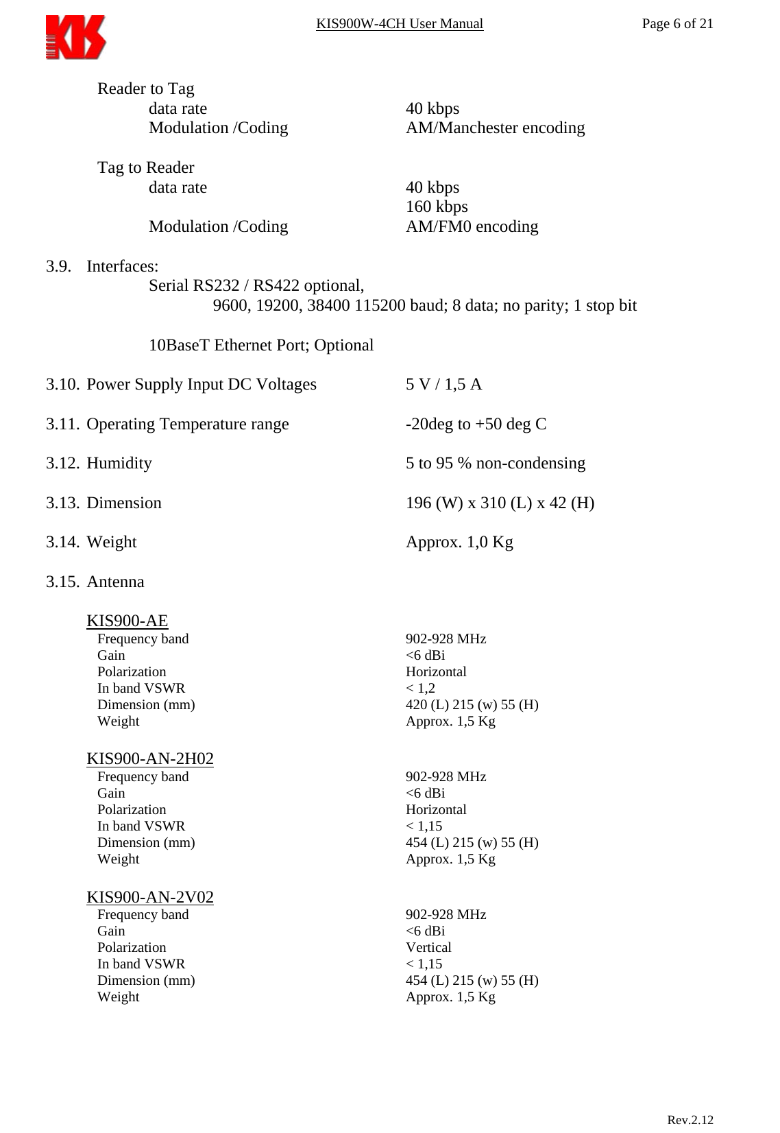
![KIS900W-4CH User Manual Page 18 of 21 1.3.4. Command W[w]<NAnt><SNR><Address><ByteMask><BlockData><cr>. Records 4 bytes of the data BlockData to the specified Address in a tag with number SNR The starting address for the WRITE command must be on a 4-byte page boundary. Executing WRITE, a tag only writes those bytes that are selected be the ByteMask. Response: 1 - <SNR><CRC><cr> - <xx><CRC><cr> - <Ok on write><cr> - <NAnt><BlockData><CRC><cr> 2 - <NAK><cr> 3 - <Error on synchro><cr> 4 - <Error on write><cr> 5 - <Error CRC><cr> 1.3.5 Command M[m] <NAnt><SNR><Address><cr> Reads the 8 byte memory content beginning at the specified Address and sends back its content in the response in a tag with number SNR Response: 1 - <NAnt><WordData><CRC><cr> 2 - <Error on synchro><cr> 3 - <NAK><cr> 1.4 Remote Access & Control Commands All described commands are activated at the installation necessary bits in config bytes. For application in this mode is necessary the connection of a embedded module LAN TCP/IP interface. Delivers by the order. * NOTE 1. This Command set is in force for KIS900W-4CH Sample S/W Version 28.02.2004. This Version S/W maybe used to reading EM4222 V3, V4, V5 with data rate 256 kbps. 2. Use KISCOM Demo software for sending Commands from PC to Reader. Rev.2.12](https://usermanual.wiki/KISCOMM/KIS900W-4CH/User-Guide-554117-Page-18.png)