KITCHENAID Garbage Disposal Manual L0912158
User Manual: KITCHENAID KITCHENAID Garbage disposal Manual KITCHENAID Garbage disposal Owner's Manual, KITCHENAID Garbage disposal installation guides
Open the PDF directly: View PDF ![]() .
.
Page Count: 5
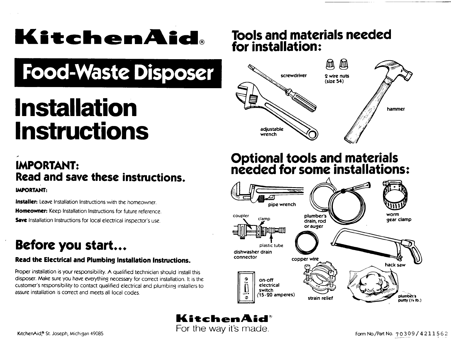
_[L J t c:h e nA_* d Tools and materials needed
® for installation:
Installation
Instructions
screwdriver
Optional tools and materials
IMPORTANT: needed for some installations:
Read and save these instructions.
IMPORTANT:
Installer: Leave Installation Instructions with the homeowner.
Homeowner: Keep Installation Instructions for future reference.
Save Installation Instructions for local electrical inspector's use.
Before you start...
Read the Electrical and Plumbing Installation Instructions.
Proper installation isyour responsibility. A qualified technician should install this
disposer. Make sureyou have everything necessaryfor correct installation. It is the
customer's responsibility to contact qualified electrical and plumbing installers to
assureinstallation is correct and meets all local codes.
pipe wrench
coupler plumber's worm
drain, rod gear clamp
plastic tube
dishwasher drain
connector
on-off
electrical
switch
(/15-20 amperes)
er _
copp hack saw
strain relief plumb_,'s
putty('/, lb.)
K_tchenAid, _ St. Joseph, Michigan 49085
I(itchen_kid _
For the way it's made. Form No./Part No. 7 0 3 0 9 /4211562
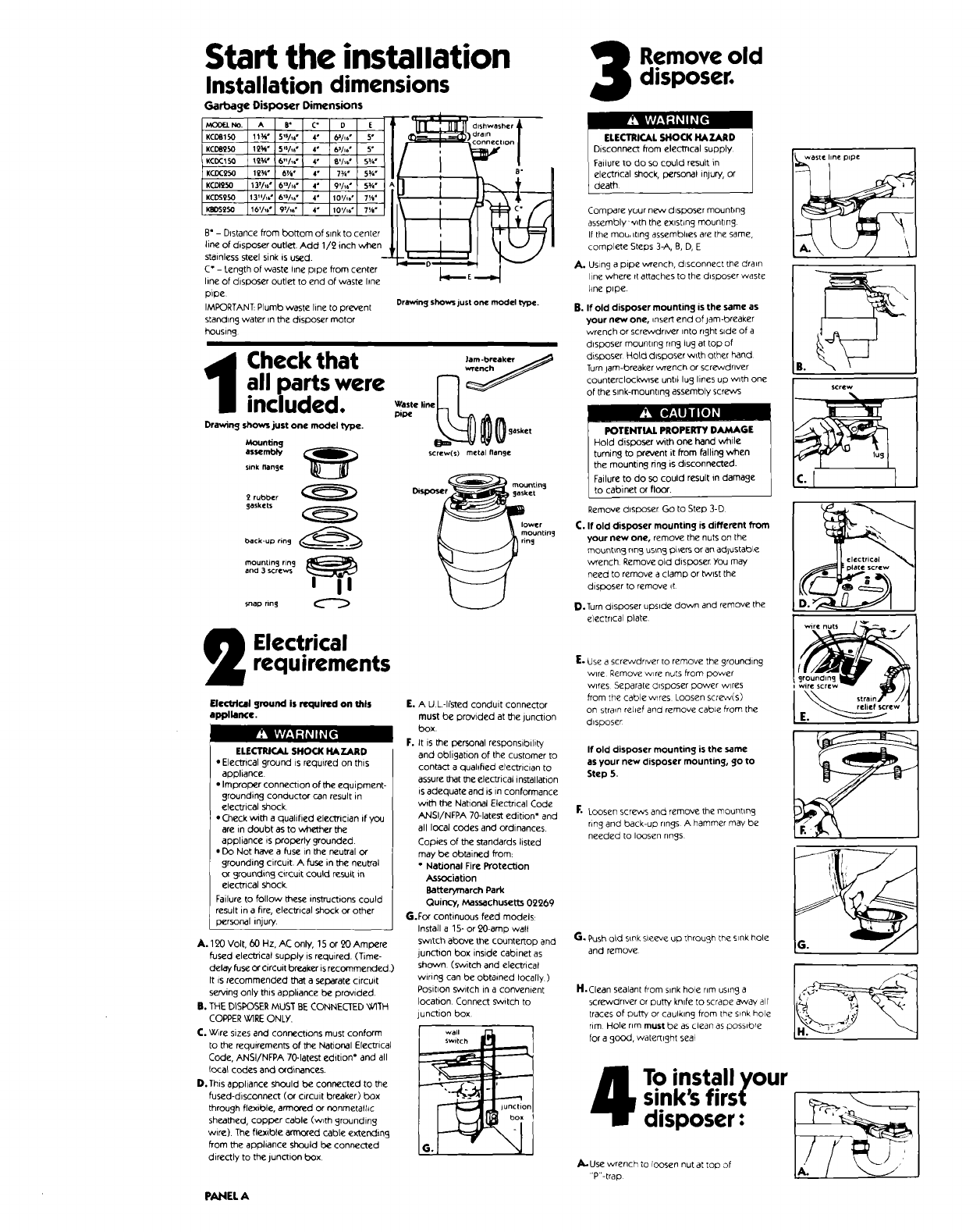
Start the installation
Installation dimensions
Garbage Disposer Dimensions
MOOr-LNO. A 8° C" D E
KCDB150 11_" 5_s/_6" 4" 6s/q6°5°
KcDa250 12_i* 5's/_" 4" 6s/_*5"
KCDC150 12_" 6"A," 4" 8'A_" 5¥,"
KCDC250 12_ ° 6VI°4" 7_" 5¥,"
KCDI250 13v/_6#613/16" 4" 9'/_" g_"
KCDS250 13"/_6"6_3/_6" 4" 10%B" 7_"
I_OSgSO 16V_6" 97/_6" 4" 10'/_6" 7V="
B" -Distance from bottom of sink to center
line of disposer outlet. Add 1/2 inch when ,
stainless steel sink is used.
C" - I.ength of waste hne pipe from center
line of disposer outlet to end of waste hne
pipe
IMPORTANT: Plumb waste line to prevent
standing water in the disposer motor
housing
,on! ,
Drawing shows just one model type.
Check that Jam .breakt_r
all parts were F]
included.
Mounting
assembly
sink flange
2rubber
gaskets
back-up ring
mountin S ring
and 3 screw
snap ring
Elect.rical
requirements
Electrical ground is required on this
appliance.
• * " F.
ELECTRICAL SHOCK HAZARD
•Electncal ground is required on this
appliance
•Improper connection of the equipment-
grounding conductor can result in
electrical shock.
• Check with a qualified elecmcian if you
are in doubt as to whether the
appliance is properly grounded.
•Do Not have a fuse in the neutral or
grounding circuit. A fuse in the neutral
or grounding circuit could result in
electrical shock.
Failure to follow these instructions could
result in a fire, elec_ical shock Or other
personal injury.
A. 120 Volt, 60 Hz, AC only, 15 or 20 Ampere
fused elec'_ical supply is required. (Time-
delay fuse Orcircuit breaker is recommended.)
It is recommended that a separate circuit
serving only this appliance be provided.
B. THE DISPOSER MUST BE CONNEC'[ED _._TH
COPPER WIRE ONLY.
C. Wire sizes and connections must conform
to the requirements of the National Elec_-ical
Code, ANSI/NFPA 70-latest edition* and all
(peal codes and Ordinaries.
D. This appliance should be connected to the
fused-disconnect (or circuit breaker) box
through flexible, armored or nonmetalhe
sheathed, copper cable (w_th grounding
wire). The flexible armored cable extending
from the appliance should be connected
directly to the junction box
E. A U L-h'sted conduit connector
must be provided at the junction
box.
It is the personal responsibility
and obligation of the customer to
contact a quahfied electhcian to
assure that the electrical installation
is adequate and iS in conformance
with the National Electrical Code
ANSI/NFPA 70-latest edition" and
all local codes and Ordinances.
Copies of the standards listed
may be obtained from:
* National Fire ProtecUon
,_ssociation
Batterymarch Park
Quincy, Massachusett_ 02269
G.For continuous feed models:
Install a 15- or 20-amp wall
s_vltch above the countertop and
junction box inside cabinet as
shown. (switch and electrical
wiring can be obtained locally)
Posit_on switch in a convenient
location Connect switch to
unction box
Go_ _
PANEL A
Remove old
disposer.
Compare your new disposer mounbng
assembly '-.'_th [he existing mounting
If the mou, itlng assembhes are the same,
complete Steps 3-A, B, D, E
A. Using a pipe wrench, disconnect tJ_edra_n
line where rtattaches to the disposer waste
hne pipe.
B. if old disposer mounting is the same as
your new one, _nsert end of jam-breaker
wrench or screwdriver into fight side of a
d_sposer mounting nng lug at top of
disposer Hold d_sposer w_th other hand
Turn jam-breaker wrench or scr_drlver
:ounterclock'vv_se until lug lines up with one
_fthe sink-mounting assembly screws
POTENTIAL PROPERTY DAMAGE
Hold disposer with one hand while
turning to prevent it from falling when
the mounting ring is disconnected.
Failure to do so could result in damage
to cabinet or floor.
Remove disposer Go to Step 3-D
C. If old disposer mounting is different from
your new one, remove the nuts on the
mount_n_ nng us_n_ pher_ or an adjustable
wrench Remove old disposer You may
need to remove a clamp or bNist the
disboser to remove it.
P.Turn disposer upside down and remove the
electrical plate
E. Use a screwdrrver [o remove the grounding
wire Remove wire nuts from power
wires Separate d_sposer Dower wires
from the cable wires Loosen screw(s)
on strain reLief and remove cable from the
disposer
If old disposer mounting is the same
as your new disposer mounting, go to
Step 5.
_- Loosen ser_s and remove the moun_mg
ring and backIU D rings A hammer may be
needed to loosen rings
G. Push Od s_nksleeve uD through the s_nkhole
and remove
H.Clean sealant from sink hole rim using a
screwdriver or putty knife tO scrape _ay air
tracesof put_ or caulking from [he s_nk hole
rim Hole nm must be as clean as poss_bre
for a good, watertight seal H'_"-_ _1
To install yoursink's first I
disposer:
/_ U_e_pnCh to loosen nutat top of

II. Remove nut at top of sink strainer Remove
extengon p_pe
C. Loosen the large-dlameter nut at the base
of the strainer by placlng the tip of a
scr_'\Ndnver on the ridge of the nut and
gently tapplng [he screwdrlver wlth a
hammer
D. Remove nut
G. Push the strainer assembly up through the
sink hole and remove. E°
Clean sink's
dram hne.
If installing in a new home, go to Step 6
Remove drain trap. Using an auger, c dan out
the honzontal drain pipe that runs from the
trap to the main waste pipe.
Separa.te the
mounting
assembl
_1_ Holding the mounting assembly with one-
hand, use the Other hand to insert tam-
breaker wrench into one of the rugs of the
lower mounting ring Turn assembly counter-
clo_k'wlse and remove.
B. Loosen screws on mounting assembly until
they are level with mounting nng surface
"'O
th_ after routin
|
mounting,_j j lower
assembly mounting
)
J mounting rln_
Working from under sink, shp the second
rubber gasket, then the metal back-up nng
(flat side up), up and over sink flange
Attach the J'
u00 ,.
mounting .t.,
assembly.
II. Holding the rubber gasket and metal back-
up ring in place, attach the mounting ring to
the sleeve with the three mounting nng
screws Do No[ tighten screws at thrs time.
C. Push rubber gasket, metal back-up nng and
mounting ring further up sink sleeve Slide
snap ring onto sink sleeve until it pops into
place in the sleeve groove.
D. Tighten mounting screws until entire
mounting assembly is seated evenly and
t_ghtly against sink.
/.; f _- _- t
!
M ke
electrical
connections.
Remove electncaJ plate from the bottom
of the new disposer Pull out the black and
white elec_ical wires. Locate the green
grounding screw under plate
R. Insert strain relief into hole Insert power
supply cable through strata rebel Pull cable
wires through opemng where disposer
wires are located Tighten strain rehef
SCre'v'_
C. Connect power supply cable wire's to [-he
i disposer wires uslng elecl]-ical wire nuts or
by soJdering wlres tc_jL_her Be sure to
connect white to whi_, and black to
black. Wrap wire connections with
electncal tape Put wires back inside
disposer housing Note: This appliance is
equipped with copper lead wires. If
connection is made to aluminum house
wiring, use only special connectors which
are approved for joining copper to
aJuminum wires m accordance with the
national electncal code and local codes
and orcllnances
_. Use screwdriver to pry off snap ring
D. Take assembly apart and set aside
snap ring _
sleeve
L_" _ --3'_ nng j
Apply rubber
gasket or putty
to sink flange.
The rubber sink flange gasket should always
be used where possible Place rubber
gasket over s_nk flange Go to Step 7-C
B. If sink opening does not permit the use of a
rubber seal, plun_ber_ putty may be used
Form putt'/_nto a long roll by rolhn3 _t
between your hands Press roll under sink
flange rim
C. place flange tnto sink dram hole Push down
gently but firmly, to make sure flange stts
evenly over gasket or m putty
Pad,IF.J.B
10Check for proper grouncling.
I
ELECTRICALSHOCK HAZARD
Elec_ical ground is required on this product I
Iml_oper connexion of the equipment 9rounding condudot I
can resutIne ectT cal shock, personal injury, or death
Electrical ground is required on this
appliance.
DO NOT reconnect electrical current to
main service panel until proper ground
is ir.stalled
A. If the cabl_ leading to the disposer has
three wires, a_ach the green grounding
w_re to the green grounding screw Go to
Step lO-O
B. If the cable ClOdSNOT have a grounding
wire, a_ach a ,ength of copper wire (no
smaller than the o_her cable w_re) to the
_een grounding screw
C. A_ach the other end of the groundrng wire
to a grounded metal cold water pipe"
DO NOT ground to a gas supply line or
hot water supply line.
L,se grounding camp to Secure w_re to
,C'De if non-indi!! or plastic pipe is used _n
,'_ater connections or water supply, you must
_ave a auahfled e!ectnclan install a proper
qround
"Grounded ¢OIC_ _a_er O_Pe mus_ have metal
r'_?rqJored by D _sbc, rubber or omer electrical
-'_ _- ,'_ cor _('c'o,s SuC_ as _OSeS "t' rigs.
_ater
pipe
p
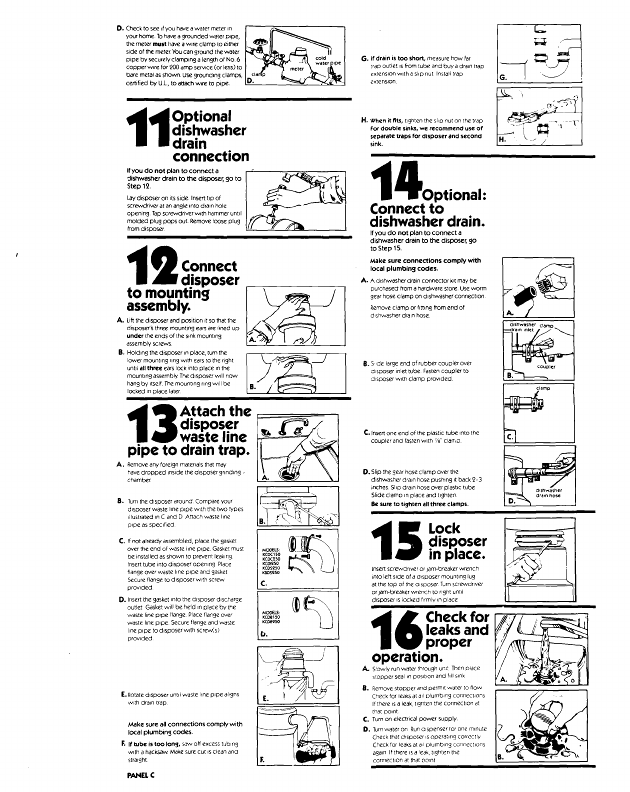
O,Checktoseeifyouhaveawatermeterin I_ 1
your home 1"0have a grounded water p,pe, I II _ I
the meter mull have a wire clamp tO either I"_ II _ _ I
sideofthemeterYoucangroundthewater _ _ ..111 I
pipe by securely clamplng a length of No 6 I _ _1 cold . !
copperw,re,or'_00am0se_,ee<or,ess_toI _ °e';'\'°_i&""I
baremeta'asshow"U*grou°d'ng¢'°m_'Io:'_°__-----_1
certified by U.L., to attach wire to pipe.
A.
e.
td Optional
I dishwasher
m drain
connection
If you do not plan to connect a
dishwasher drain to the disposer, go to
Step 12.
Lay disposer on its side. Insert tip of
screwdriver at an angle Into drain hole
opening. Tap screwdriver with hammer unttl
molded plug pops out. Remove loose plug
from disposer
i!
2 Connect
disposer
to mountmg
assembly.
Lift the disposer and position it so that the
disposer _ three mounting ears are lined up
under the ends of the sink mounting
assembly screws
Holding the disposer _nplace, turn the
lower mounting ring with ears to the right
until all three ears lock into place in the
mounting assembly The disposer wdl now
hang by itself. The mounting nng will be
locked in place later
Ao
B°
disposer
waste line
pipe to drain trap.
Remove any foreign materials that may
_aVemdrhOrpped inside the disposer grind,rig ,
(I I
Tun roun
disposer waste line pipe with the _vo types
diustrated in C and D Attach waste hne
pipe as speQfied I
C. If not already assembled, place the gasket II_.
over the end of waste line pipe. Gasket must _E!.s:
be installed as shown to prevent leaking KCDC15a
KCDC250
rnsert tube into disposer opening Place KC81250
KCDS250
flange over waste line pipe and gasket s2so
Secure flange to disposer wtth screw
provpded
D. Insert the gasket into the disposer discharge l__c'c_l_
[
outlet Gasket wil! be held in place by the
waste line pfpe flange Place flange over _{:)[LS:
waste hne pipe Secure flange and waste
hne pipe to disposer with screw(s)
prowded
E. Rotate disposer untd waste hne pipe aligns
with drain trap
jr
Make sure all connections comply with
local plumbing codes.
F. If tube is too long, saw off excess tubing
with a hac_ Make sure cut is clean and
straight
PANEL C
G. If drain is too short, measure how far
Irap outlet is from tube and buy a drain trap
extension with a slip nut Install trap
e×_enslon
H. When it fi_, hgnten the sho nut on [he trap
For double sinks, we recommend use of
separate traps for disposer and second
sink.
4Optional:
Connect to
dishwasher drain.
If you do not plan to connect a
dishwasher drain to the disposer, go
to Step 15.
Make sure connections comply with
local plumbing codes.
A. A dishwasher drain connector I(l[ may be
purchased from a hardware store. Use worm
gear hose clamp on dishwasher connection
Remove clamp or fitting from end of
d_shwasher drain hose
R. S,de large end of rubber coupler over
disposer inlet tube Fasten coupler to
disposer with clamp provided
C. Insert one end of the plastic tube into the
coupler and fasten with 7/8"clalT,D.
dishwasher c_amo,_
l_ler
O. Slip the gear hose clamp over the
dishwasher dra_n hose pushing It back _2-3
inches. Shp dra]n hose over plastic tube
Slide eFamo m place and tighten
Be sure to tighten all three clamps.
5 Lock
disRoser
in pmace.
Insert screwdriver or jam-breaker wrench
into left 51c_eof a Chsposer mounting lug
at the top of the aisposer Turn scre'wdrlver
or jam-breaker'wrench to right untd
disposer" is locked firmly in place
1_ Check for
I_ leaks and
proper
operation.
S!owly run water _hrough unit Then place
s!opper seal in posibon and fill sink
B, Remove stopper and permit water [o flow
Check for Jeaks at all plumbing connections
If there is a leak, [_gn[en the connection at
t_'at pomt
C. Turn on electTical power supply.
D. Turn water on Run Clspenser tar one mff_ute
Check that d_sposer is operating correcIly
Cheek for leaks at a,I plumbing connechons
again If there is a !eak, tighten the
connection at that oornl
f Instructions pertaining to risk of
ire, electric shock, or injury to persons.
Important safety
instructions"
ELECTRICAL SHOCK AND PERSONAL
INJURY HAZARD
When using electric appliances, basic
precautions should always be followed,
including the following:
1. Read all the instructions before using
the appliance.
2. To reduce the risk of injury, close
supervision is necessary when
appliance is used near children.
3. Do not put fingers or hands into waste
disposer.
4. Turn the power switch to the OFF
position before attempting to clear a
jam or remove an object from the
disposer.
S. When attempting to loosen a jam in a
waste disposer, use a self service jam-
breaker wrench as described in Use
and Care Guide.
6. When attempting to remove objects
from a waste disposer, use long-
handled tongs or pliers.
Failure to follow these instructions could
result in electrical shock, personal injury
or death.
©1991 KJtchenAid, Inc.
Form No./Part No. 70309/4251562
7. To reduce the risk of injury by materials
that may be expelled by a food-waste
disposer, place the stopper in the
drain/grind position when grinding Do
not put the following into a disposer:
a. Clam and oyster shells.
b. Drain cleaner
c. Glass, china or plastic.
d. Large, whole bones
e. Metal, such as bottle caps, tin cans,
or aluminum foil.
8. When not operating a disposer, leave the
drain cover in place to reduce the risk of
objects falling into the disposer.
9. Before pressing red reset button, be
sure the wall switch is in the off
position and on batch feed models
remove the stopper from the run
position.
10. a. GROUNDING INSTRUCTIONS FOR
CORD-CONNECTED UNITS. This
appliance must be grounded. In the
event of a malfunction or breakdown,
grounding provides a path of least
resistance for electric current to
reduce the risk of electric shock If this
appliance is equipped with a cord
having an equipment-grounding
conductor and a grounding plug, the
plug must be plugged into an
appropriate outlet that is property
installed and grounded in accordance
with all local codes and ordinances.
For service information, call toll-flee 1-800-422-1230
Prepared by KiEchenAtd, ° St Joseph, Michigan 49085
b.
ELECTRICALSHOCK HAZARD
Electrical ground is required on this
appliance. Improper connection of the
equipment-grounding conductor can
result in a riskof electric shock or death.
Check with a qualified electrician or
serviceman if you are in doubt as to
whether the appliance is properly
groundeo. Do not modify the plug - if
it will not fit the outlet, have a proper
outlet installed by a qualified
electrician.
GROUNDING INSTRUCTIONS FOR
PERMANENTLY CONNECTED UNITS:
This appliance must be connected to
a grounded, metal, permanent wiring
system; or an equipment-grounding
conductor must be run with the circuit
conductors and connected to the
equipment-grounding terminal or lead
on the appliance.
Save these
instructions.
INSTALLER- Please leave Installation
Instructions with the homeowner or
occupant.
Printed in U.S A.
