KODICOM SHR5016 Digital Video Recorder User Manual users manual
KODICOM CO., Ltd. Digital Video Recorder users manual
KODICOM >
users manual

DIGITAL
RECORDING SYSTEM
SHR SMART VIEW Userguide
THIS DEVICE COMPLIES WITH PART 15 OF THE FCC RULES. OPERATION IS
SUBJECT TO THE FOLLOWING TWO CONDITIONS: (1) THIS DEVICES MAY NOT
CAUSE HARMFUL INTERFERENCE, AND (2) THIS DEVICE MUST ACCEPT ANY
INTERFERENCE, RECEIVED, INCLUDING INTERFERENCE THAT MAY CAUSE
UNDERSIRED OPERATION.
Note : This equipment has been tested and found to comply with the
limits for a Class B digital device, pursuant to part 15 of the FCC Rules.
These limits are designed to provide reasonable protection against
harmful interference in a residential installation. This equipment
generates, uses and can radiate radio frequency energy and, if not
installed and used in accordance with the instructions, may cause
harmful interference to radio communications. However, there is no
guarantee that interference will not occur in a particular installation. If
this equipment does cause harmful interference to radio or television
reception, which can be determined by turning the equipment off and
on, the user is encouraged to try to correct the interference by one or
more of the following measures :
- Reorient or relocate the receiving antenna.
- Increase the separation between the equipment and receiver.
- Connect the equipment into an outlet on a circuit different from that
to which the receiver is connected.
- Consult the dealer or an experienced radio/TV technician for help.
NOTE: THE MANUFACTURER IS NOT RESPONSIBLE FOR ANY RADIO OR TV
INTERFERENCE CAUSED BY UNAUTHORIZED MODIFICATIONS TO THIS EQUIPMENT.
SUCH MODIFICATIONS COULD VOID THE USER'S AUTHORITY TO OPERATE THE
EQUIPMENT.

This is a user guide for SHR Smart System.
This guide gives you SHR Smart System’s external spec, name, PAN/TILT Control, the way of
attaching peripheral devices and configuration.
・ The copyright of this manual belongs to Samsung.
・ It is prohibited to copy this manual without permission.
・ Any damage or break owing to carelessness is out of our warranty service.
・ Should you need open the system for extention or repairing, it is recommended that you ask
for an engineer’s assistance by contacting the dealer you bought it or Samsung.
・ This product has certification for domestic and industrial use. Also, it has taken CE for Europe,
FCC for the U.S.
NOTICE
NOTICE

【 Please check these out before using the system.】
Avoid any place that has high moisture, dust or black dirt.
Avoid any place that has direct sun light or heat. High temperature is not good for the product.
Keep product away from a electric shock or magnetic substance.
Avoid high or low temperature.(Recommended temperature is 5 °C ~35°C)
Be careful not to drop any conducting material into the ventilation hole.
Turn off the system before installation.
Ensure enough space for the cables at the rear of the system.
Avoid any place that may shake the product.
Use the product in areas where it ventilates well.
Radio, TV or Radio devices might be harmful to the system.
Don’t disassemble the system on your own.
Do not put any heavy objects on top of the product.
This device designed to operate under Max. 40℃. When you install this device in the rack,
please consider the Max. ambient temperature. Please install this device Proper ambient
temperature of all park.
CAUTION : When you install this device in the rack, the operating ambient temperature may be
greater than room ambient. Please consider this condition and simulate the Max. Temperature
and install in an environment Compatible temperature.
Reduced Air Flow : Installation of this device in a rack should be such that the amount of air
flow required for safe operation of this device is not compromised. Please provide enough
space to get the proper air flow.
Mechanical Loading – Mounting of this device in the rack should be such that a hazardous
condition is not achieved due to uneven mechanical loading.
Circuit Overloading : Please read the rating in the nameplate and consider appropriate power
supply and supply wiring.
When you are using like a power strips except direct connections to the branch circuit, please
make sure to connect reliable earthing maintained.
Notice before installation
Notice before installation
CAUTION
CAUTION : Danger of explosion if battery is incorrectly replaced. Replace
Only with the same or equivalent type recommended by the manufacturer.
Dispose of user batteries according to the manufacturer’s instructions”
Product Contents
Product Contents
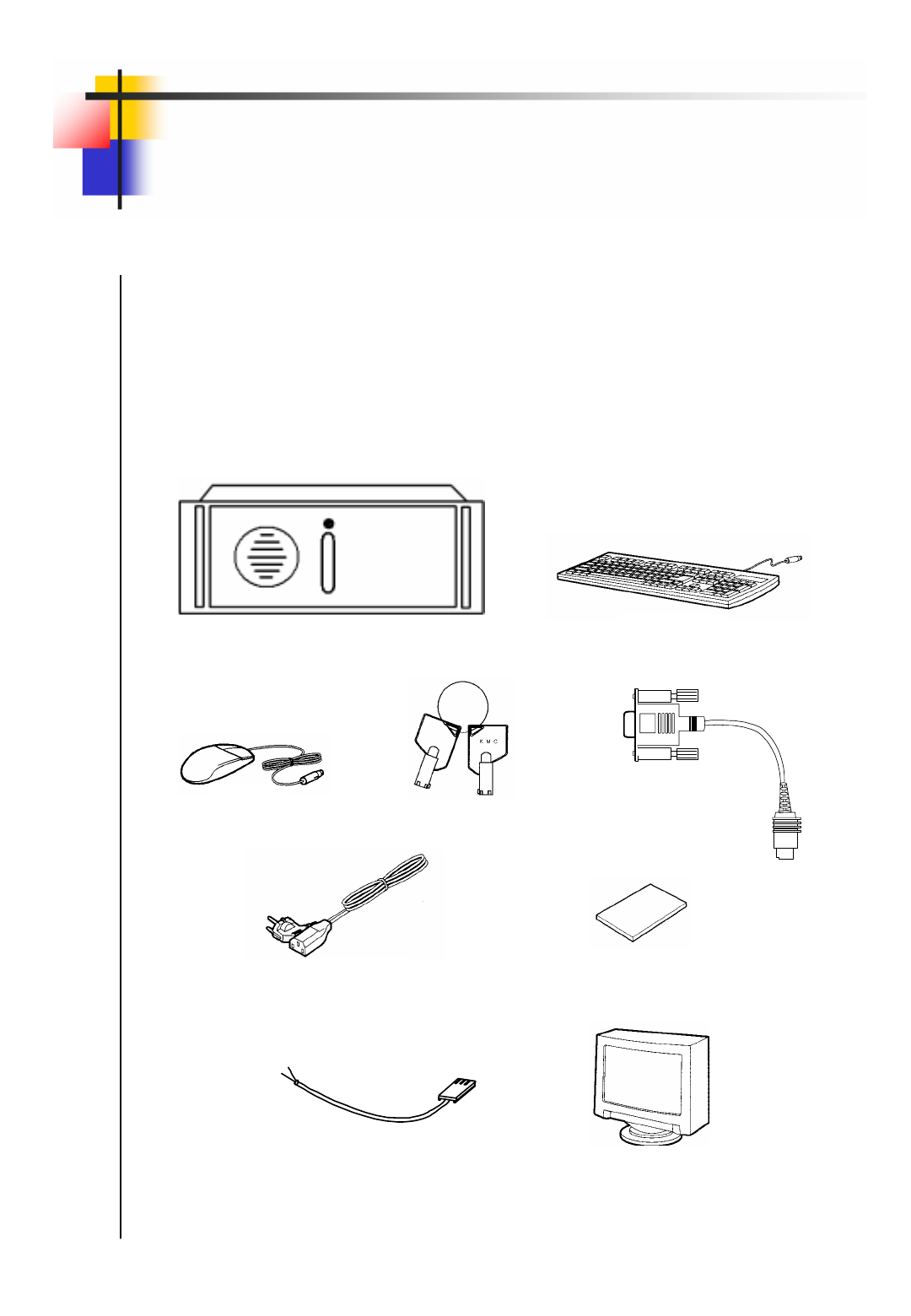
【Check to make sure the box has everything below. 】
Contact your dealer if there is any missed item.
(Optional: Monitor- Recommended monitor is one that supports the resolution of at least
1024*768, 60Hz)
SHR SMART SYSTEM Key Board
Mouse
Power Cable User guide
Key
Monitor(Option)
Communication conversion cable
( used for PAN/TILT CAMERA )
Serial Port Cable

Contents
6I. Multi channel Video Surveillance
1. Mainscreen
72. Screen Division
83. State screen
11 4. Emergency Recording, Alarm off, Setup,
Search, Power
12
14 II. Environment Setup
1. Hardware
15 2. System
21 3. Camera/Audio record
33 4. Schedule
35 5. Motion detection
39 6. Network
41
45 III. Search Screen
1. Execute Search Program
46 2. Search Date and Time Selection
47 3. Select Camera
48 4. Playing Recording
49 5. Search Tool
52
7. Data Backup
54 6. Audio Setup
53
8. Print Search Screen
65
IV. Appendix
1. Manual ISDN Setup without router
68 2. Formatting a CD using Direct CD
72 3. System setup for Audio function
74 4. Serial cable connection (input)
79 5. PAN/TILT Drive connection
80
□Warranty Guide
82
6. External Sensor input and Control
output connection
81
67
5. PAN/TILT Mode
13

6
6
I.Multi channel Video Surveillance
7
7
1
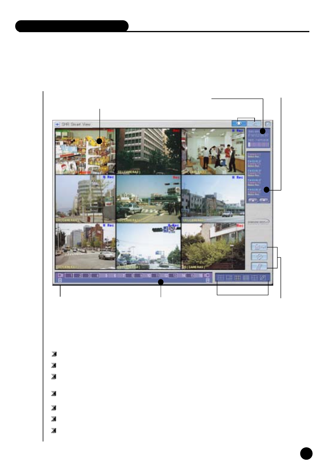
Mainscreen
Screen
Division
button
FunctionSelect
기능선택 버튼
System Status
Division
Camera/Sensor/Alarm
/Audio
State Screen
Description
Screen Division : Displays the selected camera image
System Status : Display time/date, HDD usage.
Screen Division : Select the live image under surveillance. Maximum 16 live image can be
displayed (1, 4, 6, 9, 16 division, 4division rotation mode)
State Screen : Display for the status of continuous recording, sensor, alarm, motion, audio or
network
Function Select : Emergency recording, alarm off, configuration and displaying recorded image
Camera/Sensor/Alarm : Display status of camera recording, sensor/alarm and audio.
Alarm/Sensor/Audio
togglebutton
Alarm/Sensor/Audio : Toggle for display and control of alarm/sensor/audio in rotation.
I. Multi channel video surveillance

8
8
2
Screen Division
Screen division can be done by 『Screen Division』button
REC
Camera name
PAN/TILTPTZ camera display Recording status
Screen Division
Camera : Display the position of the camera under surveillance.
The default value is 1[POSITION1]. But you can modify it in setup.
Recording Status : Display recording status of each camera.
For continuous recording in red “Rec”, and for motion detection recording in
blue “M Rec” and nothing for no recording.
PTZ camera display : When the installed camera is PAN/TILT, displays green “ PAN/TILT”

9
9
Screen Division
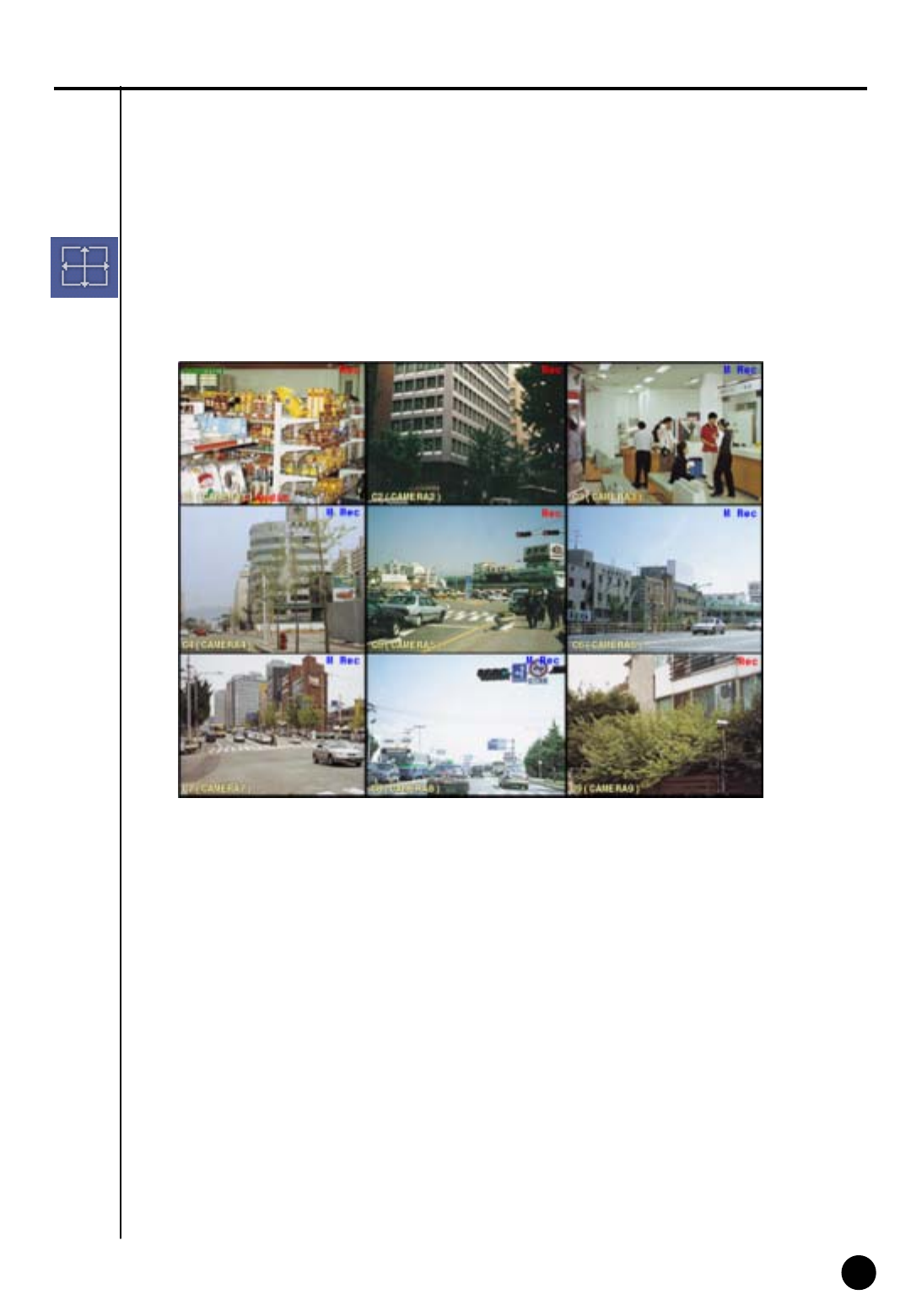
4ch 6ch 9ch 16ch full screen rotation
Division
How to operate
① Click the division button you want.
② Divided screen will appear.
・ Screen division can be made in 4, 6, 9, 16, full screen and quadrotation.
・ Any click on certain camera will give you full screen.
Rotation by 4ch
・ Display in 4ch by rotating
・ Click on screen division button to exit this mode.
Full screen mode
・ Left click on certain image under divided screen will give you full screen of the camera.
・ Clicking again on the full screen will give you previous divided screen.
10
10
Full screen display
・ Full screen mode of divided screen.
・ It will look as below.
Exiting Full screen display
・ To go to previous mode from “full screen display” press right click.
11
11
3
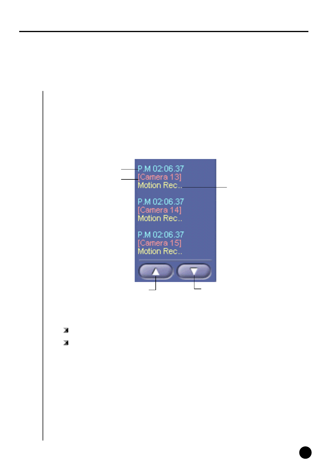
State screen
・ Display the status of event such as continuous recording, sensor, alarm, motion, audio or
network connection.
・ State screen displays 『 time of event - camera number – event type』
State screen
Time of event
Camera number Event type
Above Event Below event
Camera number : Displays the current camera number in order.
Event movement : Use this button to move up and down to see other event
12
12
4
Emergency Recording, Alarm off, Setup,
Search, Power
① You can start recording regardless of recording schedule while monitoring live image.
② All the installed cameras start recording together and ”REC” appears on screen.
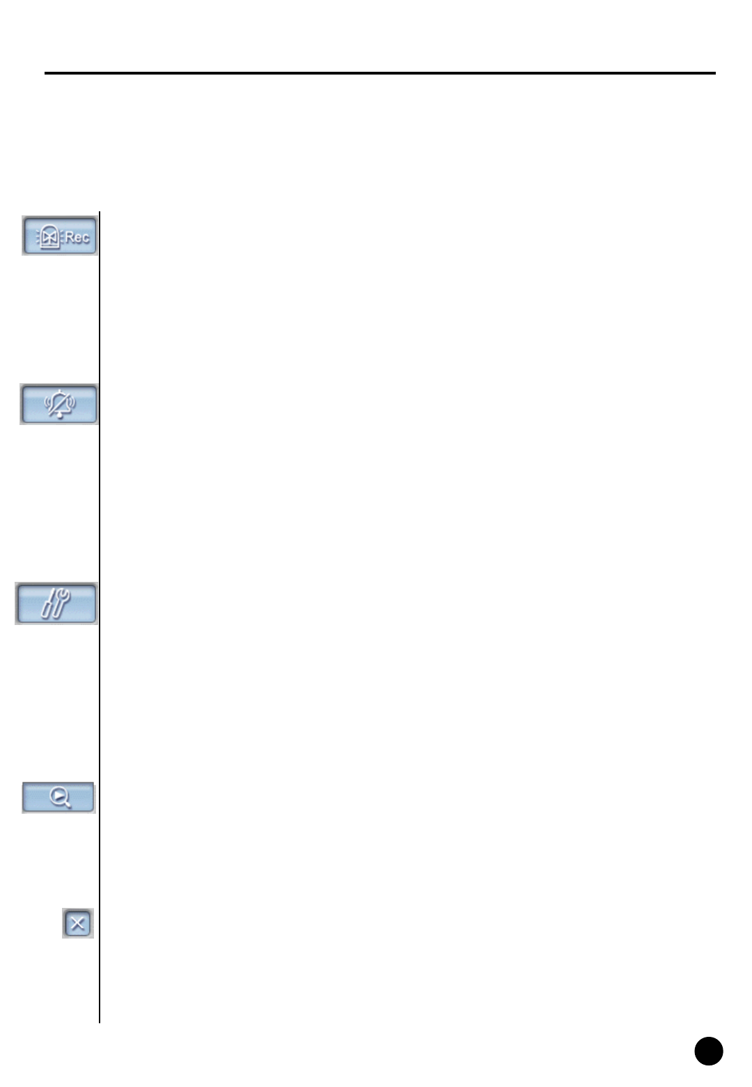
Emergency Recording
③ You can stop emergency recording by clicking once more.
④ Recording term is normal term on each camera’s setup.
Alarm off
① Stops alarm signal
② Alarm output can be used together with sensor or motion detection and the output
duration is adjustable.
③ Press “OK” button to save adjusted configuration. Press “Cancel” button to cancel the adjusted
configuration.
④ Password can be used to make it secure.
▶ When the button is pressed on : Alarm output is impossible or alarm output
is on halt
▶ When the button is not pressed : Alarm output is possible
Setup
① Click on this button will bring up setup window.
② Setup windows consist of six windows.
Search
① Click on this search button execute search mode
② This is used to search recorded data and recording and monitoring is possible during search.
Power
① Use this to power off the system.
② Password can be used to make this function secure.
13
13
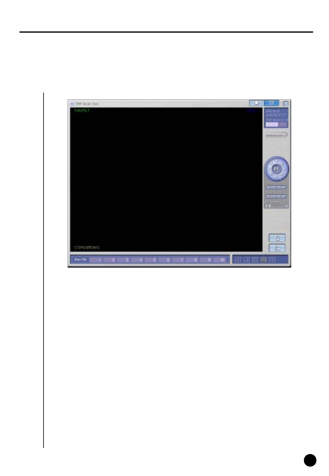
5
PAN/TILT Mode I–Speed Dome
❶
❷
❸
❹
❺
❻
❼
❽
❾
Feature
Display current date and time
PAN/TILT : controls camera in left and right / up and down / diagonally adjust it
FOCUS : adjust focus of the camera lens.
(not applied to AUTO FOCUS lens)
ZOOM : adjust Zoom In/ Zoom Out of the camera
P/T Speed : adjust Speed Dome camera’s movement speed
PreSet setup : PreSet setup for Auto PAN/TILT function
❶
❷
❸
❹
❺
❻
❼
❽
Auto Preset : Camera tours automatically along the configured path. Up, down or left,
right button cane stop auto function.
PAN/TILT number : You can move camera toward the position recorded.
Display mode : convert from PAN/TILT mode to Live display mode
❾
14
14
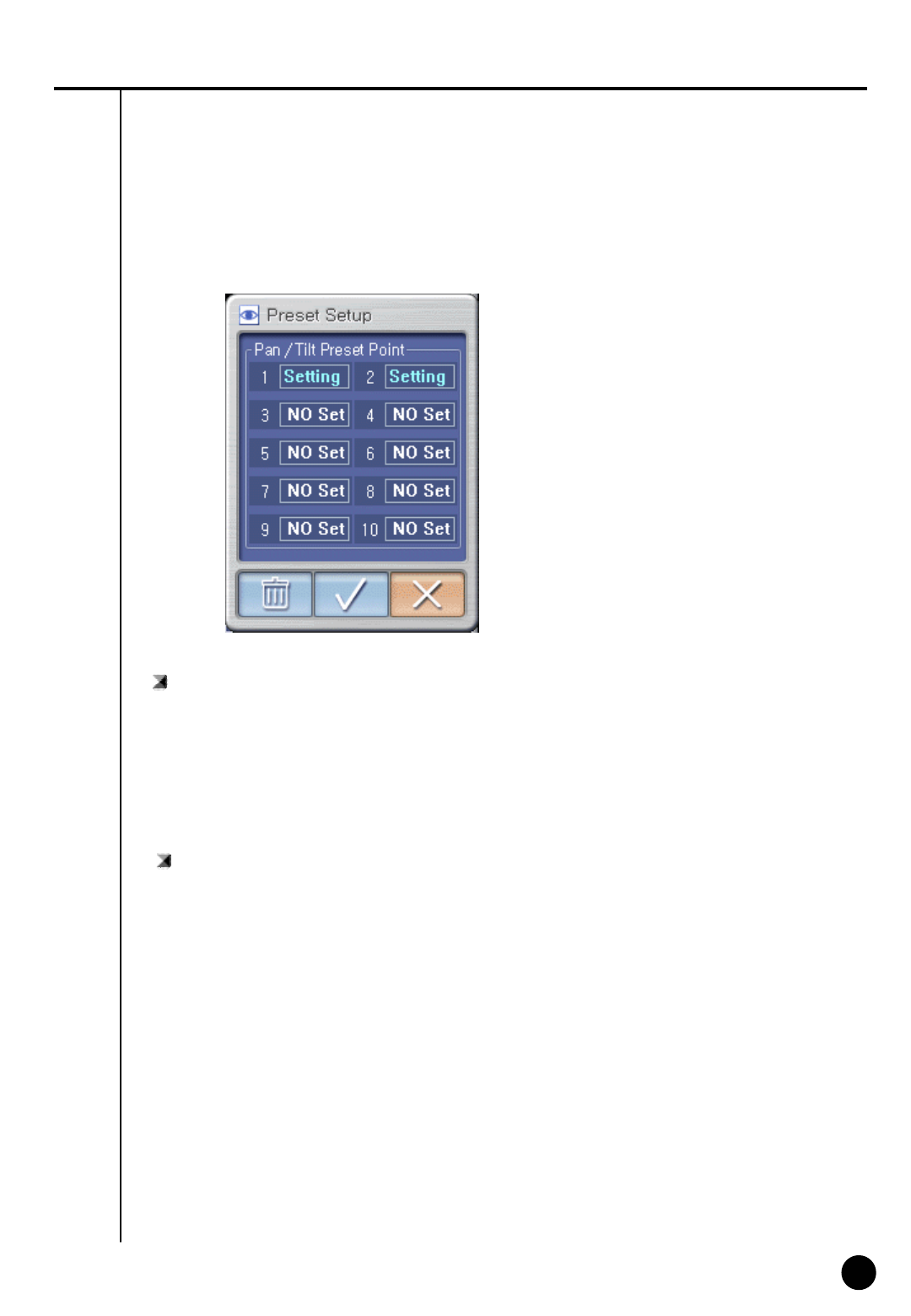
How to PreSet
How to Preset
: Location of camera can be appointed from 1 to 10
① Change the camera direction to anywhere you want
② Select Preset number
③ Select “9”
(It will convert from “Setting” to “No Set” and location of Preset will be specified).
How to delete Preset
: Delete the specified Preset location
① Select any Preset number you wish to delete
② Select trash can picture icon
(It will convert from “No Set” to “Setting” and you can relocate preset location.)
15
15
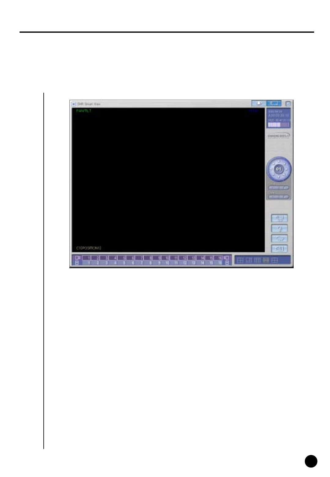
6
PAN/TILT Mode II –RX (Already Setup)
Description
Indicates current date, day, and time
Auto PAN : On/Off Function for Auto PAN Camera
LIGHT : On/Off function for Camera light
❶
❷
❸
❹
❺
❻
❼
❽
❾
❶
❷
❸
❹
❺
❻
❼
❽
WIPER : It operates camera’s wiper
POWER : To On/Off camera’s Power
❾
☞AutoPAN, LIGHT,WIPER,POWER button may be indicated differently based on the type of
RX Receiver.
(It is because different manufacturer have different functions to support each).
Display mode : convert from PAN/TILT mode to Live display mode
ZOOM : adjust Zoom In/ Zoom Out of the camera
FOCUS : adjust focus of the camera lens.
(not applied to AUTO FOCUS lens)
PAN/TILT : controls camera in left and right / up and down / diagonally adjust it

16
16
II. Environment Setup
17
17
1
Hardware
Ⅱ. Environment Setup
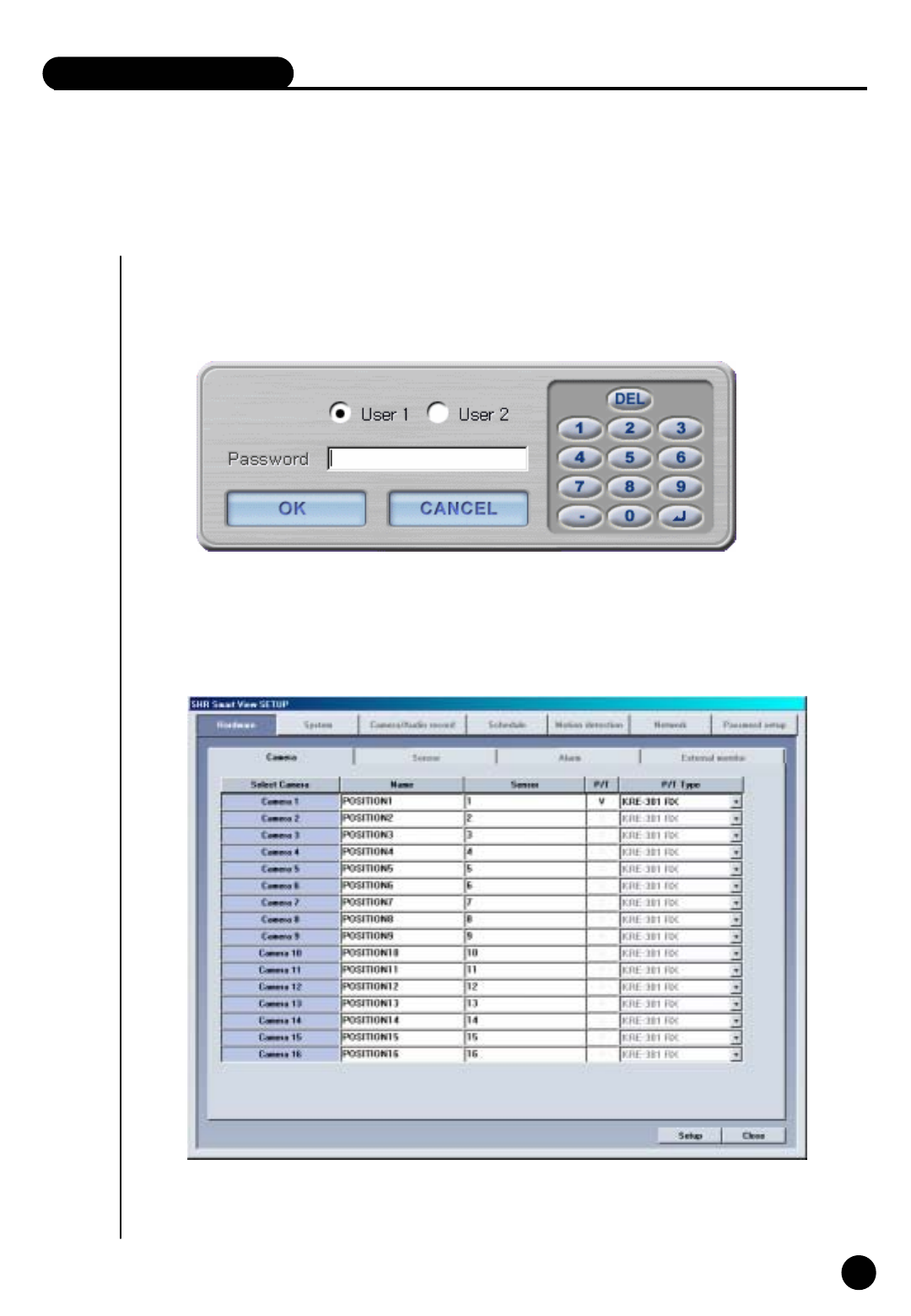
Hardware [Camera]
① Press set up button for system setup
② Screen to input password will appear for system securing purpose.
If the password was not created initially, then just click [ok].

18
18
Description
Select Camera: To decided which camera to use
Name
: Input the name of place which the camera will be installed
Sensor
: Input the sensor number which will be used with each camera
P/T
: Check if the selected camera is PTZ.
In this case, PTZ related equipment should be connected and selected camera will indicate
PAN/TILT on top of image.
P/T Type
: Model of RX-Receiver and Speed Dome Camera which are compatible with system and
RX-Receiver’s Control protocol are inputted. Select the model compatible with current model.
▶ When Camera Button is pressed: Camera in use
▶ When Camera Button is not pressed: Camera not in use
☞ If ‘camera not in use’ is selected, it may lower the recording speed, so it is important to select
camera which you will use only.
▶ 8 up to 16 external sensors can be connected and if the external sensor activates then
linked camera will record the image.
▶ Input additional comma(,) in case several external sensors are to be linked together.
For example) When operating external sensors number 2 and 3 and you wish to record
the image of number 1 camera, then input “2,3” on Camera ‘Sensor’Category.
19
19
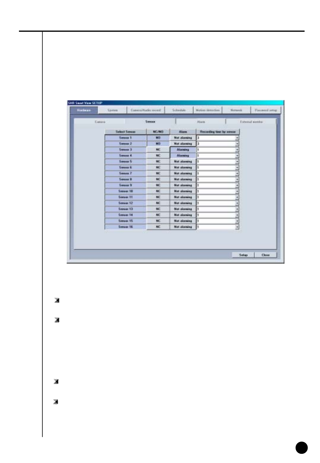
Description
Hardware [Sensor]
Select Sensor
: The number of external sensors and input terminal should be correspondent to each other.
▶ NC (Normal Close Type sensor)
: While on detection mode, choose this when sensor is near the point of contact
▶ NO (Normal Open Type sensor)
: While on detection mode, choose this when sensor’s contract point is open.
NC/NO
: Configure Sensor
Each time when the button is clicked it will change to [NC]<->[NO] and vice versa.
(Default is set to [NC])
Alarm
: While on Sensor detection mode, alarm will be on when sensor activates.
Recording time by sensor
: When there is a signal from sensor connected to system, this function is to setup time
which will record camera’s image linked with sensor.
(It can be setup from 1 second to 10 seconds).
20
20
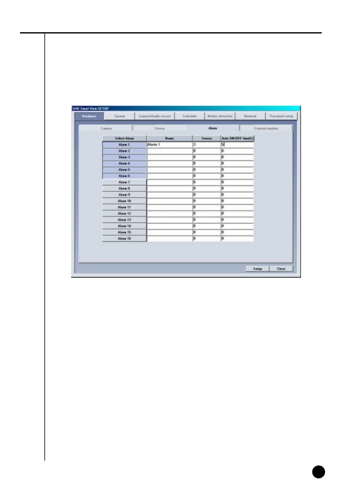
Function
Hardware [Alarm]
・ It indicates whether alarm will be used or not and setup sensor and time of output produced.
・ Output of alarm will be either ON/OFF when any sensor or moving object is captured.
It can control light, siren, speaker, and other external equipment.

21
21
Select Alarm
: This button is to choose output of alarm terminal you wish to setup.
Name
: Input name of alarm to use
Description
▶ When button is pressed: Appropriate alarm is selected
▶ When button is not pressed: Appropriate alarm is not selected
Sensor
: If you want alarm to automatically operate from external sensor, input external sensor that’s
linked to alarm.
For example) If you wish to operate number 1 sensor when number 3 activates,
choose alarm 1 and input “3” for following item.
Auto ON/OFF time(S)
: Input continuance of operating time for control output in second after sensor signaled.
(You can set it up to maximum of 255 seconds, default value is set to 0 second)
22
22
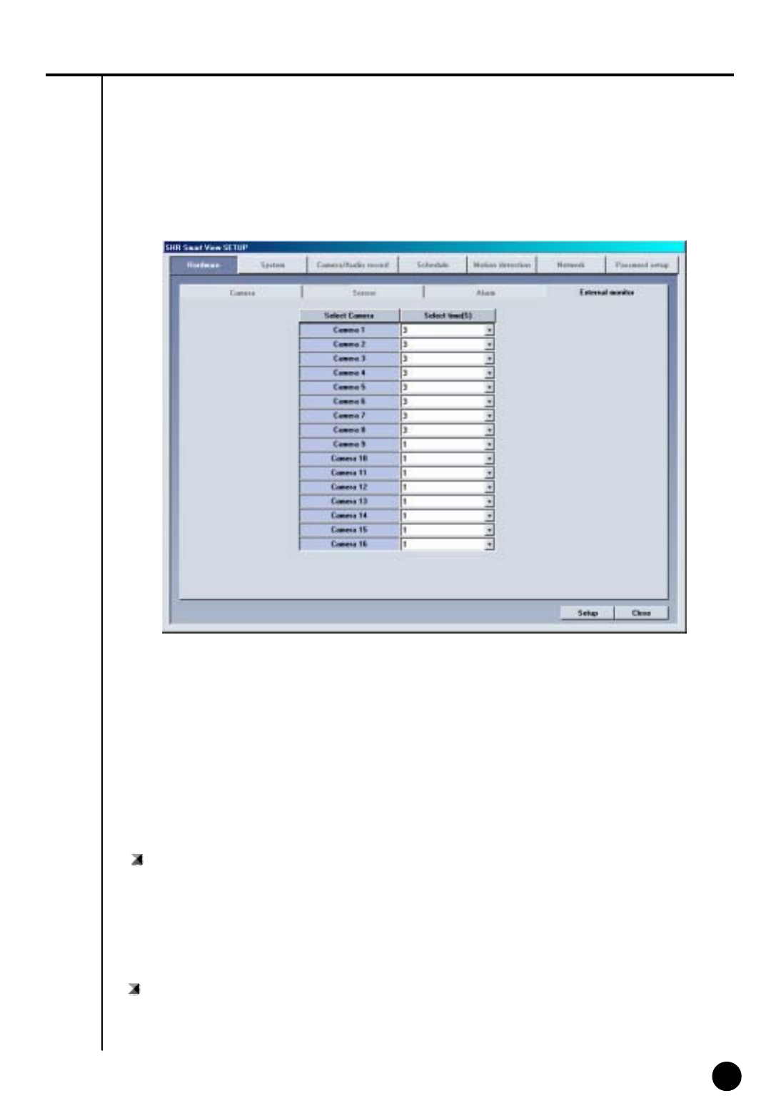
Description
Hardware [External monitor]
External monitor function produces output for image from DVR using analogue monitor (TV).
Select Camera
: Choose the camera which will produce output by external monitor
The output will be automatically produced according to setup time
Description
Select time(S)
: The output from external monitor should be assigned in second (From 1 sec to 10 sec)
▶ When button is pressed: Appropriate camera is selected
▶ When button is not pressed: Appropriate camera is not selected
23
23
2
System
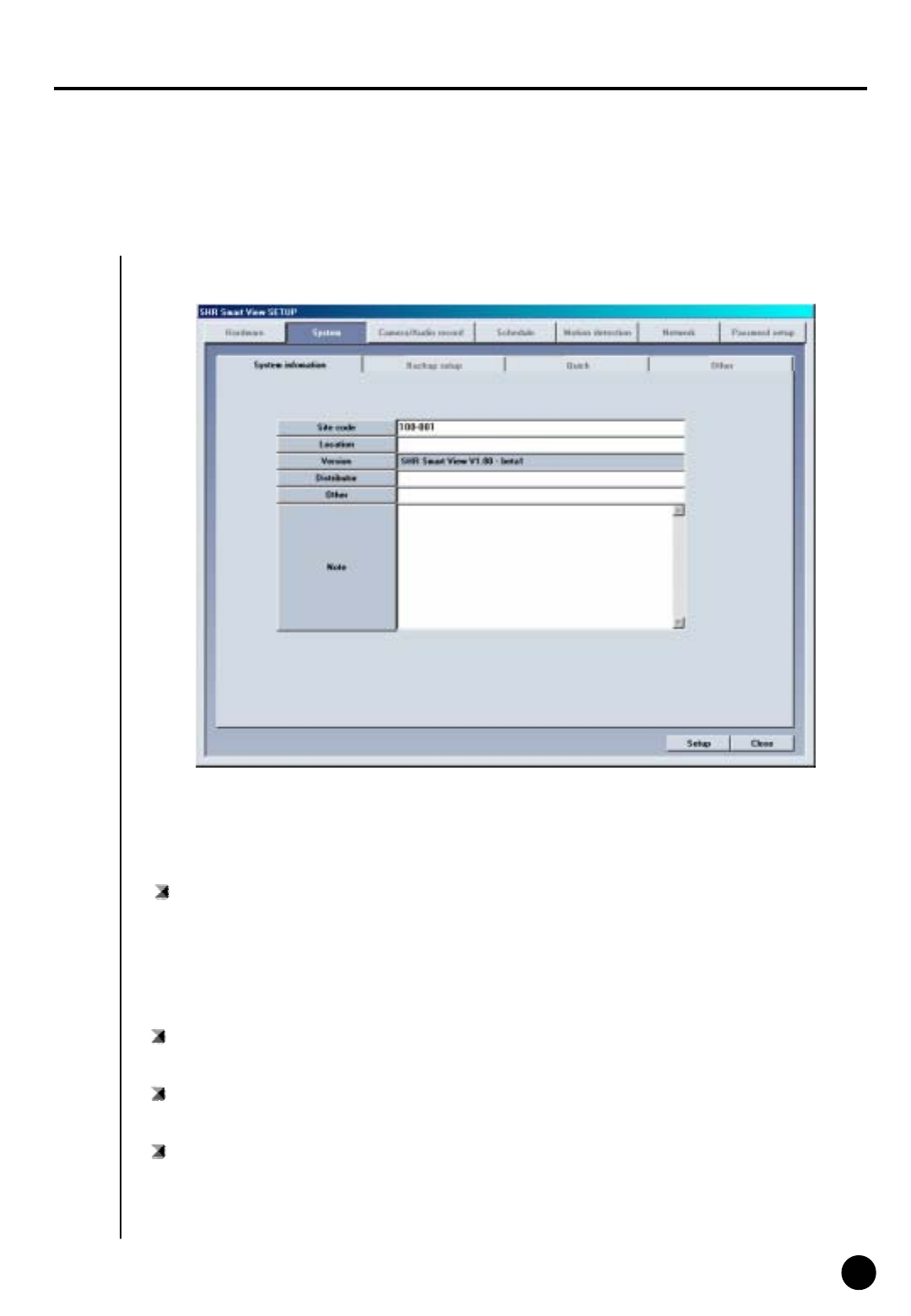
System [System information]
Site code
: Default is set to 100-001
The value may change at your discretion but anything must be inputted.
Description
☞ When connecting from Center to Site, it simultaneously searches and compares site Code
and password. If either site code or password is wrong, then the connection will not be made.
Location
: Input name of place where system is installed
Model
: Contains information of program
Distributor
: Input name of installer
24
24
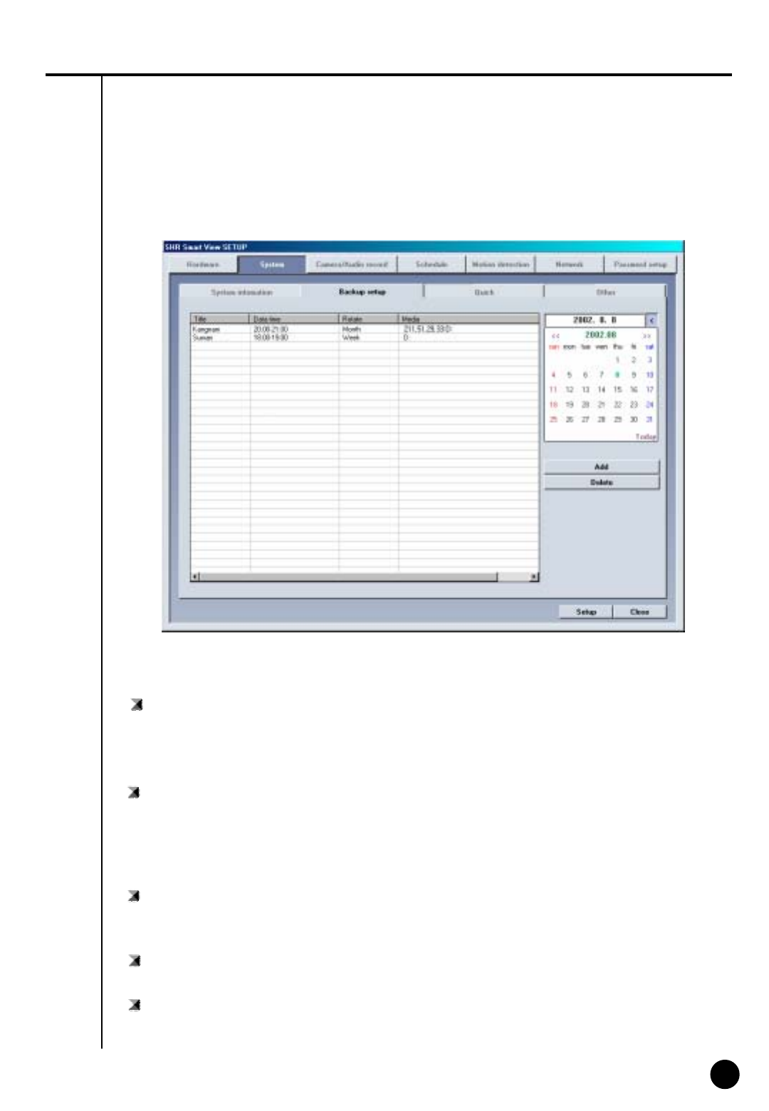
System [Backup setup]
Backup schedule setup
・ This backup media will show reserved list of backup data which will record data, assigned time
for backup, and etc.
・ According to assigned backup schedule, it will backup in order.
Description
Calendar
・ Calendar will appear in Pull-down type like picture above when you click on [>] button indicated
beside the current date.
You can check backup schedule list assigned by days and current date will be displayed if you
click “Today”.
Add: It adds assigned and rotation time of backup schedule data and data to be recorded in
backup media.
Delete: It deletes reserved category from backup schedule setup.
Setup: If [Setup] is not selected, reserved information will not be stored from backup schedule list.

25
25
Title
: Input name to be add on backup schedule list
Date/Time
: Selects start and end time for backup data
▶ It must be setup after current recording time.
▶ If it was setup before current recording time, then it will be ignored and won’t be added to
the list when [Add] button is clicked.
Method to add backup schedule
Backup start time interval after
: After backup data has finish its recording, it assigns when the backup will start after data
has finished its backup.
▶ Possible select time will be from 1 to 4 hours
Rotate option
: Repetitive rotation cycle can be maintained by assigning assigned date and
Year/Month/Week/None basis for backup data
▶ If [None] is selected, only one day setup can be made for assigned date/time.

26
26
Media list
: Choose backup data to record backup media
▶ It can be added up to 8 from media list and if fail to record on initially setup media,
it will automatically back up to next media.
▶ Selection should be made as following: HDD, CD-RW, removable drive, Network drive
except floppy disk, etc. It supports almost every language oriented logical/physical media.
You can select remote drive using IP address.
Up/Down/Delete
: Priority of backup media can be move from down/Up, and it can delete media that’s already
setup.
Setup
① Overwrite mode : This function will record data after deleting old data when there is not
enough space available to backup the data
② Priority : Assign priority of backup data
Add
: Add designated backup to backup schedule list
Add media
: Backup data can add media which will be recorded
▶ Backup media can be added maximum of 8
▶ Backup after precedent backup : Wait until the current work is done; start the backup
after current backup and waiting data have finished their backup.
▶ Backup after current backup : Start after current work is done; when current data’s
backup is completed, do not backup the waiting data if the other data was selected first.
27
27
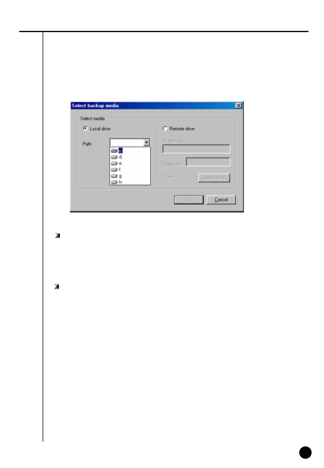
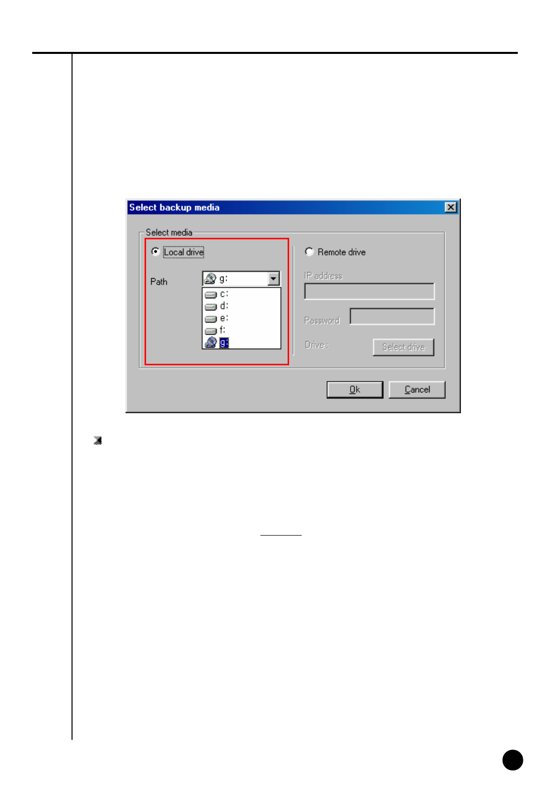
Local drive
▶ You can select HDD or removable drive (MOD, DVD-RAM, ZIP, USB HDD etc), CD-RW,
and Network drive.
▶ It supports every drive language oriented logical/physical media.
Remote drive
: Using IP address, this is used when backup from remove area where Center S/W is installed
▶ In order to backup from remote area using IP address, remote PC or File Server must have
Center S/W installed, and Remote Backup Server program (provided when Center S/W is
installed) should be executed (refer to Manual for Center Program)
▶ In order to do remote backup setup, IP address and password located by remote PC or file
server should be the same and remote backup server program should be executed
Method to select backup media
28
28
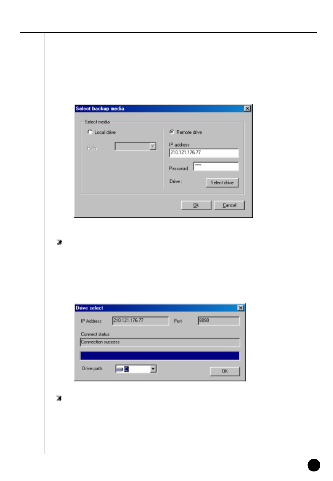
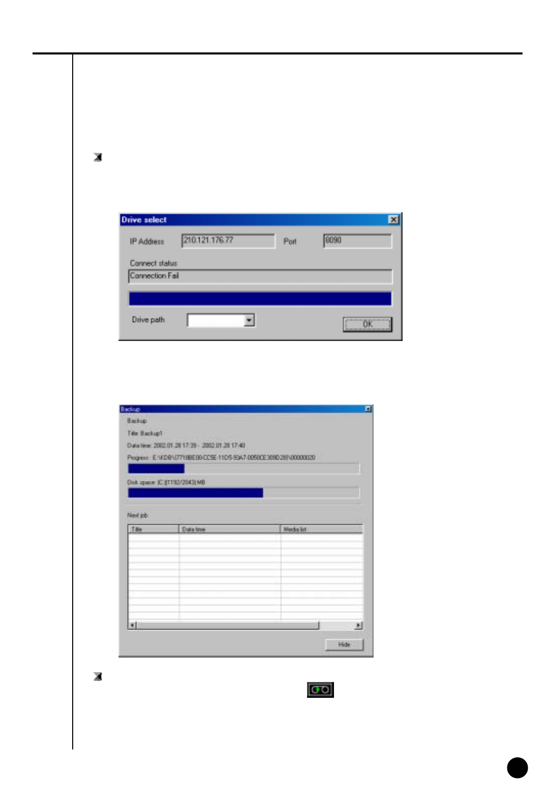
Select drive
: Input IP address and password and select [Select Drive].
▶ In order to connect to Remote backup server for remote backup, remote IP address and
registered password from Remote Backup server program is needed.
(If password is not registered,select [Select drive] button after IP address from remote site
is inputted.)
Drive path
: If connection is made successfully using selected IP address and password, you may choose
an appropriate backup media drive from remote PC or File server.
Remote drive
29
29
Connection Fail
: If selected IP address and password is different or Remote Backup Server program has not
been executed from remote PC or File Server, then connection will fail and you may not be
able to choose backup media drive.
Backup
: While backup is progressing, animated icon will appear on top of screen. When you
double click on it, you can check on current data’s backup progressing process and waiting
backup data list.
▶ Click [Hide]Button to close backup window
Indication of Backup status
30
30
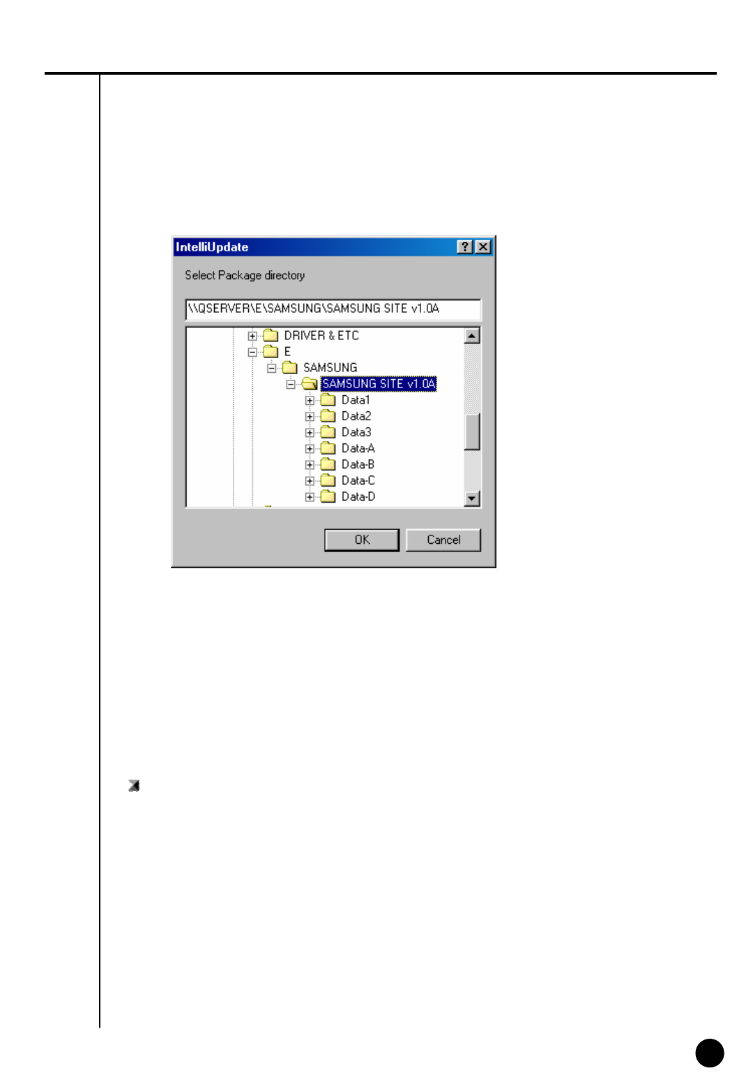
System [Quick]
Select Package directory
▶ Click [OK] after selecting hard disk or joint network folder which is store in a new version
▶ Appropriate folder must include package folder(Data1, Data2, Data3, Data-a, Data-b, etc.)
or all files from package folder must be included in one folder.
Description
Description
When [Quick] is selected, Intelli Upgrade window will be executed to let you choose new
package for program version. This function is to upgrade to a new version that’s stored in hard
disk or joint network folder.
☞When upgrading to a new version using Intelli Upgrade, upgrading does not support floppy
diskette. Therefore, we recommend you to upgrade after copying the whole media or on a hard
diskette.
☞If there is no file or package folder in certain folder due to a wrong folder designation, or if
the damage had occur to the file, then it will not be considered as a normal package so the
program will not upgrade normally.
31
31
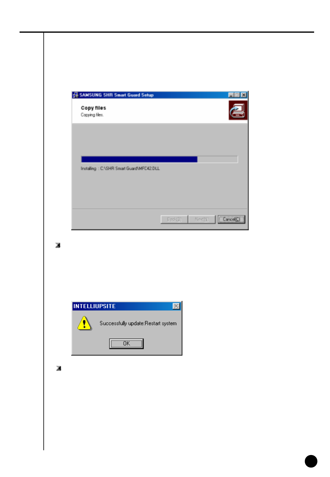
Check integral package file & program installation
▶ Installing process of a program window will appear when you designate package folder
▶ Installing process will show twice for testing integration package file and for program
installation. DigiNet program, which was executed during program installation, will end
System reboot
: System need to be restarted when upgrading a new program version is completed.
32
32
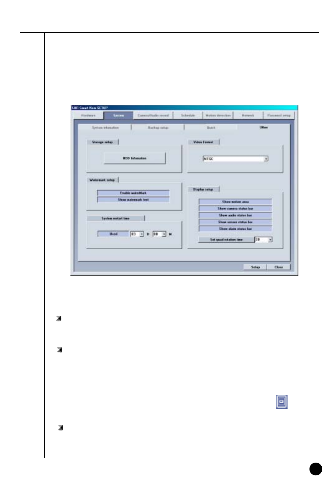
System [Other]
Description
Video Format
: Choose either NTSC or PAL
Display setup
: It sets up status bar appeared from surveillance screen or area
▶ When button is pressed: Appropriate status bar or area appears from detection mode
▶ When button is not pressed: Appropriate status bar or area don’t appear from detection
mode
☞ In order to find out the status of Audio, Sensor, Alarm의 Status bar, click
(audio/sensor/ alarm button) from lower part of the screen.
Set quad rotation time
: setup the rotation time in sec to display in 4ch display
33
33
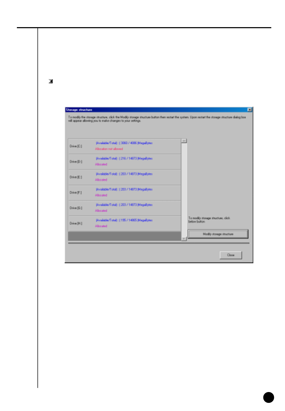
Storage setup
: This function modifies possible disk space of data and allocation status for each drive
▶ Window below appears when [HDD Information] is clicked
① Drive allocation
▶ Displays Allocation of HDD
▶ Currently available disk space for each drive and allocation status can be checked
②Modify storage structure
▶ You can modify the allocation on each drive
▶ You can re-allocate DB setup for each drive by clicking [Modify storage structure].

34
34
☞[Note] What is WaterMark ?
BMP and JPEG images can be modified anytime by user.
To ensure the original image which can be modified, special protection called
‘watermarking’ is enabled onto the image.
Any changes to an original image, including just one pixel, will inform you that the image
has been modified.
When recorded image was modified from DigiNet program, WaterMark authentication
and WaterMark check will tell you whether the image was modified or not.
Watermark setup
▶Using watermark
① This function inserts Watermark authentication mark on image to be recorded.
② When this function is selected, image will indicate WaterMark on the image.
▶ Displaying watermark text
① This function inserts Watermark authentication mark on image to be searched
② When this function is selected, image will indicate WaterMark onthe image.
System Restart time
: setup the automatic rebooting time for everyday.
(This is used to make system more stable.)
▶ Default setup is “Used”, in order to disable this click “Used” button again.
It will change to “No Use”
35
35
3
Camera/Audio record
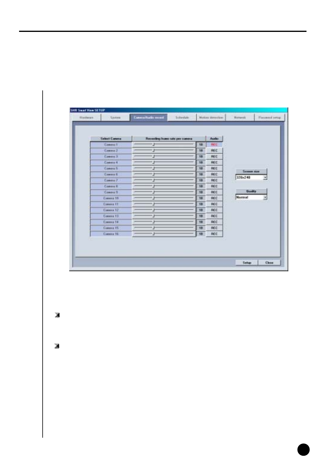
Camera/Audio record
Select Camera
: It indicates selected camera under Hardware[Camera] and camera that’s currently in recording
is selected above.
Description
Recording frame rate per camera
: Number of frames to be recorded are adjustable by each camera
▶ Put your cursor on scroll button and left click on it then choose the amount of time to record
(Recording time will be indicated in numbers on the right side)
▶ If you increase the recording time from the default setting, then availability of other cameras’
recording time will reduce.
▶ It could be more efficient to increase the recording time for places where it requires more
security.

36
36
Audio
: Decided to record audio for appropriate camera
① When REC button is pressed: It records voice for appropriate camera.
② When REC button is not pressed: It does not record the voice for appropriate camera.
▶ You can setup voice for specific camera and it records with voice signal that is being inputted
to microphone terminal.
▶ Voice is recorded according to recorded time for image and the sound data will be recorded
when the video signal start its recording. Therefore, sound data will not be recorded if the
video data was not recorded.
▶ In order to record voice, system must be installed with sound card or exclusive audio board.
(If Sound card or audio board is not installed, you can’t setup audio category and it will be
ignored).
▶ Only 1 channel can record voice when using sound card installed on main board. Voice
recording is supported up to 8 channel when using Samsung made exclusive audio board.
▶ If sound card and exclusive audio board are installed simultaneously, then we recommend you
to record voice using audio board.
[Tip]
・ When trying to backup already recorded data, it can backup with voice and it is possible to
record in specific drive. (But, if the voice data was recorded using audio board then backup
cannot be made and it will be supported from later version.
・ If sound card is embedded, 2way audio communication is possible to communicate with
S/W.
・ If 2way audio is connected using sound card, audio recording will discontinue.
・ Window must be setup separately for sound card when using 2way audio with sound card.
☞
Screen size
: Choose screen size
▶ Basically, resolution for 320*240 is best suitable for file size
(display and recording speed will improve twice when resolution is set to 160*120 but it will
decrease image quality. 640*480 resolution will give you excellent image quality but recording
speed will be decreased).
▶ Default value is 320*240 .
Quality
:To setup image quality
▶ Higher value gives higher image quality but file size for per frame will increase.
▶ Default value is set to ‘Normal’
☞Image size and compressed image is closely connected for the file size to be recorded.
37
37
4
Schedule
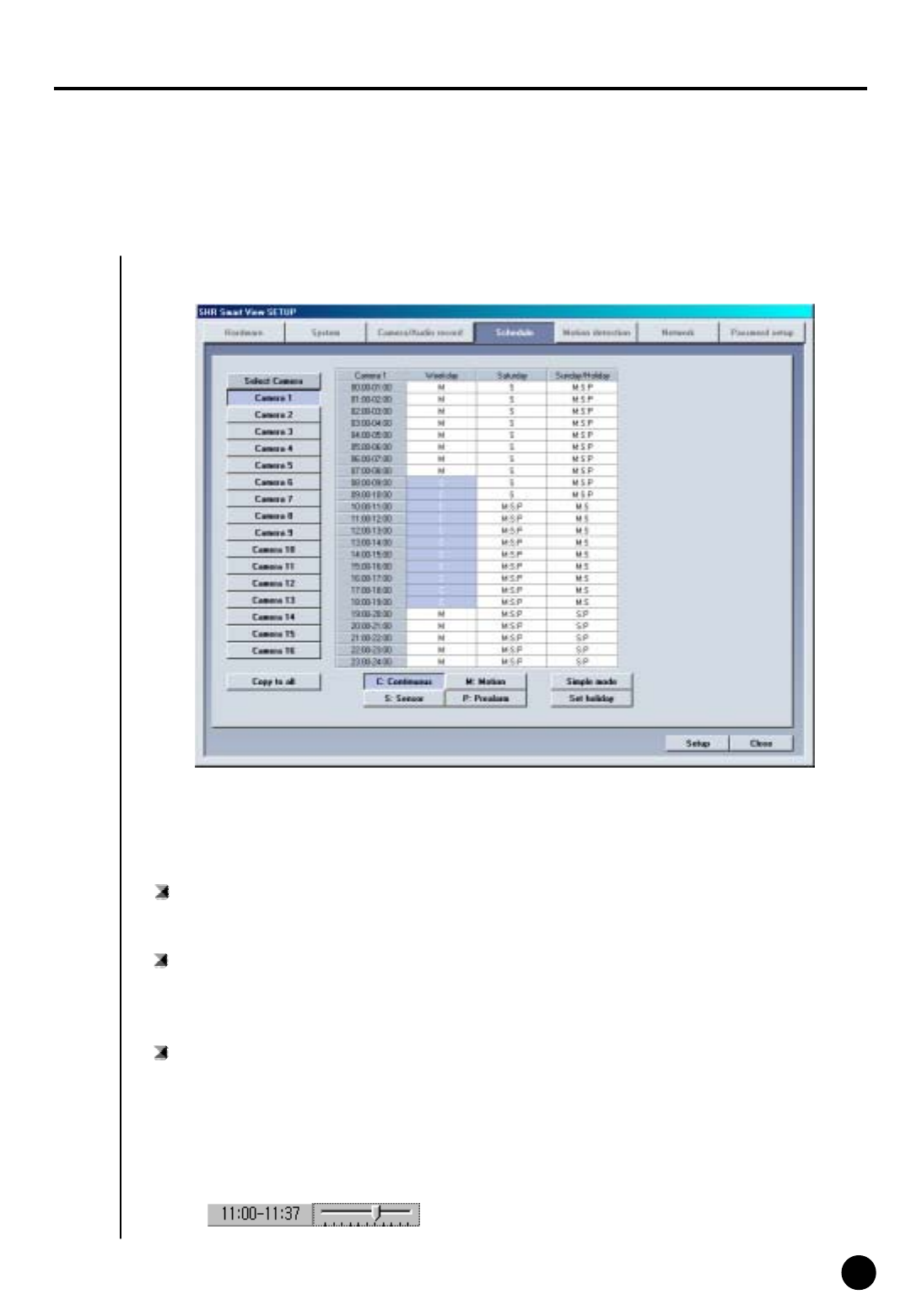
Schedule
Select Camera
: Choose camera number to use
Description
Setup Recording time
: This function is to set recording type for selected camera by each day and time.
▶ Select time of day and drag it to select area and then select recording mode form
[Record Mode] (C/M/S/P)
▶ If you need to set in minutes, double click on appropriate time then it will be set in minute.
Í01 ~ 59
minutes Î
Copy to All
: Information of currently selected camera will be copied and applied to every camera at once

38
38
Record mode (C/M/S/P)
: This function is to set recording type with day and time for selected camera.
▶ After choosing day and time from selected camera, selecting more than 1 record mode
will change selected time within selected time.
▶ If you erase all the record type from [Record Mode], selected setup time will change to
no record mode.
▶ Default is ‘Motion & sensor record’ of 24 hour continuous record.
[Tip]
① Continuous Record
- This is used when continuous recording is done without using motion detection.
② Motion detection record
- This is used when recording is done using motion detection.
③ Sensor Record
- This function is to record by inputted sensor signal.
- Sensor setup can be done by camera and use time. If sensor is captured within selected
time, related camera image will be recorded or related control will operate.
- Sensor input signal will be ignored if anything occurs outside the setup time.
- If related camera or time line is set to ‘Continuous Record’, then Sensor Record cannot
be used.
④Pre Alarm
- When a motion is captured on camera, then camera will record every moment of motion
occurrence in addition to five seconds before the motion was detected.
(But, recording speed may decrease if you setup several cameras with it).
- If the appropriate camera or time is set to ‘Continuous Record’ you cannot use Pre
Alarm function.
☞
•C : Continuous record
•M : Motion record
•S : sensor record
•P : free-alarm record
•no record
•continuous record
•motion record
•sensor record
•motion and sensor record
•motion & free alarm record
•sensor & free alarm record
•motion &sensor & free alarm record
Supported record typeIndication by record type
39
39
Simple mode
: This function lets you to select by minutes instead of hours depend on recording mode.
▶ When [Simple mode] is selected it will convert to [Advanced mode]and gives more option
to setup time. You can set different time for each time.
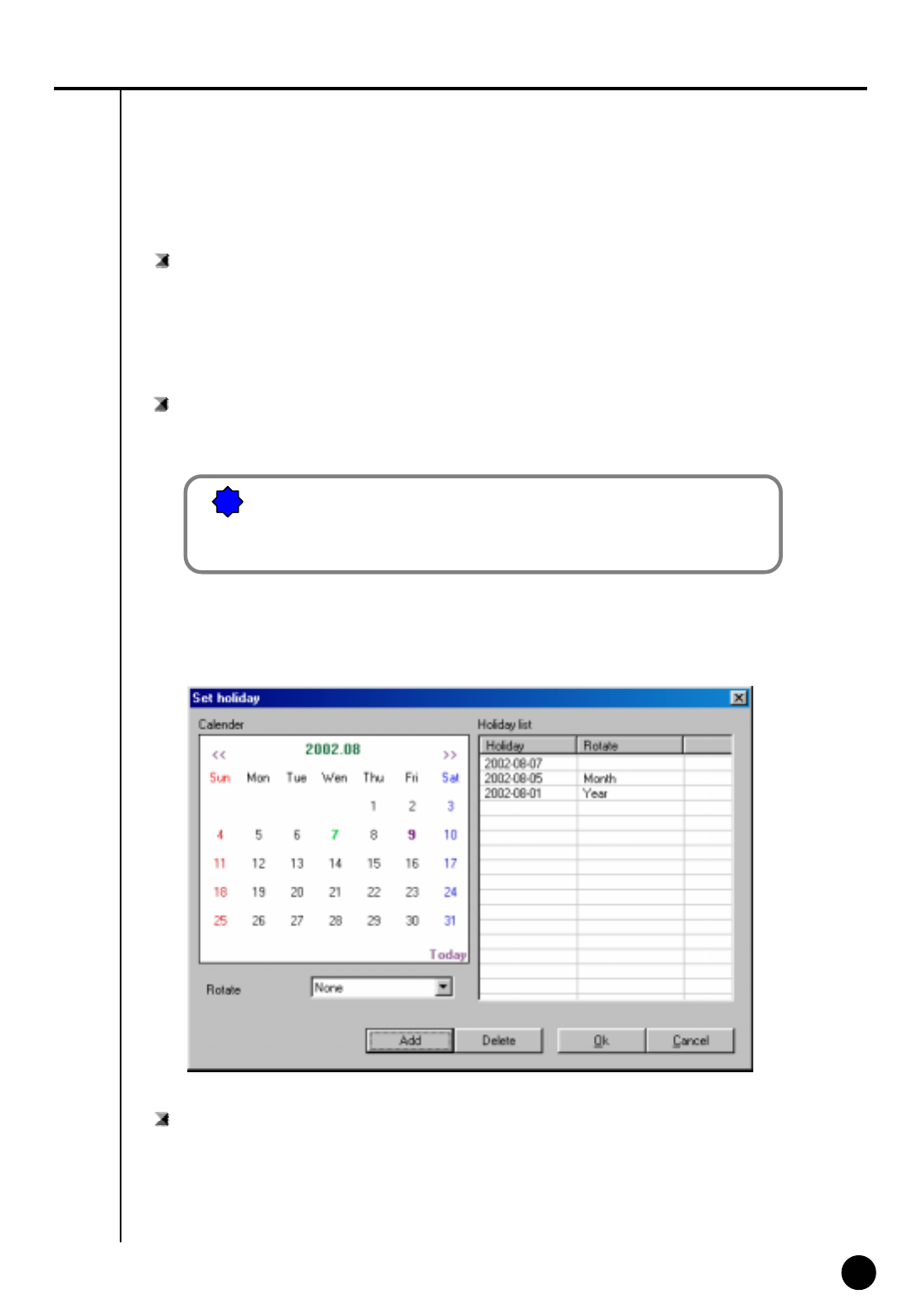
Set holiday
: You can pick any specific day of the year and set it as holiday
!
![Warning]
You must select [Save] button from [Schedule setup] in order to
store information on any changed holiday.
Setup Holiday
Calendar
: Select any day to designate as holiday
▶ << : Move to prior month
▶ >> : Move to next month
▶ Today : Shows current Month/Day/Year

40
40
Rotate
: You may choose specific Month/Day/Year as holiday
▶ If you select [None], one day will be assigned and for that specific day only.
Holiday list
: This function is to show designated holiday and its repeated date or period in a list
▶ Any additional holidays will be stored in the list in an alphabetical order.
Add
: This function is to add holiday you have designated.
▶ Designated holiday will be added to [Holiday list] when you click [add].
Delete
: This function is to delete stored holiday.
▶ In order to do this, select the date you wish to delete from [Holiday list] and click [delete].
41
41
5
Motion detection
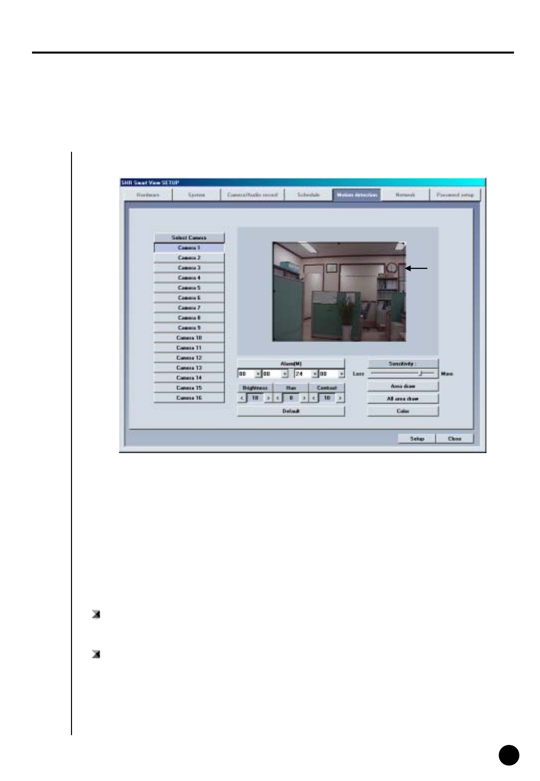
Motion detection screen
Select Camera
: Select the camera to setup
Feature
Screen Description
System starts recording when it detects any activity in the detection area without using sensors.
Sensitivity
: Adjust the motion detection sensitivity
▶Default value is “80”, which is the most proper
Detection
area

42
42
Motion Detection Area
▶Select the camera number and draw detection area using left click dragging.
▶Maximum five detection area can be made.
▶To remove the selected motion detection area drag mouse pointer toward out of box.
Area draw
▶ Entire area will be under motion detection mode when you click on [Area draw] button.
Default
▶Restore the default color configuration for the camera by clicking [Default] button
Alarm(M)
: System makes beeping sound to alert when there is any activity in the selected time.
▶When Alarm(M) button is pressed on : Alarm beeping works.
▶When Alarm(M) button is not pressed on : Alarm beeping does not work.
☞System beeps only when activity is detected in the selected time zone in recording schedule.
☞System does not beep if the camera is set to ‘continuous recording’
Brightness / Hue / Contrast
: Adjust Brightness, hue,and contrast
▶Default for camera is ‘18 / 8 /10’ , and the range is -127~126 and adjustable to each camera.
(Proper setup is required depending on site situation)
All area draw
▶ Entire area for every camera will be under motion detection mode when you click on
[All area draw] button.
Color
▶ If appropriate camera is black and white according to each camera number, then click to
convert it to Black and White camera (Default is set to Color).
43
43
6
Network
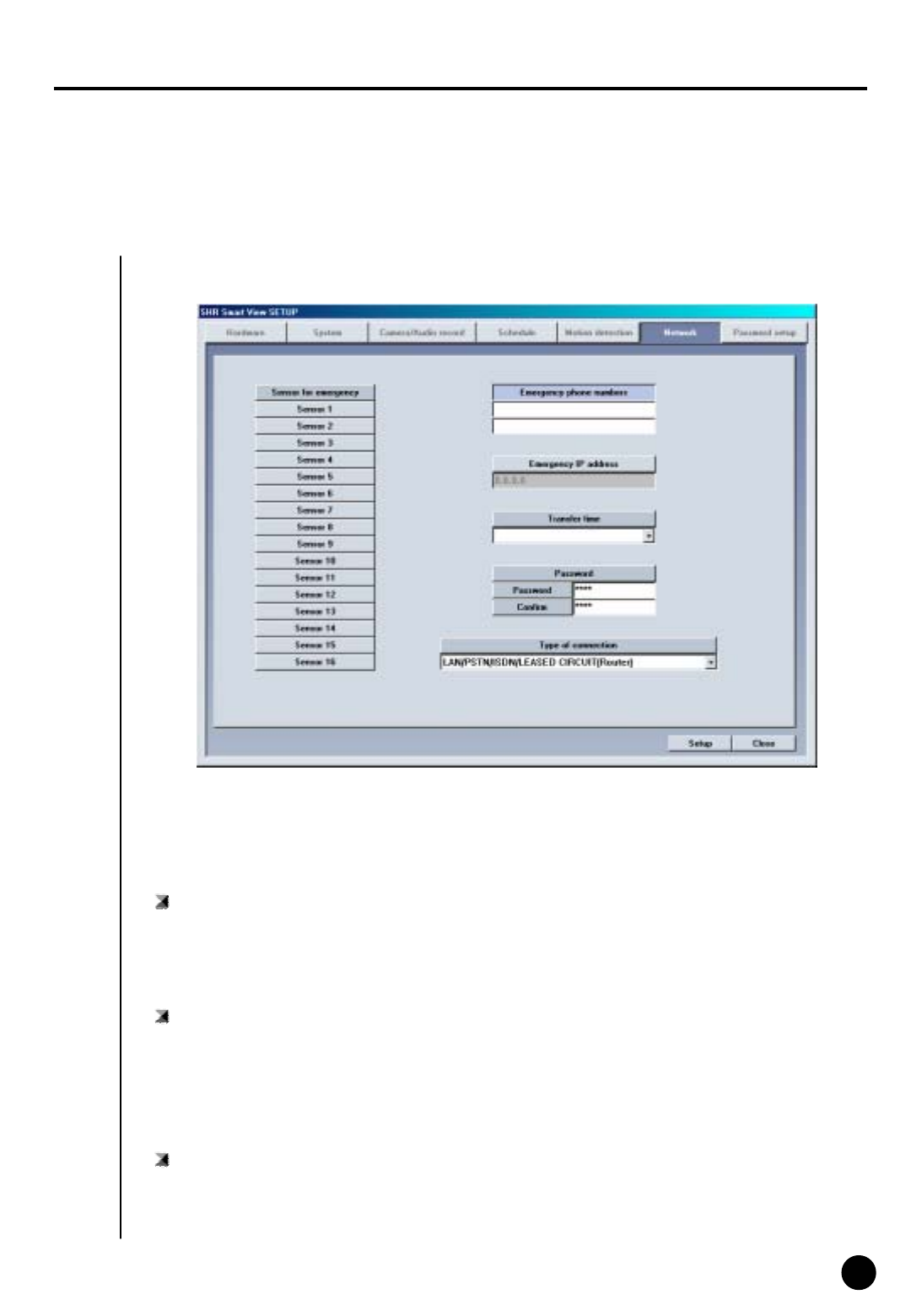
Network
Sensor for emergency
: If the sensor detects any signal it sends alarm to Center with the recorded image during the
designated time.
▶Click the sensor number to configure
Feature
Emergency phone numbers
: When the first trial fails to connect, it tries to connect to the second number which is emergency
phone number. This is to transmit emergency image or message.
▶Select [Emergency phone numbers] button and input emergency phone number. Up to two
emergency phone number can be used.
감지범위
Emergency IP address
: Transmit emergency image or message by connecting to the assigned IP address.
▶Click [Emergency IP address] button and input IP address.

44
44
Transfer time
: Select the duration in sec how long it will send images to Center on connection.
▶If any new signal is detected while connection, image transfer time starts again.
☞[Notice]
When you try to connect to site from Center, DigiNet checks the site code and password together.
Type of connection
▶For remote connection LAN, PSTN, ISDN, Leased Circuit can be used.
▶ISDN or Leased Circuit using router can be used. ISDN or PSTN can be used to connect to DVR
without router directly.
▶Check on “No Use” for no connection
Password
: Input required password to connect from Center p.c. (4 digit number is possible.)
[Password] : Input password required to access to DVR from Center.
[Confirm] : Input once again to confirm.
▶Default value is “1234”
45
45
PPP Setup for PSTN/ISDN connection without router
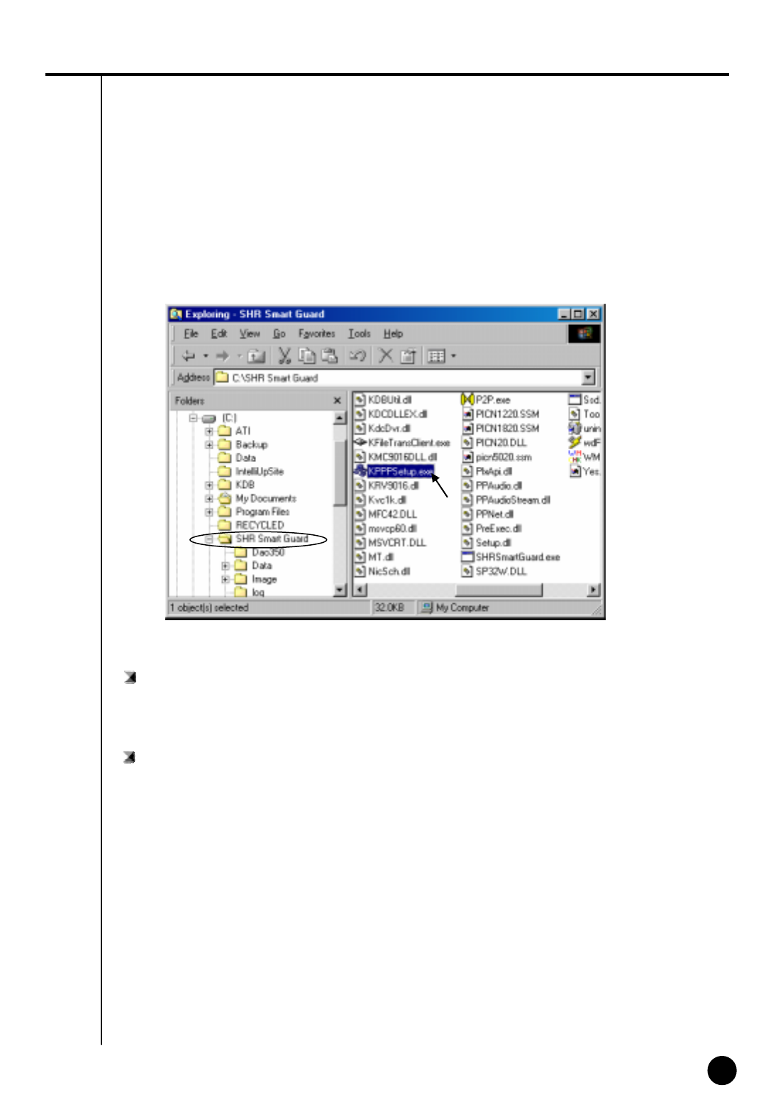
PPP Setup using KPPPSetup.exe
• To setup PSTN connection first install Modem in Windows. Then execute a file named
“KPPPSetup.exe” both in site and center and the required setup will be made automatically.
Required step before Installation
•In order to use KPPPSetup.exe program, CD-Rom drive may ask you to put in the original
Windows98 Second Edition or hard diskette must be copied with original file of Windows98
Second Edition.
•This program may not work properly when the system doesn’t have a modem installed.
• If a modem is not installed, first install modem and driver for that. Then execute KPPPSetup.exe

46
46
PSTN or ISDN setup on Windows98
①Install a modem for PSTN connection and ISDN Terminal Adapter for ISDN connection.
②Execute KPPPSetup.exe
③Reboot system after PPP setup is done.
※Please check the connection between Center and Site after rebooting the system.
☞[Notice]
• The system may request you original Windows98SE CD, then assign the path of Windows98SE.
• For ISDN connection without router, follow the same step as required on PSTN. In other words, just
execute KPPPSetup.exe
Items that will be installed by KPPPSetup.exe
• Dial-up Networking
• Dial-Up server
• Phone Dialer
• Dial-Up Adapter
• TCP/IP Protocol
• Modification in Dial-up Server properties
Notice
• Any windows of ‘Network Properties’ or ‘Dial-up Server properties’‘ should be closed before running
KPPPSetup.exe
• Do not execute KPPPSetup.exe twice at one time.
(Please wait until you see a message saying the system will reboot.)
• Select ‘LAN’ on ‘Communication Setup’ in Site software and select ‘PSTN/ISDN(No Router) in Center
software.
• KPPPSetup.exe should be installed on both Site and Center.
47
47
7
Password setup
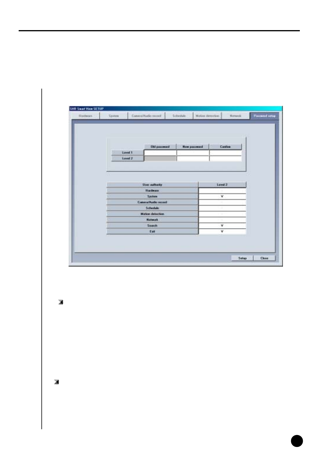
Password setup
Password Setup
: 1st level administrator can block some mode from 2nd level administrator.
▶ The function will be activated by ticking on that box.
Password change
: You can assign password to two operators and some functions can be set to work with
permission. (Operator 1 can be in charge of everything and operator 2 can modify permitted
items only.
Description
▶Old password : Enter current password you are using
▶New password : Enter new password
▶Confirm : Enter new password again

48
48
III. Search Screen
49
49
1
Execute Search Program
III. Search Screen
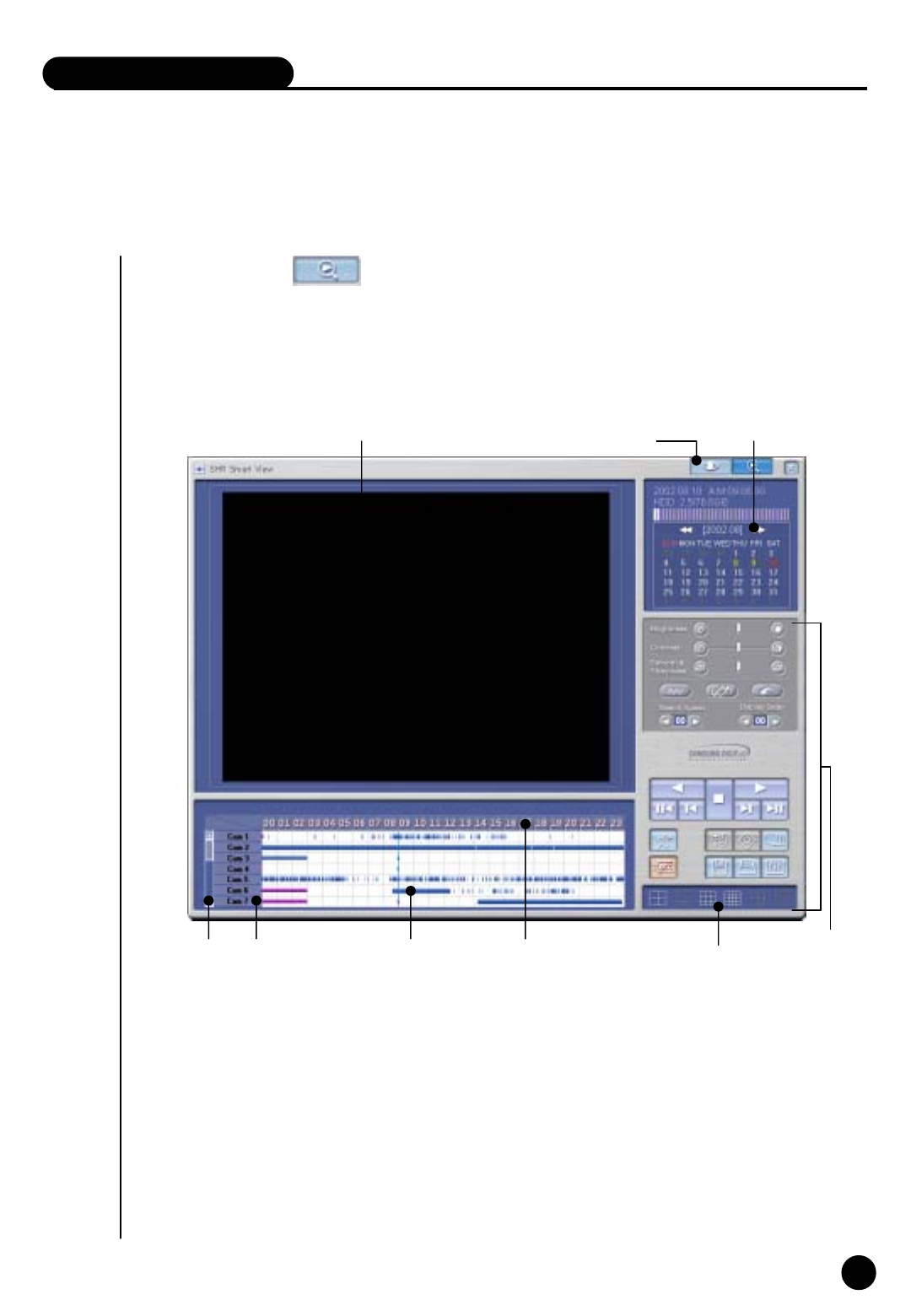
Search Screen
① Click on search button to execute from surveillance screen.
② Password screen will appear for securing purpose
Click [OK] if the password was not initially entered
Function
Convert to
surveillance mode Calendar
Search Window
Button
Scroll for Camera
Camera Record Storage Time indication and
Expansion for graph area
Organization of Search Screen
▶ Search screen Window
▶ Calendar which shows recording date
▶ Scroll to choose cameras to search, Camera Button
▶ Recording type and graph indication of storage
▶ Time indication and Expansion of graph area
▶Button for search screen
▶ Conversion to Search screen
▶ Screen Division
Screen division
50
50
2
Search Date and Time Selection
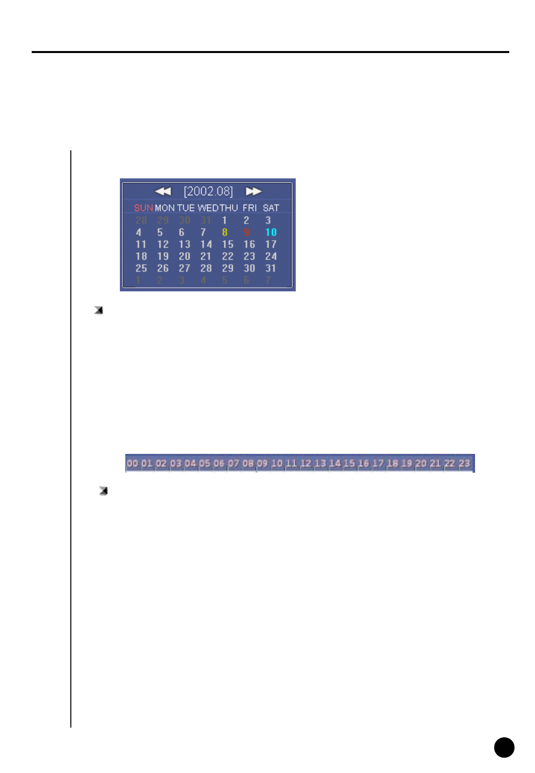
Calendar
Search ‘Date’
: Choose the Date you wish to search
▶ << : It shows whole calendar
>> : Calendar shows the following month
▶ On calendar, it will be indicated in yellow if anything is recorded on such date, red indication
means the one you clicked to search, and sky blue indicates that something is being recorded.
Time indication and expansion of Graph region
: It indicates time for the part where data is recorded.
▶ When you click on time, time zone will be expanded in three steps so graph region can been
seen more clearly.
▶ In case such country is applied with Summer Time, color will convert from Yellow
(default color) to pink but it will convert back to Yellow as soon as the Summer Time is over.
▶ Any modification of time caused by Summer Time will automatically change back to current
(actual) time.
Time indication and Expansion of graph region
☞ [Tip] What is Summer Time...
Sun rises early but sets late during summer so people tend to take advantage for this longest
period of daytime of the year by forwarding one hour which is known as Summer Time. Summer
time is widely used throughout the world and people forward one hour earlier than actual time at
the beginning and do the vice-versa at the end of Summer Time. For example, if the starting time
is 2 o’clock then you are to change the time to 3 o’clock and then change 3 o’clock back to 2 at
the end.
51
51
3
Select Camera
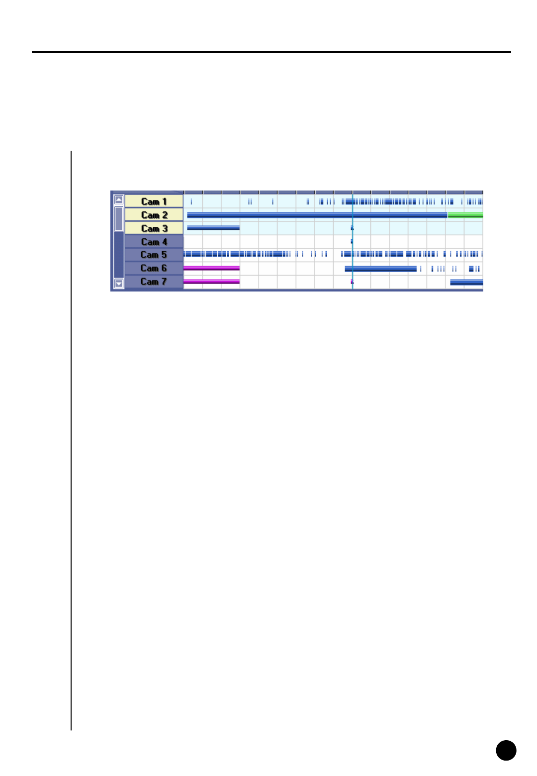
Select Camera
Camera Scroll button
: This function is to scroll search button from up and down.
Description
Camera
: Choose the camera number you wish to search
▶ When you double click on camera number, button and the colored graph of appropriate
camera number will be changed.
Indication of stored amount
: It indicates record type and storage amount by time.
▶ Violet graph – Recorded with continuous recording
Blue Graph – Recorded with motion recording
Red Graph – Recorded with Sensor recording
Green graph – Recorded with Pre Alarm, but there is no indication if nothing was recorded.
Search Bar
: This function indicates current time line of data which is being searched.
▶ You can immediately search for any recorded data by horizontally moving search bar.
☞[Note]
Black screen will be displayed if there is no image for the camera you selected.
❶
❷❸❹
❶
❷
❸
❹
52
52
4
Playing Recording
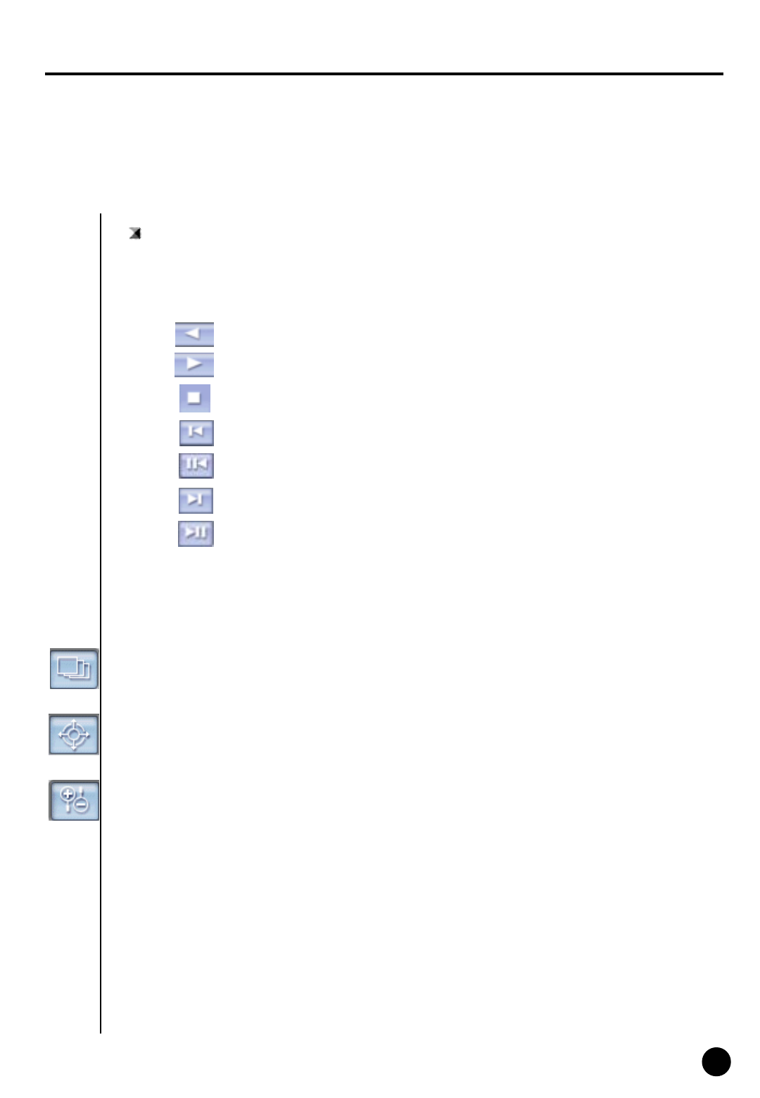
Playback
: Select the date, time and camera number to playback.
▶ Adjust search speed and delay to display as you want.
Search Tools
Panorama
:Display selected camera’s image consecutively in 4ch divided screen.
Backward Play
Forward Play
Stop
Play one picture backward
Go to the last one hour of the retrieved image
Play one picture forward
Go to the last one hour of the retrieved image
Zoom
: Zoom in and out. Gives five times magnification.
Digital Zoom
: Each click on Digital Zoom button converts among zoom-in / zoom-out / drag.
▶ Zoom-in (+) : Right click on certain spot zoom in up to 13 grades.
▶ Zoom-out(-) : Right click on certain spot zoom out.
▶ Drag : Move the magnified image by dragging
☞In the search mode zoom in or out is enabled only when one camera is selected.
(Zooming is not possible while playing multiple cameras’ image. Therefore, click ‘stop’ and
play One camera to zoom.)
53
53
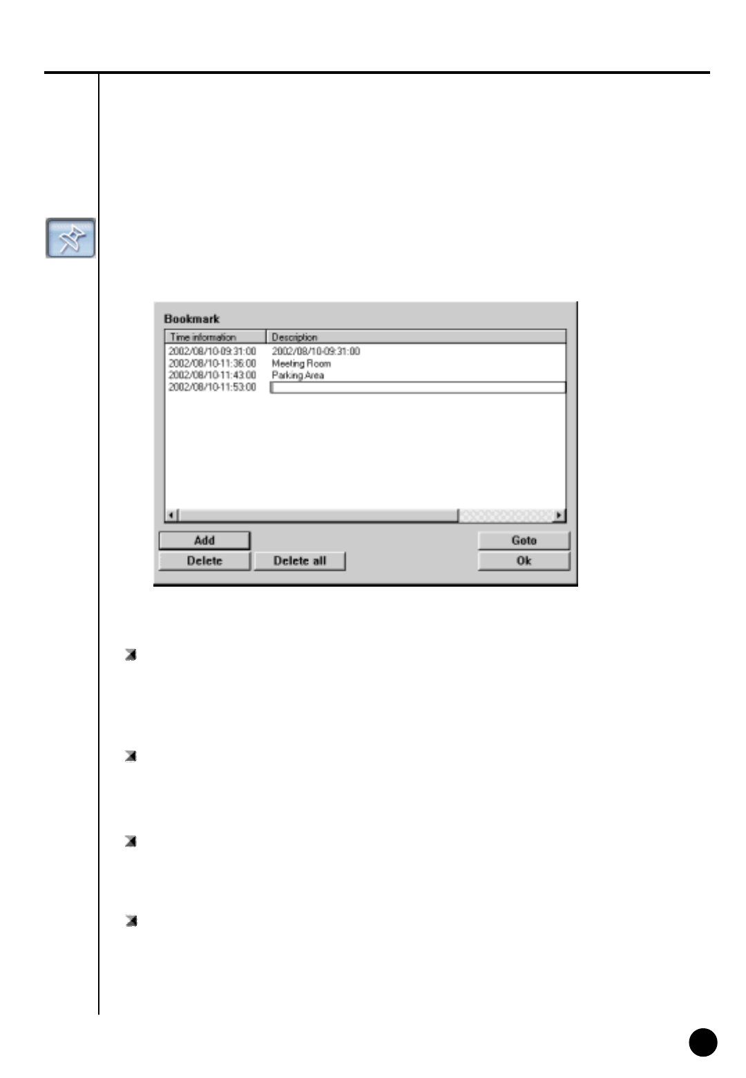
Bookmark
: Records the location of image under playback
You can go back to the recorded location directly next time.
Time Information
: Display time of bookmarked image.
▶When you add the image location during search the date and time will be saved in the order by
date and time.
Description
: You can input description on the bookmarked image.
▶If you do not input description the one in [time Information] will be input.
Add
: This is to add the image location to the bookmark list.
▶[Add] If you click [Add] button, the current image location will be added to the bookmark.
Delete
: This is to delete the bookmarked location.
▶In order to delete bookmarked record select it in the bookmark and click [Delete]

54
54
Delete all
: Delete all the bookmarked image location.
▶ All the image location will be deleted if you click [Delete all] button.
Goto
: You can go to bookmarked image location by clicking this button.
▶ Click [goto] button to go to the bookmarked location after selecting the bookmark.
OK
: Select [OK] button after adjusting bookmark information.
Recording during playback
: Image search speed will increase if DVR does not record while searching.
▶ In order to set it as recording during playback, click this button again.
(This will be disabled in monitoring mode.)
☞
☞[Notice]
Though the image recording goes on while searching, however, recording graph does not
change. You should go to live mode and come back to searching mode to see updated graph.
Search Speed
: Playback skipping the certain number of image.
▶ The number is not the number of actual image, but the one set inside Site program.
Display Delay
: Time to display one image on screen.
▶ 0 (Fastest) ~ 50 (Slowest)
Screen Division
: Playback recorded image in division.
▶ 4ch,9ch,16ch can be selected and deactivated mode cannot be used..
(8ch DVR supports only 4 and 9 division mode.)
55
55
5
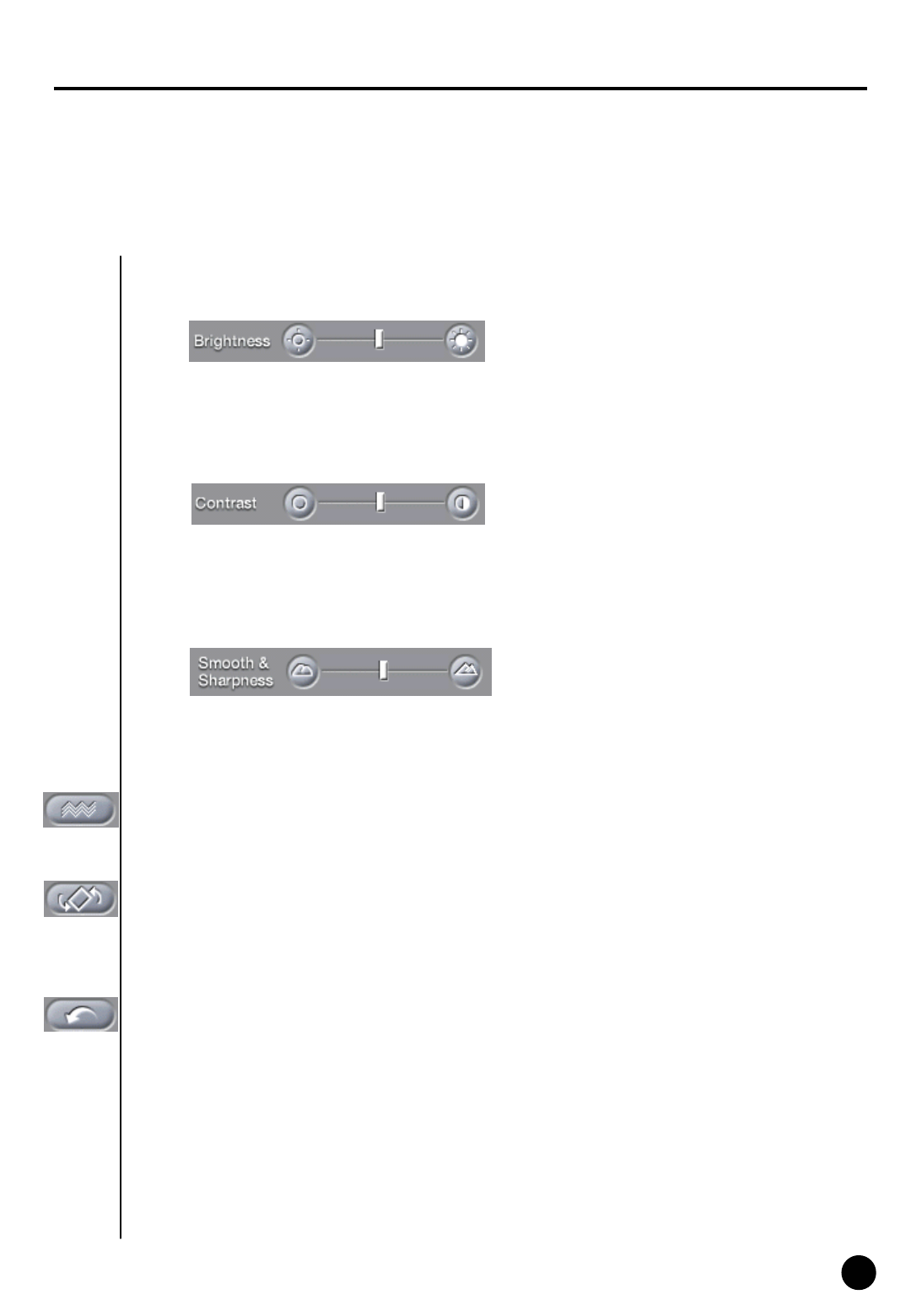
Search Tool
Brightness
: Adjust brightness of the image.
Contrast
: Adjust contrast of the image.
Smooth & Sharpness
: Make the rough image smooth and vague image clear.
Noise Reduction
: Reduce noise in the image.
Turning image
: Turn the image in the angle of 90, 180 or 270. And flipping is possible.
Restoration
: Getting back to the original image before modification by search tools.
☞ [Notice]
Search tools an be used for one camera’s image only. Therefore, you should click stop button
and choose one image to use above tools.
56
56
6
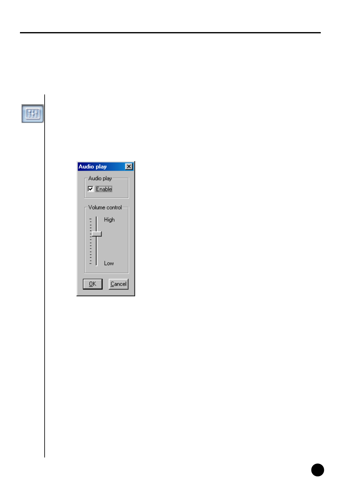
Audio Setup
Audio playback setup
: Playback with recorded audio.
▶Click on left button creates “Audio Play” window as below.
▶ Tick on the box next to “Enable” in “Audio Play” window.
▶ Adjust volume properly.
[Notice]
・Audio can be played only on one selected channel. You cannot play audio watching more than 2
channels. You should choose one channel to play audio.
・Video loss can take place within the first 1~3 seconds of play back, this is due to the video and audio
synchronization and is not a fault
・Audio can only be played back in normal forward play. Reverse Play or Frame Play is not possible
・Skip and delay cannot be used with audio play back.
・ Please refer to 『Appendix』for audio setup.
☞
57
57
7
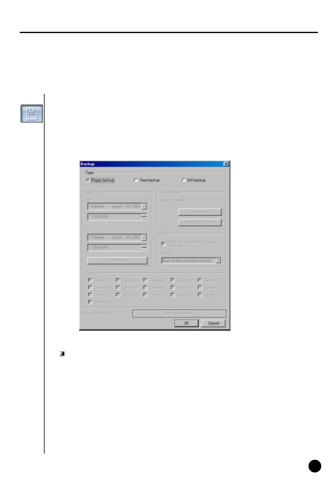
Data Backup
Backup
: copy restored data onto floppy disk or other media on a selected time or AVI format.
Floppy Backup
Floppy Backup
: This is used to backup one still image onto floppy disk in BMP or JPEG format. This image
can be viewed with other image viewer.
▶ When you click ‘backup’ icon while searching above ‘backup’ window will appear.
▶ Floppy backup gets activated during searching only one image.
58
58
Floppy Backup
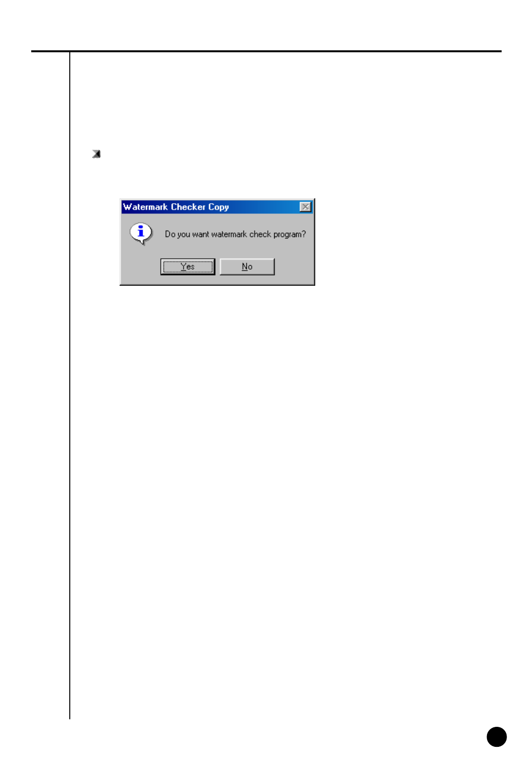
①Click [Floppy Backup] in “Backup” window and click [OK]
②Below ‘watermark checking’ window appears.
☞[Notice]
The image will be copied onto Floppy diskette in BMP or JPG format. The image will be copied
with the ‘watermark checker program’ to check to see whether the image was illegally modified or not.
③If you click ‘Yes’, the selected image will be copied onto floppy disk with Watermark checking
program.
▶Only one image can be copied in floppy disk backup and ‘watermark’ checking program will
be copied only at the first copying.
59
59
Watermark Check Program
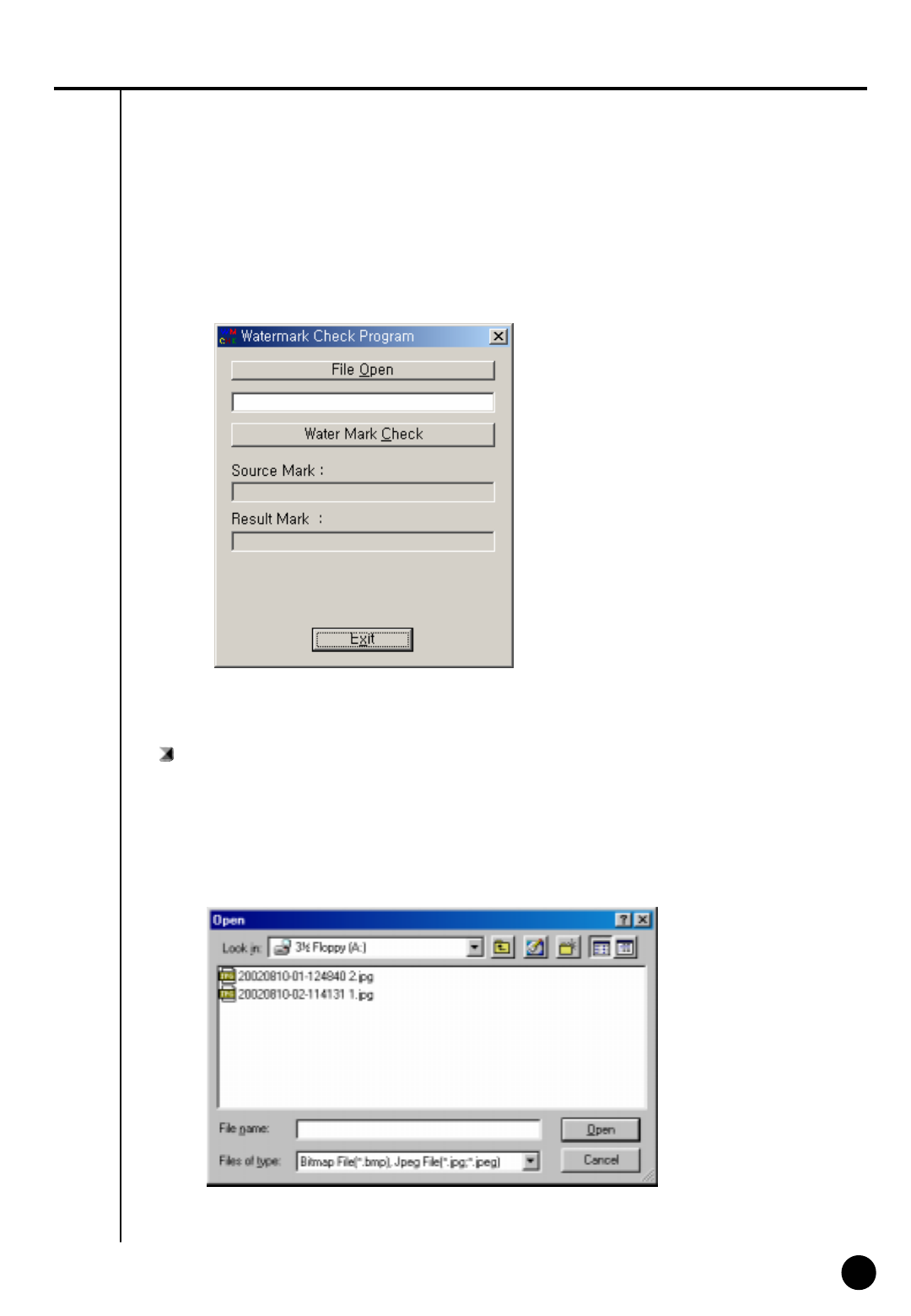
▶If you execute ‘WMChecker.exe’ which is copied to the Floppy Disk with the backup image,
following ‘WaterMark’ checking program appears.
▶If you click ‘File Open’ button, below widow will appear to check an authentication of the image
[ How to use Watermark Checker ]
: You can check the authentication of the image restored in BMP or JPG.
60
60
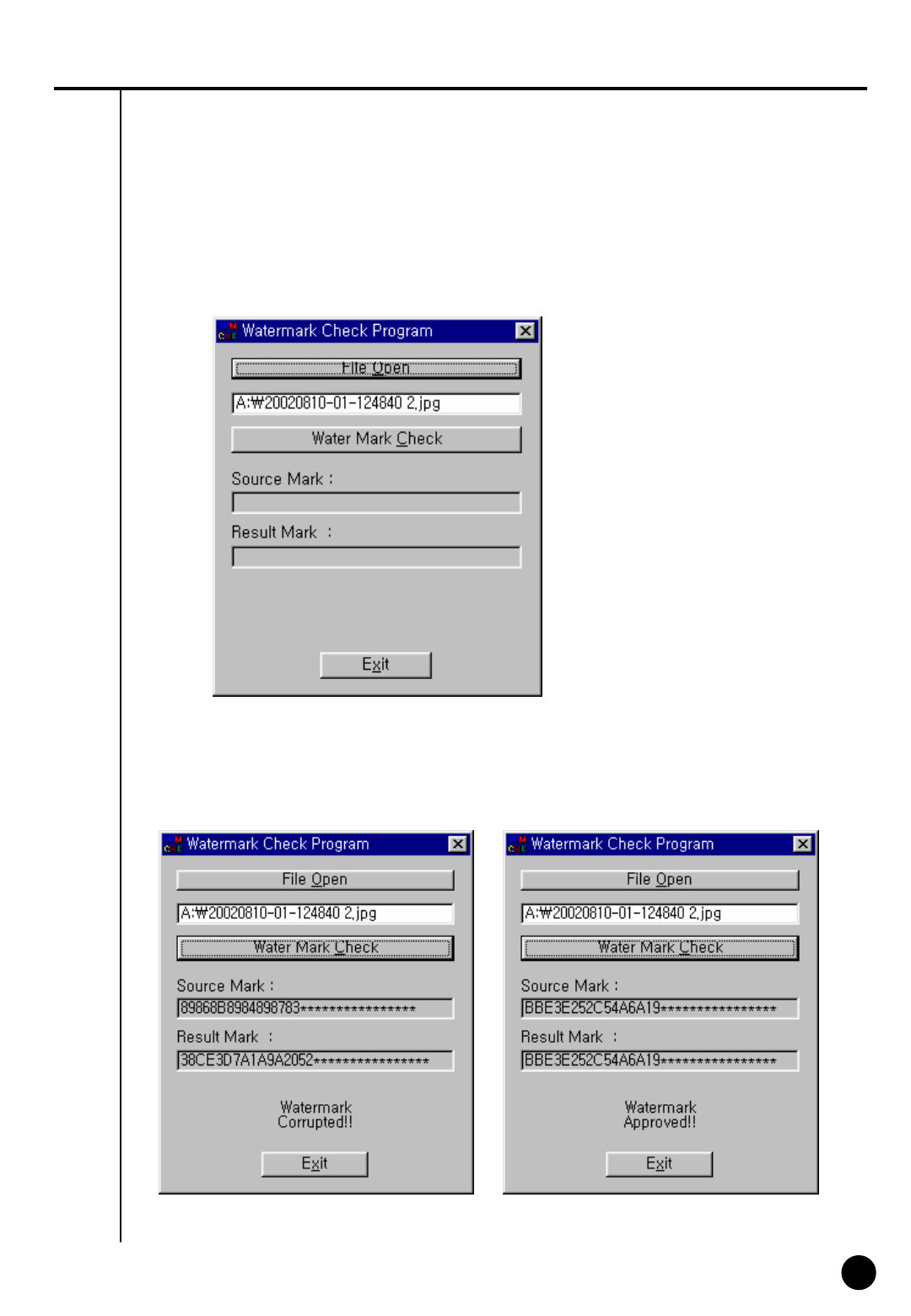
▶Once verification is completed windows similar to those below will appear.
< Corrupted image > < Uncorrupted image >
▶When you open the file name, a window below will appear. Select ‘watermark check’ to verify
the image.
61
61
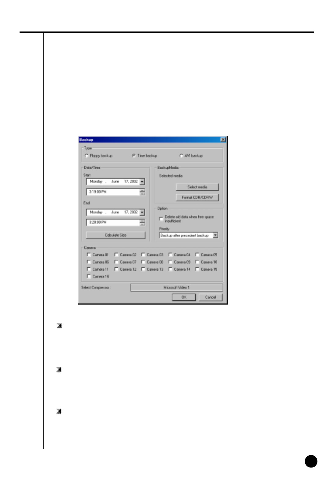
Time backup (Large Media)
: This is a backup using other than floppy such as HDD, CD-RW, mobile driver, network driver or
copy using IP address.
Backup by time
▶ This streaming data is our own data type. So this image cannot be read using other program
than SAMSUNG Center program.
Date/Time
: Select the time to start and finish backup.
▶ This time setup should be earlier than current time. If this is later than current time backup
does not work despite clicking [OK]
Calculate Size
: Click this button to calculate expected data size for the selected time.

62
62
Select media
: Media to use on backup.
▶You may select HDD, CD-RW, Portable drive, Network Drive, Remote IP Address except floppy disk
Option
[Delete old data when there is not enough space]
: This function will record data after deleting the old data when there is not enough storage space
to backup the data.
[Priority]
: Select the priority of backup data.
▶Wait until the processing work is done; start the backup after current backup and waiting data
have finished their backup.
▶Start after the precedent backup; when current data’s backup is completed, do not back up the
waiting data if the other data was selected first.
OK
: Backup will start from the designated backup media drive when you click [OK].
Format CDR/CDRW
: This is used when you select CD to backup data..
▶If CD was not formatted, use Direct CD program for CD formatting process. When you select
[Format CDR/CDRW], you can format CDR/CDRW media by Direct CD (Refer to appendix)
☞[Notice]
Direct CD program has to be installed in window in order to format CD.
63
63
CD-R/RW backup
• Select [Select media] from “backup media” window.
• From “Select backup media” window, select [OK] button after selecting CD-RW drive which you
will backup.
• You need to format CD in order to backup CD-R/CD-RW from DigiNet program.
• When the CD is unformatted or failed to Backup, please follow this step to Format the CD.
(Refer to page 72)
• In order to backup on CD-R/CD-RW, Direct CD S/W should be installed on the system.
• If the CD is formatted, follow the same way with backup to HDD, or removable drives
(DVD-RAM, ZIP, MOD, RB)
[ Backup onto CD-R / CD-RW ]
64
64
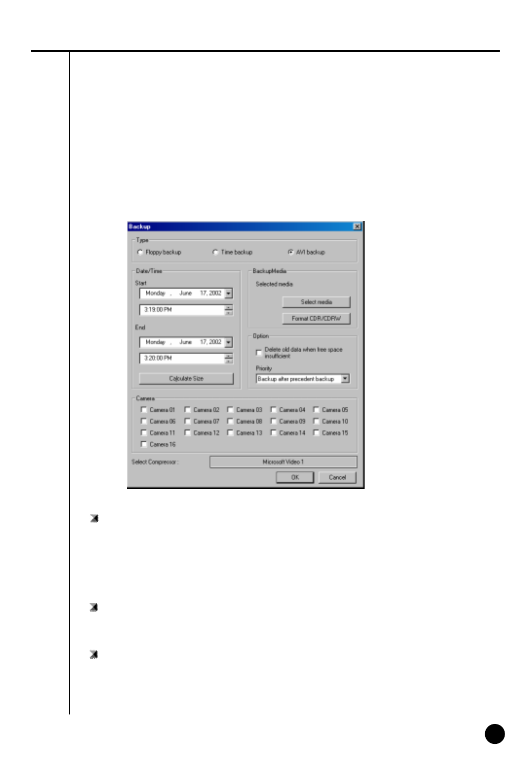
AVI backup
: converts compressed streaming data into AVI format so that windows media player can placyback
the backup data.
AVI backup
▶Data backup is available to HDD, CD-RW, mobile drive, network drive and remote drive using
IP address except for floppy drive
▶Backup by camera is available during backup in AVI format, and backup of Max. 5 min video per
one time is possible.
Date/Time
▶In case of backup into AVI, the time between start and end of backup is automatically set to Max.
5mins.
Camera
: select the camera number to backup in AVI.
▶ Multiple cameras can be selected and recorded in AVI.

65
65
Select Compressor
: You can select available compression codec under AVI backup.
Format CDR/CDRW
: This is used when backup media is CD.
▶When CD is not formatted a user should proceed CD format using Direct CD program, and once
he chooses [Format CDR/CDRW], Direct CD program begins to format CDR/CDRW media.
(refer to appendix)
☞[Notice]
In order to format CD, DVR should have Direct-CD installed.
Select media
: Select media type
▶HDD, CD-RW, Mobile Driver, or Network driver except floppy disk can be used.
• In order to format CD, DVR should have Direct-CD installed.
• When other advanced compression codecs then the basic Mpeg compression codec provided on
Window were installed, AVI files are saved into smaller sizes, the compression quality is advanced
and the time for backup is reduced.
• According to types of compression codecs, number of selected cameras and set backup time, AVI
backup time may differ significantly.(When the basic codec provided on Window is used, codecs of
Mpeg4 Video Codec v2 over are recommended.)
• In case of backup into AVI files, audio data are not backed up but only video data are backed up into
AVI files.
• According to the resolution of saved video data, resolutions of AVI files into which the data are backed
up are as follows.
SAMSUNG Resolution AVI File( NTSC / PAL )
640x480(768x576) 320x240
320x240(384x288)
160x120(192x144) 160x120
☞[Tip]
66
66
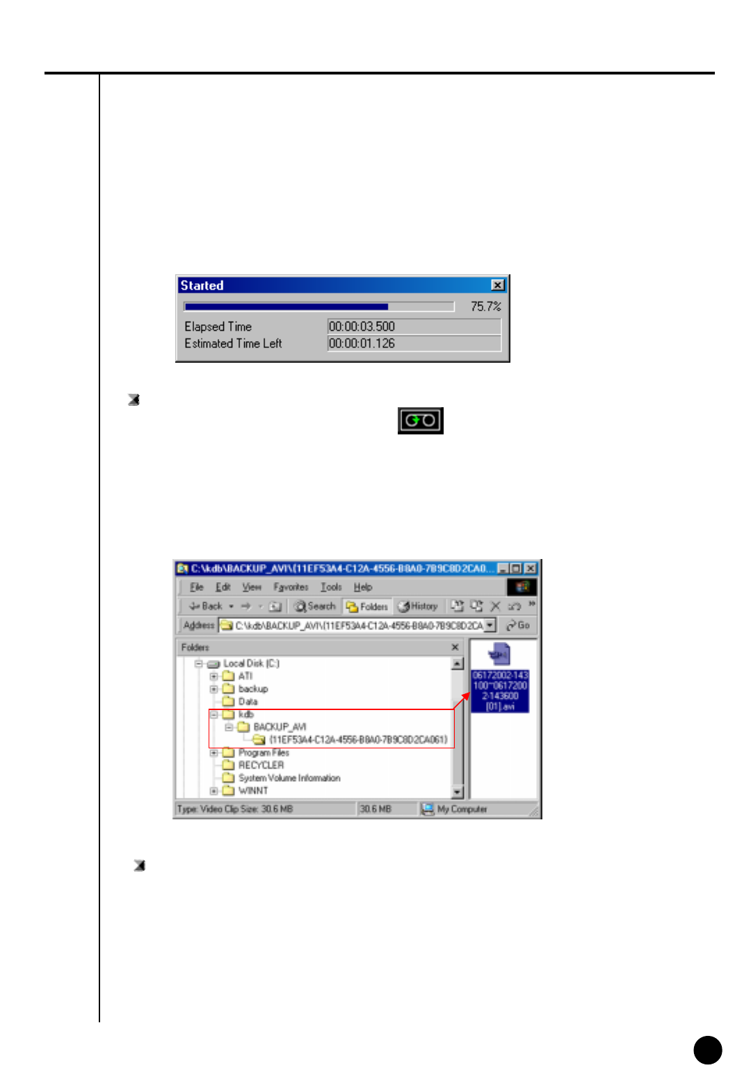
[AVI Backup Status]
Started
: When you double click on animated icon located on top of image while real time is
in progress, current backup data and backup status and its progress rate, lapsed time, and
remained time can be checked.
[AVI Real Time Backup File]
Choose AVI Real Time backup file
: In order to check AVI Real time backup file, double click on recorded file from assigned drive
“KDB\BACKUP_AVI\ {xxxxxxxx-xxxx-xxxx-xxxx-xxxxxxxxxxxx}\month day year-time min
second ~month day year-time min second[camera No].avi” then you can check appropriate
file information using
Window Media Player which is separately provided by real time player or window.
67
67
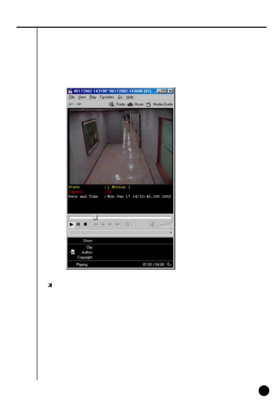
AVI Real Time Backup File and Caption information
: Using media player provided from Window, caption information of Date and time, days,
camera number and etc can be indicated. Other real time player shows image only.
☞[Note]
We recommend minimum of v6.4 for Media Player and if caption information cannot be
checked, then choose ‘Caption’ from [View] to check such information.
68
68
8
Print Search Screen
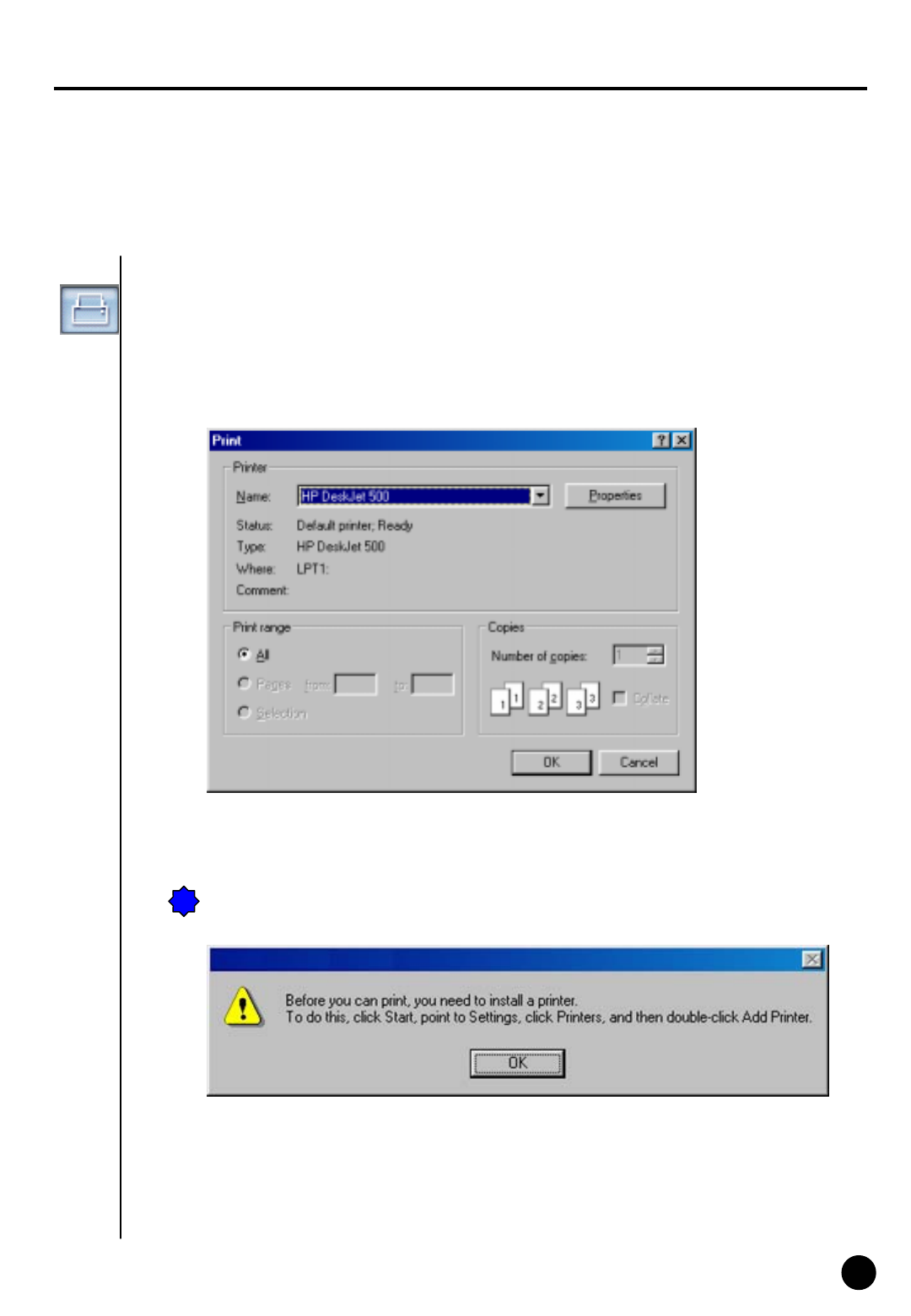
Print
: You can only print when Print button is selected from searched screen while one image is
magnified, then click on [OK] button shown below (Size and Brightness must be adjusted in
advance).
!
!Following ERROR will occur if print setup is not completed

69
69
☞[Tip]
Print Setup
1. Click Start ÆSetup ÆPrint from Windows 98
2. Double click on ‘Add Printer’ when Print Menu appears
3. Click [Next] when Add Pinter Wizard executes
4. Check to see if [Local Printer] is selected and then Click [Next] if Printer is connected to system.
5. Select Print Driver from the box where it asks manufacturer, name, and model of printer.
6. Print setup is completed when Driver is installed on screen.
Size of Image Output
1. It produces output and the printed size is equivalent to the magnified ones seen from the screen.
When printer is not working,
1. Check to see whether printer is setup from Window or not
2. If the printer is setup to the system but still not working, then check to see if cable or power code
are connected.

70
70
IV. Appendix
71
71
1
Manual ISDN Setup without router
IV. 부록
[When there are a few dial-up servers depending on the ISDN modem]
• Basically ISDN setup will be done automatically when you run KPPPSetup.exe. However, there might
be cases that you need to setup manually when there are a few dial-up servers depending on the IDSN
modem. In that case, please follow the next step.
• When the ISDN modem supports a few dial-up servers, you should select a proper dial-up server that
supports ISDN among the dial-up servers.
• Above step should be done after executing KPPPSetup.exe.
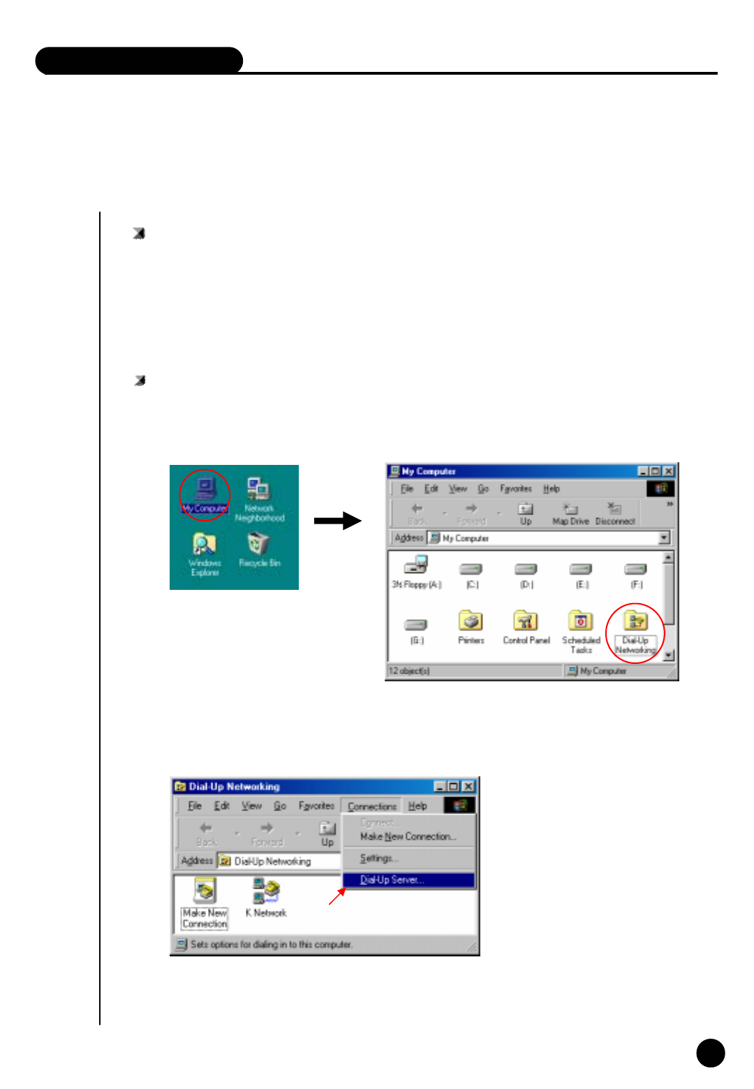
Manual Setup
①Select ‘Dial-up networking’ on ‘My Computer’ in background
②‘Connections’ Æ‘Dial-Up server’.
72
72
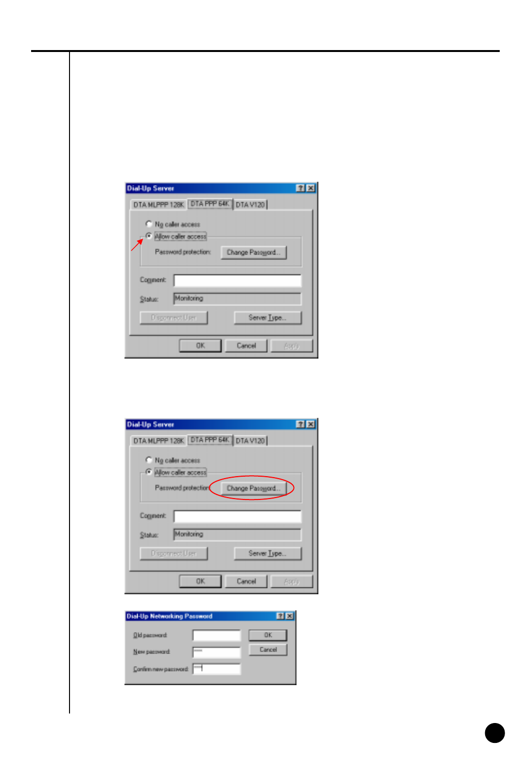
③Choose “Allow caller access”
.
④Enter to change password and input ‘1234’ for all three blanks.
73
73
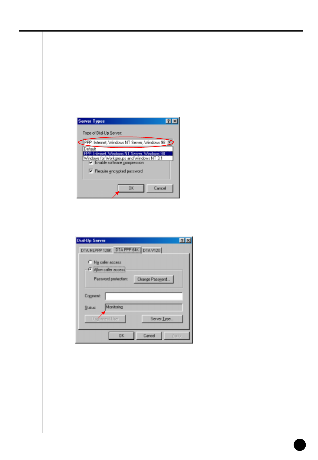
⑤Choose “PPP: Internet, Windows NT server, Windows 98”on ‘Server Type’.
Check “Enable Software Compression”and “Require Encrypted Password”and click “Apply”
button and “OK”.
⑥Make sure if there is “Monitoring” in the “Status”.(The type of dial-up server is different
depending on the ISDN modem as you see above.)
74
74
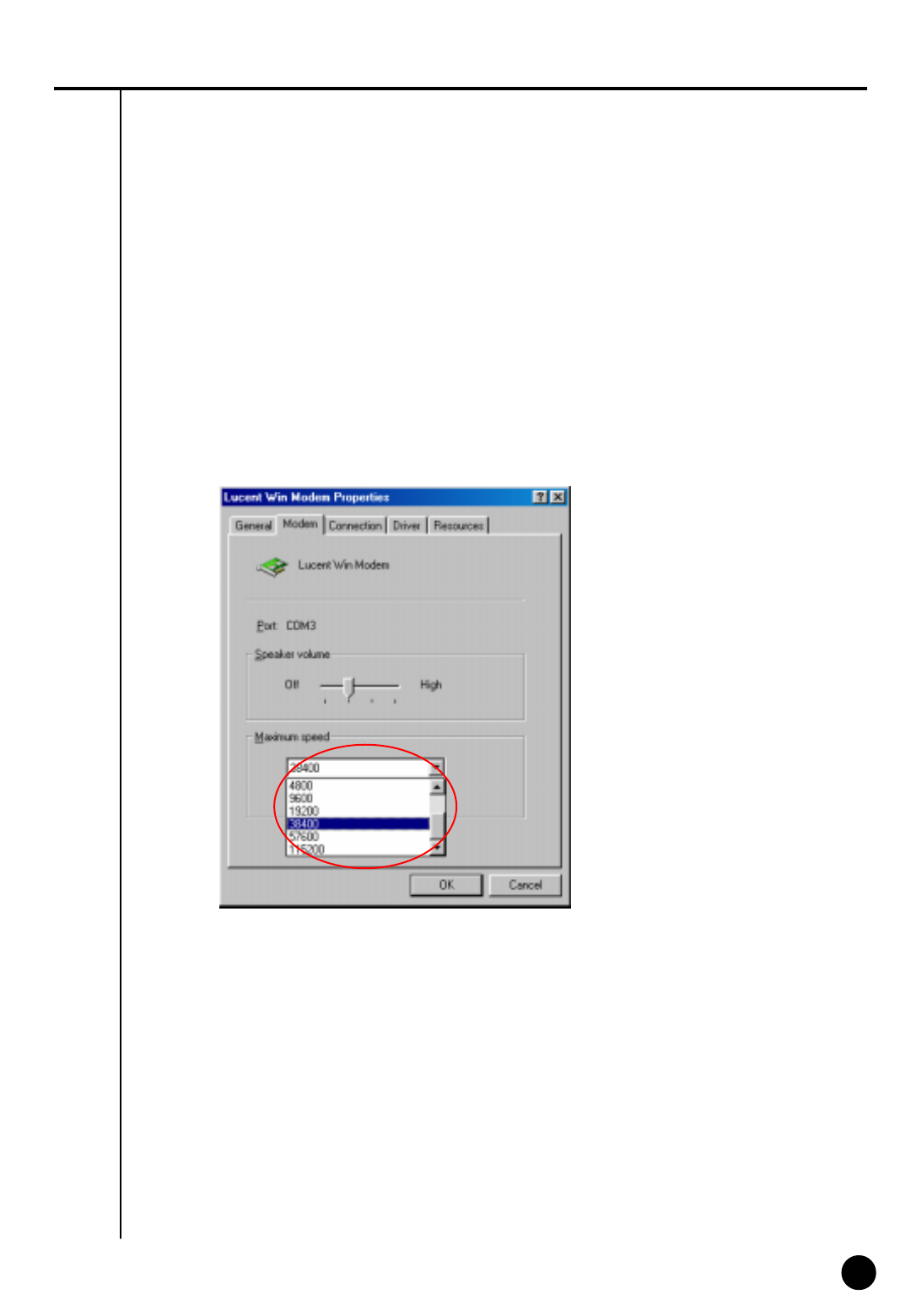
[Notice] connection speed
When you get disconnected a lot on PSTN or have a bad connection, go to ‘Control Panel” Æ
“Modem” Æ“General” Æ‘Properties’.
Select ‘38400’ on Maximum speed on “Modem properties” (Select ‘115200’ for ISDN.)
To make the connection between Center and Site set ‘Maximum speed’ the same.
(Connection might be bad depending on their line status like noise and defective line.)
☞
☞
75
75
2
Formatting a CD using Direct CD
IV. Appendix
[Formatting CD using Direct CD]
When you try to backup on an unformatted CD or in case where the message of backup failure
has shown, format the CD as follows.
※ Below contents is based on Direct CD v5.1. If some other message comes up, please
refer to Direct CD manual.
CD format and backup
① Select [Media Select] button in “Backup Media” -> Select CD-R/RW drive in “Local Drive”
-> Click [OK]
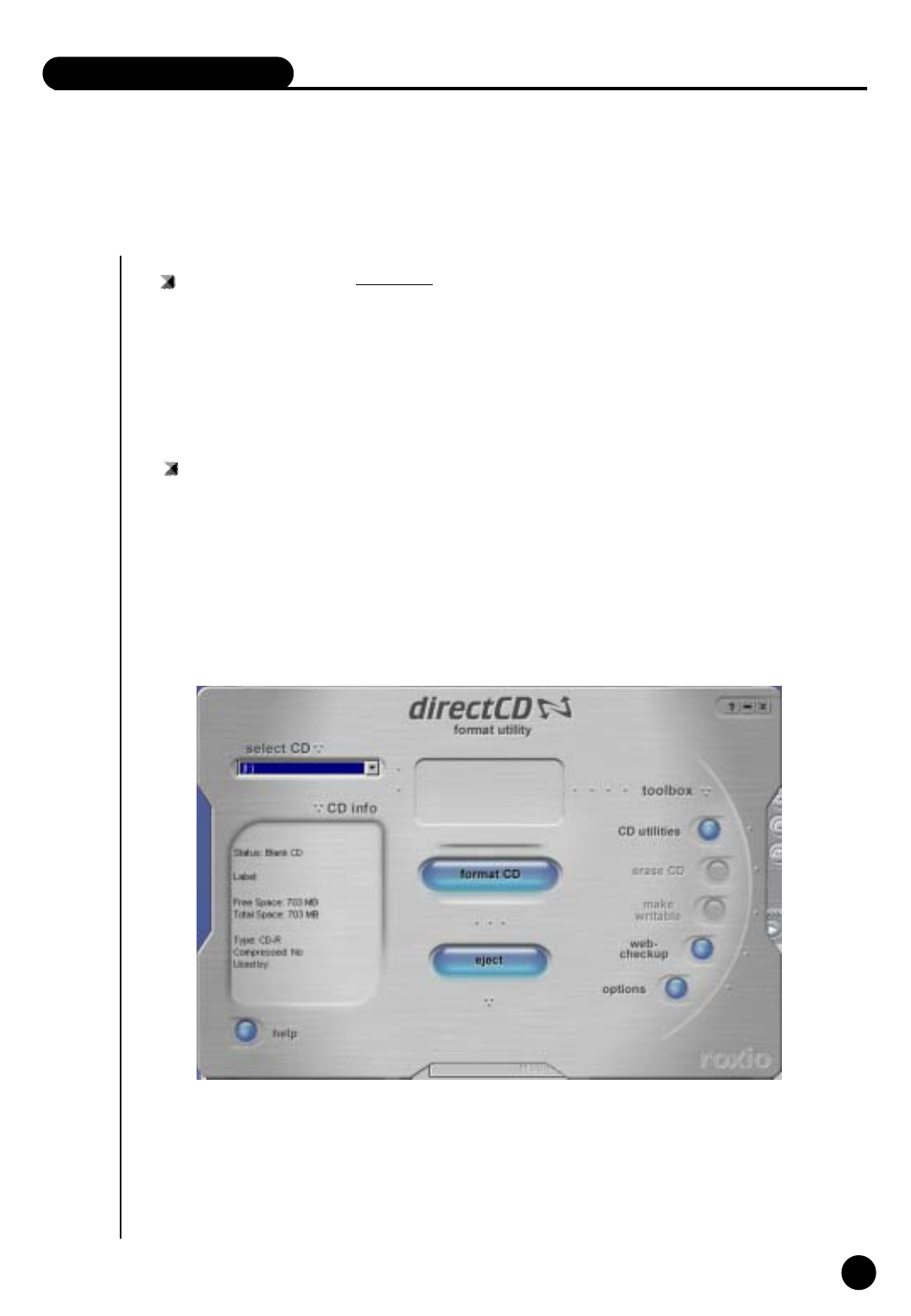
② Insert empty CD-R/RW media and click [Format CDR/CDRW]
(If CD-R/RW drive is set as “auto” Direct CD program will run automatically.)
③ Check if CD-R/RW is selected when the Direct CD format utility comes up, Direct CD and
click [format CD]
76
76
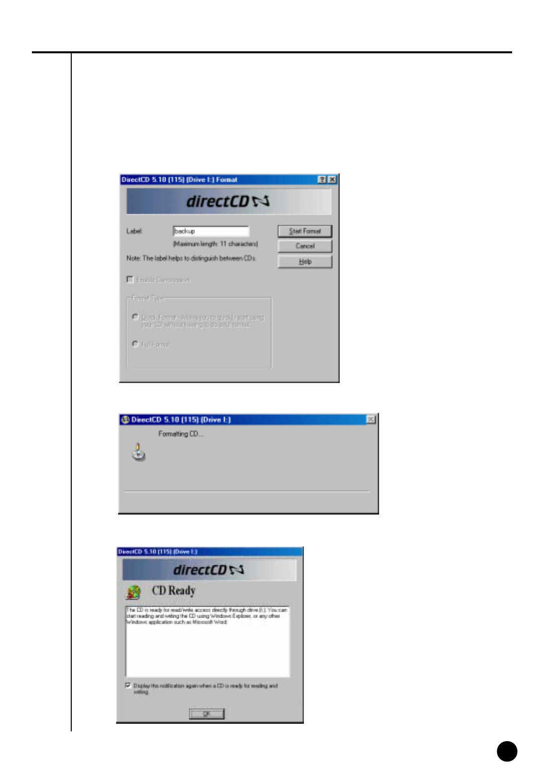
⑤ “Formatting CD..” Window will appear and starts CD-R/RW media format.
④ When you see a “drive format” window, input a name to “Label”
and click [Start Format] button
⑥ When the format is done, below window will appear saying “CD Ready”. Then click [OK]
77
77
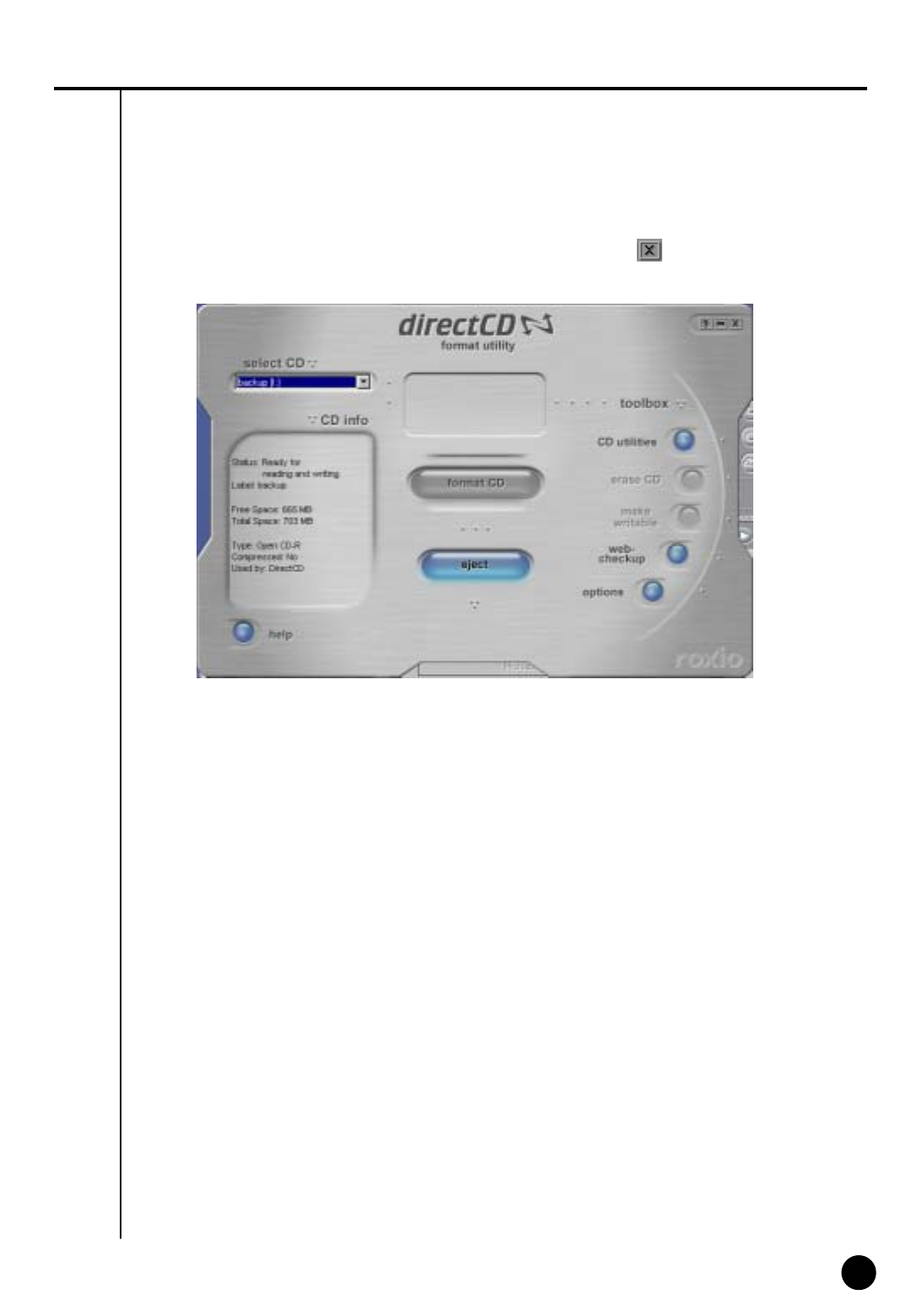
⑦ If Direct CD format utility windows come up, click this button to close..
( Do not click [eject] button.)
⑧ Select the type, time, and camera for backup and click [OK] button.
“WRITE” LED of CD-R/RW will be turned on till CD writing is done.
Do not press button in CD-R/RW
⑨ Once the backup is done, click “Eject” button in CD-R/RW
78
78
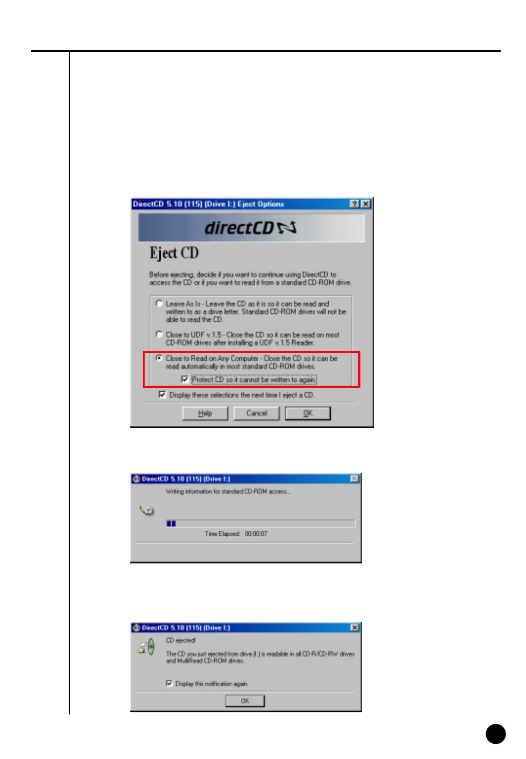
⑩ If “Direct CD Eject Options” window comes up, select “Close to Read on Any Computer” and
click ”OK”
(If possible select “Protect CD so it cannot be written to again” not to re-write on CD-RW)
⑪ Below window will appear to close CD-R/RW media. Wait until this procedure ends.
⑫ Once the above procedure ends below window will appear.
Then eject the CD-R/RW media and click [OK] button.
79
79
3
System setup for Audio function
IV. 부록
[Audio volume setup for voice recording]
Prior to recording voice, you need to first control audio volume for microphone.
Go to ‘Start ÆProgram ÆApplication ÆEntertainment ÆVolume Control’
Setup
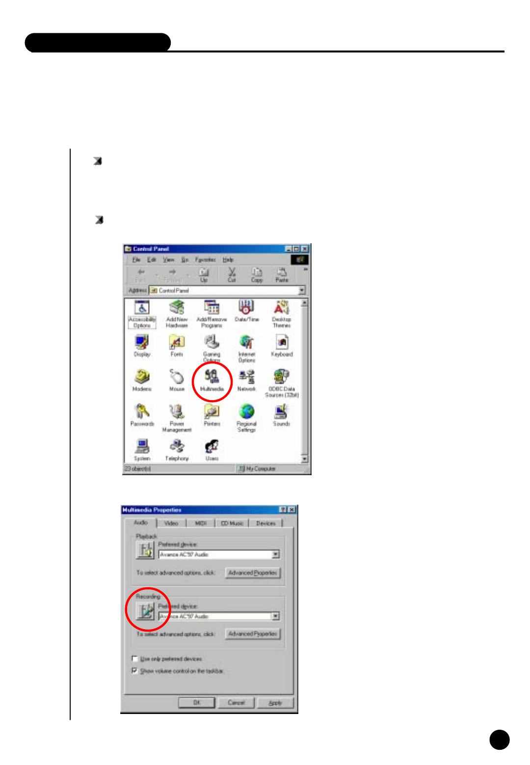
① Execute ‘Multimedia’ in Windows control pannel.
② Click “Recording” in Multimedia properties by clicking “Recording”button.
80
80
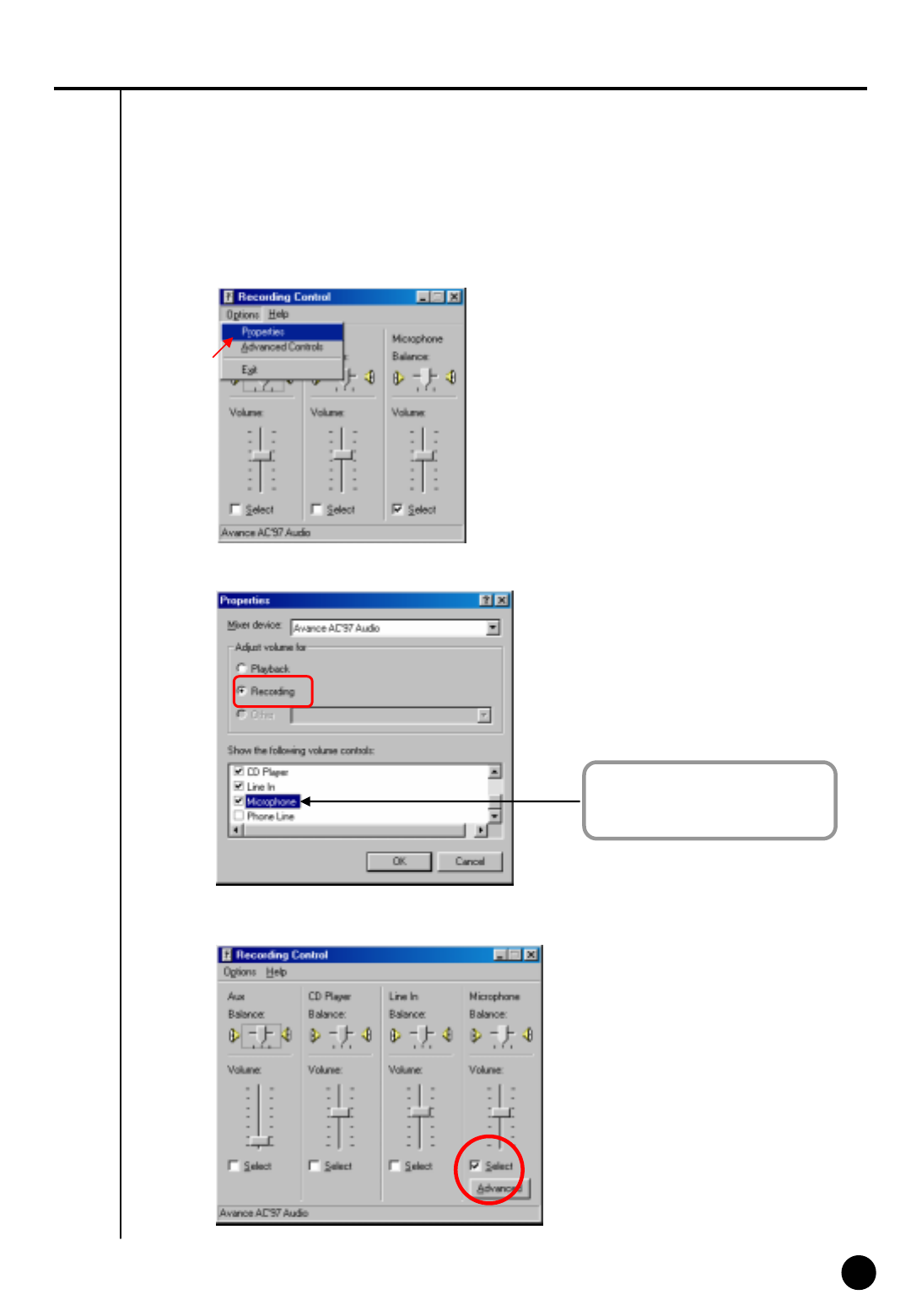
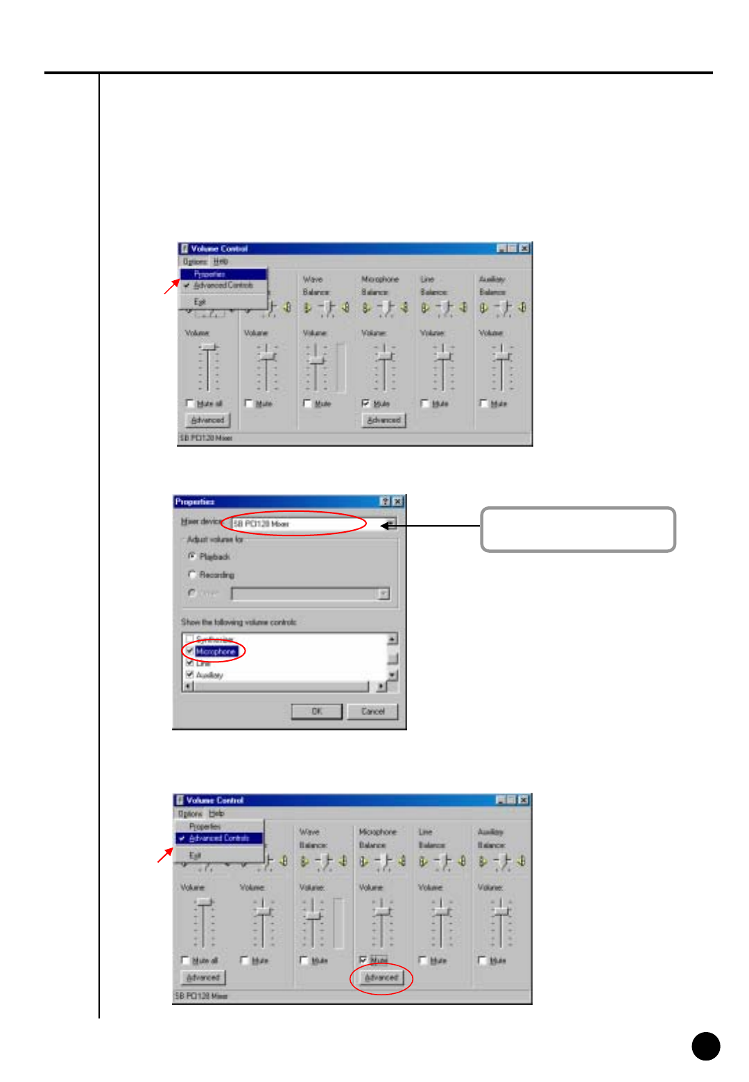
③ If the Recording window appear, go to ‘Option->Properties’
④ Select ‘Microphone’ in ‘Properties’ window and click ‘OK’.
⑤ If you click [OK] below ‘Microphone balance’ will appear in the ‘volume Control’ window.
In order to use voice recording
function “Microphone” should be
set from “Properties” tap.
81
81
!
![Notice]
If you don’t tick on the check box of ‘Microphone’, audio recording will
not work properly..
For proper use of Audio recording and two-way audio function above
setting should be made both Center and Site.
PC setup for use of Microphone from advanced mode
▶ For audio recording following volume setup should be made for microphone.
▶When the audio input through microphone is weak even in the maximized volume you can amplify
the audio input by adjusting as follows.
Setup
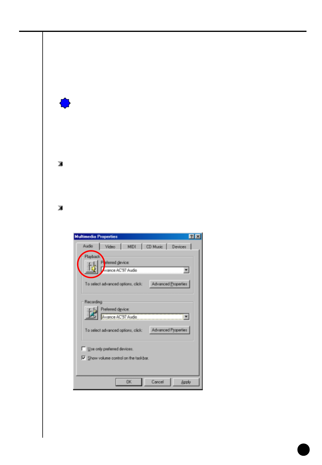
① Execute ‘volume control’ window by following “control panel-> Multimedia-> properties’
82
82
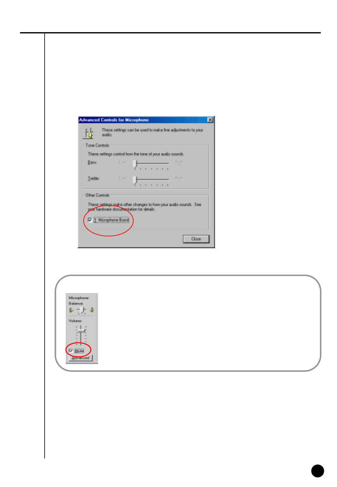
③In order to use voice recording function “Microphone” should be set from “Properties” tap.
④You can go to ‘Advanced Controls for Microphone’ by clicking ‘Advanced’ on ‘Microphone’
taps in ‘Volume Controls’.
②Go to ‘Options ÆProperties’ then, below window will appear.
Soundcard mixer is installed
in the system.
83
83
⑤Please adjust the options to fit into your system and check the sound output from ‘Other Controls’.
• Click on ‘Mute’ which is circled on the left picture, if you do not want any voice
output from a speaker that was inputted to the microphone but record the voice only
or if you just want the output of searched voice from the speaker only when
installing a microphone.
• When the system doesn’t support ‘Microphone Boost’ function, ‘Advanced’ button
may not appear. In that case you can solve it by using a more sensitive amplified
microphone.
• Sound card must be installed properly to use voice recording function.
☞
☞[Note]
84
84
4
Serial cable connection (input)
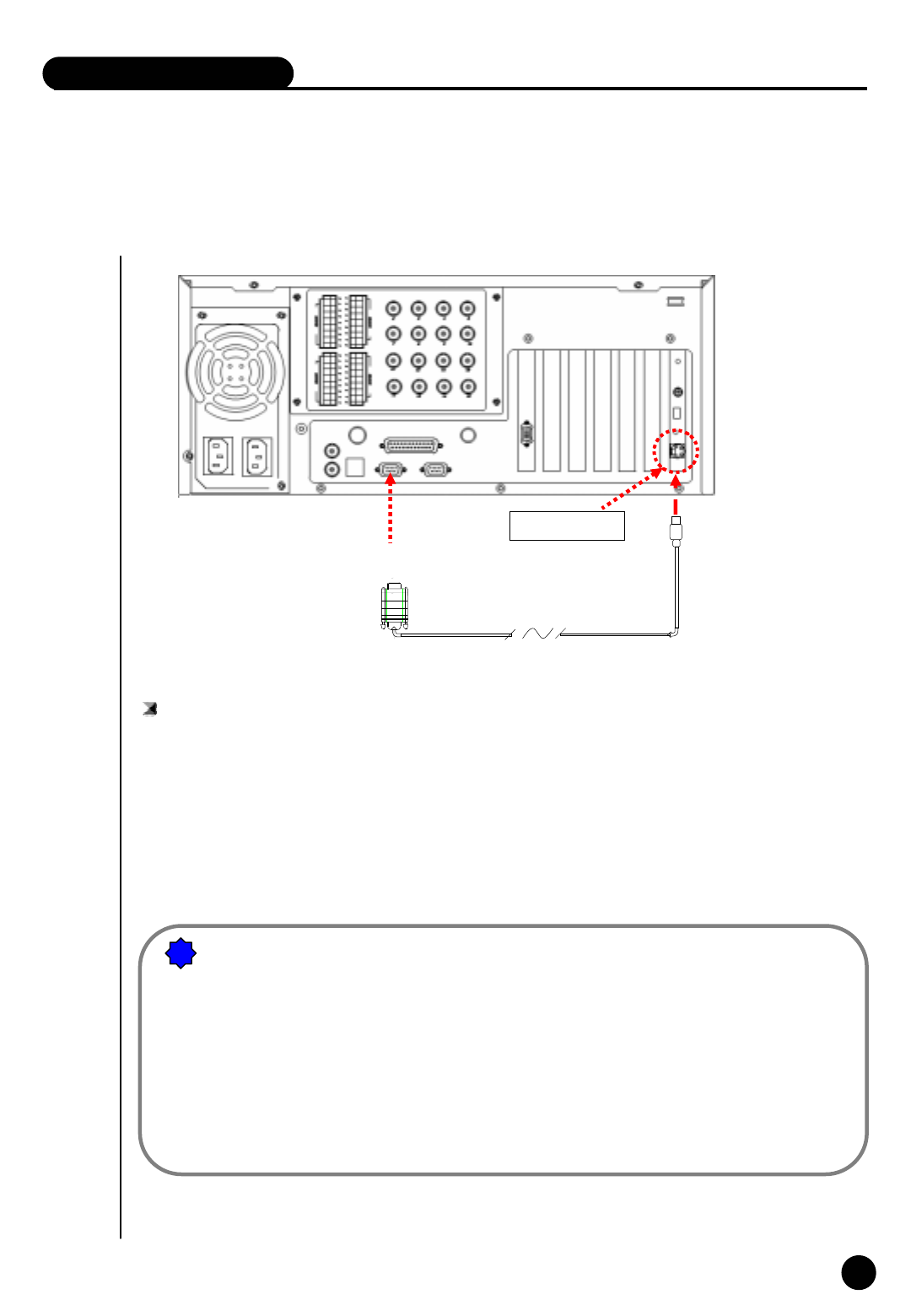
RS-232C Port
Connect to COM 1 Port
(9 PIN)
[Function of RS-232 Serial connection]
• Enables Sensor function
• Enables Control function
• Enables P/T/Z function
• Enables Watch Dog function
• Enables External monitor output function
(Depends on model)
[Notice]
Serial Cable must appropriately connected to COM1 Port and RS-232 in order to use the
function above.
Control and Sensor, part of the product which is not supported by P/T/Z may not include
Serial Cable. Connection will be provided only for the product that supports control and
sensor.
If Serial Cable is not connected appropriately, system may not operate properly and even
damage the system. Also, it may not recovered automatically.
(Product which is not supported by Control and Sensor, P/T/Z function uses its own auto
recovery function.)
!
!
IV. Appendix
85
85
5
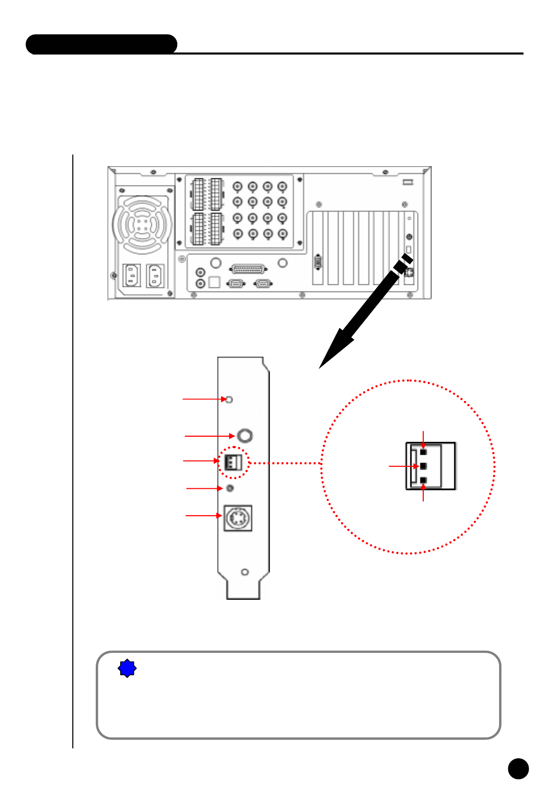
PAN/TILT Drive connection
[Notice]
1) Be cautious about (+),(-) of the signal line.
Wrong connection of the signal line might cause damage.
2) Please contact our distributor if you use other brand’s RX Receiver.
RUN LED
EXTERNAL MONITOR
RS-422 connection
(from RX-Receiver)
RS-232 Connection
(from Com1 port)
Remote Controller
Receiver
No Use
SIGNAL
( + )
SIGNAL ( - )
!
!
IV. Appendix
86
86
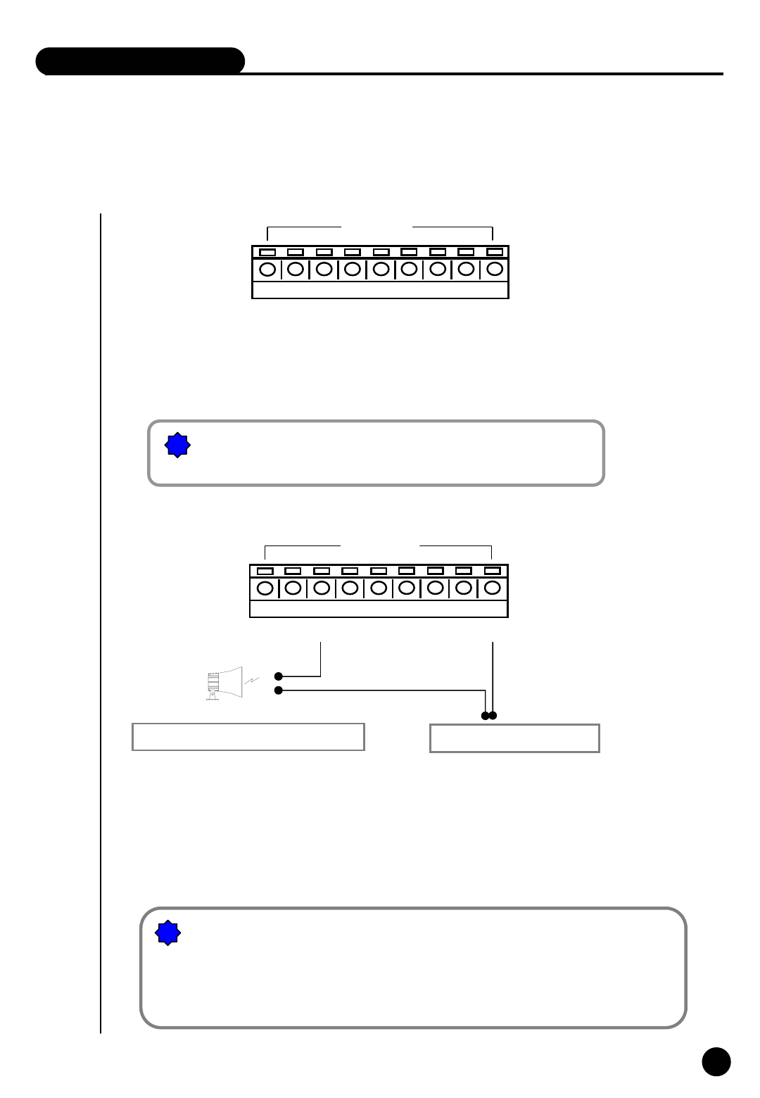
6
External Sensor input and Control output connection
IV. Appendix
12345678
SENSOR
G
One line of signal line for sensors such as infrared rays, heat perception, magnetic
etc, should be connected to COM connector and the other line is connected to any
sensor 1-8 connector which you selected.
!
![Notice]
Please use individual adapter for each sensor’s power input.
12345678G
CONTROL
External Power (DC 12V)
(-)
(+)
Alarm, Siren, relay etc.
[Notice]
The power of adapter should be no more than 12V and 300mA.
Additional external relay should be used to control on and off of device powered by
AC input.
• When the linked connection and control by external sensor works linked control output connects
to COM port. (setup->hardware->alarm) Control output related by external sensor
☞it remains “NC” condition normally
☞but it switches to “NO” when it starts sending control signal
!
!

87
87
Any defect under normal use within the warranty service period we give you free repair service
according to the warranty sheet.
We charge you with the fee of parts and service despite free warranty service period.
1. Any breakage made without care.
2. Breakage or trouble made by natural disaster.
3. Breakage or trouble made by breaking the product guide or manual.
4. Breakage or trouble made by wrong power voltage or frequency.
5. When you want to reassemble for full system or replace parts within warranty service period.
6. When unauthorized engineer modified or made damage on the product trying to repair it, we may charge ]
you with the fee.
We don’t support the breakage after warranty service period. If the customer wants to get it repaired,
we charge them with the fee.
¾This warranty sheet may not be provided again.
¾Please get this sheet filled when you purchase the product.
¾You should show this warranty service sheet when you get a warranty service.
Warranty Guide
Warranty Guide
Address
Name
Customer
1 year from the purchasing date
Warranty Period
Date you purchased
Distributor
Product Serial Number
Product & model name
Product Warranty Service Sheet
This product has passed thorough quality control and test, and if this get broken during normal
use we provide 12 months warranty service.
Warranty Guide
Check this warranty sheet first.
Please contact the distributor after checking out any defect in the product.
The standard for repairing, replacement or reimbursement follows Customer
Warranty Content