KOMPLEX SML Smart RFID System User Manual Manual SML June05
KOMPLEX Smart RFID System Manual SML June05
UserManual.wiki
>
KOMPLEX
>
SML User Manual
manual
Navigation menu
Upload a User Manual
Namespaces
Wiki Guide
HTML
PDF
Info
Views
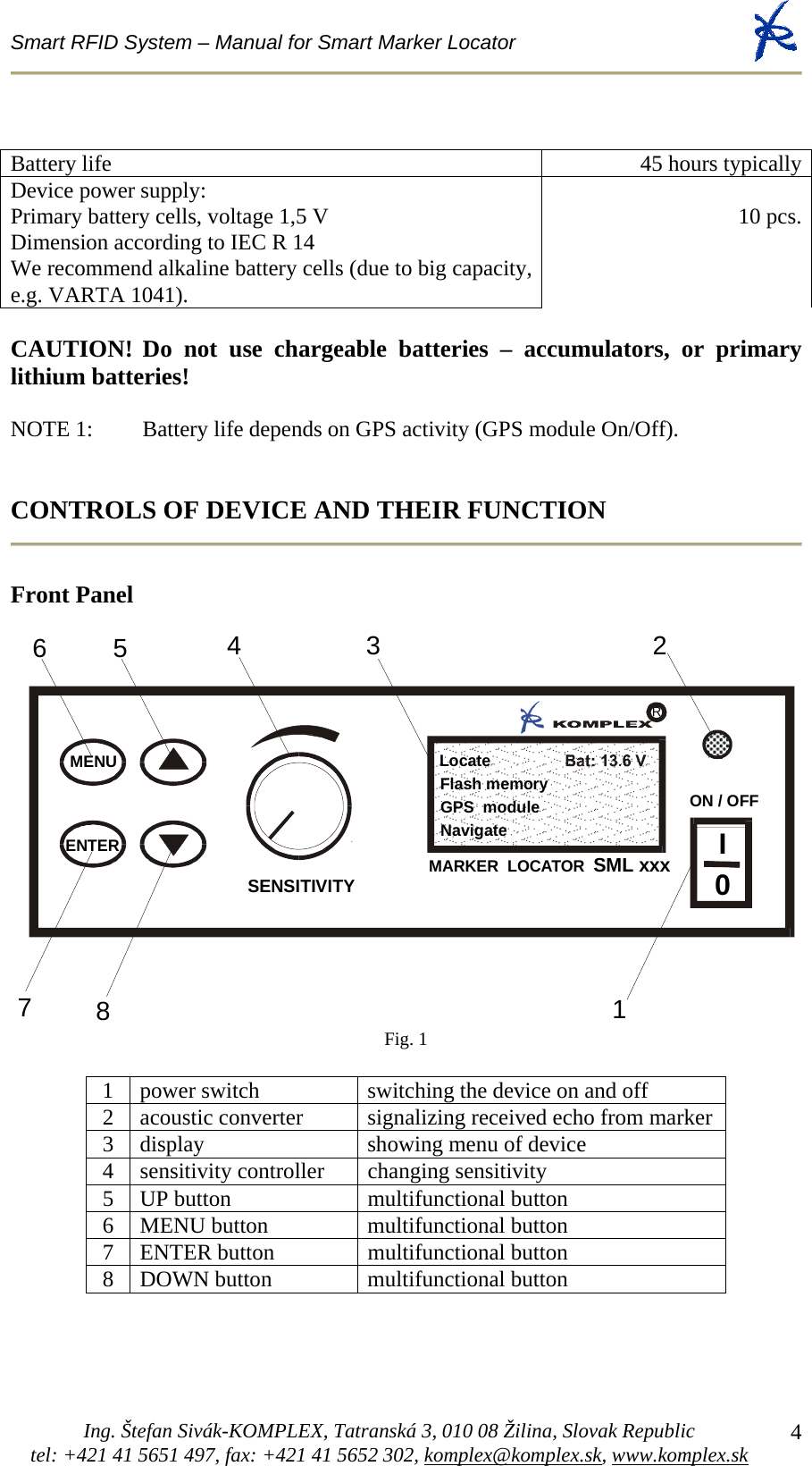
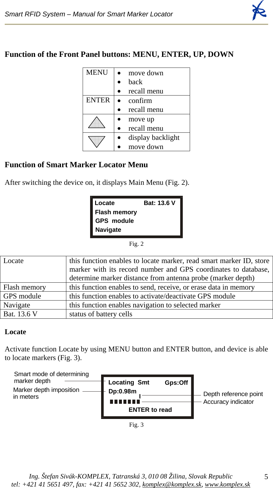
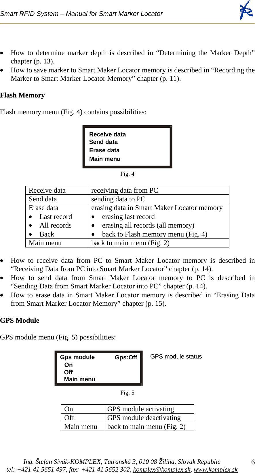
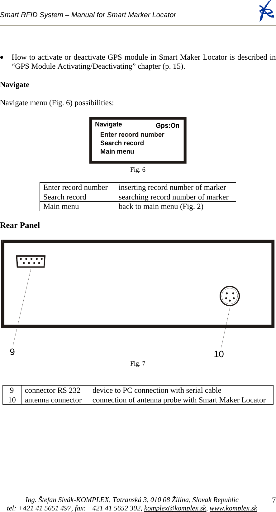
User Manual
Discussion / Help
Navigation