KONICA MINOLTA AERODRP5 AeroDR SYSTEM 2 User Manual Short Term Confidential 2
KONICA MINOLTA, Inc. AeroDR SYSTEM 2 Short Term Confidential 2
Contents
- 1. (Short-Term Confidential) User Manual_1
- 2. (Short-Term Confidential) User Manual_2
(Short-Term Confidential) User Manual_2

45
Chapter 3
General Operations
Thischapterdescribesgeneraloperationmethodsofthisdevice.
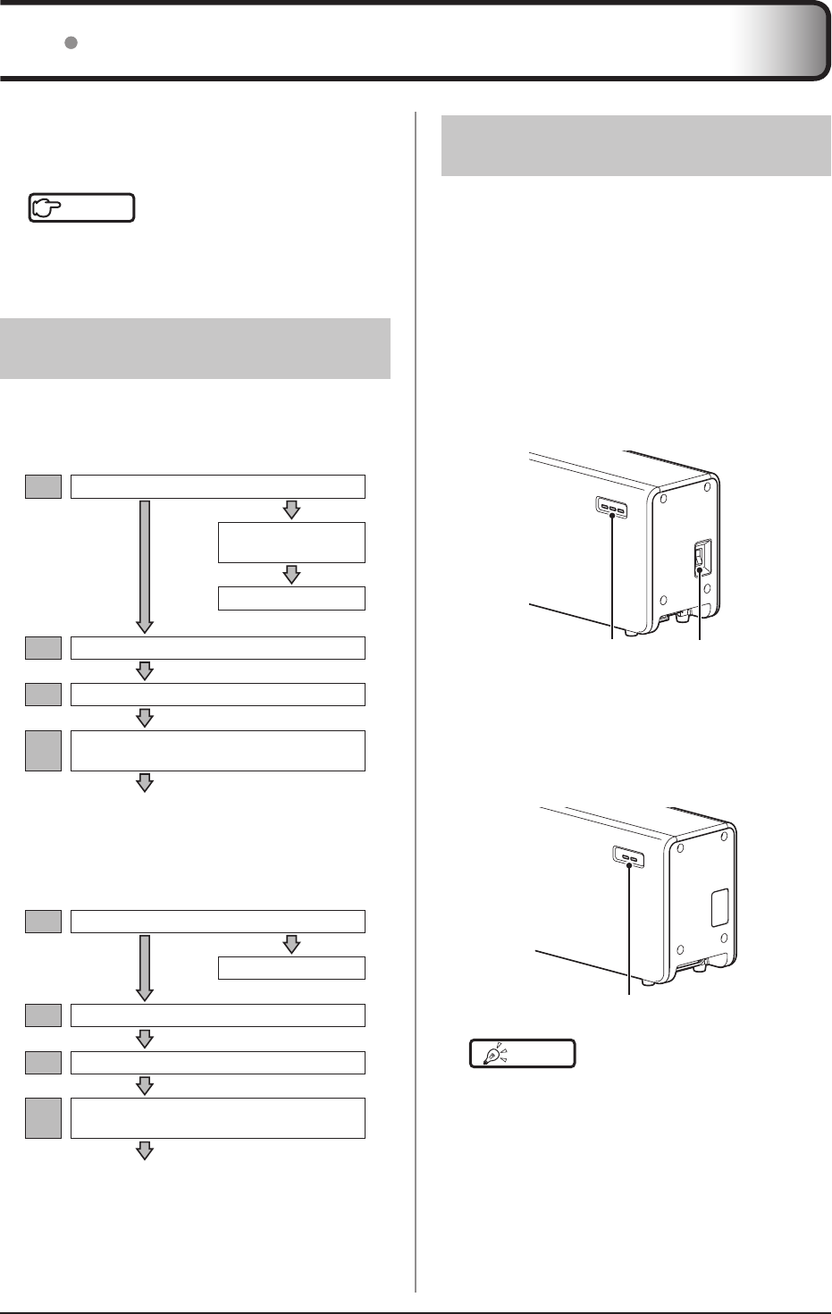
46
31 Startup and shutdown
312 Startup of this device
Thestartupmethodsofthisdeviceareasfollows.
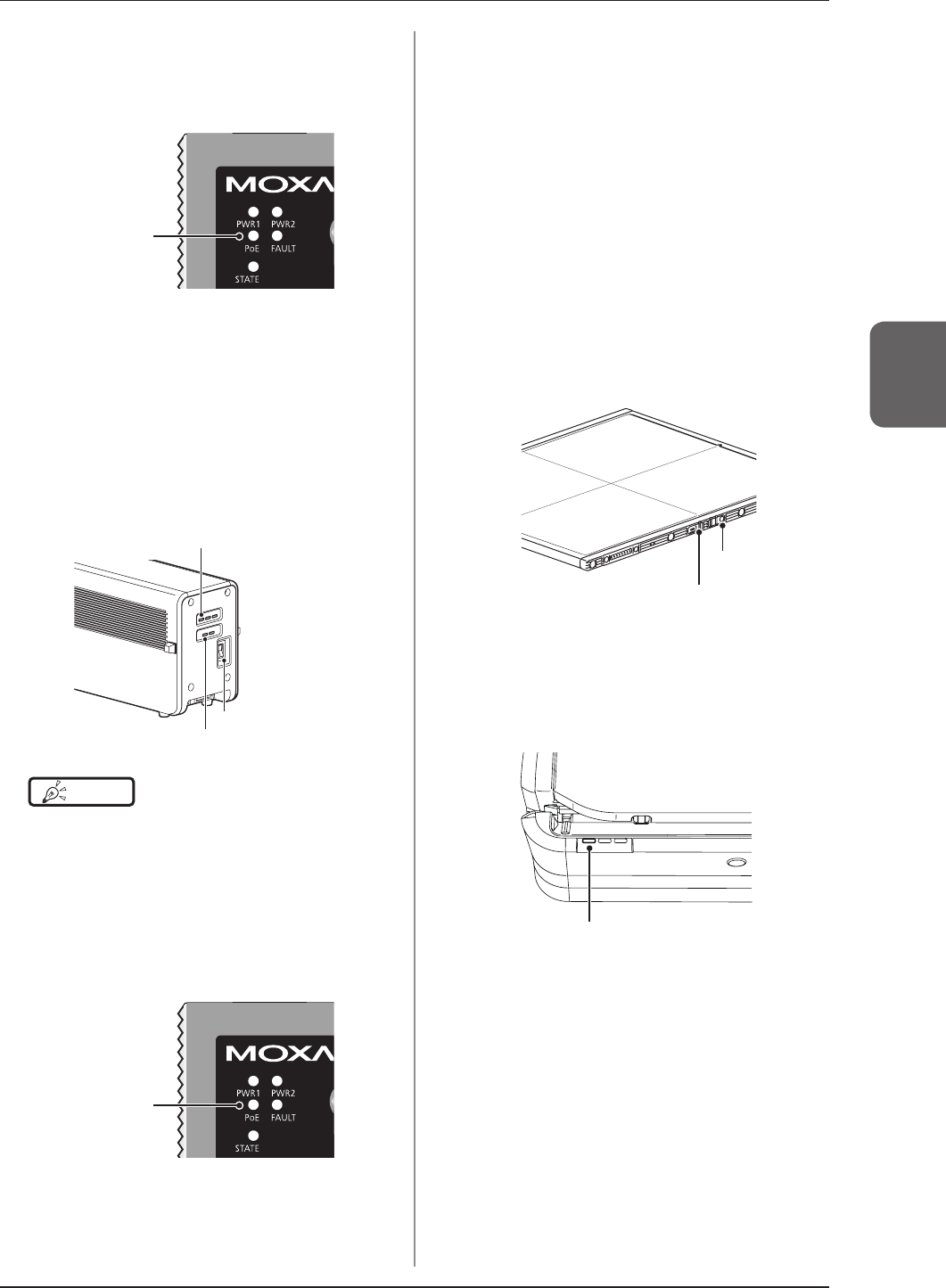
AeroDR Interface Unit, AeroDR Generator
Interface Unit and Access Point
• ThestartupmethodsoftheAeroDRInterface
Unit,AeroDRGeneratorInterface UnitandAc-
cessPointareasfollows.
1 Turn the power switch of the AeroDR In-
terface Unit on, and conrm that the LED
(green) lights
PowerswitchLED(green)
2 When the power switch of the AeroDR
Interface Unit is turned on, power is also
supplied to the AeroDR Generator Inter-
face Unit, and the LED (green) will ash
LED(green)
HINT •••••••••••••••••••••••••••••••••••••
• InAeroSyncmode,theAeroDRGeneratorInterface
Unitisnotused.
•••••••••••••••••••••••••••••••••••••••••••••••••••••
Normally,thisdeviceisusedwiththepoweron.
Whennotusedformorethan1day,operatethestart-
up/shutdownasfollows.
Reference
•••••••••••••••••••••••••••••••••••••
•
Refertothe"OperationManual"oftheimageprocessing
controllerregardingon/offfortheimageprocessingcontroller.
•••••••••••••••••••••••••••••••••••••••••••••••••••••
311 Startup sequence of this
device
Thestartupsequenceofthisdeviceisasfollows.
When using AeroDR Interface Unit
1AeroDRInterfaceUnit
AeroDRGenerator
InterfaceUnit
AccessPoint
2
Imageprocessingcontroller
3AeroDRDetector
4AeroDRBatteryCharger/
AeroDRBatteryCharger2
ConrmthattheAeroDRDetectorisreadyfor
useontheimageprocessingcontroller.
When using AeroDR Interface Unit2
1AeroDRInterfaceUnit2
AccessPoint
2
Imageprocessingcontroller
3AeroDRDetector
4AeroDRBatteryCharger/
AeroDRBatteryCharger2
ConrmthattheAeroDRDetectorisreadyfor
useontheimageprocessingcontroller.
3.1Startupandshutdown
47
Chapter 3
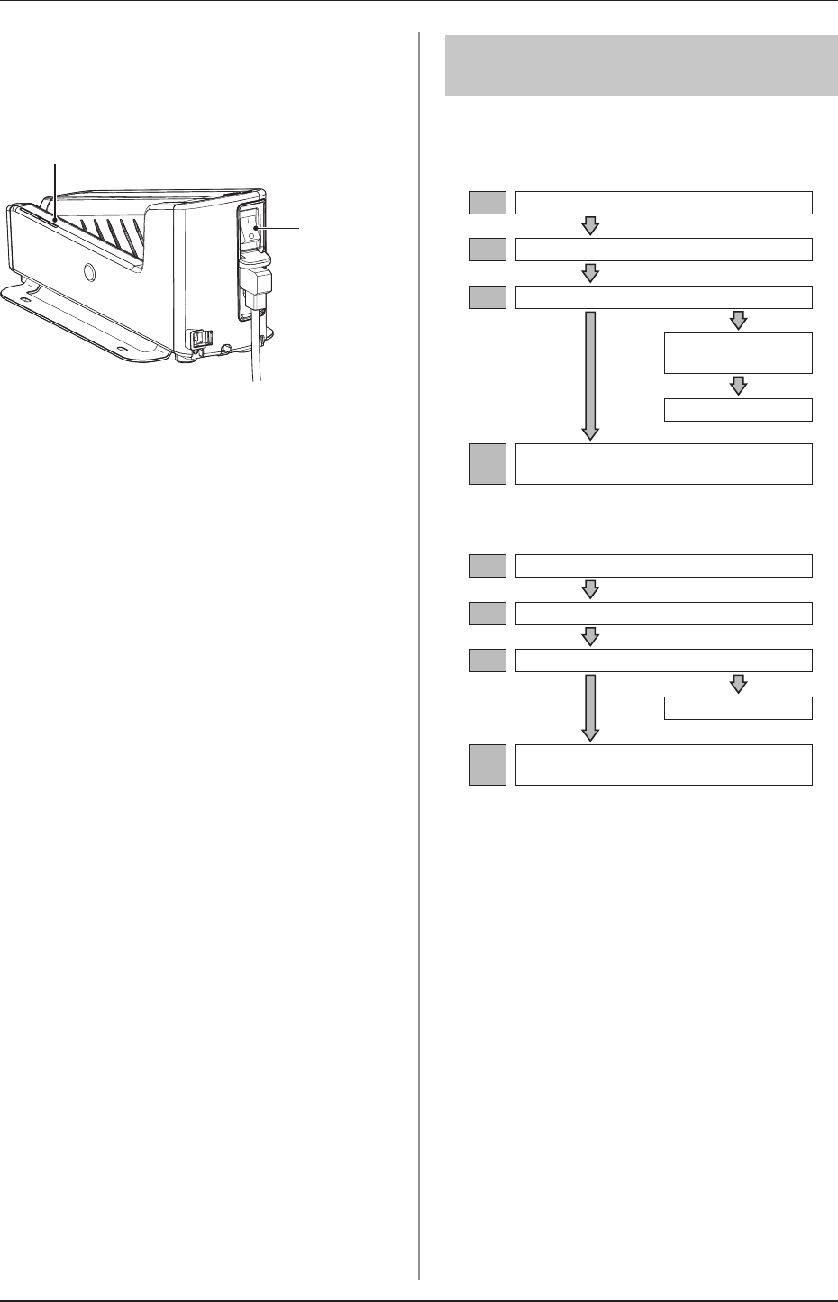
3 When the power switch of the AeroDR
Interface Unit is turned on, power is sup-
plied to the Access Point, and the LED
(umber) on the Access Point will light
LED(umber)
AeroDR Interface Unit2 and Access Point
• ThestartupmethodsoftheAeroDRInterface
Unit2andAccessPointareasfollows.
1 Turn the power switch of the AeroDR In-
terface Unit2 on, and conrm that the De-
tector Connection LED (green) and Gen-
erator Interface LED (green) light
Powerswitch
DetectorConnectionLED(green)
GeneratorInterfaceLED(green)
HINT •••••••••••••••••••••••••••••••••••••
• IttakestimefortheGeneratorInterfaceLED(green)
tolight.
•••••••••••••••••••••••••••••••••••••••••••••••••••••
2 When the power switch of the AeroDR
Interface Unit2 is turned on, power is sup-
plied to the Access Point, and the LED
(umber) on the Access Point will light
LED(umber)
Image processing controller
• Starttheimageprocessingcontrollerbyturning
thepowerswitchoftheimageprocessingcon-
trolleron.
AeroDR Detector
• IftheAeroDRDetectorisinsertedintotheAero-
DRBatteryCharger/AeroDRBatteryCharger2
withawirelessconnection,theAeroDRDetector
shouldberemoved.
• Forawiredconnection,conrmthattheAeroDR
UFCableortheAeroDRI/FCableisconnected
securelytothewiredconnectionconnectorof
theAeroDRDetector.
• Next,pressthepowerswitchoftheAeroDRDe-
tectorfor2secondsandturniton,andconrm
thattheLED(green)isslowlyashingorlit.
LED(green)
Powerswitch
AeroDR Battery Charger
• Whenthepowercableisconnectedtothewalloutlet,
poweroftheAeroDRBatteryChargeristurnedon.
ConrmthattheLED(green)isslowlyashing.
LED(green)
3.1Startupandshutdown
48
AeroDR Battery Charger2
• Turnthe powerswitchoftheAeroDR Battery
Charger2on,andconrmthattheLED(green)
isslowlyashing.
LED(green)
Powerswitch
313 Shutdown sequence of
this device
Thestartupsequenceofthisdeviceisasfollows.
When using AeroDR Interface Unit
1AeroDRDetector
2
Imageprocessingcontroller
3AeroDRInterfaceUnit
AeroDRGenerator
InterfaceUnit
AccessPoint
4AeroDRBatteryCharger/
AeroDRBatteryCharger2
When using AeroDR Interface Unit2
1AeroDRDetector
2
Imageprocessingcontroller
3AeroDRInterfaceUnit2
AccessPoint
4AeroDRBatteryCharger/
AeroDRBatteryCharger2
3.1Startupandshutdown
49
Chapter 3
314 Shutdown of this device
Theshutdownmethodsofthisdeviceareasfollows.
AeroDR Detector
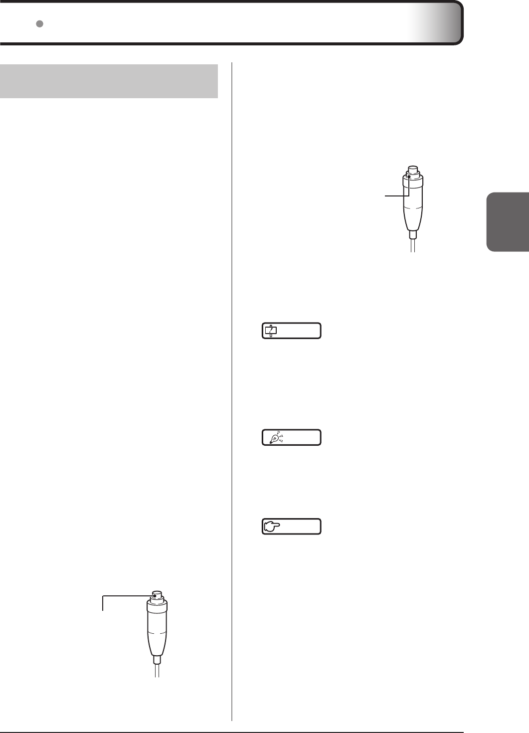
• PressthepowerswitchoftheAeroDRDetector
for5secondstoturnitoff,andconrmthatthe
LED(green)isturnedoff.
LED(green)
Powerswitch
Image processing controller
• Turnthepowerswitchoftheimageprocessing
controlleroff,andshutdowntheimageprocess-
ingcontroller.
AeroDR Interface Unit, AeroDR Generator
Interface Unit and Access Point
• TheshutdownmethodsoftheAeroDRInterface
Unit,AeroDRGeneratorInterfaceUnitandAc-
cessPointareasfollows.
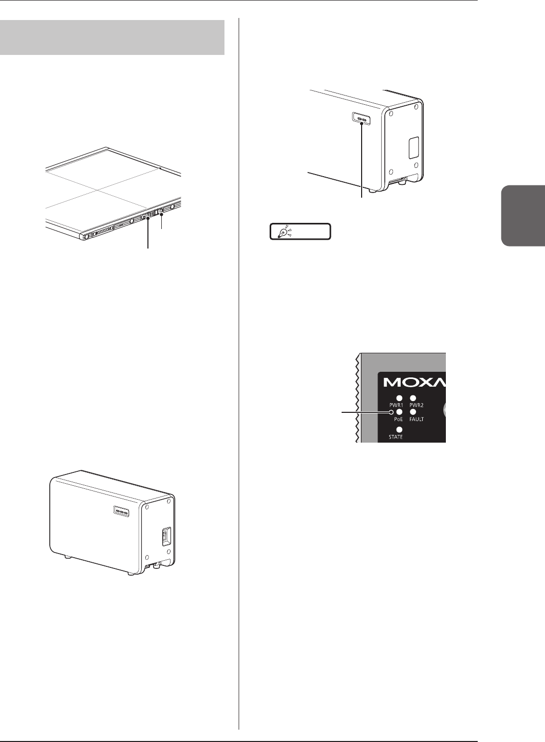
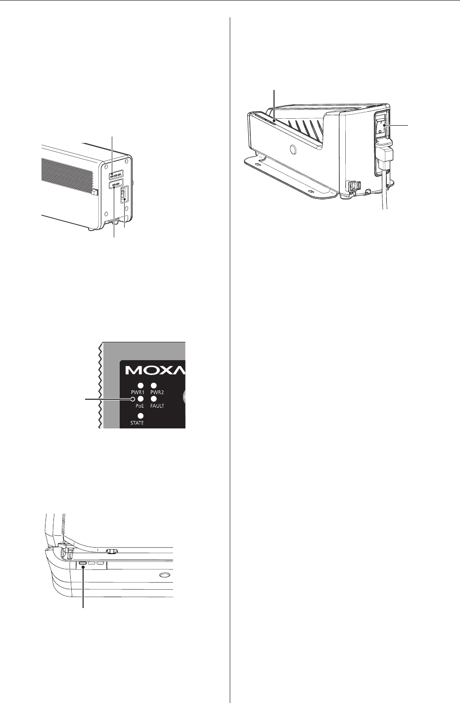
1 Turn the power switch of the AeroDR In-
terface Unit off, and conrm that the LED
(green) is turned off
2 When the power switch of the AeroDR
Interface Unit is turned off, power supply
to the AeroDR Generator Interface Unit is
terminated The LED (green) will turn off
on the AeroDR Generator Interface Unit
LED(green)
HINT •••••••••••••••••••••••••••••••••••••
• InAeroSyncmode,theAeroDRGeneratorInterface
Unitisnotused.
•••••••••••••••••••••••••••••••••••••••••••••••••••••
3 When the power switch of the AeroDR In-
terface Unit is turned off, power supply to
Access Point is terminated The LED (um-
ber) on the Access Point will turn off
LED(umber)
3.1Startupandshutdown
50
AeroDR Interface Unit2 and Access Point
• TheshutdownmethodsoftheAeroDRInterface
Unit2andAccessPointareasfollows.
1 Turn the power switch of the AeroDR In-
terface Unit2 off, and conrm that the De-
tector Connection LED (green) and Gener-
ator Interface LED (green) are turned off
Powerswitch
DetectorConnectionLED(green)
GeneratorInterfaceLED(green)
2 When the power switch of the AeroDR
Interface Unit2 is turned off, power sup-
ply to the Access Point is terminated The
LED (umber) on the Access Point will turn
off
LED(umber)
AeroDR Battery Charger
• Whenthepowercableisremovedfromthewall
outlet,thepoweroftheAeroDRBatteryCharger
isturnedoffandtheLED(green)isturnedoff.
LED(green)
AeroDR Battery Charger2
• Turnthe powerswitchoftheAeroDR Battery
Charger2off,andconrmthattheLED(green)
isturnedoff.
LED(green)
Powerswitch
51
Chapter 3
4 Push the S-SRM’s hand switch up to the
second level to perform exposure
• ExposureisperformedfromtheX-raydeviceto
produceX-rayimages.
• Whentheexposureiscompleted,imagesare
storedintheAeroDRDetectorandwillthenbe
convertedtodigitaldataandsenttotheimage
processingcontrollersequentially.
Secondstageswitch
5 Check that the exposed image is dis-
played on the image processing control-
ler
IMPORTANT
•••••••••••••••••••••••••••••••••••••
• TheAeroDRDetectorisprecisionequipment,and
thereforeimpactorvibrationduringradiographyorim-
agetransfermayaffecttheimagequality.Becareful
whenhandlingtheAeroDRDetectorduringandjust
afterradiography.
•••••••••••••••••••••••••••••••••••••••••••••••••••••
HINT •••••••••••••••••••••••••••••••••••••
• IftheAeroDRDetectorremainsunusedforalongtime
(timecanbeset)ittransitionstothesleepmode.
• Whentheimageprocessingcontrollerisreadytoex-
pose,itrecoversfromthesleepmode.
•••••••••••••••••••••••••••••••••••••••••••••••••••••
Reference
•••••••••••••••••••••••••••••••••••••
• Regardingtheoperationoftheimageprocessingcon-
troller,refertothe"OperationManual"oftheimage
processingcontroller.
•••••••••••••••••••••••••••••••••••••••••••••••••••••
321 Exposure
Exposurewiththisdeviceisperformedwiththefollow-
ingprocedure.
Exposure under the basic connection ex-
ample
1
Perform examination registration with the
image processing controller
2 Check that this device is ready to expose
images, and then prepare for the expo-
sure
3 Push the exposure switch of the X-ray de-
vice to perform the exposure
• Whentheexposureiscompleted,imagesare
storedintheAeroDRDetectorandwillthenbe
convertedtodigitaldataandsenttotheimage
processingcontrollersequentially.
4 Check that the exposed image is dis-
played on the image processing control-
ler
Exposure under the S-SRM connection ex-
ample
1 Perform examination registration with the
image processing controller
2 Check that this device is ready to expose
images, and then prepare for the expo-
sure
3 Push the S-SRM’s hand switch to the rst
stage
• Theexposurepreparationsignalissenttothe
X-raydevice.
Firststageswitch
32 Operation of AeroDR Detector
3.2OperationofAeroDRDetector
52
322 AeroDR Detector orientation
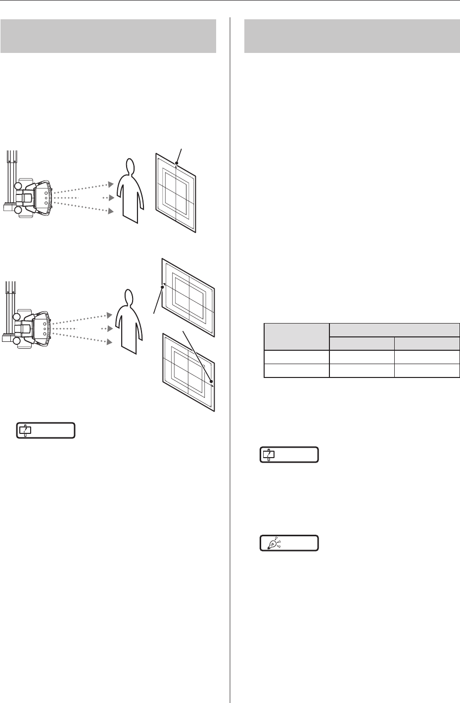
ChangetheorientationoftheAeroDRDetectorac-
cordingtotheexposurebodypart.
Exposewiththetriangularmarkupwardwhenexpos-
inginportrait,andwiththetriangularmarktotheside
whenexposinginlandscape.
When exposing in portrait
X-ray
X-raydevice
Thetriangularmarkisupward
When exposing in landscape
X-ray
X-raydevice
Thetriangular
markistotheleft
orright
IMPORTANT
••••••••••••••••••••••••••••••••••••
• Thesidewiththetriangularmarkistheexposuresur-
face.
• Whenexposing inlandscape,the directionof the
triangularmarkissetaccordingtoexposureenviron-
ment.
• Radiographyisnotallowedonasubjectinahorizon-
talpositionwhenanAeroDR1717HQisused.
••••••••••••••••••••••••••••••••••••••••••••••••••••
323 Precautions for exposure
Duringexposuregiveadequateattentiontothefollow-
ingitems.
High-dose exposure
• Whenhigh-doseexposuresareperformedcon-
tinuously,afterimagesofthelastexposurewill
occasionallybevisible.Theaffectofafterimages
inthisdevicecanberesolvedbyleavinglonger
intervalsbetweenexposures,somaketheinter-
valsbetweenexposureslongerthanusualwhen
performinghigh-doseexposure.
• Duringhigh-doseexposure,continualuseofa
leadorothermarkeratthesamepositioncan
causeburninginoftheafterimage.Therefore,
avoidusingitinthesameposition.Also,ifimage
burn-inisvisible,runcalibration.
Exposure time
• Selectthemaximumexposuretimefrom0.7,1.7,
and3.2.
• AeroDRDetectorswhosemaximumexposure
timecanbesetto4.0,6.7,10.3areasfollows.
AeroDR
Detector
Serial Number
First four digits Number
AeroDR1417HQ A5DP 50198ormore
AeroDR1012HQ A5TE 51001ormore
• Theexposuretimeforactualexposuresshould
notexceedthemaximumexposuretimeyouhave
set.Otherwise,exposuremayfailorcorrectim-
agesmaynotbeabletobeobtained.
IMPORTANT
•••••••••••••••••••••••••••••••••••••
• Ifyouincreasethemaximumexposuretime,the
AeroDRDetectormaytakelongertoexitsleepmode.
• Setexposuretimetowithin0.8secondswhenthe
AeroSyncmodeisused.
••••••••••••••••••••••••••••••••••••••••••••••••••••
HINT •••••••••••••••••••••••••••••••••••••
• Usetheimageprocessingcontrollertosetthemaxi-
mumexposuretime.Insomecases,themaximum
exposuretimeisxedaccordingtotheX-raydevice.
Fordetails,contactKonicaMinoltatechnicalrepresen-
tatives.
• WhenusingImagePilotastheimageprocessingcon-
troller,itisnotpossibletochangethemaximumexpo-
suretime.
•••••••••••••••••••••••••••••••••••••••••••••••••••••
3.2OperationofAeroDRDetector
53
Chapter 3
Exposure switch
• Iftheexposureswitchremainshelddown,itmay
resultinanafterimagebecomingvisible.Once
exposureisnished,releasetheexposureswitch
immediately.
Grid
• Usethefollowinggridwhenexposing.
Griddensity 40lp/cmor
34lp/cm
Gridratio Variety
Convergence
distance
Variety
Angleerror
40lp/cm:1.0°orless
34lp/cm:1.7°orless
IMPORTANT
•••••••••••••••••••••••••••••••••••••
• ForanAeroDR1417Swithoutthe"1417S"identica-
tion,useagridwithagriddensityof34lp/cmandan
angleerrorof0.5°orless.
1417S
AeroDR P-12
( )
Identication
• Whenthe"AeroSyncmode"isused,useagridwitha
gridratioof8orless.
• Acappedgridisrecommendedwhenlayingthegrid
overtheAeroDRDetectoronthetabletoporforexpo-
surewiththeportableX-raydiagnosticdevice.
•••••••••••••••••••••••••••••••••••••••••••••••••••••
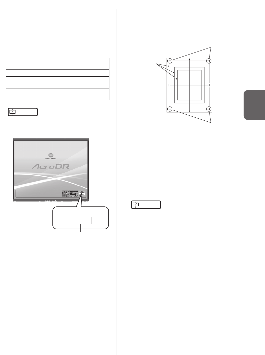
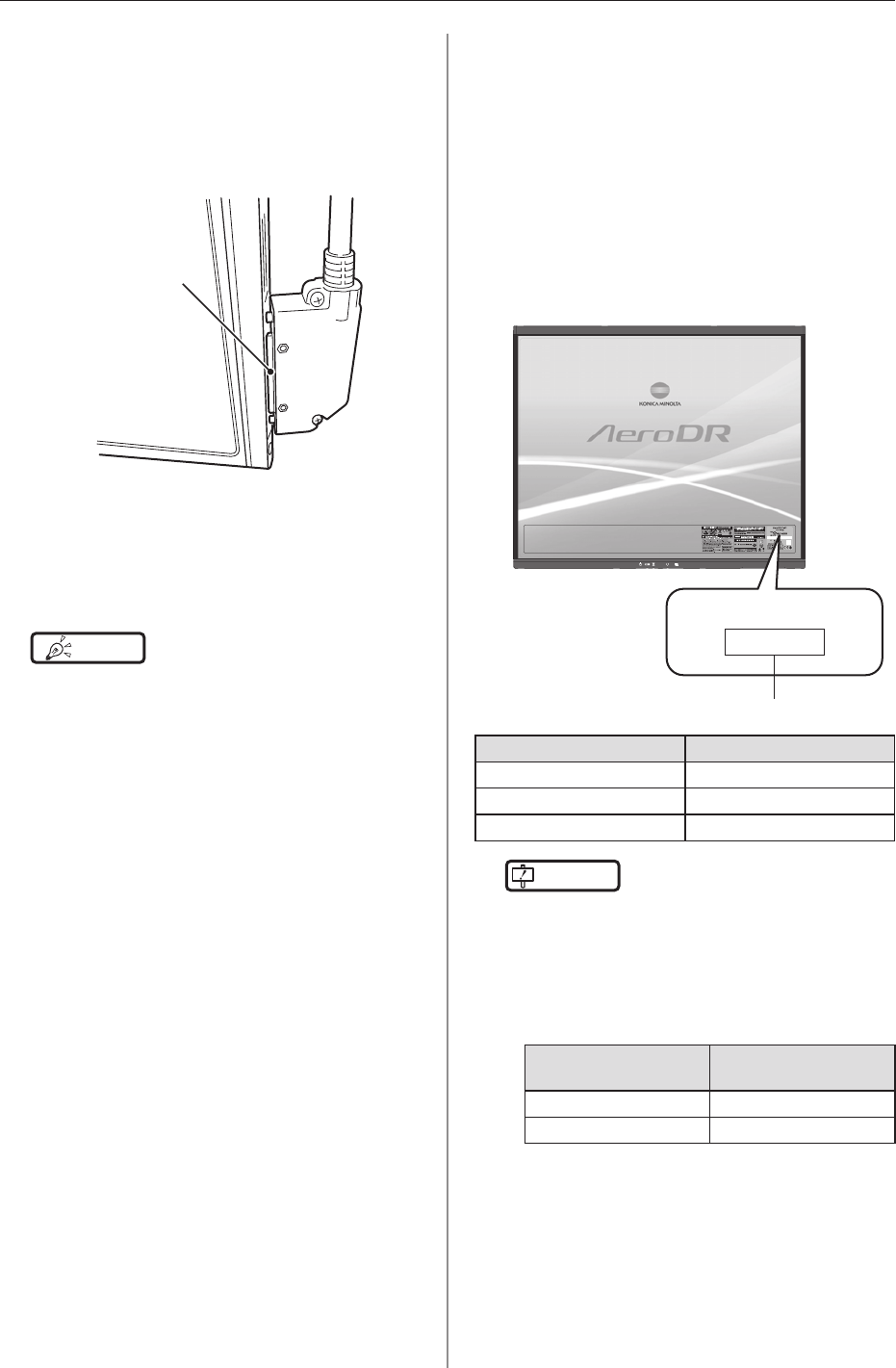
Exposure area
• ThesizelinesofAeroDRDetectorindicatethe
exposuresize.
• Duringexposure,placetheexposurebodypart
withinthewhitelinesonthefourcorners.
Whitelines
Whitelines
Sizelines
S-SRM connection
• WhenS-SRMconnectionisadopted,makesure
toperformexposureusingthehandswitchcon-
nectedtotheAeroDRInterfaceUnit2andAeroDR
GeneratorInterfaceUnit.
• Ifexposureisperformedusingthehandswitchon
theoperationpaneloftheX-raydevice,exposure
synchronizedtotheAeroDRSYSTEMisnotpos-
sible.
IMPORTANT
•••••••••••••••••••••••••••••••••••••
• Ifyourestarttheimageprocessingcontroller,also
restarttheAeroDRInterfaceUnit/AeroDRInterface
Unit2.
•••••••••••••••••••••••••••••••••••••••••••••••••••••
3.2OperationofAeroDRDetector
54
Wired connection
• Whenperformingexposurewithawiredconnec-
tion,fastenthewiredcablehorizontallytothe
wiredconnectionconnectoroftheAeroDRDetec-
tor.Ifconnectedatanangle,transverse(noise)
sometimesgetsintoacquiredimagesafterexpo-
sure.
Connectitsuchthat
thereisnospace.
Wireless communications environment
• Withawirelessenvironment,itispossiblethat
errorssuchasnowirelessconnection,wireless
communicationterminates,andlengthenedexpo-
surecycletimemightoccur.
HINT •••••••••••••••••••••••••••••••••••••
• Problemswithawirelesscommunicationsenviron-
mentcanoccurinthefollowingconditions:
– InstalledlocationoftheAccessPointisnotgood.
– Wheninsertedinthewallstand,table,orstretcher,
theopeninginthewallstandortableistoosmall
andthereisnopassagefortheradiowaves.
– Theradiowavesarenotemittedduetometalparts
closetotheantenna,whichchangestheantenna
characteristics.
– ForexposureswherethebodytouchestheAeroDR
Detectordirectly,theradiowavesarenotemitted
ifthebodycompletelycoverstheantennasposi-
tionedin2places.
– Otherdevicesusethesameradioband,andcause
interference.
•••••••••••••••••••••••••••••••••••••••••••••••••••••
AED (Automated External Debrillator)
• WhenanAED(AutomatedExternalDebrillator)
isused,movetheAeroDRDetectorawayfrom
thepatient.Highvoltageandhighcurrentmay
resultinabreakdownoftheAeroDRDetector.
The operating temperature environment of
AeroDR Detectors
• IfanAeroDRDetectorisleftclosetoorincontact
withaheatgeneratorsuchaselectriccarpet,its
safetydevicemaybeactivatedandtheAeroDR
Detectormayfailtoworkproperly.
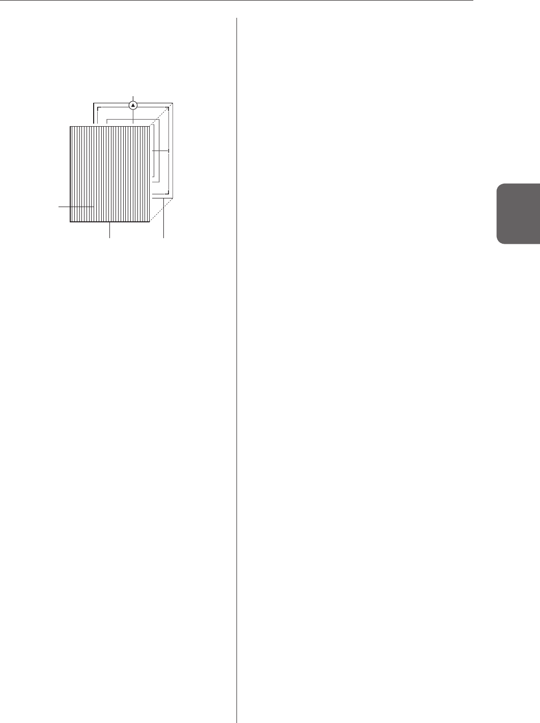
Identify the AeroDR Detector that users can
use in Aero Sync mode
• Conrmthatifthefollowingidenticationisinthe
AeroDRDetectorthatuserscanuseinAeroSync
mode.
( )
AeroDR P-11
1417HQ
Identication
AeroDR Detector Identication
AeroDR1417HQ 1417HQ
AeroDR1717HQ 1717HQ
AeroDR1012HQ 1012HQ
IMPORTANT
•••••••••••••••••••••••••••••••••••••
• UserscannotuseAeroSyncModeintheAeroDRDe-
tectorifitisAeroDR1417S.
• UserscannotuseAeroSyncmodeintheAeroDR
DetectoriftherstfourdigitsofitsSerialNumberare
showninthefollowingtableintheAeroDR1417HQor
AeroDR1717HQ.
AeroDR Detector SerialNumber that
cannot be used
AeroDR1417HQ A45Y
AeroDR1717HQ A54T
•••••••••••••••••••••••••••••••••••••••••••••••••••••
3.2OperationofAeroDRDetector
55
Chapter 3
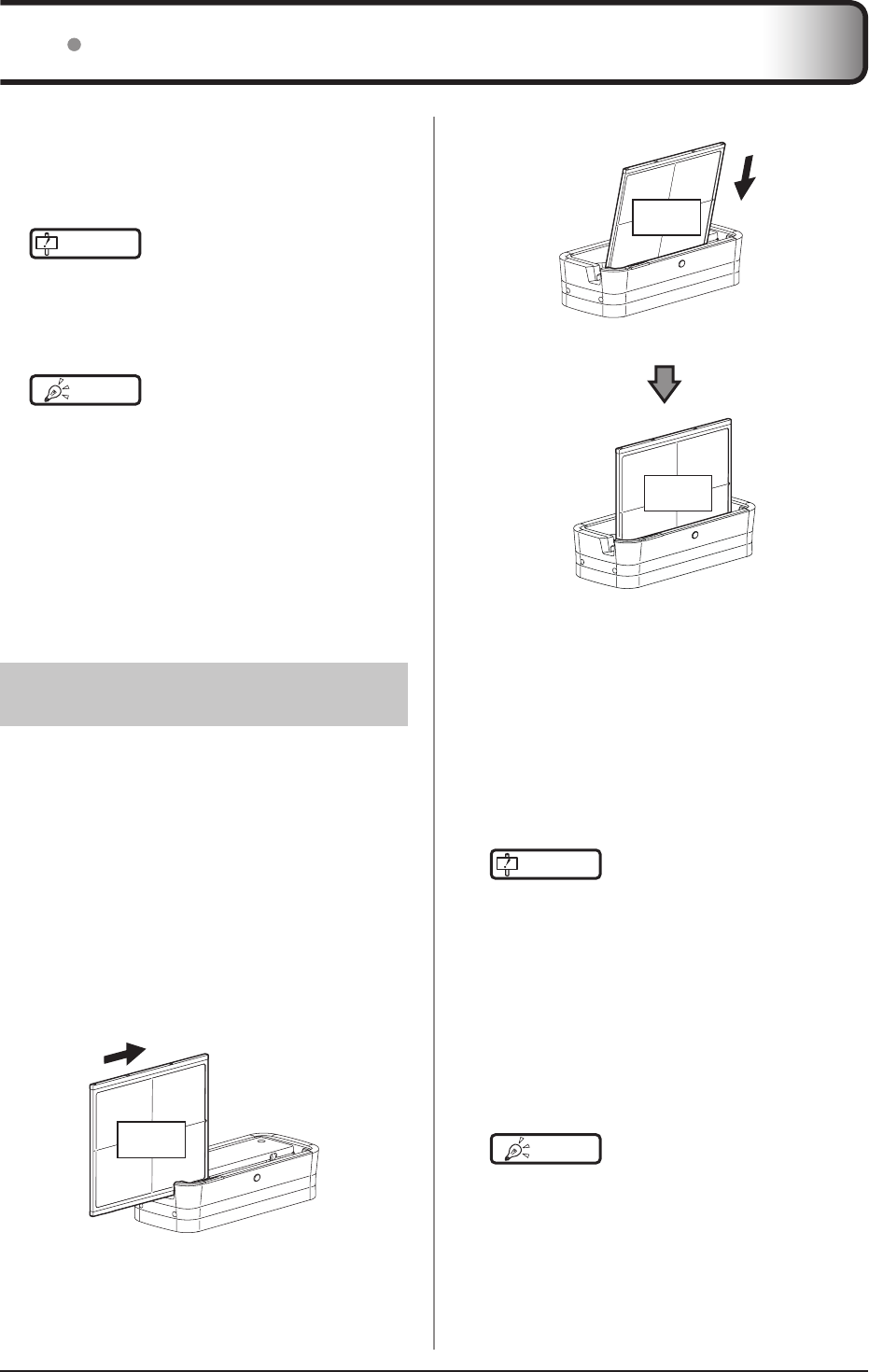
Exposure with the Aero Sync mode
• TouseagridinAeroSyncmode,aligntheorien-
tationofthetriangularmarkoftheAeroDRDe-
tectorwiththegridbarasshowninthefollowing
gure.
AeroDRDetectorGrid
Gridbar
Triangularmark
• Donotuseadditionalltersforexposuredosere-
duction.
56
ChargetheAeroDRDetectorwhentheLED(blue)on
theAeroDRDetectorlightsorashes,orwhenthebat-
terylevelgetslowinthestatusdisplayoftheAeroDR
Detectorontheimageprocessingcontroller.
IMPORTANT
•••••••••••••••••••••••••••••••••••••
• Duringcharging,iftheAeroDRDetectorshouldbe-
comehot,stopchargingimmediately.
• Ifchargingerrorsoccurrepeatedly,contactKonicaMi-
noltatechnicalrepresentatives.
•••••••••••••••••••••••••••••••••••••••••••••••••••••
HINT •••••••••••••••••••••••••••••••••••••
• TheAeroDRDetectorcanbechargedwhenthepower
iseitheronoroff.
• TheAeroDRDetectorcan be used while stopping
charginginprogress.
• TochargetheAeroDRDetectorwiththeAeroDRBat-
teryChargerwhenyoudonotuseitforalongtime
suchasduringthenight,chargetheAeroDRDetector
withitspowerturnedoff.
• Evenifyouusethebatteryequippedwiththisdevice
forrepeatedquickcharginganduse,deteriorationof
batterylifeissmallcomparedtoalithium-ionbattery.
•••••••••••••••••••••••••••••••••••••••••••••••••••••
331 Charging with AeroDR
Battery Charger
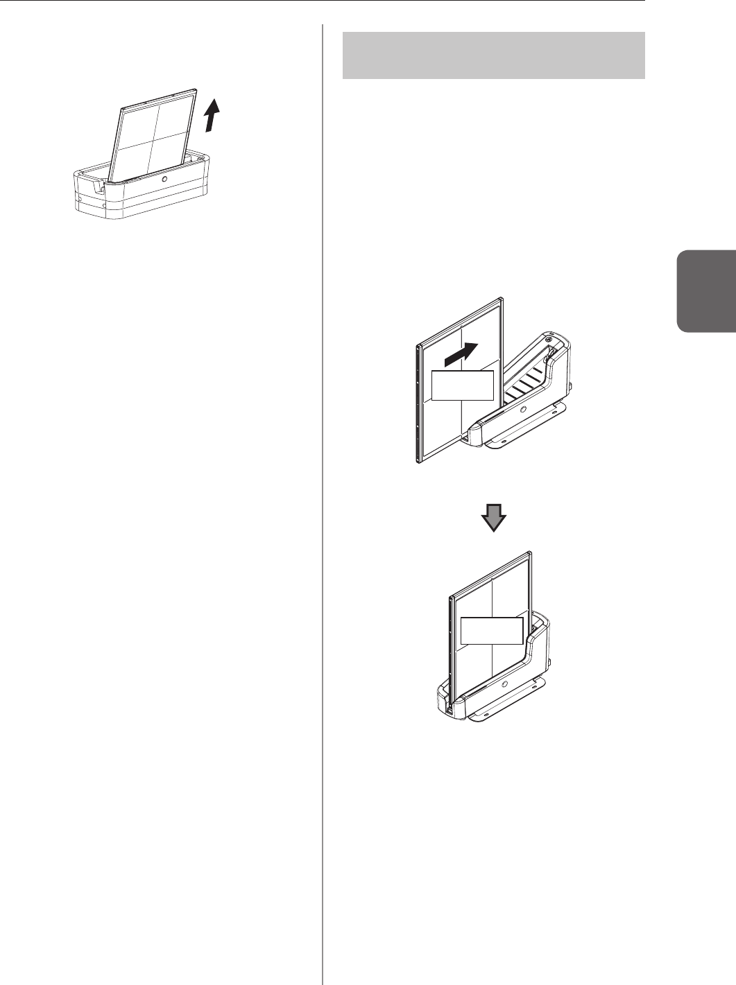
InsertingtheAeroDRDetectorintotheAeroDRBattery
ChargerperformschargingoftheAeroDRDetector.
1 Conrm that the LED (green) of the Aero-
DR Battery Charger is slowly ashing
2 Slowly
insert the AeroDR Detector with its ex-
posure side pointed toward the operator until
the buzzer sounds When inserted, charging
of the AeroDR Detector begins
Insert from the side
Exposure
side
Slide slowly
Insert from the front (top)
Exposure
side
Load slowly
Exposure
side
Inserted
3 Once the AeroDR Detector is inserted cor-
rectly and charging starts, the LED (blue)
on the AeroDR Battery Charger will light
4 Once charging of the AeroDR Detector is
completed, the LED (blue) on the AeroDR
Battery Charger will turn off
IMPORTANT
•••••••••••••••••••••••••••••••••••••
• HandletheAeroDRDetectorwithextremecarewhen
insertingitintotheAeroDRBatteryCharger.
• TheLEDoftheAeroDRDetectorisnotvisiblewhen
theAeroDRDetectorisinsertedintotheAeroDRBat-
teryCharger.
• ThewiredconnectionconnectoroftheAeroDRDe-
tectormaybecomewarmrightafterchargingonthe
AeroDRBatteryCharger.Thisoftenoccursduring
chargingandisnotamalfunction.
• TheAeroDR1012HQcannotbechargedintheAero-
DRBatteryCharger.
•••••••••••••••••••••••••••••••••••••••••••••••••••••
HINT •••••••••••••••••••••••••••••••••••••
• Ifthereisanyproblemduringcharging,theLED(or-
ange)ontheAeroDRBatteryChargerwilllight.Also,
chargingwillstopwhenanerroroccurs.
•••••••••••••••••••••••••••••••••••••••••••••••••••••
33 Charging of AeroDR Detector
3.3ChargingofAeroDRDetector
57
Chapter 3
5 Remove the AeroDR Detector from the
AeroDR Battery Charger
• PulltheAeroDRDetectortoremoveit.
332 Charging with AeroDR
Battery Charger2
InsertingtheAeroDRDetectorintotheAeroDRBattery
Charger2performschargingoftheAeroDRDetector.
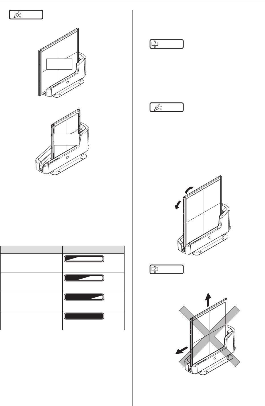
1 Conrm that the LED (green) of the Aero-
DR Battery Charger2 is slowly ashing
2 Slowly insert the AeroDR Detector with
its exposure side pointed toward the op-
erator until the buzzer sounds When in-
serted, charging of the AeroDR Detector
begins
Exposure
side
Load slowly
Exposure
side
Inserted
3.3ChargingofAeroDRDetector
58
HINT •••••••••••••••••••••••••••••••••••••
• AeroDR1717HQisinserted
Exposure
side
• AeroDR1012HQisinserted
Exposure
side
•••••••••••••••••••••••••••••••••••••••••••••••••••••
3 Once the AeroDR Detector is inserted cor-
rectly and charging starts, the LED (blue)
on the AeroDR Battery Charger2 will ash
or light
• TheLED(blue)ontheAeroDRBatteryCharger2
changesaccordingtothelevelofbatterypower
oftheAeroDRDetector.
Battery level LED display
2%orless
Slowashing(blue)
3to49%
LitandSlowashing(blue)
50to79%
LitandSlowashing(blue)
80%ormore
Lit(blue)
4 Once charging of the AeroDR Detector
is completed, all the LEDs (blue) on the
AeroDR Battery Charger2 will turn on
IMPORTANT
•••••••••••••••••••••••••••••••••••••
• HandletheAeroDRDetectorwithextremecarewhen
insertingitintotheAeroDRBatteryCharger2.
• ThewiredconnectionconnectoroftheAeroDRDe-
tectormaybecomewarmrightafterchargingonthe
AeroDRBatteryCharger2.Thisoftenoccursduring
chargingandisnotamalfunction.
•••••••••••••••••••••••••••••••••••••••••••••••••••••
HINT •••••••••••••••••••••••••••••••••••••
• Ifthereisanyproblemduringcharging,theLED(or-
ange)ontheAeroDRBatteryCharger2willlight.Also,
chargingwillstopwhenanerroroccurs.
•••••••••••••••••••••••••••••••••••••••••••••••••••••
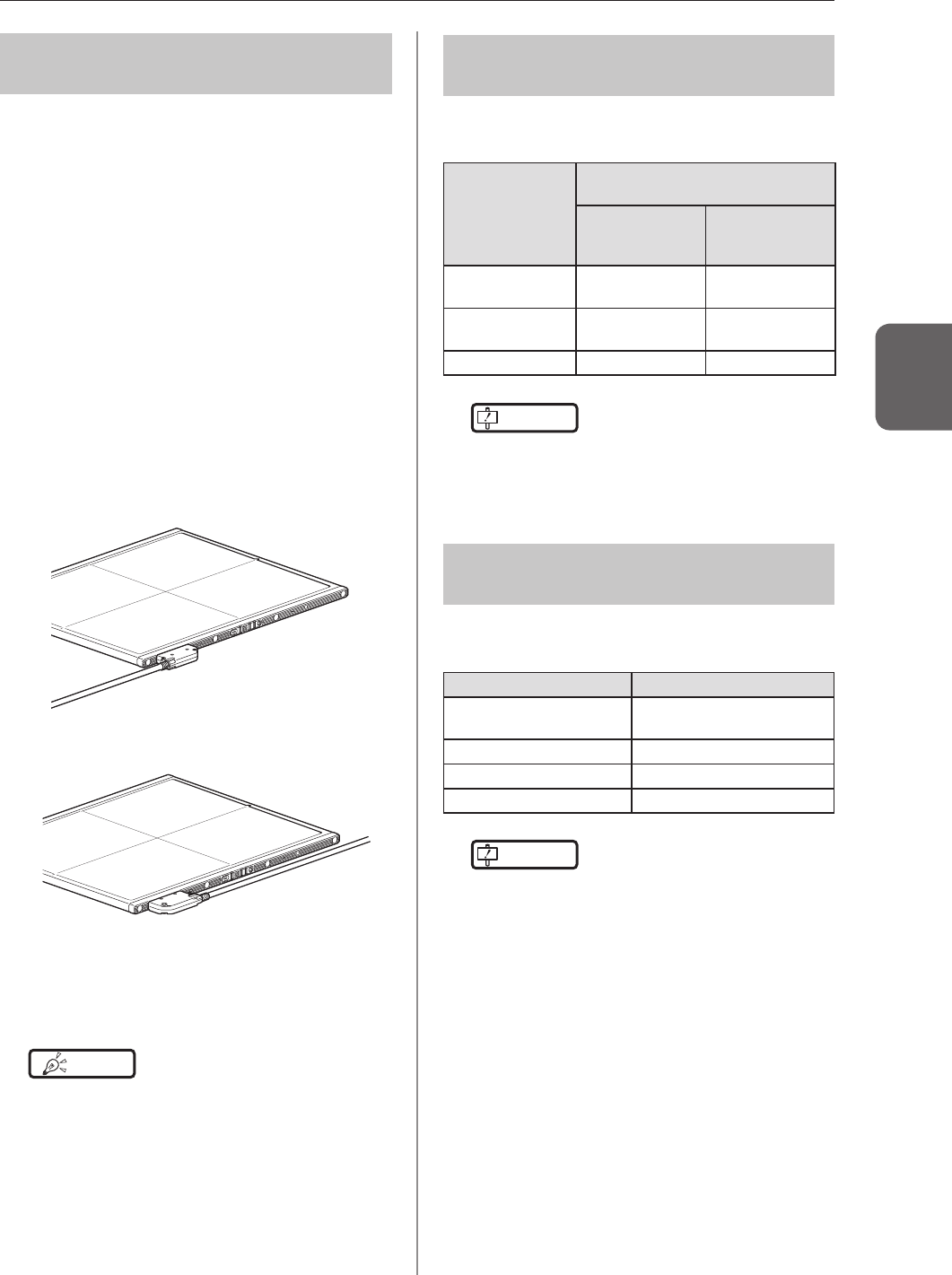
5 Remove the AeroDR Detector from the
AeroDR Battery Charger2
• TilttheAeroDRDetectorinthedirectionshown
inthefollowinggureandremoveit.
IMPORTANT
•••••••••••••••••••••••••••••••••••••
• AstheAeroDRDetectorislockedbyamagnet,donot
pullitouthorizontallyorvertically.
•••••••••••••••••••••••••••••••••••••••••••••••••••••
3.3ChargingofAeroDRDetector
59
Chapter 3
333 Charging with the wired
cable
ConnectingtheAeroDRUFCableorAeroDRI/FCable
totheAeroDRDetectorperformschargingoftheAero-
DRDetector.
1 Conrm that the LED (green) of the Aero-
DR Interface Unit or the Detector Connec-
tion LED (green) and Generator Interface
LED (green) of the AeroDR Interface Unit2
light
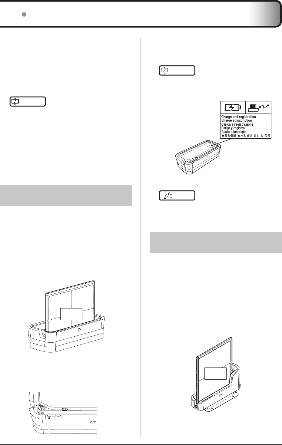
2 Securely connect the AeroDR I/F Cable or
AeroDR UF Cable to the wired connection
connector on the AeroDR Detector Once
it is connected, the AeroDR Detector will
start charging
When the AeroDR I/F Cable is connected
When the AeroDR UF Cable is connected
3 Once the charging of the AeroDR Detector
is higher than 10%, the LED (blue) on the
AeroDR Detector will go out
HINT •••••••••••••••••••••••••••••••••••••
• Conrmcompletionoffullchargeandthelevelofbat-
terypowerwiththeimageprocessingcontroller.
• Ifthereisanyproblemduringcharging,theLED(or-
ange)ontheAeroDRDetectorwilllight.Also,charging
willstopwhenanerroroccurs.
•••••••••••••••••••••••••••••••••••••••••••••••••••••
334 Charging time guide
TofullychargetheAeroDRDetectorrequiresthefol-
lowingchargingtime.
Chargingstatus
ChargingtimeoftheAeroDRDetector
whenthepowerisoff
AeroDR1417HQ
AeroDR1417S
AeroDR1717HQ
AeroDR1012HQ
ViatheAeroDR
BatteryCharger Approx.30min -
ViaAeroDRBat-
teryCharger2 Approx.60min Approx.30min
Viawiredcable Approx.60min Approx.30min
IMPORTANT
•••••••••••••••••••••••••••••••••••••
• WhentheAeroDRDetectorison,thechargingtime
willbeslightlylongerasitdependsontheoperation
status.
•••••••••••••••••••••••••••••••••••••••••••••••••••••
335 AeroDR Detector charg-
ing display
TheAeroDRDetectorLED(blue)changesaccording
tothelevelofbatterypower.
Batterylevel LEDdisplay
Lessthan3%(exposurenot
possible) Lit(blue)
Lessthan5% Fastashing(blue)
Lessthan10% Slowashing(blue)
10%ormore Off
IMPORTANT
•••••••••••••••••••••••••••••••••••••
• Whenthebatteryrunsdowncompletely,alltheLEDs
goout.ConfirmthattheLED(green)eitherlightsor
asheswhenyouperformexposure.
•••••••••••••••••••••••••••••••••••••••••••••••••••••
60
ByregisteringtheAeroDRDetectorintheimageprocess-
ingcontrollerusingoneofthefollowingmethods,theAero-
DRDetectorcanbemovedbetweenexposurerooms.
• InsertitintotheAeroDRBatteryCharger/AeroDR
BatteryCharger2
• ConnecttheAeroDRI/FCableorAeroDRUFCable
tothewiredconnectionconnector
IMPORTANT
•••••••••••••••••••••••••••••••••••••
• AeroDR1012HQcannotberegisteredwiththeAero-
DRBatteryCharger.
• WhenusingImagePilotastheimageprocessingcon-
troller,itisnotpossibletomovetheAeroDRDetector
betweendifferentexposurerooms.
• Onceitisregisteredinanewexposureroom,itwill
notbeusableinthepreviousexposureroom.When
returningtoapreviousexposureroom,performthe
registrationoperationagain.
•••••••••••••••••••••••••••••••••••••••••••••••••••••
341 Registration with AeroDR
Battery Charger
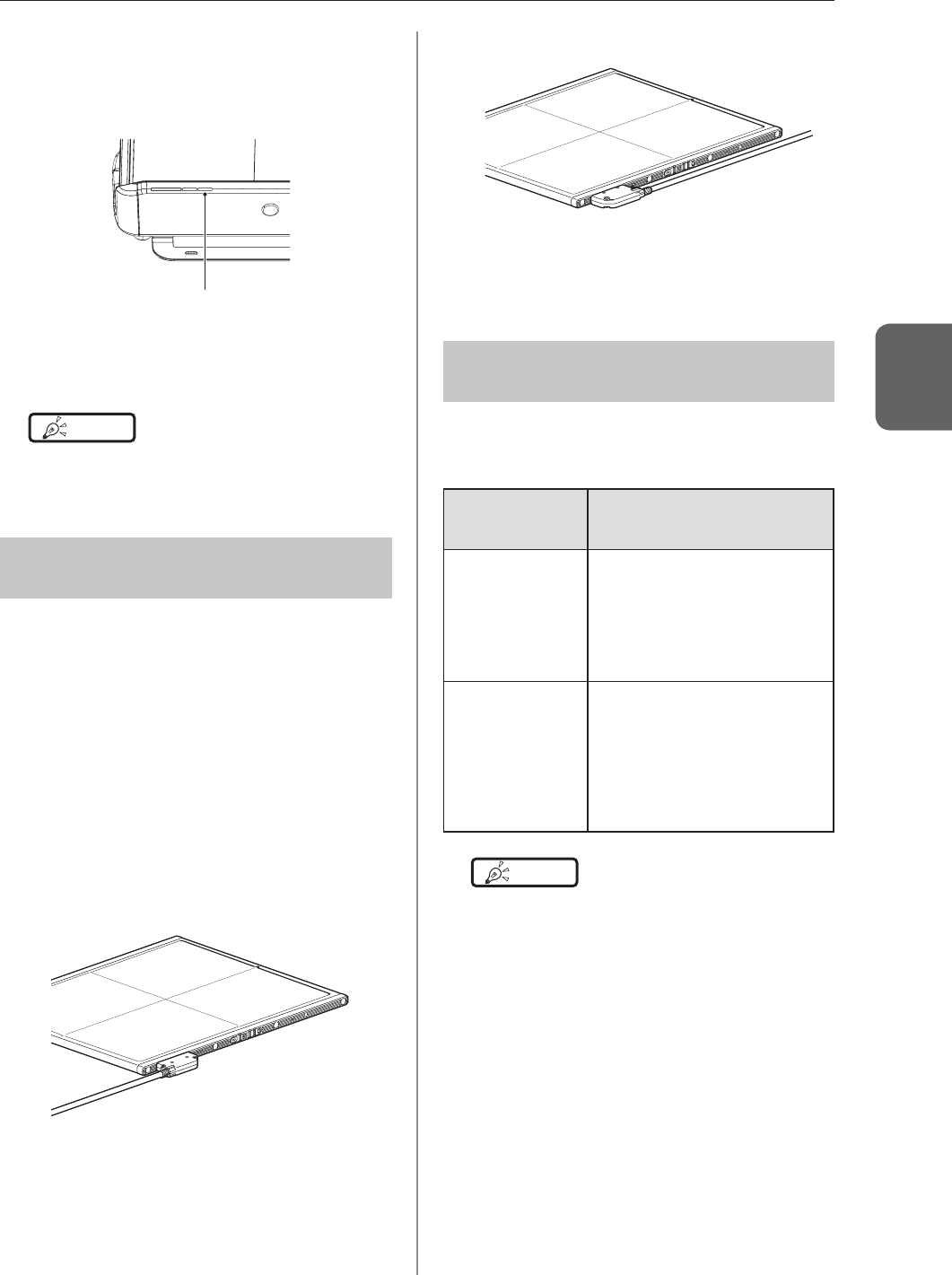
ToregistertheAeroDRDetectorintheAeroDRBattery
Charger,followtheprocedurebelow.
1 Make sure that all the devices in the destina-
tion exposure room are usable
2
Insert the AeroDR Detector into AeroDR Bat-
tery Charger in the destination exposure room
• Registrationprocesswillstart.
Exposure
side
3 Once the registration is completed, a
buzzer will sound on the AeroDR Battery
Charger, and the LED (green) will change
from slow ashing to lit
LED(green)
34 Registration and selection of the AeroDR Detector
4 Conrm that the AeroDR Detector icon is
displayed on the image processing con-
troller
IMPORTANT
•••••••••••••••••••••••••••••••••••••
• When anAeroDRBatteryChargerexclusively for
chargeisused,conrmthatthebatterychargerinthe
destinationhasa"Chargeandregistration"label.
•••••••••••••••••••••••••••••••••••••••••••••••••••••
HINT •••••••••••••••••••••••••••••••••••••
• Charging willalsostartwhentheAeroDR Detector
isinsertedintotheAeroDRBatteryCharger,andthe
AeroDRBatteryChargerLED(blue)willlight.
•••••••••••••••••••••••••••••••••••••••••••••••••••••
342 Registration with AeroDR
Battery Charger2
ToregistertheAeroDRDetectorintheAeroDRBattery
Charger2,followtheprocedurebelow.
1
Make sure that all the devices in the destina-
tion exposure room are usable
2 Insert the AeroDR Detector into AeroDR
Battery Charger2 in the destination expo-
sure room
• Registrationprocesswillstart.
Exposure
side
3.4RegistrationandselectionoftheAeroDRDetector
61
Chapter 3
3 Once the registration is completed, a
buzzer will sound on the AeroDR Battery
Charger2, and the LED (green) will change
from slow ashing to lit
LED(green)
4
Confirm that the AeroDR Detector icon is
displayed on the image processing control-
ler
HINT •••••••••••••••••••••••••••••••••••••
• Charging willalsostartwhentheAeroDR Detector
isinsertedintotheAeroDRBatteryCharger,andthe
AeroDRBatteryChargerLED(blue)willlightorash.
•••••••••••••••••••••••••••••••••••••••••••••••••••••
343 Registration with the
wired cable
To registertheAeroDRDetector by connectingthe
AeroDRI/FCableorAeroDRUFCabletothewired
connectionconnector,followtheproceduresbelow.
1 Make sure that all the devices in the desti-
nation exposure room are usable
2 Securely connect the AeroDR I/F Cable or
AeroDR UF Cable to the wired connection
connector on the AeroDR Detector
• Registrationprocesswillstart.
When the AeroDR I/F Cable is connected
When the AeroDR UF Cable is connected
3 Conrm that the AeroDR Detector icon is
displayed on the image processing con-
troller
344 Selection of the AeroDR
Detector
AnAeroDRDetectorisselectedasfollowsdepending
onthenumberregisteredoneachimageprocessing
controller.
Number of reg-
istered AeroDR
Detectors
Selection method
1
•AeroDRDetectorisselected
automaticallywhenthatAeroDR
Detectorisreadytobeselected.
•TheAeroDRDetectorisnotse-
lectedifitisnotsetinawallstand
ortablethatmatchestheorder
information.
Multiple
•TheAeroDRDetectorthatwas
selectedimmediatelybeforehand
willbeselectedautomaticallyifitis
readytobeselected.
•IfthereisnoAeroDRDetectorin
thewallstandortablethatmatches
theorderinformation,noAeroDR
Detectorwillbeselected.
HINT •••••••••••••••••••••••••••••••••••••
• TheLED(green)oftheselectedAeroDRDetectorislit.
•••••••••••••••••••••••••••••••••••••••••••••••••••••
3.4RegistrationandselectionoftheAeroDRDetector
62
345 Manual selection of the
AeroDR Detector
SelectingtheAeroDRDetectormanuallyisperformed
withthefollowingprocedure.
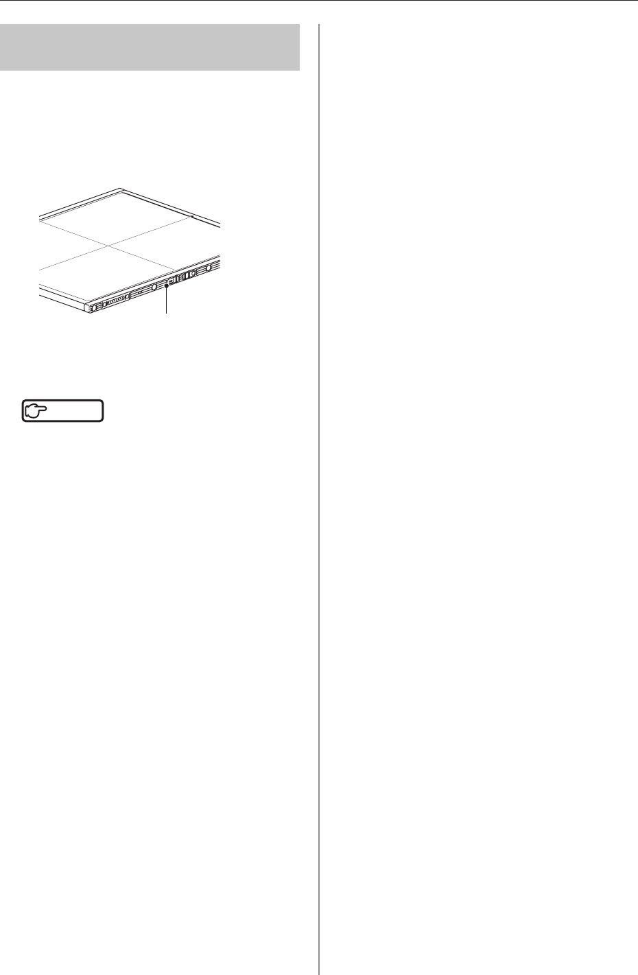
1 Press the selection switch of the AeroDR
Detector that will be used for 2 seconds or
longer
Selectionswitch
2 After selection is completed, the LED
(green) of the AeroDR Detector is lit
Reference
•••••••••••••••••••••••••••••••••••••
• TheAeroDRDetectorcanalsobeselectedmanually
fromtheimageprocessingcontroller.Fordetails,refer
tothe"OperationManual"oftheimageprocessing
controller.
•••••••••••••••••••••••••••••••••••••••••••••••••••••
63
Chapter 3
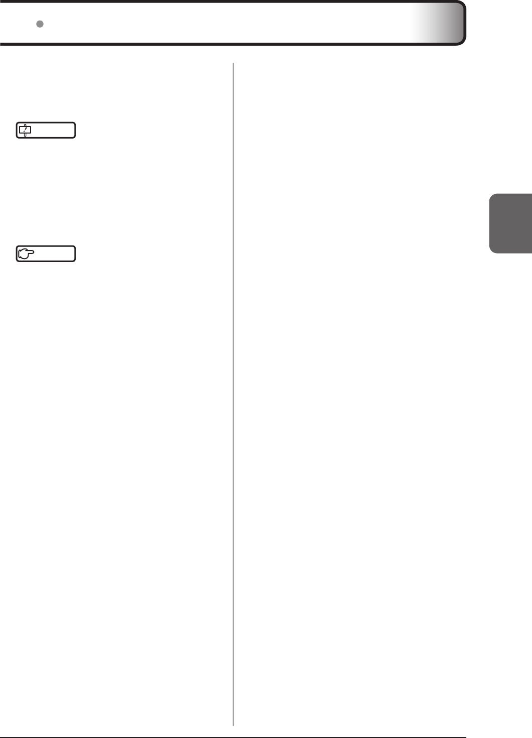
35 Calibration
InorderfortheAeroDRDetectortoprovideoptimalim-
ages,performthecalibrationeverythreemonths.
Thecalibrationisperformedwiththeimageprocessing
controller.
IMPORTANT
•••••••••••••••••••••••••••••••••••••
• Itisnecessarytoperformthegaincalibrationperiodi-
callytocompensateforchangesovertimeorchanges
intheexposureenvironment.
• FullychargetheAeroDRDetectorbeforethecalibra-
tion.
• Performbywaitingatleast10minutesaftertheprevi-
ousexposure.
•••••••••••••••••••••••••••••••••••••••••••••••••••••
Reference
•••••••••••••••••••••••••••••••••••••
• Forthecalibration,refertothe"UserToolOperation
Manual"orthe"OperationManual"oftheimagepro-
cessingcontroller.
•••••••••••••••••••••••••••••••••••••••••••••••••••••
64
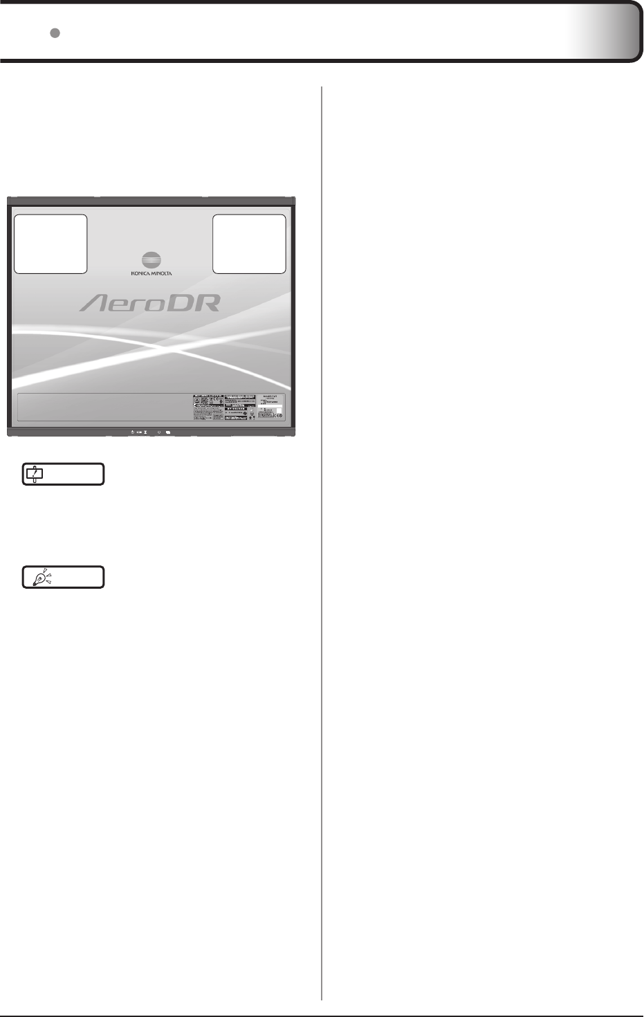
36 Position to afx AeroDR Detector identication label
Whenusingmorethan1AeroDRDetectorandafx-
ingidenticationlabels(stickers)totheoutsideofthe
AeroDRDetectors,itisrecommendedtoafxthela-
belstothe2places((1),(2))shownasfollows.
Position to afx AeroDR Detector identication label
Positiontoafx
AeroDRDetector
identicationlabel
(recommended)
(1)
Positiontoafx
AeroDRDetector
identicationlabel
(recommended)
(2)
IMPORTANT
•••••••••••••••••••••••••••••••••••••
•
Afxthelabelsonlyintherecommendedplaces.Fail-
uretodosomaycausethelabelstocomeofforimage
unevennesstooccur.
••••••••••••••••••••••••••••••••••••••••••••••••••••
HINT •••••••••••••••••••••••••••••••••••••
• Useofcommerciallyavailablevinyl(Tepra,etc.)
labelsarerecommendedfortheidentificationlabels
(stickers).Whenpossible,uselabelsthatdonoteasily
peeloff.
• Itisrecommendedtowritethenameandidentication
numberregisteredintheimageprocessingcontroller
onthelabel.
••••••••••••••••••••••••••••••••••••••••••••••••••••

65
Chapter 4
Status (LED) Display
ThischapterdescribestheLEDdisplaypatternsandthestatus
oftherespectivedevices.
66
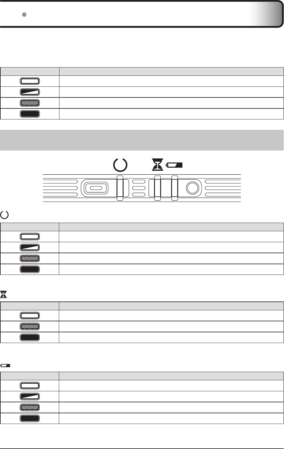
StatusoftherespectivedevicescanbeconrmedwithLEDs.
Checkthestatusoftherespectivedevices,referringtothe"LEDdisplaypattern".
LED display pattern
Notation Display pattern
Off
Slowashing
Fastashing
On
411 AeroDR Detector
: Status LED (green)
Display pattern Status
Shutdowncondition
Standingby
AeroDRDetectorbeingselected
Exposing
*Duringstartup/shutdownprocessing,italsoashesfastandislit.
: Busy/error LED (orange)
Display pattern Status
Shutdownconditionorstandingby
Exposingorperformingmaintenance
Erroroccurred
*Duringstartup/shutdownprocessing,italsoashesfastandislit.
: Battery LED (blue)
Display pattern Status
Shutdownconditionorbatterylevelis10%orabove
Batterylevelislessthan10%
Batterylevelislessthan5%
Batterylevelislessthan3%
*Duringstartup/shutdownprocessing,italsoashesfastandislit.
41 LED display of respective devices
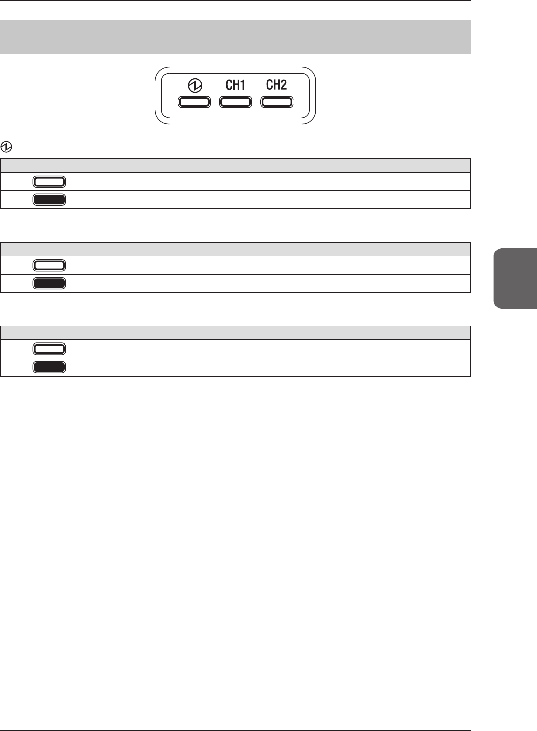
4.1
LEDdisplayofrespectivedevices
67
Chapter 4
412 AeroDR Interface Unit
: Power LED (green)
Display pattern Status
Shutdowncondition
Operating
CH1: Feeding1 LED (blue)
Display pattern Status
Shutdownconditionorfeeding1isnotconnectedtotheAeroDRDetector
TheAeroDRDetectorisconnectedtofeeding1
CH2: Feeding2 LED (blue)
Display pattern Status
Shutdownconditionorfeeding2isnotconnectedtotheAeroDRDetector
TheAeroDRDetectorisconnectedtofeeding2
4.1
LEDdisplayofrespectivedevices
68
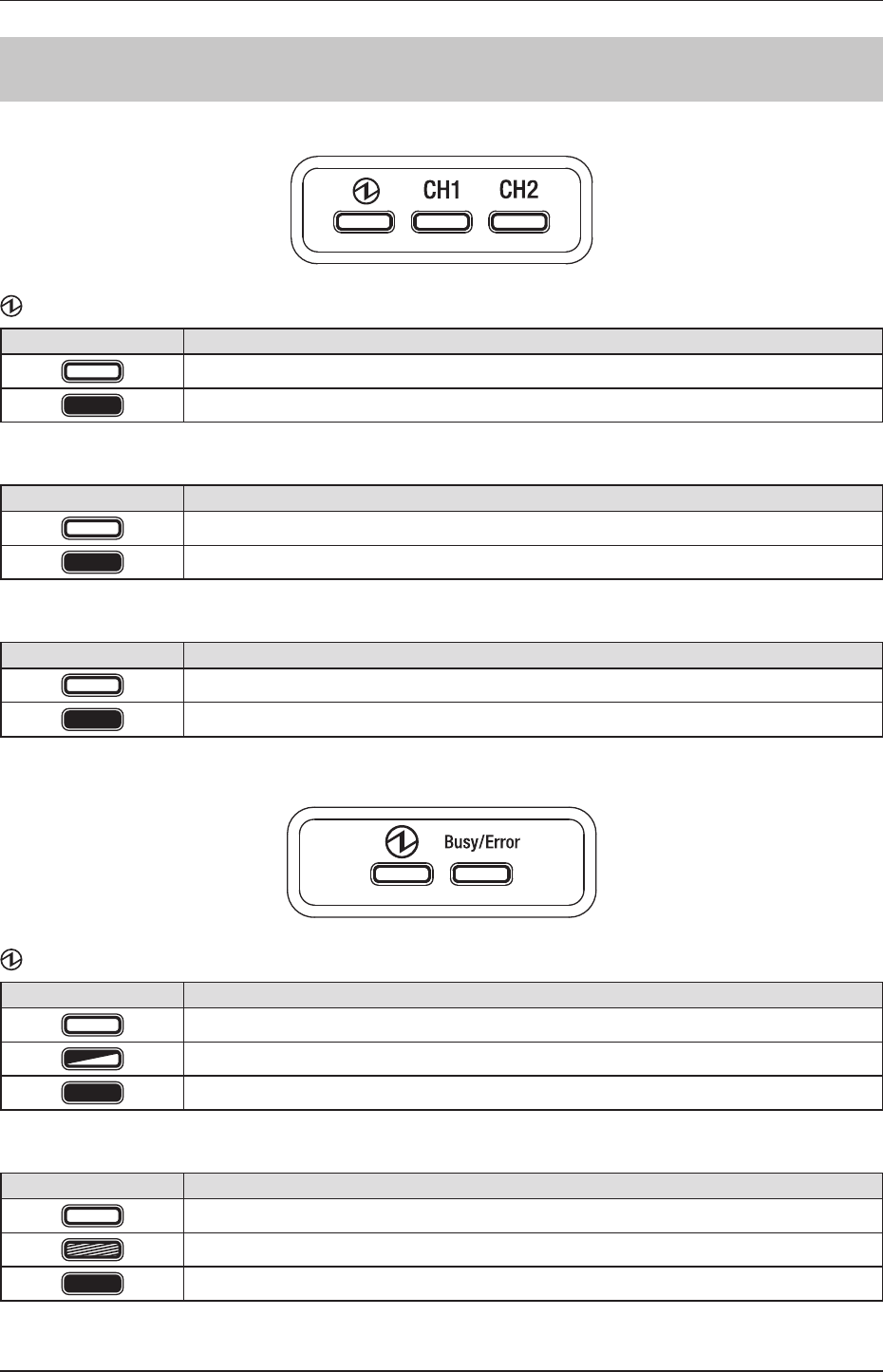
413 AeroDR Interface Unit2
Detector Connection LED
: Power LED (green)
Display pattern Status
Shutdowncondition
Operating
CH1: Feeding1 LED (blue)
Display pattern Status
Shutdownconditionorfeeding1isnotconnectedtotheAeroDRDetector
TheAeroDRDetectorisconnectedtofeeding1
CH2: Feeding2 LED (blue)
Display pattern Status
Shutdownconditionorfeeding2isnotconnectedtotheAeroDRDetector
TheAeroDRDetectorisconnectedtofeeding2
Generator Interface LED
: Power LED (green)
Display pattern Status
Shutdowncondition
Operatingandnotconnectedtotheimageprocessingcontroller
Operatingandconnectedtotheimageprocessingcontroller
Busy/Error : Busy/error LED (orange)
Display pattern Status
Shutdownconditionorstandingby
Exposingorperformingmaintenance
Erroroccurred
4.1
LEDdisplayofrespectivedevices
69
Chapter 4
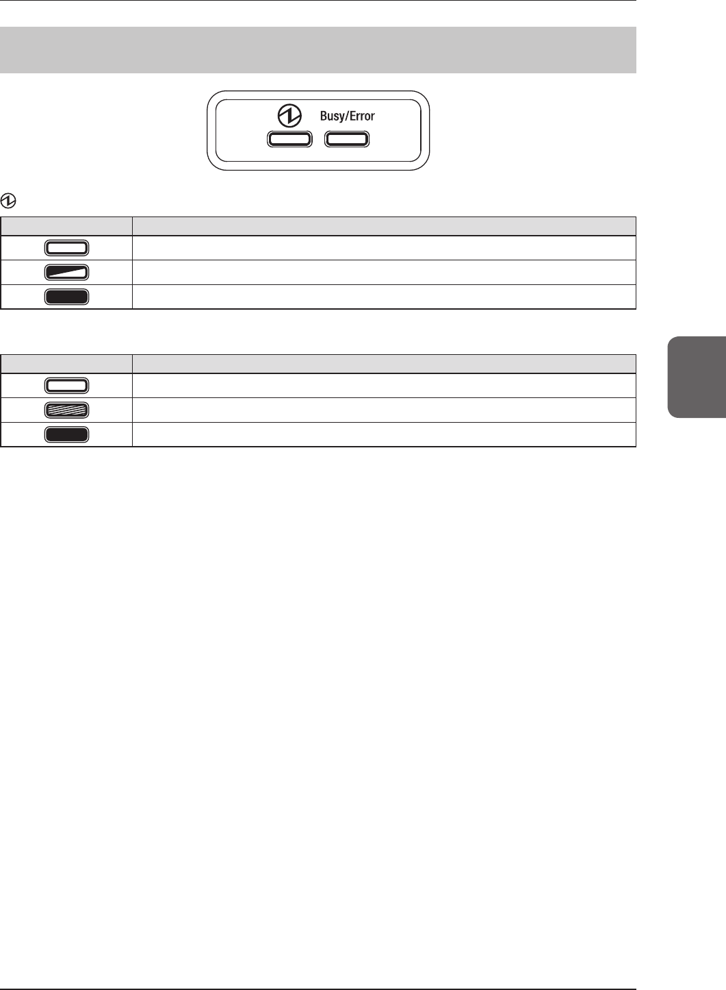
414 AeroDR Generator Interface Unit
: Power LED (green)
Display pattern Status
Shutdowncondition
Operatingandnotconnectedtotheimageprocessingcontroller
Operatingandconnectedtotheimageprocessingcontroller
Busy/Error : Busy/error LED (orange)
Display pattern Status
Shutdownconditionorstandingby
Exposingorperformingmaintenance
Erroroccurred
4.1
LEDdisplayofrespectivedevices
70
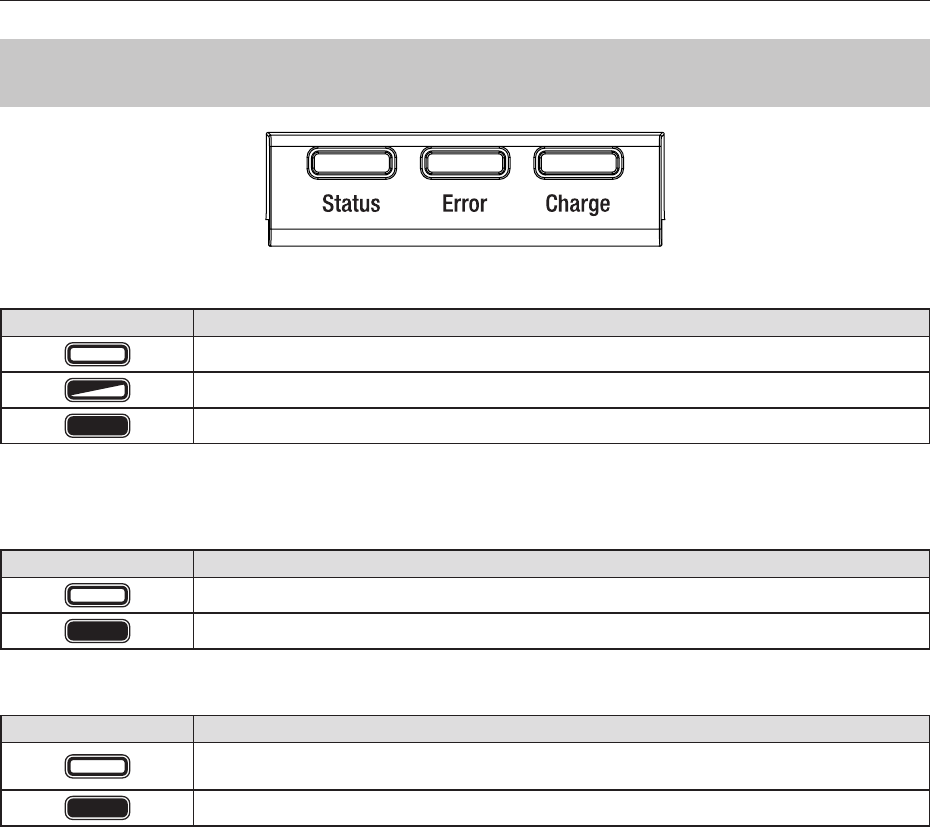
415 AeroDR Battery Charger
Status: Status LED (green)
Display pattern Status
Shutdowncondition
Operating
RegistrationprocessingoftheinsertedAeroDRDetectoriscomplete
* BecausethechargerdedicatedforchargingdoesnotperformregistrationprocessingoftheAeroDRDetector,thestatusLEDal-
waysashesslowly.
Error : Error LED (orange)
Display pattern Status
Shutdownconditionoroperatingnormally
Erroroccurred
Charge: Feeding LED (blue)
Display pattern Status
ShutdownconditionorstandingbyforinsertionoftheAeroDRDetector
BatterychargedduringAeroDRDetectorinsertion
AeroDRDetectorbatterycharging
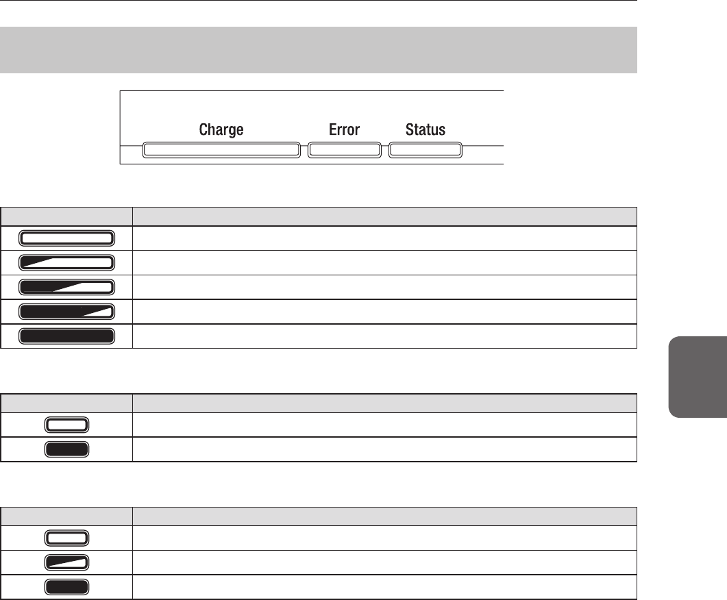
4.1
LEDdisplayofrespectivedevices
71
Chapter 4
416 AeroDR Battery Charger2
Charge: Feeding LED (blue)
Display pattern Status
ShutdownconditionorstandingbyforinsertionoftheAeroDRDetector
AeroDRDetectorbatterycharging(batterylevelislessthan2%)
AeroDRDetectorbatterycharging(batterylevelis3to49%)
AeroDRDetectorbatterycharging(batterylevelis50to79%)
AeroDRDetectorbatterycharging(batterylevelishigherthan80%)
Error : Error LED (orange)
Display pattern Status
Shutdownconditionoroperatingnormally
Erroroccurred
Status: Status LED (green)
Display pattern Status
Shutdowncondition
Operating
RegistrationprocessingoftheinsertedAeroDRDetectoriscomplete
* BecausethechargerdedicatedforchargingdoesnotperformregistrationprocessingoftheAeroDRDetector,thestatusLEDal-
waysashesslowly.
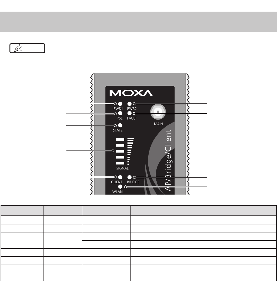
4.1
LEDdisplayofrespectivedevices
72
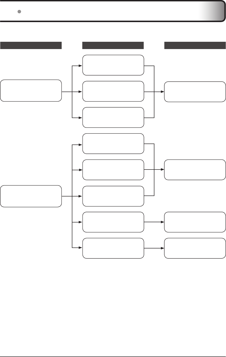
417 Access Point
HINT •••••••••••••••••••••••••••••••••••••••••••••••••••••••••••••••••••••••••••••••••••••••••••••••••••••
• Theillustrationsandexplanationmerelyshowsanexample.
•••••••••••••••••••••••••••••••••••••••••••••••••••••••••••••••••••••••••••••••••••••••••••••••••••••••••••••••••••••
Cannotbeused
withthisdevice
Cannotbeused
withthisdevice
PoE(umber)
STATE
(green/red)
CLIENT(green)
FAULT(red)
WLAN(umber)
BRIDGE(green)
SIGNAL(green)
LED Lighting color Lighting pattern Status
PoE Umber On Powerisbeingsupplied.
FAULT Red Flashing Errorisoccurring.
STATE Green/
Red
Green/on Lightswhenoperationpreparationiscompleted.
Red/on Errorisoccurring.
SIGNAL Green On Signalstrengthofwireless.(Onlyinclientmode)
BRIDGE Green On Operatinginbridgemode.
CLIENT Green On Operatinginclientmode.
WLAN Umber On OperatinginwirelessLANmode.(Normal)

73
Chapter 5
Troubleshooting
Thischapterdescribesproblemsthatmayoccuranderrorcodesthatmaybe
displayed,andhowtoresolveeachofthem.
74
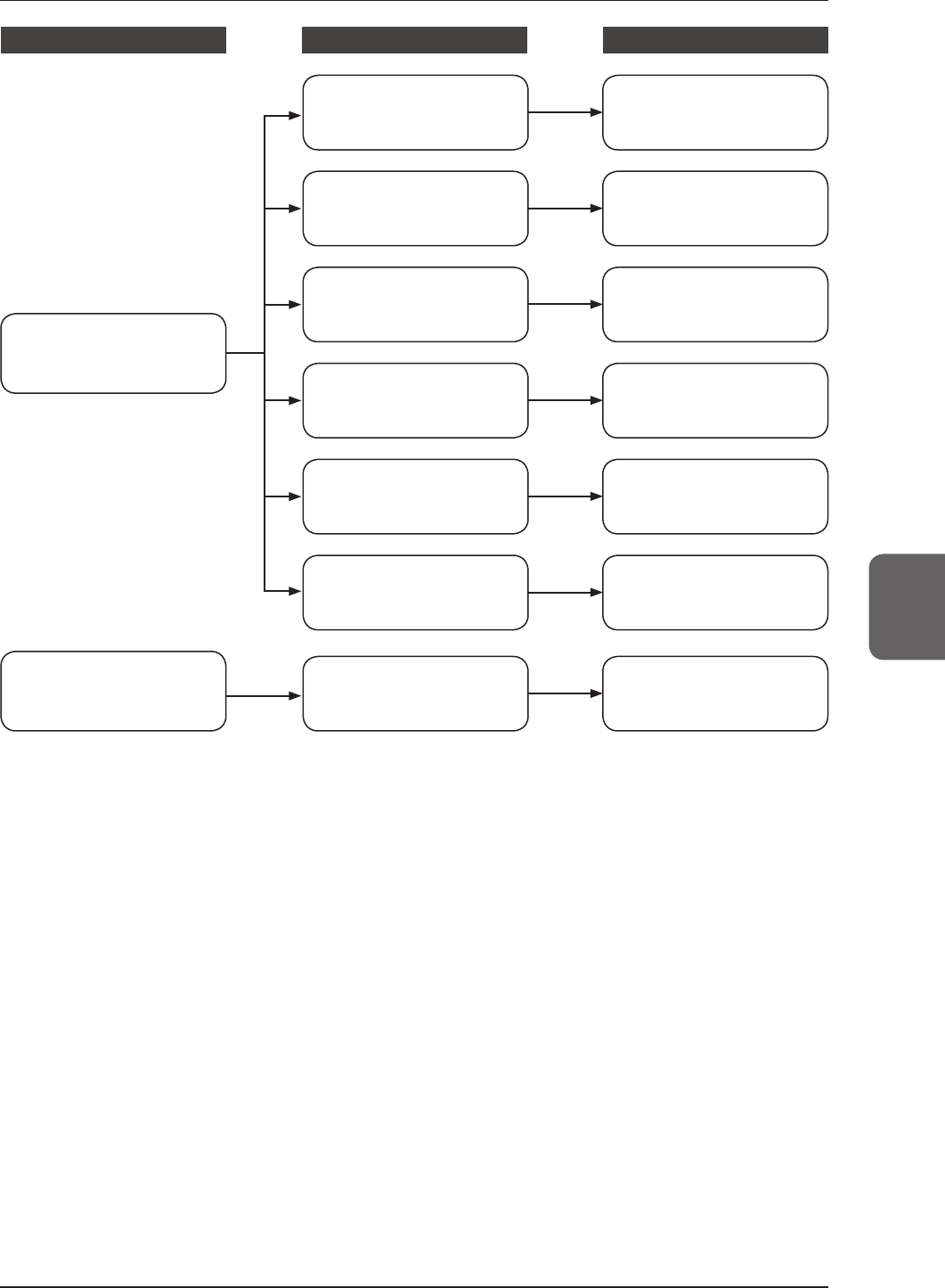
51 Support ow during trouble
Ifthefollowingproblemsoccurwithanyofthesedevices,consulttherespectivereferencesforcountermeasures.
Status Device
Reference for countermeasures
AeroDRDetector
AeroDRGeneratorInterfaceUnit
Consultthe"OperationManual"
oftheimageprocessingcontrol-
lertotakethecountermeasures.
Errorcodeisdisplayed.
AeroDRBatteryCharger2
Consult"5.2.5AeroDRBattery
Charger2"totakethecounter-
measures.
AeroDRInterfaceUnit2
AeroDRDetector
AeroDRGeneratorInterfaceUnit
Confrmtheerrorcodedisplayed
ontheimageprocessingcontrol-
ler,andperformcorrectiveactions.
AeroDRBatteryCharger
Consult"5.2.4AeroDRBattery
Charger"totakethecounter-
measures.
ErrorLEDlights.
AeroDRInterfaceUnit2
5.1Supportowduringtrouble
75
Chapter 5
Status Device
Reference for countermeasures
AeroDRDetector
Consult"5.2.1AeroDRDetec-
tor"totakethecountermea-
sures.
AeroDRInterfaceUnit
Consult"5.2.2AeroDRInter-
faceUnit"totakethecounter-
measures.
AeroDRBatteryCharger2
Consult"5.2.5AeroDRBattery
Charger2"totakethecounter-
measures.
AeroDRBatteryCharger
Consult"5.2.4AeroDRBattery
Charger"totakethecounter-
measures.
AccessPoint Consult"5.2.6AccessPoint"to
takethecountermeasures.
Troublehasoccurredineachdevice.
(Troubleotherthanerrorcodedis-
playandaliterrorLED)
Imageprocessingcontroller
Consult"5.2.7Imageprocess-
ingcontroller/Images"totake
thecountermeasures.
Imageprocessingcontrolleror
imagerelatedtroublehasoc-
curred.
AeroDRInterfaceUnit2
Consult"5.2.3AeroDRInter-
faceUnit2"totakethecounter-
measures.

76
52 Various problems and countermeasures
Ifthefollowingproblemsoccurwithanyofthesedevices,consulttherespectivereferencesforcountermeasures.
IMPORTANT
•••••••••••••••••••••••••••••••••••••••••••••••••••••••••••••••••••••••••••••••••••••••••••••••••••••
• Afterperformingcountermeasures,iftheproblemdoesnotgoaway,contactKonicaMinoltatechnicalrepresentatives.
•••••••••••••••••••••••••••••••••••••••••••••••••••••••••••••••••••••••••••••••••••••••••••••••••••••••••••••••••••••
HINT •••••••••••••••••••••••••••••••••••••••••••••••••••••••••••••••••••••••••••••••••••••••••••••••••••••
• Whenanerrormessagehasbeendisplayedintheimageprocessingcontroller,checktheerrordescriptionandcountermea-
sureslistedinthe"OperationManual"oftheimageprocessingcontroller.
•••••••••••••••••••••••••••••••••••••••••••••••••••••••••••••••••••••••••••••••••••••••••••••••••••••••••••••••••••••
521 AeroDR Detector
Status Error description Corrective actions
TheAeroDRDetectordoesnot
startup.
Powerdoesnotgoonevenwhenthepower
switchispressedfor2secondsorlonger.
Thebatterymightbeout.Chargeitasfollows.
Then,startit.
• InsertingitintotheAeroDRBatteryCharger
formorethan2minutes
• InsertingitintotheAeroDRBatteryCharger2
formorethan6minutes
• Connectingawiredcableformorethan6
minutes
TheAeroDRDetectordoesnot
shutdown.
Powerdoesnotgooffevenwhenthepower
switchispressedfor5secondsorlonger.
Itisnotpossibletoshutdownwhileexposing.
Shutdownafterexposureisended.
ThestatusLED(green)islit,
andthebusy/errorLED(orange)
ashesrapidly.
("Ready"isnotdisplayedonthe
imageprocessingcontroller)
Systemerrorisoccurring.
Ifabusy/errorLED(orange)continuestoash
after10minuteshaselapsed,shutdownthe
AeroDRDetector.
Or,when"Ready"isnotdisplayedontheim-
ageprocessingcontroller,restartit.
WhentheAeroDRDetectoris
placedonasmoothsurface,the
AeroDRDetectorisnotstablyat-
tachedtothesmoothsurface.
AeroDRDetectoriswarped.
IftheAeroDRDetectorisstillwarpedeven
afterthedetectorisplacedonasmooth
surface,contactKonicaMinoltatechnical
representatives.
Theprotectivecoverisdeformed. ContactKonicaMinoltatechnical
representatives.
TheAeroDRDetectorwillnotgo
intothewallstandortable.
AeroDRDetectoriswarped.
IftheAeroDRDetectorisstillwarpedeven
afterthedetectorisplacedonasmooth
surface,contactKonicaMinoltatechnical
representatives.
Theprotectivecoverisdeformed. ContactKonicaMinoltatechnical
representatives.
TheAeroDRDetectorcannot
beinsertedintheAeroDR
BatteryCharger/AeroDRBattery
Charger2.
Theprotectivecoverisdeformed.
Foreignmaterialisinthewiredconnection
connectoroftheAeroDRDetector.
Referto"6.1.2Cleaning"andremovethe
foreignmaterial.
Foreignmaterialisinthebottomofthe
AeroDRBatteryCharger/AeroDRBattery
Charger2.
ContactKonicaMinoltatechnical
representatives.
TheAeroDRI/FCablecannot
beconnectedtotheAeroDR
Detector.
Partofthewiredconnectionconnectorofthe
AeroDRDetectorisdeformed.
ThespringconnectoroftheAeroDRI/FCable
isdeformed.

5.2Variousproblemsandcountermeasures
77
Chapter 5
Status Error description Corrective actions
TheAeroDRI/FCablecannot
beconnectedtotheAeroDR
Detector.
Foreignmaterialisinthewiredconnection
connectoroftheAeroDRDetector. Referto"6.1.2Cleaning"andremovethe
foreignmaterial.
Foreignmaterialisinthespringconnectoron
theAeroDRI/FCable.
Theshockwatchchangescolorto
red. PossibleexcessiveshocktoAeroDRDetector.
ContactKonicaMinoltatechnical
representatives.
Onlywiredconnectionwiththe
AeroDRDetectorcannotbeused.
Thewiredcableisnotconnectedproperly. Checkthatthewiredcableisproperlycon-
nectedtotheAeroDRDetector.
Onlywirelessconnectionwith
theAeroDRDetectorcannotbe
used.
ThereisanerrorintheAccessPoint. CheckthattheEthernetcableisproperlycon-
nectedtotheAccessPoint.
TheAeroDRDetectorandAccessPointare
beingusedunderpoorconditions.
• Wirelessdoesnotconnect
• Wirelesscommunicationterminates
• Cycletimeisextended
ChecktheinstallationlocationofAeroDR
DetectorandAccessPoint.
Whenperformanceisnoticeablylowerthanat
theinitialinstallationofthisdevice,itispos-
siblethattheinstallationenvironment/usage
environmenthavechanged.
AeroDRDetectorwiredconnec-
tionconnectorisheartedup.
AeroDRDetectorwiredconnectionconnec-
torisheatedupimmediatelyaftercharging
withAeroDRBatteryCharger/AeroDRBattery
Charger2.
Thisiscausedbychargingandisnotamal-
function.
Chargingsometimestakeslon-
ger.
Chargingtakeslongerwhenthebatteryis
overdischarged.
Ittakestimeforinternalcomponentstostart.
Becauseitisnotabnormal,waitabit.
BatteryLED(blue)ashesfast.
Usagetimewiththebatteryhasgottenshorter. Itcouldbethatthechargingfunctionofthe
batteryhasdeteriorated.Itcanbereplaced
withanewbatteryforafeeifnecessary.
Thenumberofimagesthatcanbeexposedhasdecreased.
Thechargingtimehasgottenshorter.
Noimageisacquired.* NoimageappearsafterX-rayexposure.
(1)Checkthefollowingitems.
•Didyouperformexposurein"Ready"status?
•Aretheexposureconditionscorrect?
•WasX-rayoutputlowered?
•WasX-rayvoltagesettoalowervalue?
(2)Setthesensitivitysettingoftheimage
processingcontrollerto"High"before
exposure.Ifthesettingwasalreadyat
"High",increasethevoltageoftheX-ray
andperformexposure.
Readinghasautomatically
started.*
Themachinestartsreadingtheimagewithout
X-rayexposure.
(1)Checkthefollowingitems.
•WastheAeroDRDetectorsubjectedto
strongshocksorvibrationswhile"Ready"
wasdisplayed?
•Isthesensitivitysettingoftheimagepro-
cessingcontrollercorrect?(Isthesensitivity
settingoftheimageprocessingcontroller
[High]?)
(2)Usecautiontopreventstrongshocksor
vibrationsandrestartexposure.
Exposurewasperformedina
conditionotherthanwhentheex-
posurewiththeimageprocessing
controllerwaspossible.*
Exposurewasperformedwhen"Ready"was
notdisplayedontheimageprocessingcon-
troller.Consequently,acorrectimagewasnot
acquired.
Waitforoneminuteormorebeforestarting
thenextexposure.
Exposurewasperformedwhen"Ready"was
notdisplayed.
Waitfor30secondsormorebeforestarting
thenextexposure.
* TroubleshootingintheAeroSyncmode.
IMPORTANT
•••••••••••••••••••••••••••••••••••••••••••••••••••••••••••••••••••••••••••••••••••••••••••••••••••••
• Iftheexteriororprotectivecoverisdamagedextensively,orintheeventoftheAeroDRDetectorbeingdroppedorsubjected
toshock,contactKonicaMinoltatechnicalrepresentatives.
•••••••••••••••••••••••••••••••••••••••••••••••••••••••••••••••••••••••••••••••••••••••••••••••••••••••••••••••••••••

5.2Variousproblemsandcountermeasures
78
522 AeroDR Interface Unit
Status Error description Corrective actions
PowerLED(green)doesnot
light. ACpowernotsupplied. Makesurethepowercableisconnectedcor-
rectly.
Feeding1/2LED(blue)doesnot
light.
Feeding1/2LED(blue)doesnotlighteven
whenconnectingtheAeroDRDetector.
MakesurethattheAeroDRI/FCableiscon-
nected
correctly
.
Communicationsaredown
betweendevices,andpower
LED(green)isoff.
Thepowerswitchisnoton.Or,thepower
cableisnotconnected.
MakesurethepowerswitchoftheAeroDR
InterfaceUnitison.Or,makesurethepower
cableisconnectedcorrectly.
TheAeroDRDetectorisbeing
usedwithwiredconnection,
butitisnotrecognizedonthe
imageprocessingcontroller,and
feeding1/2LEDs(blue)areoff.
TheAeroDRI/FCableisnotconnected. MakesurethattheAeroDRI/FCableis
connectedtotheAeroDRDetectorproperly.
Batteryisnotchargingwhile
theAeroDRDetectorisused
withwiredconnection(the
batterylevelonthebatterylevel
displayoftheimageprocessing
controllerdoesnotincrease),
andfeeding1/2LEDs(blue)are
off.
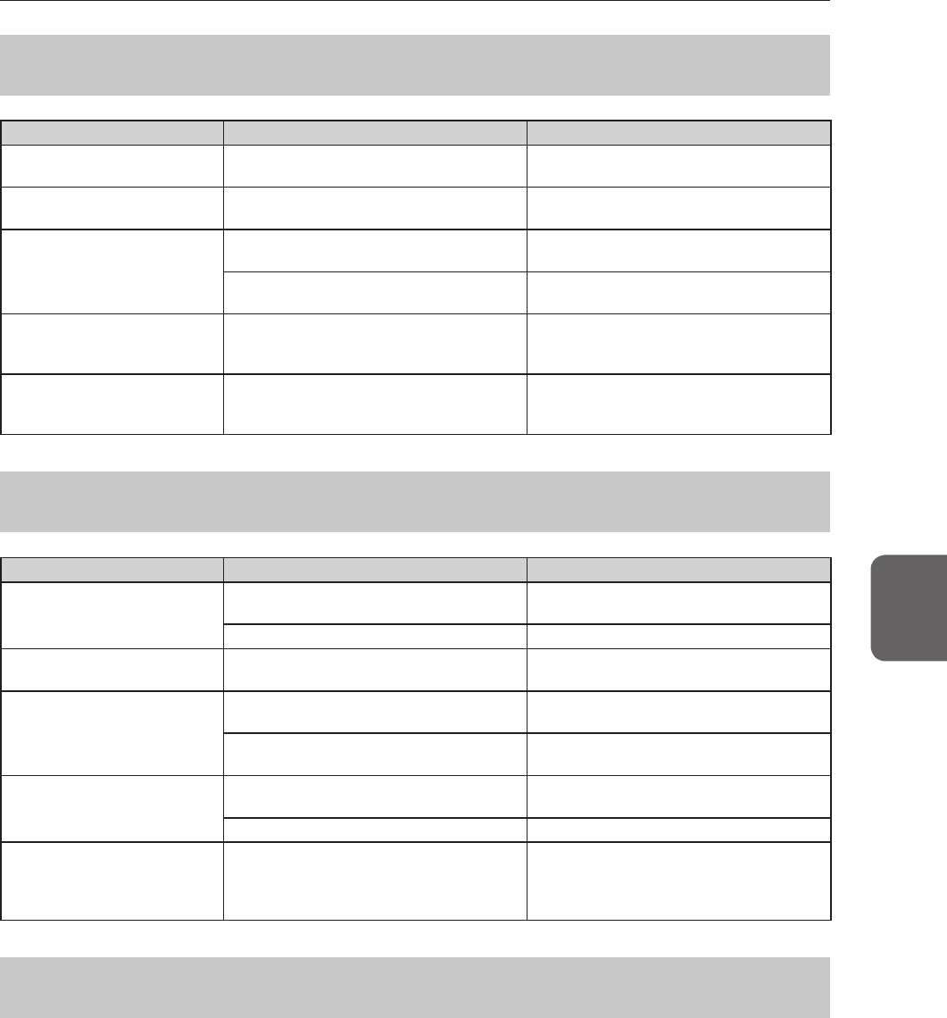
523 AeroDR Interface Unit2
Status Error description Corrective actions
PowerLED(green)doesnot
light. ACpowernotsupplied. Makesurethepowercableisconnectedcor-
rectly.
Feeding1/2LED(blue)doesnot
light.
Feeding1/2LED(blue)doesnotlighteven
whenconnectingtheAeroDRDetector.
MakesurethattheAeroDRI/FCableiscon-
nected
correctly
.
Communicationsaredown
betweendevices,andpower
LED(green)isoff.
Thepowerswitchisnoton.Or,thepower
cableisnotconnected.
MakesurethepowerswitchoftheAeroDR
InterfaceUnit2ison.Or,makesurethepower
cableisconnectedcorrectly.
TheAeroDRDetectorisbeing
usedwithwiredconnection,
butitisnotrecognizedonthe
imageprocessingcontroller,and
feeding1/2LEDs(blue)areoff.
TheAeroDRI/FCableisnotconnected. MakesurethattheAeroDRI/FCableis
connectedtotheAeroDRDetectorproperly.
Batteryisnotchargingwhile
theAeroDRDetectorisused
withwiredconnection(the
batterylevelonthebatterylevel
displayoftheimageprocessing
controllerdoesnotincrease),
andfeeding1/2LEDs(blue)are
off.
5.2Variousproblemsandcountermeasures
79
Chapter 5
524 AeroDR Battery Charger
Status Error description Corrective actions
StatusLED(green)doesnot
light. ACpowernotsupplied. Makesurethatthepowercableisconnected
correctly.
ErrorLED(orange)ison. - ContactKonicaMinoltatechnical
representatives.
WhentheAeroDRDetector
isset,theerrorLED(orange)
lights.
AeroDRDetectorwasinsertedthewrongway. ChecktheinsertionorientationoftheAeroDR
Detector.
TheAeroDRDetectorisnotsetcorrectly. MakesurethattheAeroDRDetectorisset
correctly.
AlthoughtheAeroDRDetectoris
inserted,chargingdoesnotstart,
andthestatusLED(green)isout.
ACpowernotsupplied. Makesurethatthepowercableisconnected
correctly.
AlthoughtheAeroDRDetectoris
inserted,itcannotberegistered,and
thestatusLED(green)isashing.
TheEthernetcableisdisconnected. MakesurethattheEthernetcableis
connectedcorrectly.
525 AeroDR Battery Charger2
Status Error description Corrective actions
StatusLED(green)doesnot
light.
ACpowernotsupplied. Makesurethatthepowercableisconnected
correctly.
Thepowerswitchisturnedoff. Turnonthepowerswitch.
ErrorLED(orange)ison. - ContactKonicaMinoltatechnicalrepresenta-
tives.
WhentheAeroDRDetectoris
set,theerrorLED(orange)lights.
AeroDRDetectorwasinsertedthewrongway. ChecktheinsertionorientationoftheAeroDR
Detector.
TheAeroDRDetectorisnotsetcorrectly. MakesurethattheAeroDRDetectorisset
correctly.
AlthoughtheAeroDRDetectoris
inserted,chargingdoesnotstart,
andthestatusLED(green)isout.
ACpowernotsupplied. Makesurethatthepowercableisconnected
correctly.
Thepowerswitchisturnedoff. Turnonthepowerswitch.
AlthoughtheAeroDRDetectoris
inserted,itcannotberegistered,
andthestatusLED(green)is
ashing.
TheEthernetcableisdisconnected. MakesurethattheEthernetcableisconnect-
edcorrectly.
526 Access Point
IfaproblemoccursintheAccessPoint,contactKonicaMinoltatechnicalrepresentatives.

5.2Variousproblemsandcountermeasures
80
527 Image processing controller/Images
Status Error description Corrective actions
Transverse(noise)hasgotten
intoallimagesacquiredfromthe
AeroDRDetector.
Thewiredcableisnotconnectedproperly.
Connectthewiredcablespringconnector
unithorizontallytothewiredconnectorofthe
AeroDRDetector.
Operationisnormal,butprob-
lemscanbeseenwithexposure
images.
Ithasbeenoccurringfrequentlysinceacer-
taintime. Performcalibration.
Thereistroubleinonly1image. Checktheexposuremethodandimagepro-
cessing.
Cannotexposewiththeimage
processingcontroller.
Theimageprocessingcontrollerdoesnot
becomeReady.
Checktheimageprocessingcontrollerstart
up.
Theiconsofdevicesusedontheimagepro-
cessingcontrollerarenotdisplayed.
Conrmthattheiconofthedevicetobeused
isdisplayedonthesystemmonitorscreen.
Whentheiconofthedeviceisnotdisplayed,
checkthatthedevicetobeusedisstarted.Or,
checkthattheEthernetcableisproperlycon-
nected.

81
Chapter 6
Maintenance
Thischapterdescribestheitemsthatrequireperiodicmaintenance.
82
61 Maintenance and inspection items
Thischapterdescribestheinspectionsandcleaning
requiredinordertomaintaintheuseofthisdevicein
anoptimumcondition.
HINT •••••••••••••••••••••••••••••••••••••
• "SimpleCheckQCforCS-7"isavailableforcheck-
ingofimagingquality.Pleasecontactourcustomer
serviceforthedetail.
•••••••••••••••••••••••••••••••••••••••••••••••••••••
611 Maintenance schedule
Themaintenanceandinspectionitemsthattheuser
shouldperformareasfollows.
Maintenance task
Mainte-
nance
interval
Checkingandcleaningthesurfaceofthe
AeroDRDetector
Weekly
CheckingforexternaldamagetotheAeroDR
Detector
Weekly
CleaningthespringconnectorsoftheAeroDR
BatteryCharger2,AeroDRI/FCableandAeroDR
UFCable
Weekly
Cleaningthewiredconnectionconnectorsofthe
AeroDRDetectorandAeroDRUFCable
Weekly
CleaningtheAeroDRBatteryCharger/
AeroDRBatteryCharger2
Weekly
FullchargeoftheAeroDRDetector Monthly
Calibration Every3
months
IMPORTANT
•••••••••••••••••••••••••••••••••••••
• Toensureoptimumuseofthisdevice,besureto
performperiodicmaintenance.
• Theabovetaskintervalsareestimatesandvary
accordingtousage.
•••••••••••••••••••••••••••••••••••••••••••••••••••••
Reference
•••••••••••••••••••••••••••••••••••••
• Forthecalibration,refertothe"UserToolOpera-
tionManual"orthe"OperationManual"oftheim-
ageprocessingcontroller.
•••••••••••••••••••••••••••••••••••••••••••••••••••••
612 Cleaning
Thecleaningmethodsoftherespectivedevicesareas
follows.
IMPORTANT
•••••••••••••••••••••••••••••••••••••
• Becarefulnottoapplyanycleaningchemicalor
liquidontothespringconnectors,thewiredcon-
nectionconnectors,andtheLEDs.
•
Donotcleanwithsharporhardmetalobjects.Ifyou
cannotremovestains,contactKonicaMinoltatechni-
calrepresentatives.
• Wearanddeformationoftheprotectivecoverwill
occurwiththeAeroDRDetectorduetothewayit
ishandled.Theprotectivecovercanbereplaced
forafeewhenthedamagebecomesextensive,so
contactKonicaMinoltatechnicalrepresentatives.
•••••••••••••••••••••••••••••••••••••••••••••••••••••
AeroDR Detector
• Cleantheexteriorwithasoftlint-freeclothdamp-
enedwithasmallamountofanhydrousethanoland
wrungwell.
• TocleanthegapbetweentheexterioroftheAero-
DRDetectorandtheprotectivecover,removedirt
usingacommercialplasticbrush.
Gapbetweentheexteriorand
theprotectivecover
Protectivecover
Exterior
IMPORTANT
•••••••••••••••••••••••••••••••••••••
• Ifyoudirectlyapplyorsprayanhydrousethanol
ontheAeroDRDetector,theliquidwillenterthe
AeroDRDetectorthroughexteriorgaps,causinga
failure.
•••••••••••••••••••••••••••••••••••••••••••••••••••••
83
6.1Maintenanceandinspectionitems
Chapter 6
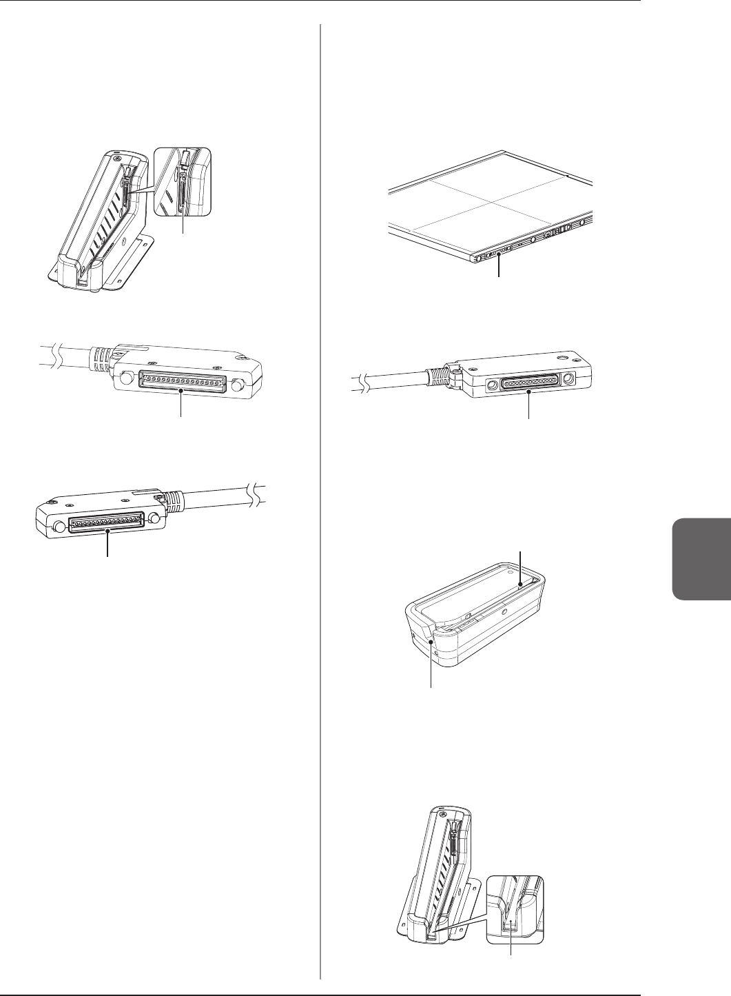
Spring connector
• Ifforeignmaterialhasadheredtothespringcon-
nectorsoftheAeroDRBatteryCharger2,AeroDR
I/FCableandAeroDRUFCable,removeitwitha
commercialplasticbrush.
AeroDR Battery Charger2
Springconnector
AeroDR I/F Cable
Springconnector
AeroDR UF Cable
Springconnector
Wired connection connector
• Ifforeignmaterialhasadheredtothewiredconnec-
tionconnectorsoftheAeroDRDetectorandAero-
DRUFCable,removeitwithacommercialplastic
brush.
AeroDR Detector
Wiredconnectionconnector
AeroDR UF Cable
Wiredconnectionconnector
AeroDR Battery Charger
• CleandustontheinserttableoftheAeroDRBattery
Chargerwithasoftlint-freeclothdampenedwithal-
coholorwaterandwrungwell.
AeroDRDetectorinserttable(side)
AeroDRDetectorinserttable(front)
AeroDR Battery Charger2
• CleandustontheinserttableoftheAeroDRBattery
Charger2withasoftlint-freeclothdampenedwith
alcoholorwaterandwrungwell.
AeroDRDetectorinserttable

84
6.1Maintenanceandinspectionitems
613 Disinfection of the
AeroDR Detector
Ifbodilyuidorbloodfromapatienthascontaminatedthe
surfaceoftheAeroDRDetector,disinfectwithasoftlint-
freeclothdampenedwithasmallquantityofthefollowing
disinfectantandwrungwell.
•Ethanolfordisinfection
•Isopropanolfordisinfection
•Commercialchlorinebleach,or0.5%hypochlorite
(10-folddilutionofhouseholdbleach)
IMPORTANT
•••••••••••••••••••••••••••••••••••••
• Bleachandhypochloritearecorrosive,sowashthe
bleachoffwelltoavoidcorrosion.
•
Becarefulnottoapplyanychemicalfordisinfection
ontothewiredconnectionconnectorsandtheLEDs.
• Ifyoudirectlyapplyorspraychemicalfordisinfec-
tionontheAeroDRDetector,thesolutionwillenter
theinstrumentthroughexteriorgaps,causinga
failure.
•••••••••••••••••••••••••••••••••••••••••••••••••••••
614 Consumables
IMPORTANT
•••••••••••••••••••••••••••••••••••••
• Refertoeachdevice’smanualforinformation
aboutperiodicreplacementpartsandconsumables
fortheimageprocessingcontroller,etc.
• Inparticular,continueduseofthebatterymayre-
sultindegradationandwear,anditmaynolonger
exhibitproperfunctioningcapabilities.Forextend-
ed,safeuse,itisnecessarytoreplacepartswhich
havebecomewornordegraded.
•••••••••••••••••••••••••••••••••••••••••••••••••••••

85
Chapter 7
Specications
Thischapterdescribesthespecicationsofthisdevice.
86
71 Specications
IMPORTANT
•••••••••••••••••••••••••••••••••••••••••••••••••••••••••••••••••••••••••••••••••••••••••••••••••••••••••
• Thefollowingspecicationsandgraphsdescribedbelowarenominalvalueswhichmaybedifferentfromactualvalues
andmayvarydependingonenvironmentandfrequencyofuse.(Thesearenottoprovideanyguarantees.)
• Allspecicationregardingbatteryisforafully-chargedbattery.
••••••••••••••••••••••••••••••••••••••••••••••••••••••••••••••••••••••••••••••••••••••••••••••••••••••••••••••••••••••••••••••••••••••••••••••••••••••••••••••••••••••••••••••••••••••••••••••••••••••••••••••••••••••••••••••••••••••••••••••
711 AeroDR Detector
Item Description
Productname(modelname)
AeroDR1417HQ(AeroDRP-11)
AeroDR1417S(AeroDRP-12)
AeroDR1717HQ(AeroDRP-21)
AeroDR1012HQ(AeroDRP-31)
AeroDRII1417HQ(AeroDRP-51)
Detectionmethod Indirectconversionmethod
Scintillator CsI(CesiumIodide)
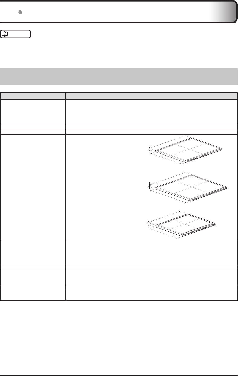
Externaldimensions
AeroDR1417HQ/AeroDR1417S/
AeroDRII1417HQ
383.7(W)×460.2(D)×15.9(H)mm
460.2mm
15.9mm
383.7mm
AeroDR1717HQ
459.8(W)×460.2(D)×15.9(H)mm 460.2mm
15.9mm
459.8mm
AeroDR1012HQ
281.8(W)×333.0(D)×15.9(H)mm 333.0mm
15.9mm
281.8mm
Weight
AeroDR1417HQ :2.9kg
AeroDR1417S :2.8kg
AeroDR1717HQ :3.6kg
AeroDR1012HQ :1.7kg
AeroDRII1417HQ:X.Xkg
Pixelsize 175um
Imageareasize
AeroDR1417HQ/AeroDR1417S/AeroDRII1417HQ:348.95×425.25mm(1,994×2,430pixels)
AeroDR1717HQ:424.9×424.9mm(2,428×2,428pixels)
AeroDR1012HQ:245.7×296.8mm(1,404×1,696pixels)
ADconversion 16bit(65,536gradients)
Usablegridfrequency 40lp/cm,34lp/cm
*Fordetails,referto"3.2.3 Precautionsforexposure".
87
7.1Specications
Chapter 7
Item Description
Maximumpatientweight
Pointload:150kg@Φ40mm
Faceload:300kg@effectiveimageareaoverall
*Deadweight,evenwhenloadedontheAeroDRDetector,hasnoeffectonimagesandthe
AeroDRDetector.ThemeasurementmethodisbasedonKMstandards.
Communication
AeroDR1417HQ/AeroDR1417S/AeroDR1717HQ/AeroDR1012HQ:
DedicatedwiredEthernetconnection/wirelessLAN(IEEE802.11acompliant)
AeroDRII1417HQ:
DedicatedwiredEthernetconnection/wirelessLAN(IEEE802.11a/b/g/hcompliant)
Drivepower Dedicatedpowercabledrive/batterydrive
WLANencryption Wirelessencryptionmethod :AES
Authenticationmethod :WPA2-PSK
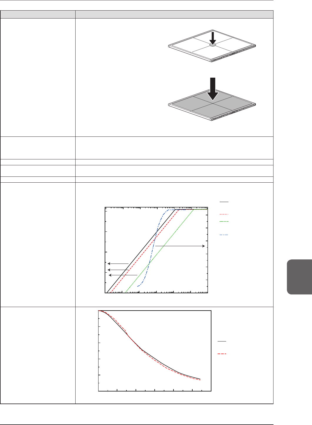
Patientdoses Patientdosesareequivalentto500-1000speedlm/screensystems.
Dynamicrange
4digits
Air kerma [µGy]
Density
Pixel value
Exposure dose [mR]
10001001010.10.01
1000
2000
3000
4000
1000100
10
10.10.010.001
2.5
3
1.5
2
0.5
1
0
AeroDR 1417HQ,
1717HQ, 1012HQ
REGIUS 210
(QR=250)
SRO-500/SR-G
0
AeroDR 1417S
MTF
Pre-sampled MTF
AeroDR 1417HQ,
1717HQ, 1012HQ
AeroDR 1417S
1
0.8
0.6
0.4
0.2
0012
0.5 1.5 2.5 3
Spatial frequency [cycle/mm]
88
7.1Specications
Item Description
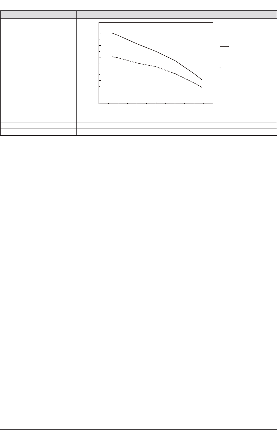
DQE
DQE [%]
AeroDR 1417HQ,
1717HQ, 1012HQ
1mR (8.7µGy)
AeroDR 1417S,
1mR (8.7µGy)
70
60
50
40
30
20
10
000.5 1.5 2.5 3
Spatial frequency [cycle/mm]
2
1
Requiredtimeforwired/wirelessswitching
Lessthan2seconds
Batterytype Lithiumioncapacitor
Batteryexpectedlifetime AbovetheAeroDRDetectorServicelife
89
7.1Specications
Chapter 7
712 AeroDR Interface Unit
Item Description
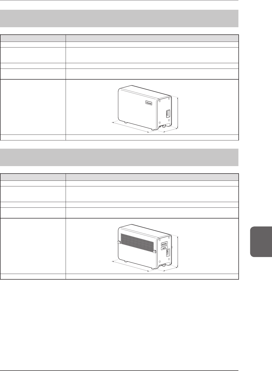
Productname(modelname) AeroDRInterfaceUnit(AeroDRB-1)
AmountofconnectableAeroDR
Detectors
Wiredconnection:Upto2
Wirelessconnection:Upto4
AccessPointisnecessarywhenoperatingwireless.
Powerrequirements AC100/110/115/120/200/220/230/240V±10%,singlephase50/60Hz
Powerconsumption WiththeAeroDRDetectorconnected :Approx.80VA(100-240V)
WithouttheAeroDRDetectorconnected:Approx.33VA(100-240V)
Externaldimensions
460(W)×180(D)×285(H)mm
180mm
460mm
285mm
Weight 11.5kg
713 AeroDR Interface Unit2
Item Description
Productname AeroDRInterfaceUnit2
AmountofconnectableAeroDR
Detectors
Wiredconnection:Upto2
Wirelessconnection:Upto4
AccessPointisnecessarywhenoperatingwireless.
Powerrequirements AC100/110/115/120/200/220/230/240V±10%,singlephase50/60Hz
Powerconsumption WiththeAeroDRDetectorconnected :Approx.80VA(100-240V)
WithouttheAeroDRDetectorconnected:Approx.33VA(100-240V)
Externaldimensions
460(W)×180(D)×285(H)mm
180mm
460mm
285mm
Weight 12.5kg
90
7.1Specications
714 AeroDR Generator Interface Unit
Item Description
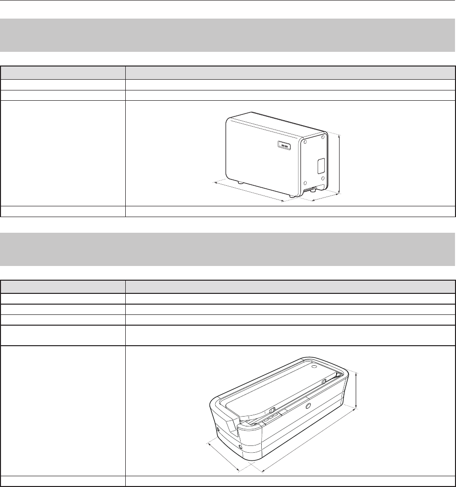
Productname(modelname) AeroDRGeneratorInterfaceUnit(AeroDRX-1)
Powersupply SuppliedfromtheAeroDRInterfaceUnitviatheEthernetcable.
Externaldimensions
460(W)×180(D)×285(H)mm
180mm
460mm
285mm
Weight 7.3kg
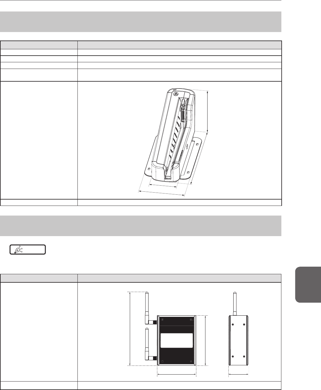
715 AeroDR Battery Charger
Item Description
Productname(modelname) AeroDRBatteryCharger(AeroDRD-1)
Batterychargingsystem Automaticcharging
Powerrequirements AC100/110/115/120/200/220/230/240V±10%,singlephase50/60Hz
Powerconsumption Charging:Approx.161VA(100-240V)
Standby:Approx.25VA(100-240V)
Externaldimensions
560(W)×250(D)×153(H)mm
153mm
560mm
250mm
Weight 7.2kg
91
7.1Specications
Chapter 7
716 AeroDR Battery Charger2
Item Description
Productname AeroDRBatteryCharger2
Batterychargingsystem Automaticcharging
Powerrequirements AC100/110/115/120/200/220/230/240V±10%,singlephase50/60Hz
Powerconsumption Charging:180VA(100-240V)
Standby:30VA(100-240V)
Externaldimensions
474.2(W)×200(D)×206.7(H)mm
206.7mm
474.2mm
120mm
200mm
Weight 6kg
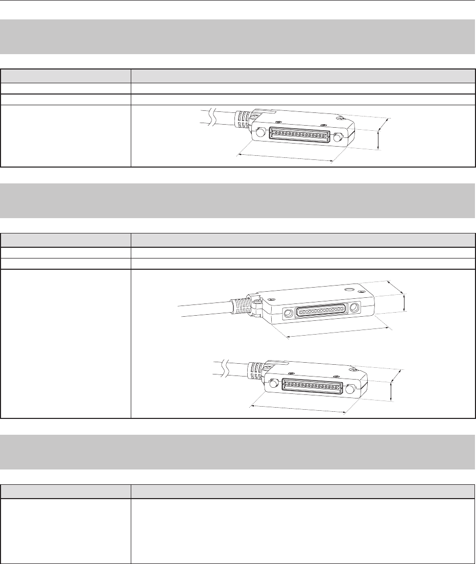
717 Access Point
HINT •••••••••••••••••••••••••••••••••••••••••••••••••••••••••••••••••••••••••••••••••••••••••••••••••••••
• Theillustrationsandexplanationmerelyshowsanexample.
•••••••••••••••••••••••••••••••••••••••••••••••••••••••••••••••••••••••••••••••••••••••••••••••••••••••••••••••••••••
Item Description
Externaldimensions
53.6(W)×135(H)×105(D)mm(withoutantenna)
198.5mm
105mm 53.6mm
135mm
Weight 850g
92
7.1Specications
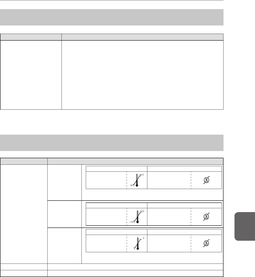
718 AeroDR I/F Cable
Item Description
Productname AeroDRI/FCable
Cablelength
10m/20m
Externaldimensions 14mm
79mm
42mm
719 AeroDR UF Cable
Item Description
Productname AeroDRUFCable
Cablelength
2m/5m
Externaldimensions
Wired connection connector (UIF) side
14mm
100mm
43mm
Spring connector (PIF) side
14mm
79mm
42mm
7110 AeroDR XG Cable
Item Description
Productname
AeroDRXGCableSet100V
AeroDRXGCableSet120V
AeroDRXGCableSet220V
AeroDRXGCableSet230V
AeroDRXGCableSet240V
AeroDRXGCableSetDC24V
93
7.1Specications
Chapter 7
7111 AeroDR S-SRM Cable
Item Description
Productname
AeroDRS-SRMCableGEX1
AeroDRS-SRMCableCPX1
AeroDRS-SRMCablePKX1
AeroDRS-SRMCableDEX1
AeroDRS-SRMCableHIX1
AeroDRS-SRMCableTOX1
AeroDRS-SRMCablePHX1
AeroDRS-SRMCableDEX2
AeroDRS-SRMCableTOX2
AeroDRS-SRMCableTOX3
AeroDRS-SRMCableTOX4
AeroDRS-SRMCableNC
AeroDRS-SRMCableQTX1
AeroDRS-SRMCableARX1
• AeroDRS-SRMCablesissubjecttochangewithoutnotice.
• OtherAeroDRS-SRMCablesmaybeaddedwithoutnotice.
• SomeAeroDRS-SRMCablesmaynotbeconrmedtocomplywithMDD.
7112 General AeroDR SYSTEM
Item Description
Recommendedstorage
andusageenvironment
conditions
Whenoperating
Temperature Humidity
10to30°C
35to80%RH
(ensurenowatercon-
densation) 35 %RH
80%RH
* Limitcontinuoususeinahotandhumidenvironment(35to37°C/95%orlower)
ofanincubatortowithin25minutes.
Whennotoper-
ating
Temperature Humidity
–10to40°C
20to90%RH
(ensurenowatercon-
densation) 20%RH
90%RH
Instorage/
transport
Temperature Humidity
–20to50°C*
-
20
50
20to90%RH
(ensurenowatercon-
densation) 20%RH
90%RH
*
However,performancewarrantyperiodwhenstoringat50°Cis6monthsafter
packing.
Classication SafetyIEC60601-1ClassI
Operationmode Continuousoperation

94
0197
Operation Manual
EN 01
A45YBD01EN01
20131220CT
DIRECT DIGITIZER AeroDR SYSTEM 2
Operation Manual
SYSTEM 2
DIRECT DIGITIZER