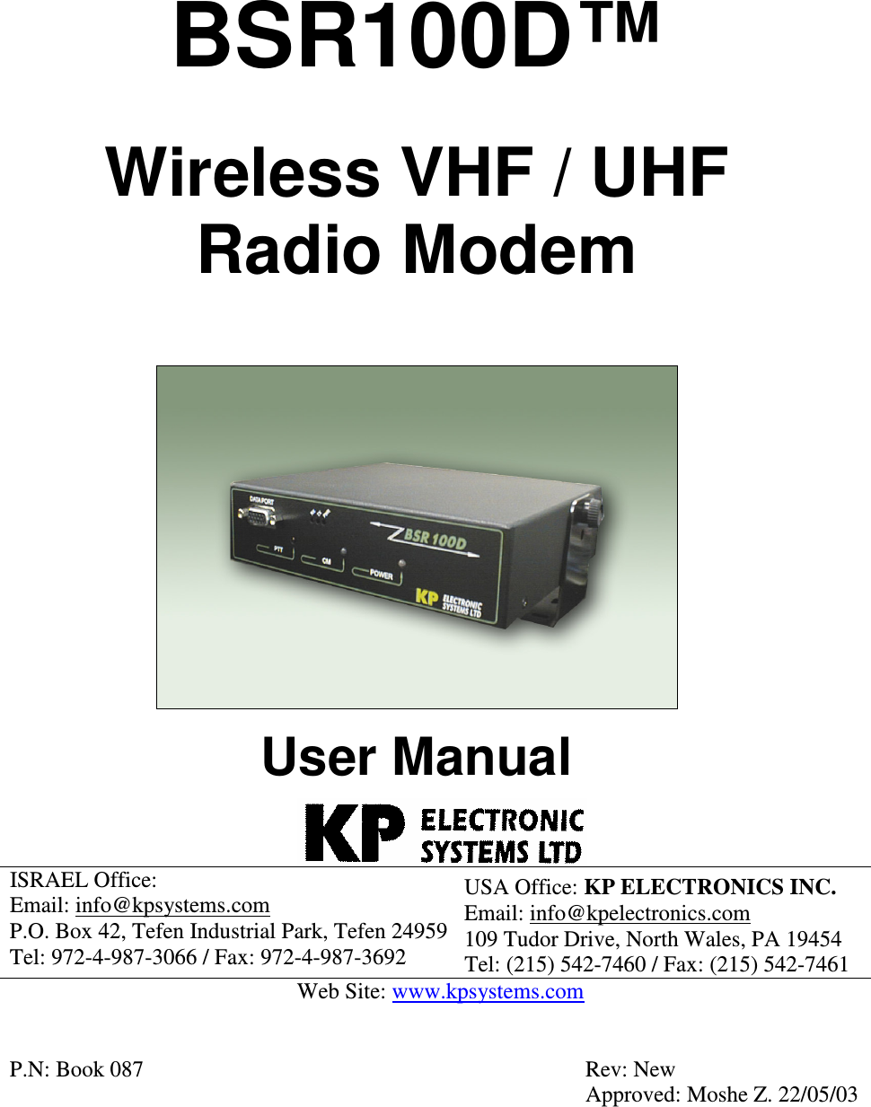
KP Electronic Systems KPBSR100D 10 WATT VHF RF MODEM User Manual
KP Electronic Systems Ltd 10 WATT VHF RF MODEM Users Manual
UserManual.wiki
>
KP Electronic Systems
>
KPBSR100D User Manual
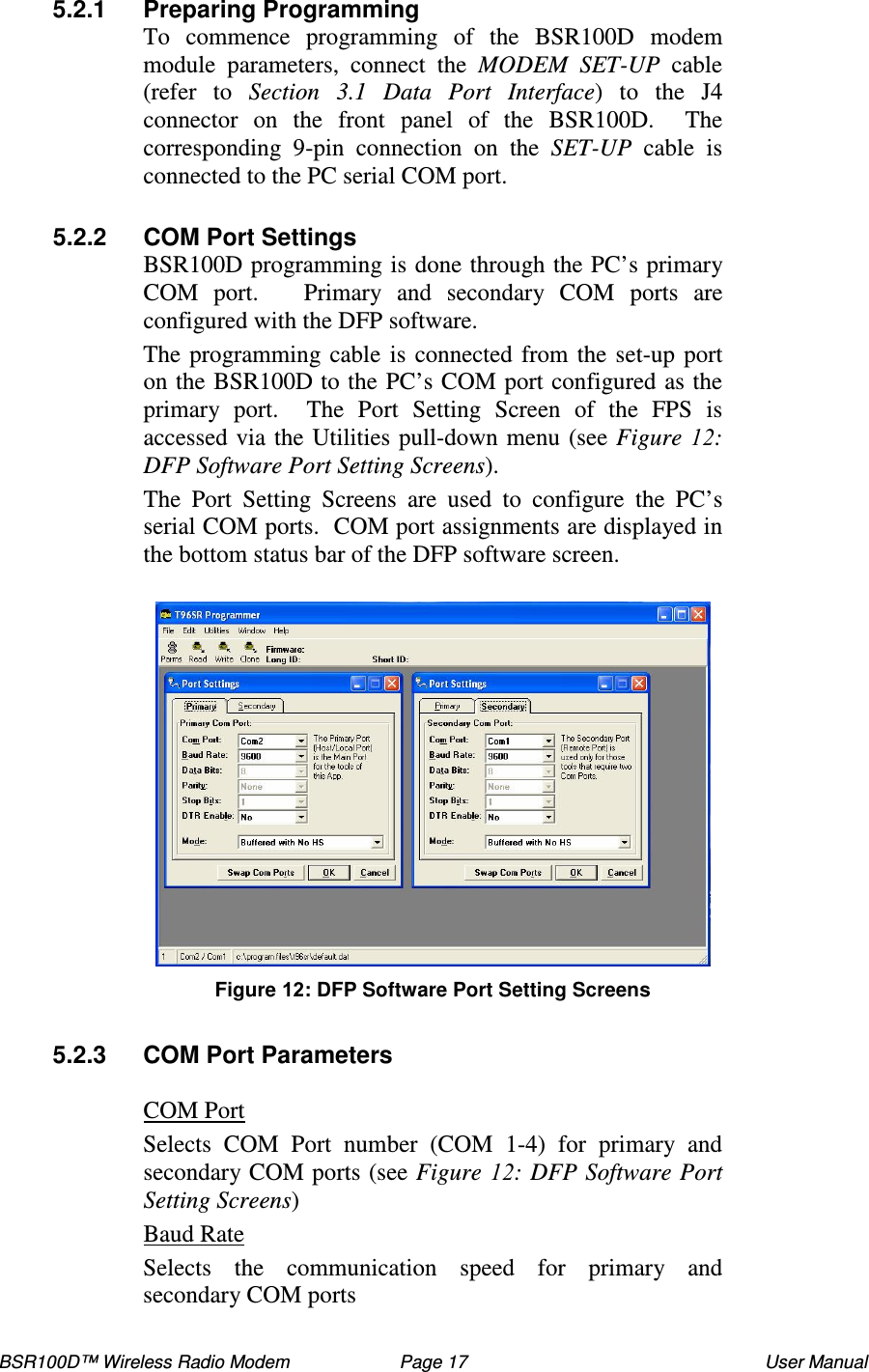
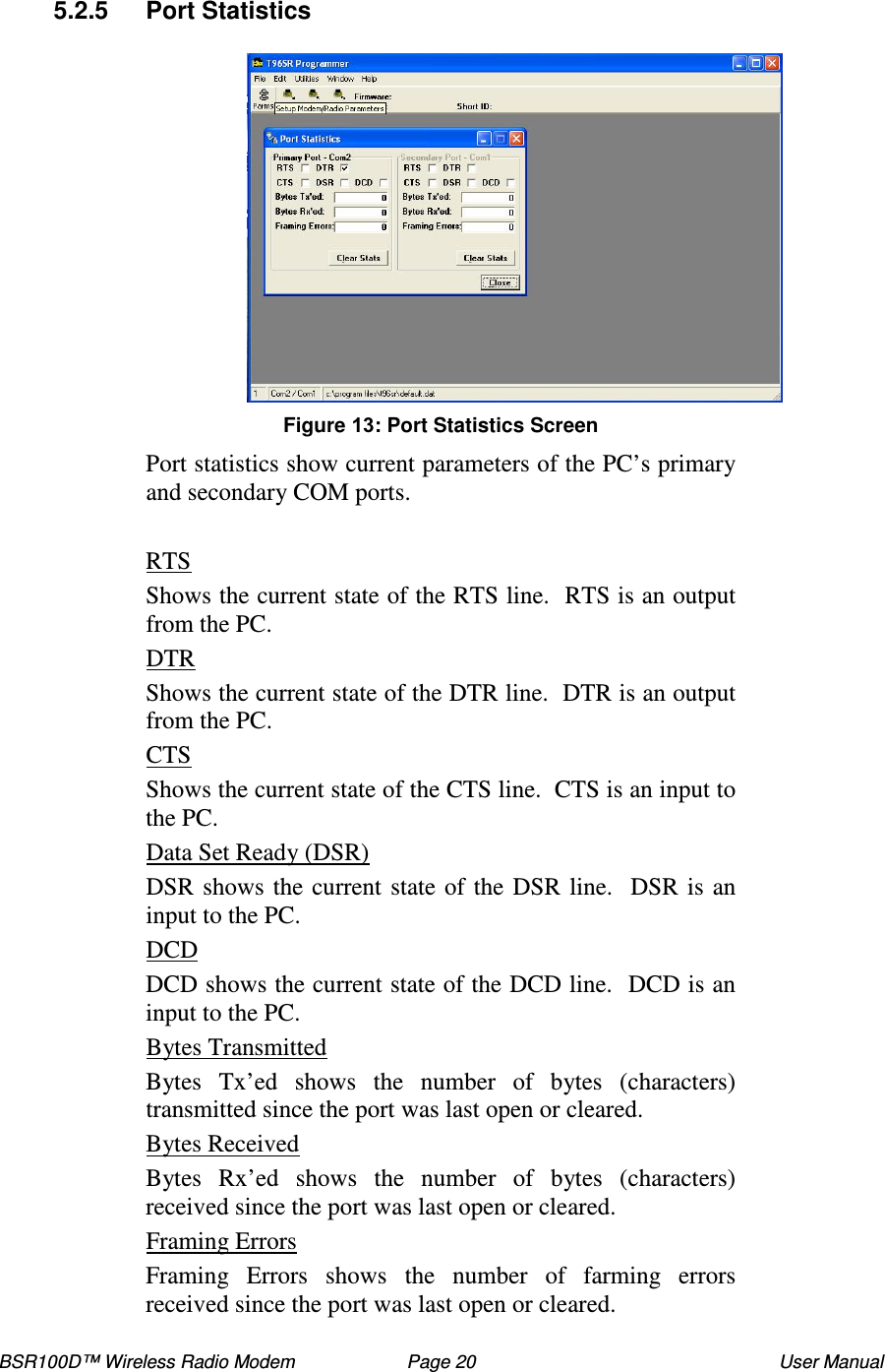
Users Manual
Navigation menu
Upload a User Manual
Namespaces
Wiki Guide
HTML
PDF
Info
Views
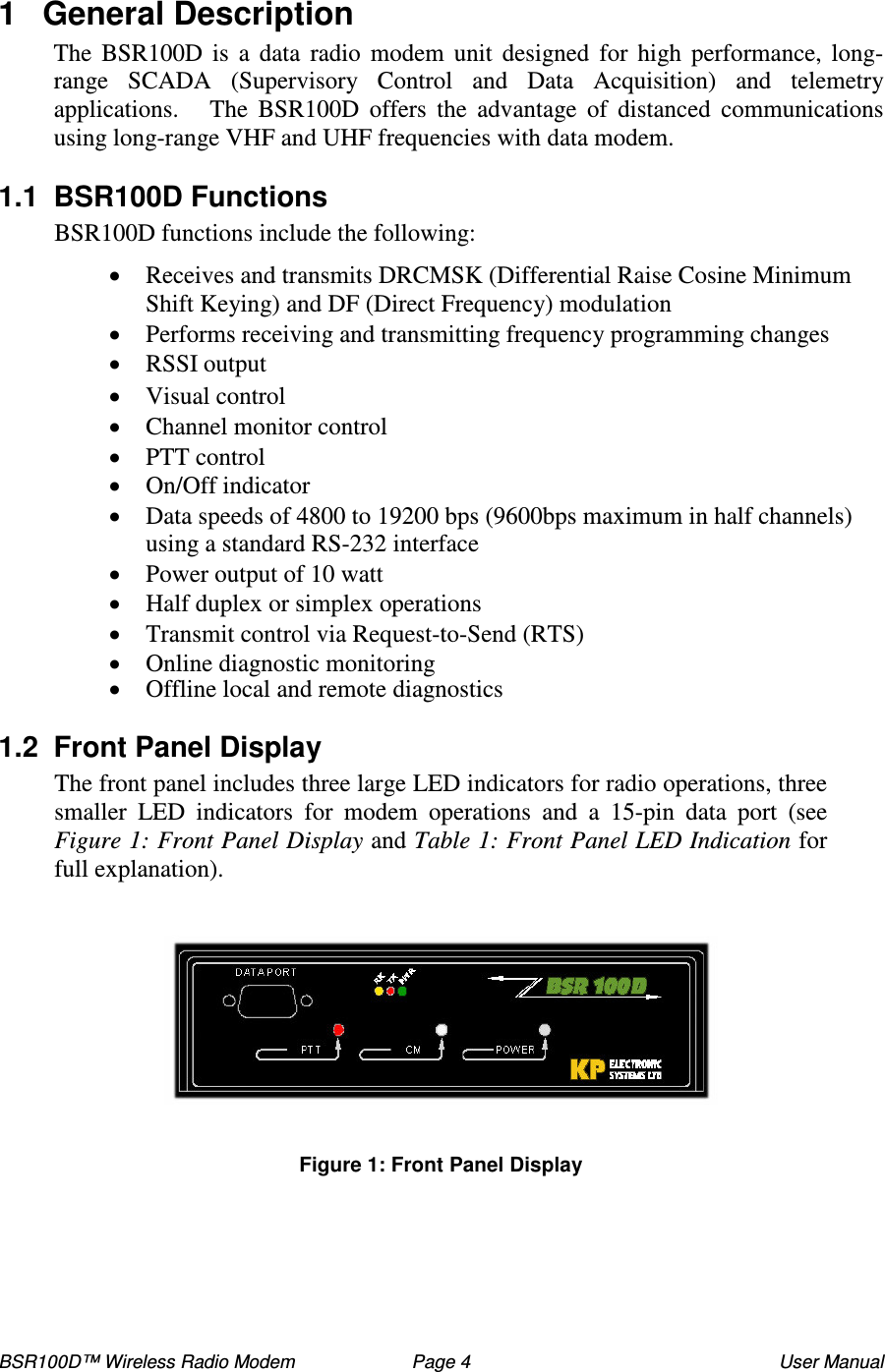
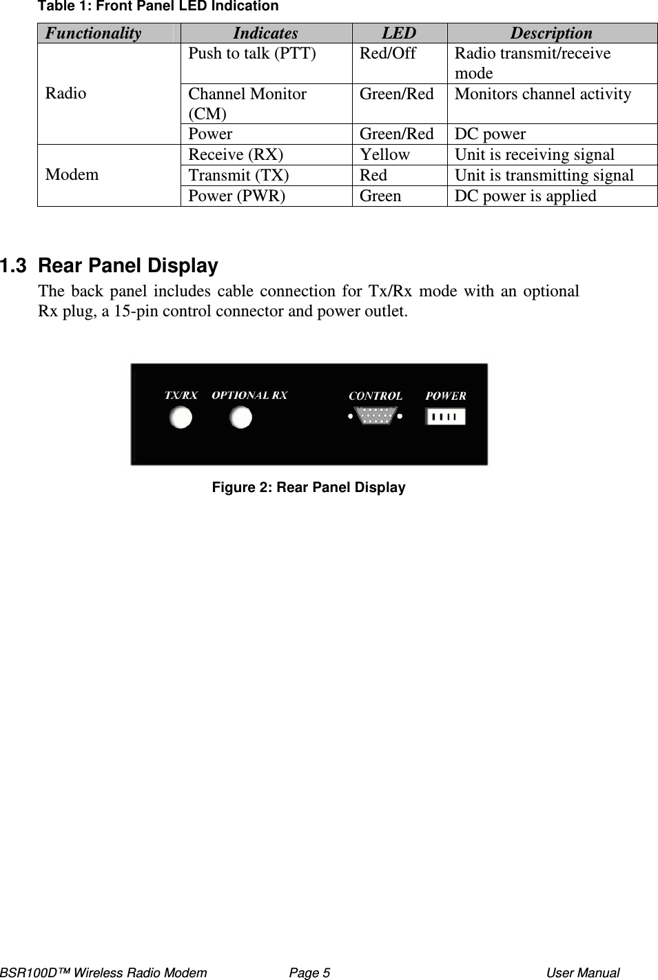
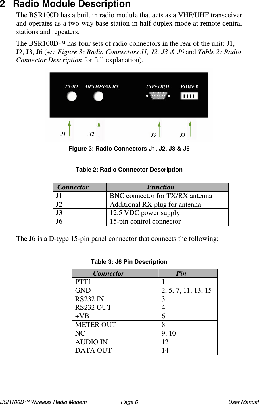
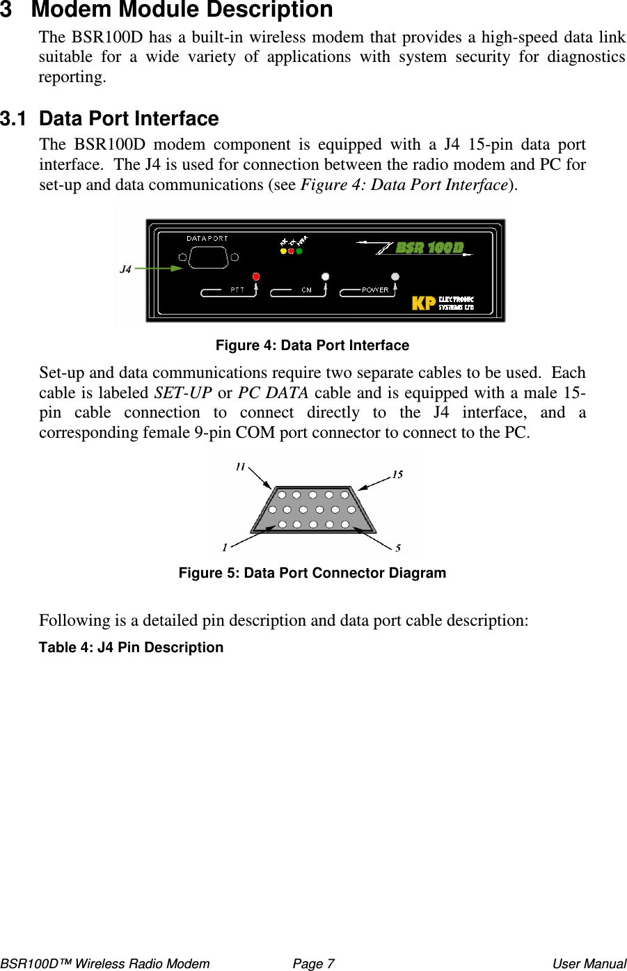
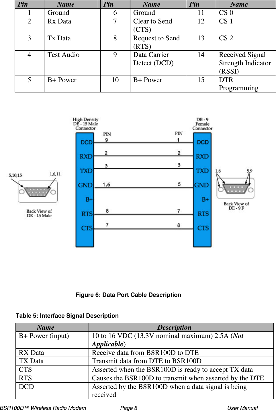
User Manual
Discussion / Help
Navigation