KP Electronic Systems KPRFM200A Base Station Transceiver User Manual
KP Electronic Systems Ltd Base Station Transceiver
User Manual
KP Electronic Systems, Ltd.
RFM200 – User Manual
Rev: 0.1
Page 1 of 8
KP Proprietary Information
KP
Electronic Systems, Ltd.
RFM200
User Manual

KP Electronic Systems, Ltd.
RFM200 – User Manual
Rev: 0.1
Page 2 of 8
KP Proprietary Information
Revision History:
Rev.
Date
Description
Reason of change
Affect Paragraph/
Documents
Initiator
0.1
Initial release
Efi
Contents
1. General: ................................................................................................................................................. 3
2. Radio Specification: ............................................................................................................................... 4
3. Power Supply: ....................................................................................................................................... 5
4. LED indication: ...................................................................................................................................... 6
5. Radio RF calibration: ............................................................................................................................. 6
6. Parameter Setting by GUP: ................................................................................................................... 6
7. Mechanical Description and Dimension: .............................................................................................. 8

KP Electronic Systems, Ltd.
RFM200 – User Manual
Rev: 0.1
Page 3 of 8
KP Proprietary Information
1. General:
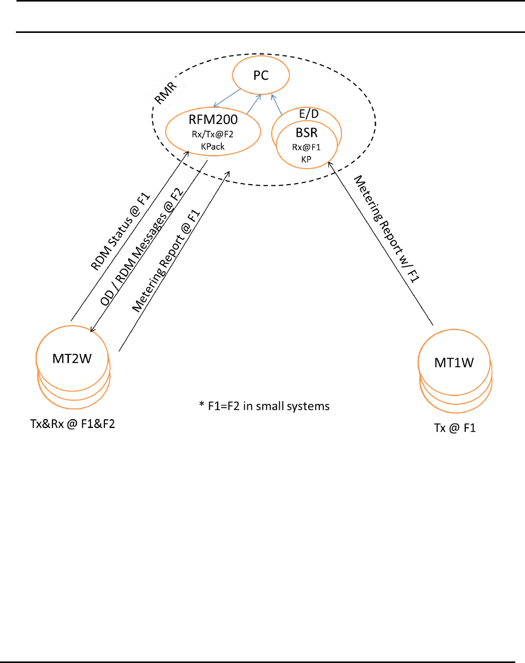
The RFM200 is used as RF modem which holds the RF communication between he RMR and the
metering devices. The interface with the PC is done through USB Type B for data exchange and Mini
Type B for parameter setting. The RFM radio is high power 5W VHF radio covers the 150 to 174MHz RF
band. The RFM20 is power from 12.5V power supply that is backed up with Lid Accid 12V battery.
KP Electronic Systems, Ltd.
RFM200 – User Manual
Rev: 0.1
Page 4 of 8
KP Proprietary Information
2. Radio Specification:
• Supply voltage……………………... 12.5v typical. Min/max = 10/15Vdc
• Low battery indication……………… 9.5V
• RF data rate ……….………….……. 4.8Kbps at 6.25 channels.
• GUP data rate ………………………..9.6Kbps
KP Electronic Systems, Ltd.
RFM200 – User Manual
Rev: 0.1
Page 5 of 8
KP Proprietary Information
• PC data rate…………………………38.4Kbps for data and 9.6Kbps for parameter
setting
• RF freq set by GUP………………….150 to 174MHz.
• Radio power…………………………5W
• Tx current……………………………1.5 amper
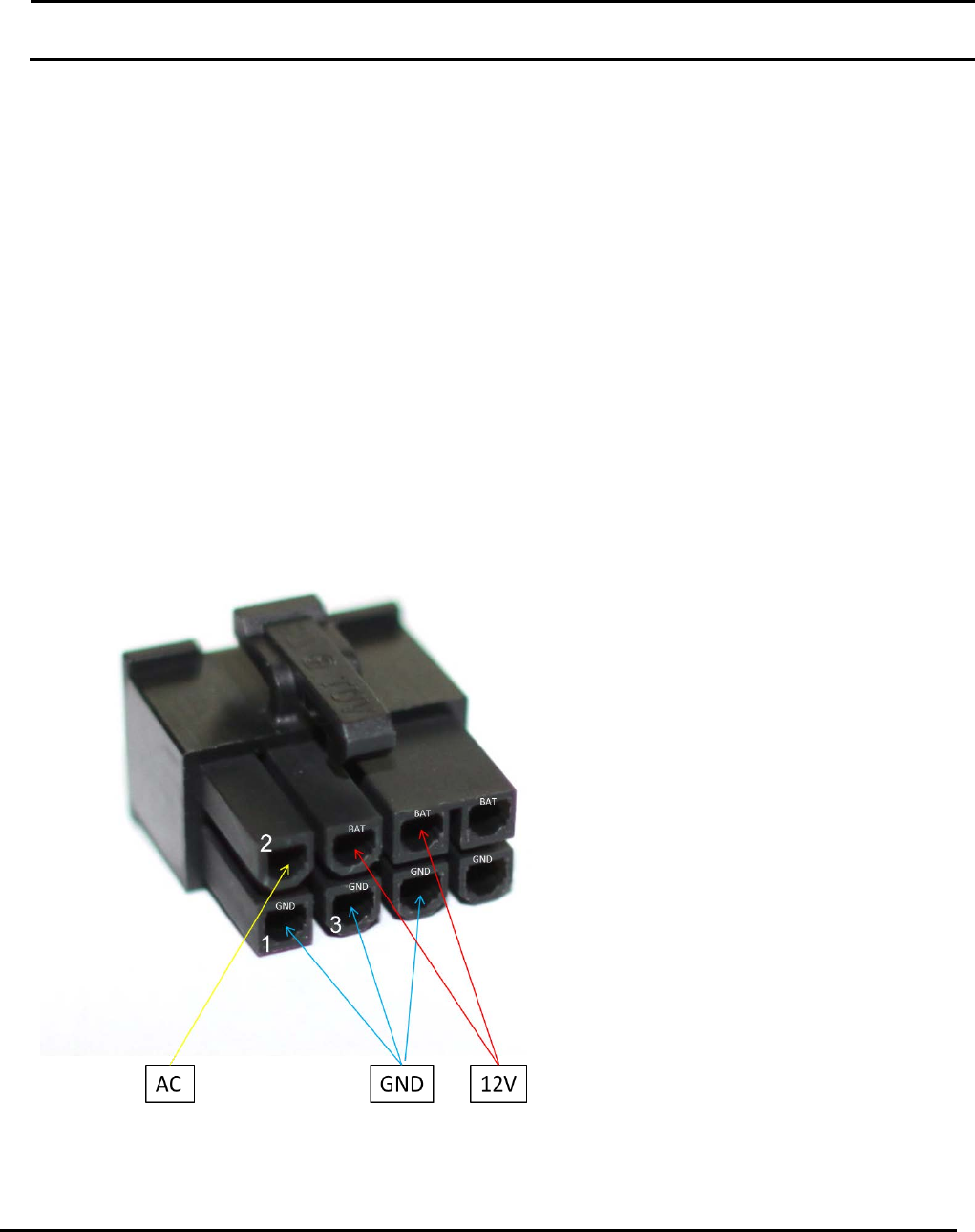
3. Power Supply:
The external power supply is through 8 pin connector (KP P/N CON147). The external cable is KP P/N
CAB222. The external connector pin type is showed in the next image:

KP Electronic Systems, Ltd.
RFM200 – User Manual
Rev: 0.1
Page 6 of 8
KP Proprietary Information
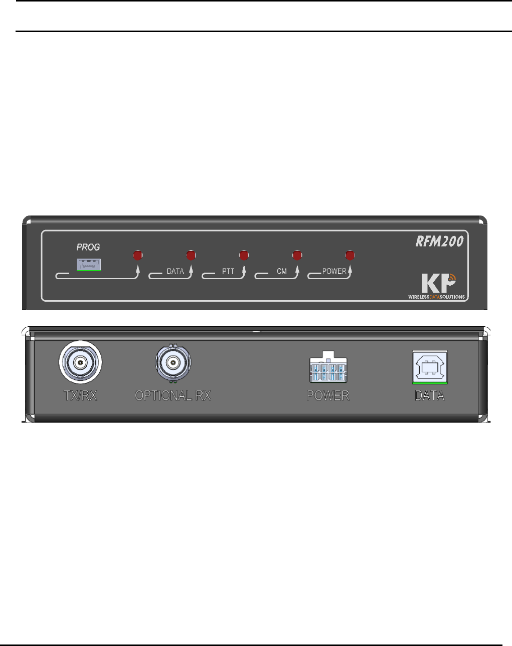
4. LED indication:
The POWER LED indicates that the power is fed from external power supply.
The CM LED indicates that the RF channel is busy when a signal above -107dBm is detected.
The PTT LED is turn on whenever the radio transmits (RF).
The DATA LED indicates when data is exchanged between the PC and the RFM200.
The PROG LED indicated that prameters are trsnmitted between the PC and the RFM200.
5. Radio RF calibration:
The radio power and radio deviation are fixed and can’t be changed. The frequency is based on
TCXO 32.000MHz that has maximum 1ppm temperature stability. The procedure of frequency
calibration is by try and error loop i.e. measuring the RFM200 carrier transition frequency error,
setting the freq offset and measure the frequency again until the frequency error is less than
0.5ppm.
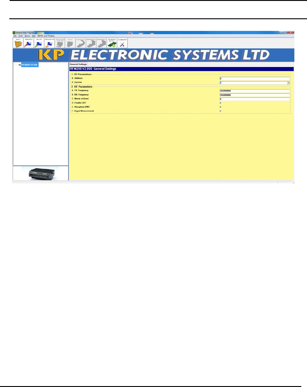
6. Parameter Setting by GUP:
The frequency is set by the GUP PC application through the front panel micro USB connector.
KP Electronic Systems, Ltd.
RFM200 – User Manual
Rev: 0.1
Page 7 of 8
KP Proprietary Information
KP Electronic Systems, Ltd.
RFM200 – User Manual
Rev: 0.1
Page 8 of 8
KP Proprietary Information
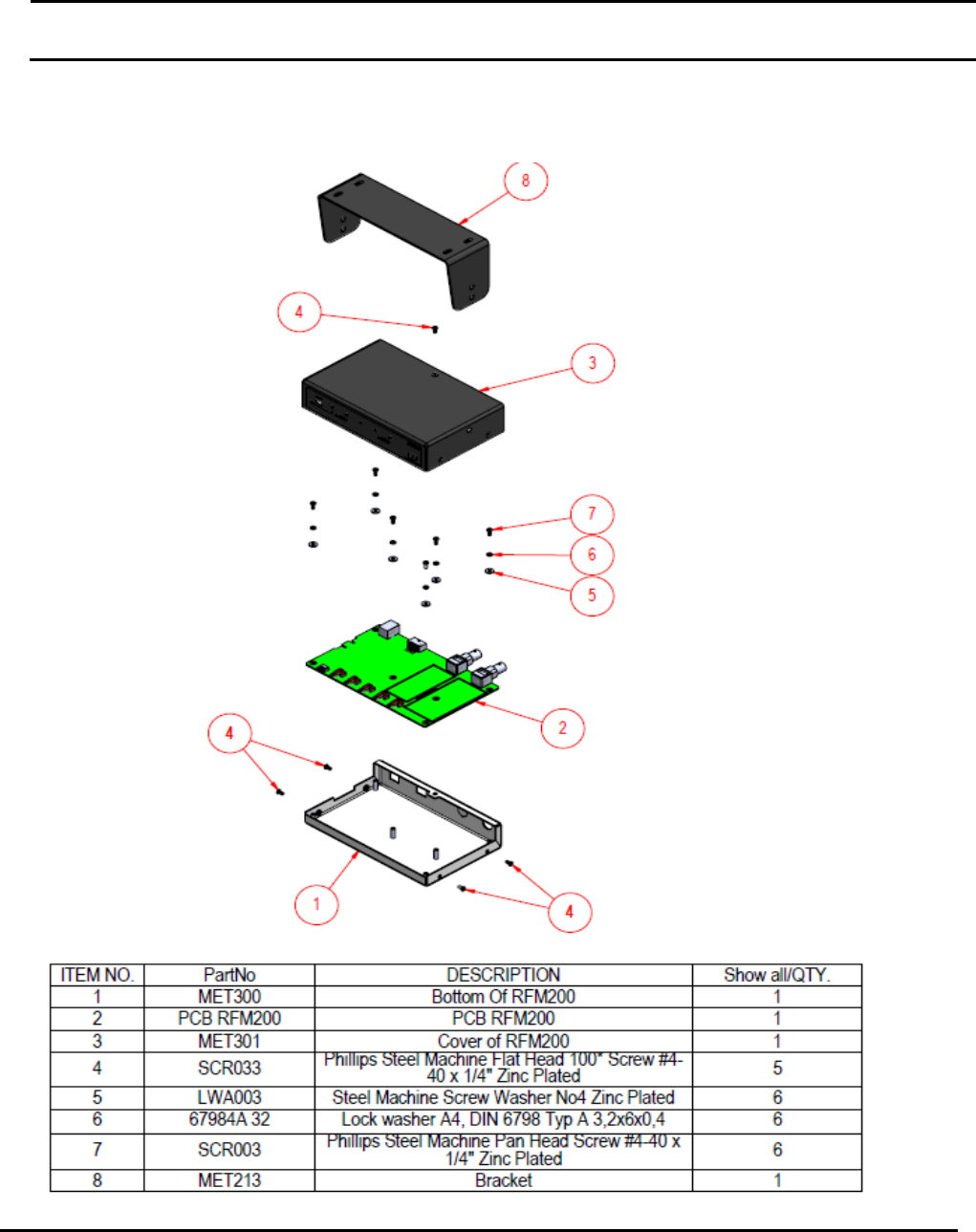
7. Mechanical Description and Dimension: