KROHNE BM702 Part 90.103 Fluid level sensor User Manual Manual
Krohne America Inc Part 90.103 Fluid level sensor Manual
UserManual.wiki
>
KROHNE
>
BM702 User Manual
>
Users Manual
Contents
1.
Test report
2.
Users Manual
Users Manual
Navigation menu
Upload a User Manual
Namespaces
Wiki Guide
HTML
PDF
Info
Views
User Manual
Discussion / Help
Navigation
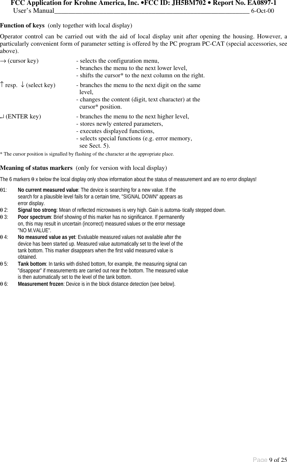
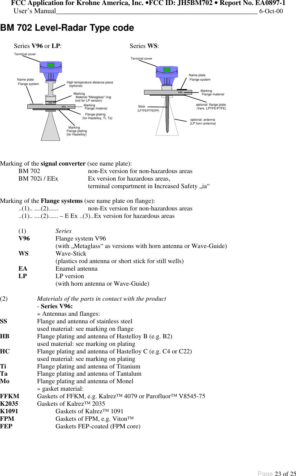
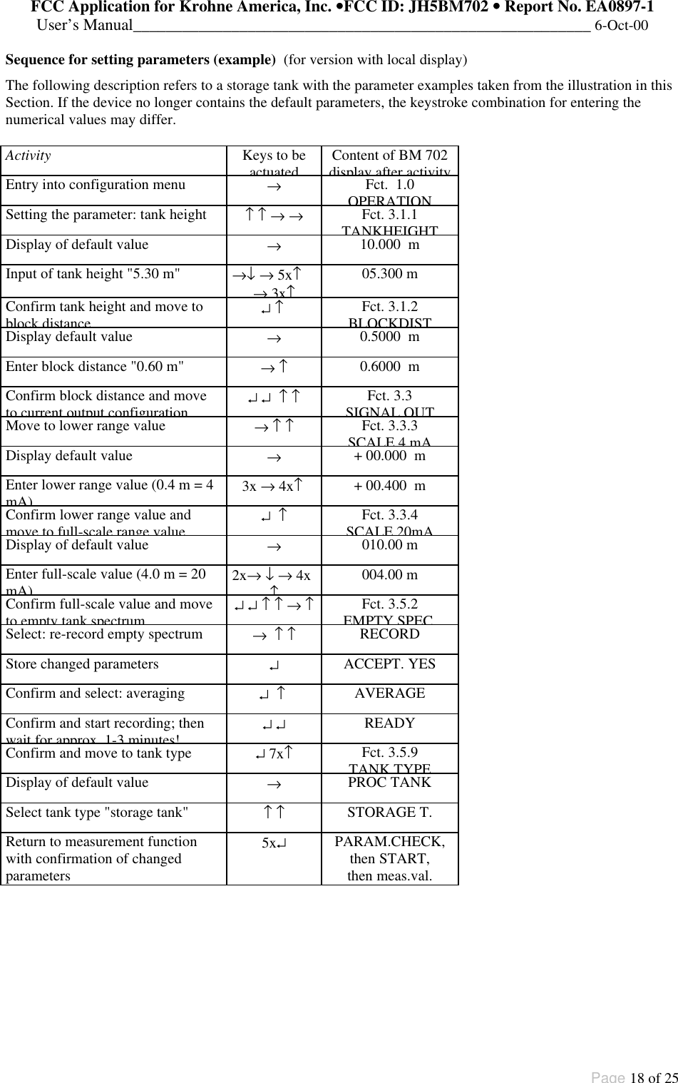
![FCC Application for Krohne America, Inc. ••FCC ID: JH5BM702 •• Report No. EA0897-1User’s Manual________________________________________________________ 6-Oct-00Page 11 of 25Description of functionsThe table on the following 3 pages provides an overview of all parameters that can be set in the configurationmenu.This is followed by more precise explanations of some functions and a typical configuration.Configuration menu (version 7.00)Function (Fct.) Input range Description1.0 OPERATION1.1 DISPLAY1.1.1 FCT.DISP identical with 3.2.11.1.2 UNIT.LENGTH identical with 3.2.21.1.3 UNIT.CONV. identical with 3.2.32.0 TEST2.1 HARDWARE2.1.1 MASTER Master hardware test.2.1.2 DISPLAY Display hardware test.2.1.3 STATUS Status information forService2.2 CUR.OUTP.I2.2.1 VALUE I Value display Display of actual value ofthe current output.2.2.2 TEST I Select 3.6 mA/4 mA/6 mA/...... 20 mA/22 mA Output of selected value tothe current output. Withsafety query.2.4 FIRMWARE2.4.1 MASTER Display Display of masterfirmware version.3.0 INSTALL.3.1 BASIS.PARAM3.1.1 TANKHEIGHT Select unit m/cm/mm/inch/FtEnter 0.50 ... 20.00 [m]Enter tank height (seeexplanatory notes).The unit entered here isalso used for all otherlength entries.3.1.2 BLOCKDIST Enter 0.10 [m] ... tank height Enter block distance =non-measurable rangebelow bottom edge offlange (see explanatorynotes).3.1.3 ANTENNA SelectSTANDARD WAVE-STICKSelect antenna type.WAVE-STICK for allWave-Stick versions,except type "SW" forstillwells.All other = STANDARD.3.1.4 ANT.EXTENS. Enter 0.00 [m] ... tankheight Enter length of antennaextension (not for Wave-Stick: set to= 0)3.1.5 DIST.PIECE Enter 0 ... 2000 [mm] Enter length of distancepiece above flange (hightemp. version = 120 mm).3.1.6 STILLWELL Select NO /YESIf “YES“: enter 25 ... 200[mm]Selection: without orwith still well.With still well: enterinside diameter in[mm] (compensatesdifferent wave speedsin still wells)](https://usermanual.wiki/KROHNE/BM702.Users-Manual/User-Guide-120815-Page-11.png)
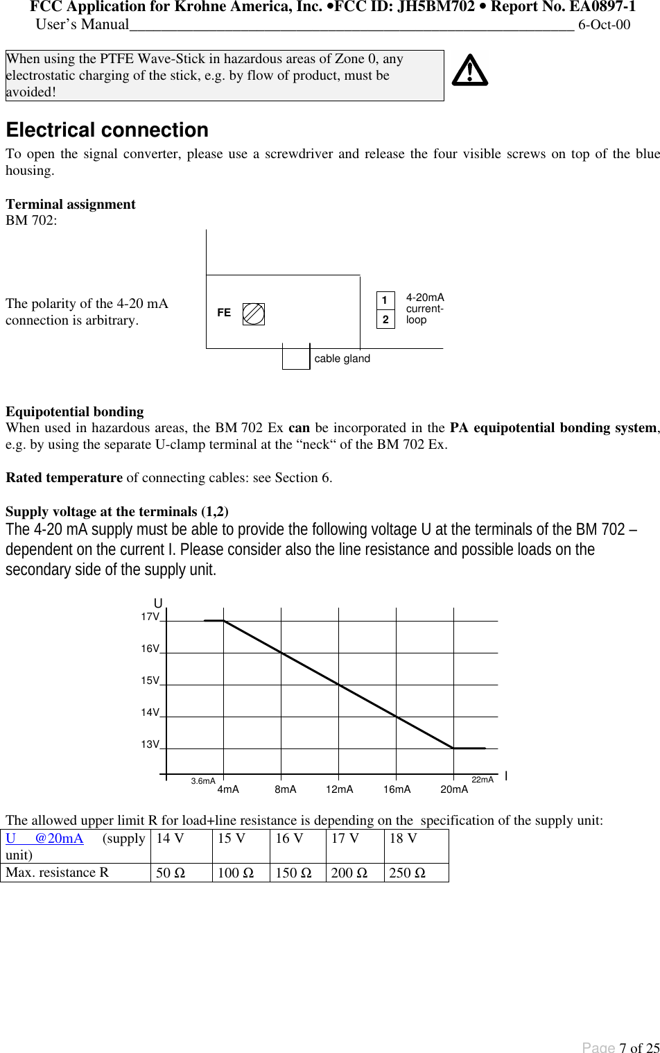
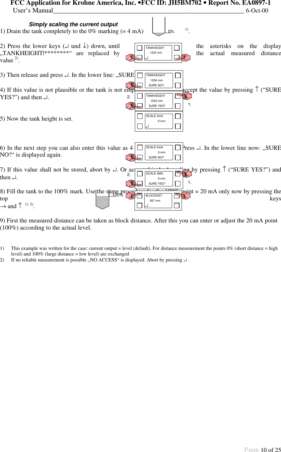
![FCC Application for Krohne America, Inc. ••FCC ID: JH5BM702 •• Report No. EA0897-1User’s Manual________________________________________________________ 6-Oct-00Page 12 of 25Function (Fct.) Input range Description3.1.7 REF.OFFSET Enter -10.00...0...+10.00[m] Reference offset isadded to measureddistance values.3.1.8 TB.OFFSET Enter-100.00...0...+100.00[m] Tank bottom offset isadded to measuredlevel values.3.2 DISPLAY3.2.1 FCT.DISP SelectLEVEL DISTANCECONVERSIONSelect function ofdisplay (value to bedisplayed). See alsoexplanatory notes.3.2.2 UNIT.LENGTHSelectm/cm/mm/ inch/Ft/PERCENT/BARGRAPHSelect unit for lengthvalue to be displayed(only for level anddistance).3.2.3 UNIT.CONV. Select m3/l(Liter)/USGal/GB Gal/Ft3/bbl/PERCENT/BARGRAPH/USER UNITSelect unit for conver-sion value to be dis-played (“volumetable“).(see explanatorynotes)3.2.4 USER UNIT Text entry 10 characters Enter user-defined unitfor the conversiontable.3.2.5 ERROR MSG. SelectNO/YES Select whether errormessages to be shownin display.3.3 SIGNALOUT3.3.1 FUNCTION I SelectOFF/LEVEL/DISTANCE/ CONVERSION/SW.OUTP.Select function of thecurrent output.3.3.2 RANGE I Select 4-20mA 4-20mA/E3.64-20mA/E22Select range/errorstatus for the currentoutput (hold last valueor 3.6 mA/22mA inerror status)3.3.3 SCALE 4mA Enter -200.00 ... +200.00[m] 0.00 ... 99999.99 [m3]Enter lower measuringrange value for thecurrent output (4 mA).(see explanatorynotes)3.3.4 SCALE 20mA Enter -200.00 ... +200.00[m] 0.00 ... 99999.99 [m3]Enter full-scale rangevalue for the currentoutput (20 mA).(see explanatorynotes)3.3.5 BAUDRATE Select 1200Bd Baud rate for HARTcommunication (donot change!).3.3.6 ADDRESS Enter 0 ...255 Enter device address.(for HART multidrop)](https://usermanual.wiki/KROHNE/BM702.Users-Manual/User-Guide-120815-Page-12.png)
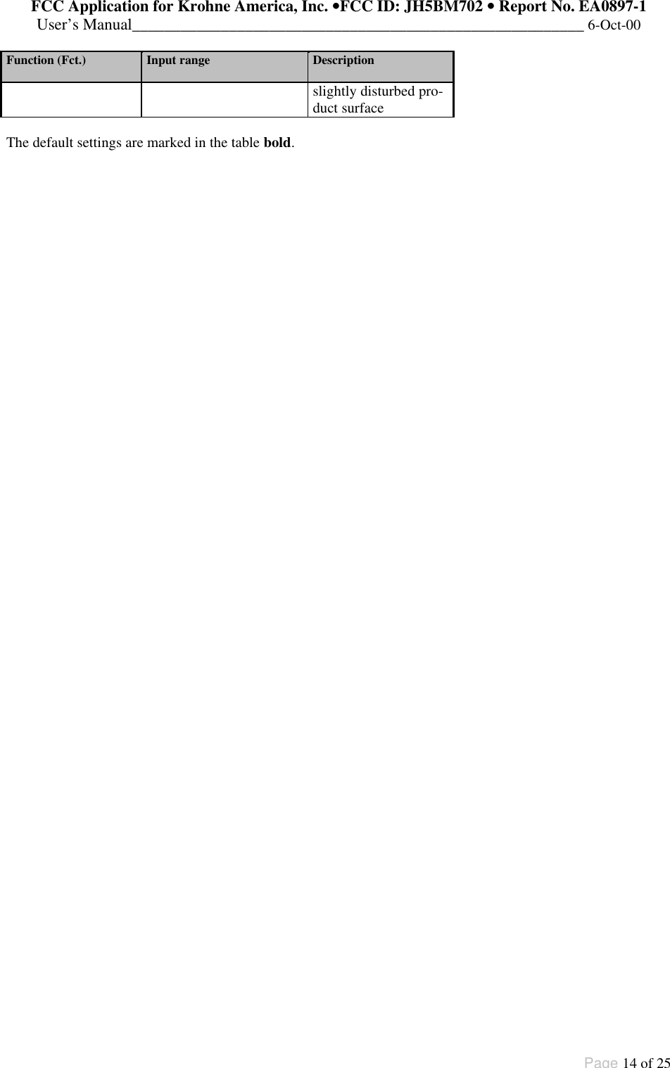
![FCC Application for Krohne America, Inc. ••FCC ID: JH5BM702 •• Report No. EA0897-1User’s Manual________________________________________________________ 6-Oct-00Page 13 of 25Function (Fct.) Input range Description3.3.7 PROTOCOL SelectHART/KROHNE-PC Selectcommunicationsprotocol3.4 USER DATA3.4.1 LANGUAGE Select GB-USA/D/F/I/E/P/S Select language for theoptional display.3.4.2 ENTRYCODE 1 SelectNO/YES Switch the accesslockout on/off.If YES, for everyaccess a 9-digit entrycode on the 4 keys isnecessary.3.4.3 CODE 1 Enter code(RRREEEUUU)Enter the entry codefor access lockout.3.4.4 LOCATION Enter text (8 characters) Enter a deviceidentifier.3.5 APPLICAT.3.5.1 AUTOTANKH. Special function Automaticdetermination of tankheight(see explanatorynotes).3.5.2 EMPTY.SPEC.SelectOFF/ON/RECORDRecording the profileof the empty tank(empty-tank spectrum)(see explanatorynotes).3.5.3 TIMECONST. Value 1...10...100[s] Enter time constant formeasured-valuefiltering3.5.4 TRACING.VEL.Value 0.01...0.50...10.00[m/Min]Enter the maximumrate of change in levelthat can occur inoperation.3.5.5 MULT.REFL. SelectNO/YES Switch the multi-reflection identifieron/off.3.5.6 BD-DETECT. SelectNO/YES Switch the blockdistance (overfill)identifier on/off (seeexplanatory notes).3.5.7 FUNCT. FTB SelectOFF/PARTIALSelect function of tankbottom tracing system(see explanatorynotes).3.5.8 EPSILON R Enter 1.1000 ... 8.0000 Enter relativepermittivity of product(only for Fct. 3.5.7)3.5.9 TANKTYPE SelectSTORAGE T./PROC TANKSelect tank type.STORAGE T. =smooth productsurfacePROC TANK =](https://usermanual.wiki/KROHNE/BM702.Users-Manual/User-Guide-120815-Page-13.png)
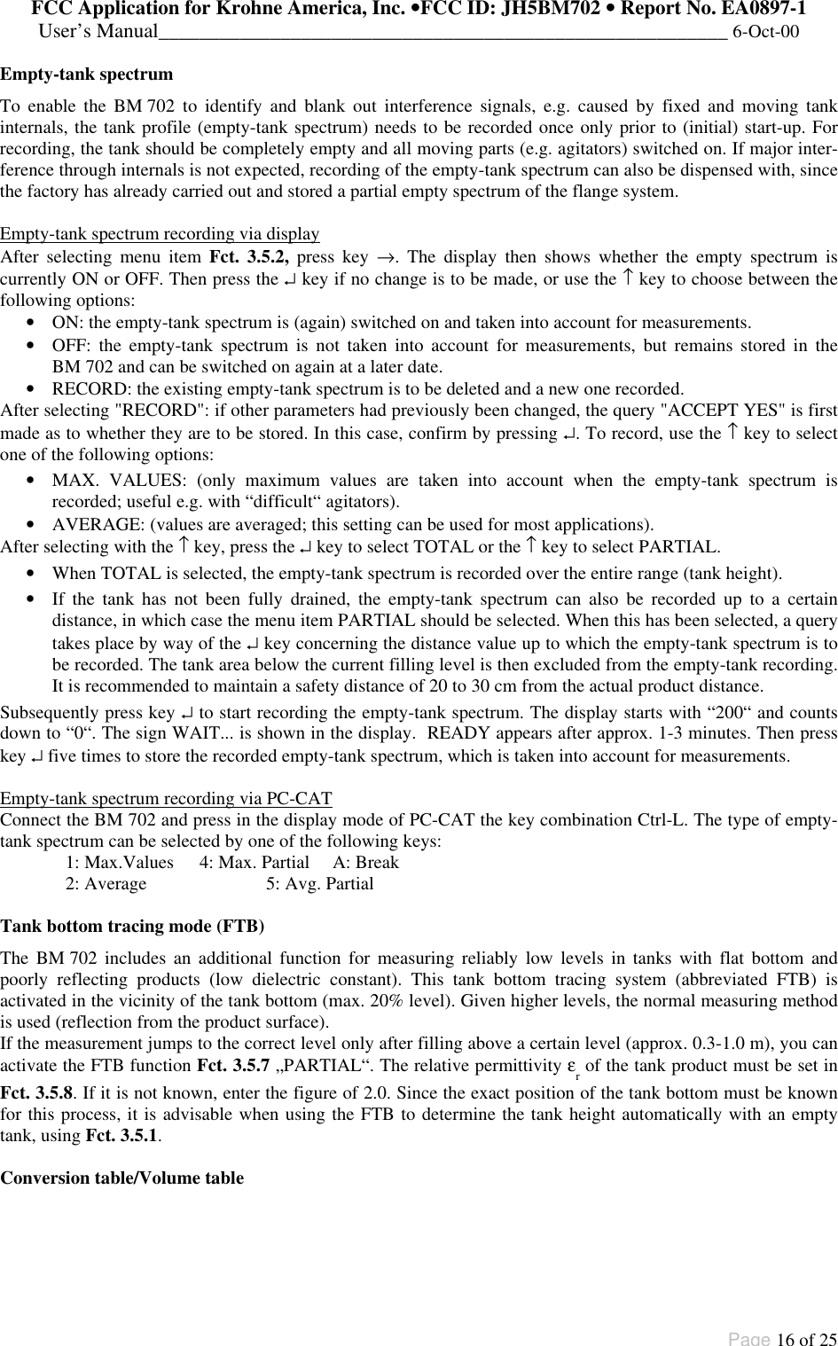
![FCC Application for Krohne America, Inc. ••FCC ID: JH5BM702 •• Report No. EA0897-1User’s Manual________________________________________________________ 6-Oct-00Page 15 of 25Explanatory notesTank heightThe tank height (Fct. 3.1.1) for the BM 702 is defined as the distance between the top edge of the tankconnecting flange and the bottom reference point. The bottom reference point is that “point“ in the tank on whichthe microwaves of the BM 702 hit and from which they are reflected. This may be the tank bottom (symmetricaltank with flat bottom) or the non-horizontal part of the bottom (e.g. tank with dished bottom) or an additionallyfitted plate. The BM 702 cannot measure below this point (“sump“ in the tank).Note: When the tank is completely empty and the tank bottom provides good reflections (flat, not dishedbottom!), the tank height can also be automatically determined with the aid of Function Fct. 3.5.1 AUTOTANKH. Before confirming, check carefully that the proposed tank height is plausible!Block distanceThe “block distance“ function (Fct. 3.1.2) defines a zone below the top reference point in which measurementsare not meant to take place. The value should be at least 10 - 20 cm greater than the length of antenna+antennaextension, or at least 20 cm in the case of the Wave-Stick.Signals within the block distance are suppressed; a rise in the tank filling above this limit (response threshold)will lead to a measuring result corresponding to a distance = block distance, when Fct. 3.5.6 BD-DETECT. isswitched on.Scaling of the current outputThe scaling of the current output (Fct. 3.3.3: level 1 = 4 mA ; Fct. 3.3.4: level 2 = 20 mA) should if possible liewithin the measuring range (between bottom reference point and response threshold).By pressing the two upper keys (→ and ↑) or the two lower keys (↵ and ↓) at the same time, the 0% setting (= 4mA) or 100% setting (= 20 mA) can be programmed according to the actual level (see page 9). ++++++++++++++++++++++++++++++++Sumpnonmeasurablezonetank height (Fct. 3.1.1)Fct. 3.1.4upper reference point(top edge of tank connecting flange)block distance (Fct. 3.1.2)responsecurrent output20mAmax(Fct. 3.3.4)4min(Fct. 3.3.3)lower reference point(tank bottom / datum point)Fct. 3.1.5thresholdmeasuringmA[e.g.: 5.30 m][e.g.: 0][e.g.: 0][e.g.: 0.6 m][e.g.: 0.4 m][e.g.: 4.0 m]range](https://usermanual.wiki/KROHNE/BM702.Users-Manual/User-Guide-120815-Page-15.png)

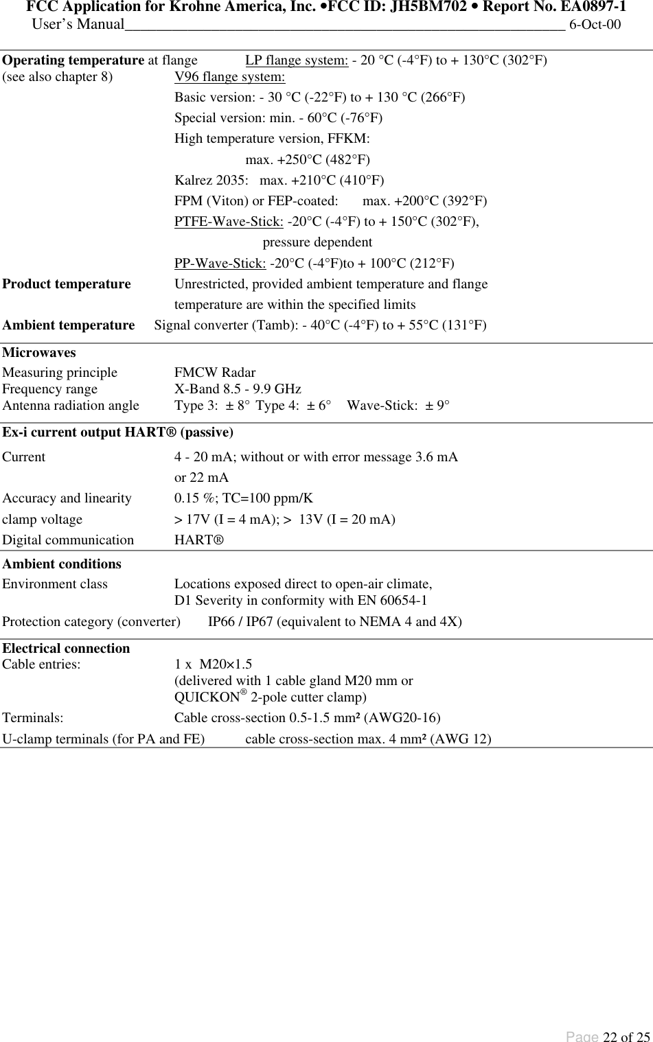
![FCC Application for Krohne America, Inc. ••FCC ID: JH5BM702 •• Report No. EA0897-1User’s Manual________________________________________________________ 6-Oct-00Page 21 of 25Technical data (extract)Tank height (measuring range) 0.5 to 20 m / 1.6 to 65.6 ftMeasuring accuracy (distance) from 1m/3ft: + 1cm/0.4” ; from 5m/16ft: + 0.2%Measured-value resolution 1 mm / 0.04”Rate of change in level max. 10 m/min / 32.8 ft/min (tracking speed)Connecting flangesHorn antenna/Wave-Guide DIN 2501 DN 50 to DN 200 / PN 6 to PN 64 andhigher;Shape C to DIN 2526 or othersANSI B16.5 2” to 8",Class 150 lb or 300 lb, RFWave-Stick Only DN 50...150 or ANSI 2”...6”, dairy DIN11851DN50/65/80, Tri-Clamp 2/3/4”, SMS 51/63/76mm, G 1½"Max. allowable operating pressure -1 bar (vacuum) to max. 64 bar / 928 psig, depending on versionand flange pressure rating. (see name plate)LP flange system with horn antenna, Wave-Guide or Wave-Stick without flange plate-1 bar (vacuum) to +2 bar /29 psigV96 flange system with horn antenna or Wave-Guide:Connection:nominal dia. Flange rated pressurePN 16 PN 25 PN 40 PN 64DN inches bar psig bar psig bar psig bar psig80 3 16 232 --- --- 40 580 64 928100 4 16 232 --- --- 38 551 55 797150 6 16 232 --- --- 34 493 47 681200 8 16 232 25 362 32 464 45 652Wave-Stick: max. 16 bar / 232 psig, temperature-dependent:-20 +150+100-1+1+16 46 - 0.3·T[°C] bartemperature Tpressure+232[psig] [bar]+14-14+212 +302°F745 - 2.42·T[°F] psig](https://usermanual.wiki/KROHNE/BM702.Users-Manual/User-Guide-120815-Page-21.png)