KROHNE FMCW24G74L Level Probing Radar User Manual MA OPTIWAVE7400 24 en 151210 4003518001 R01
KROHNE Level Probing Radar MA OPTIWAVE7400 24 en 151210 4003518001 R01
KROHNE >
Contents
- 1. Manual English
- 2. Manual French
Manual English

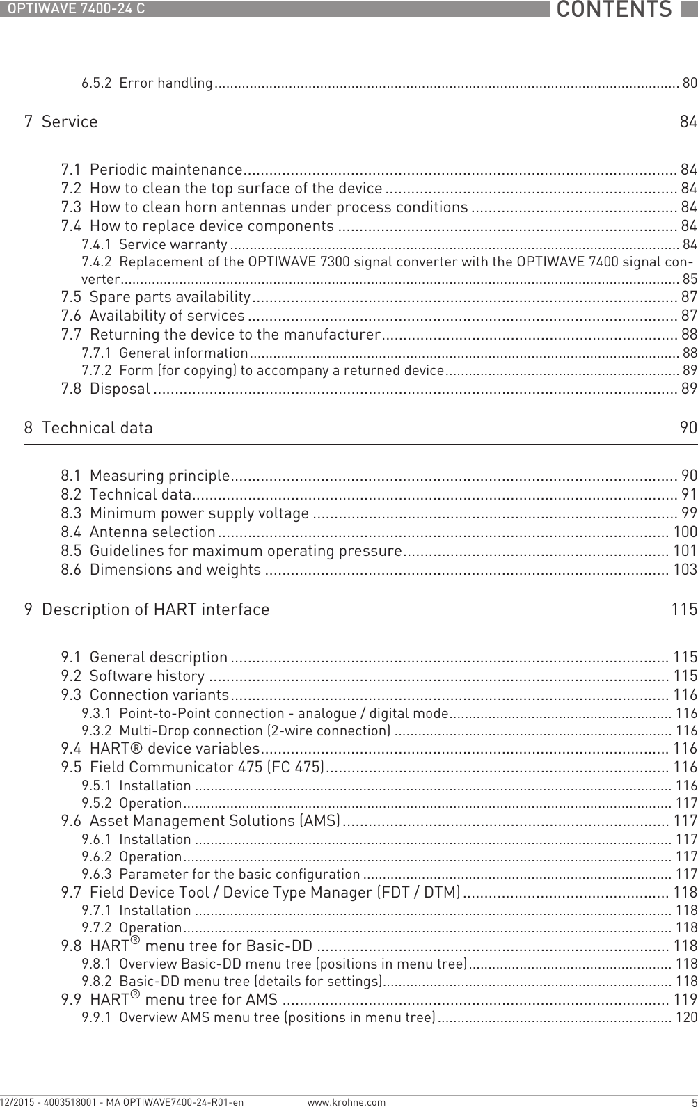
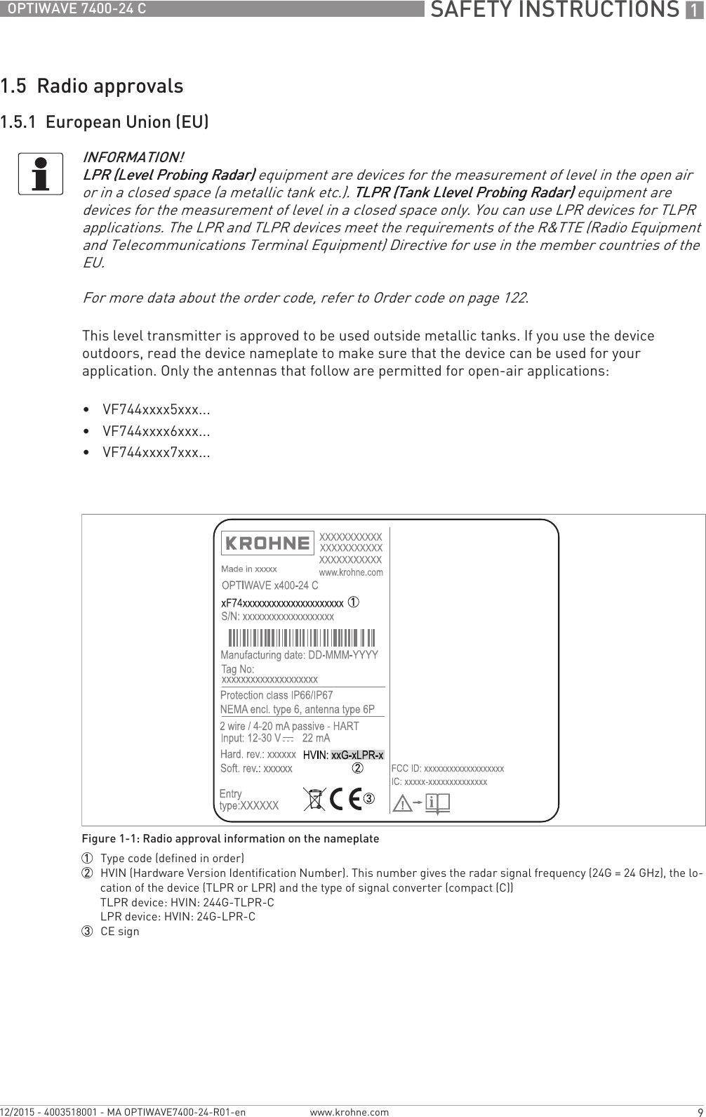
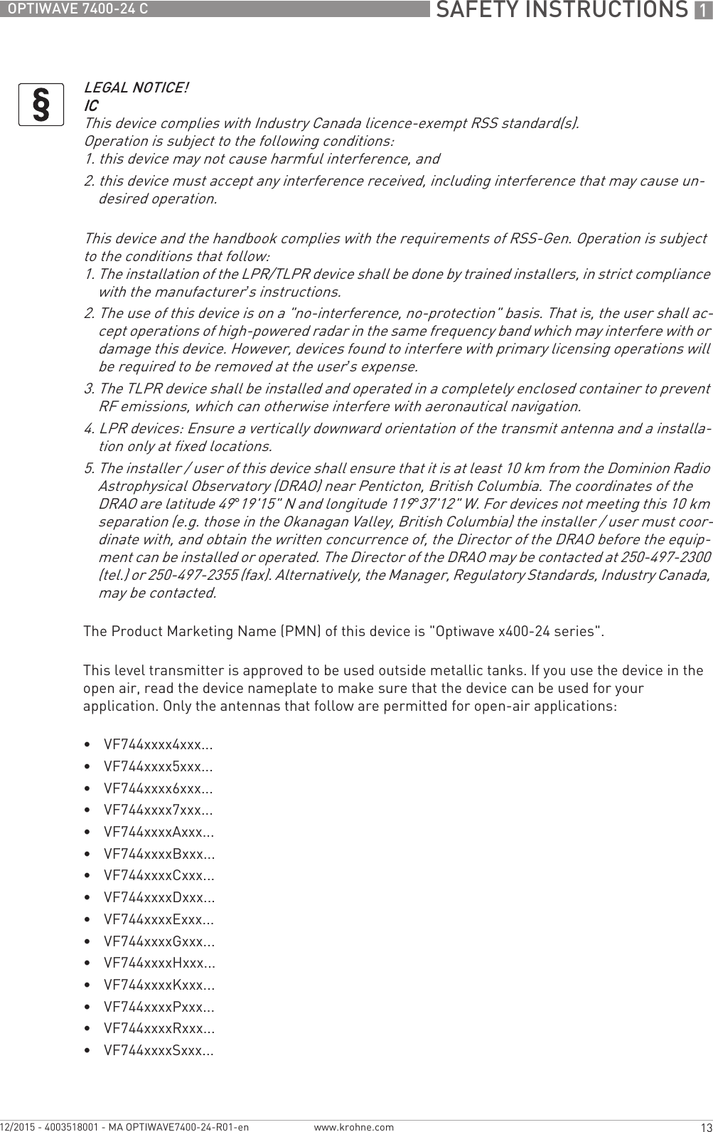
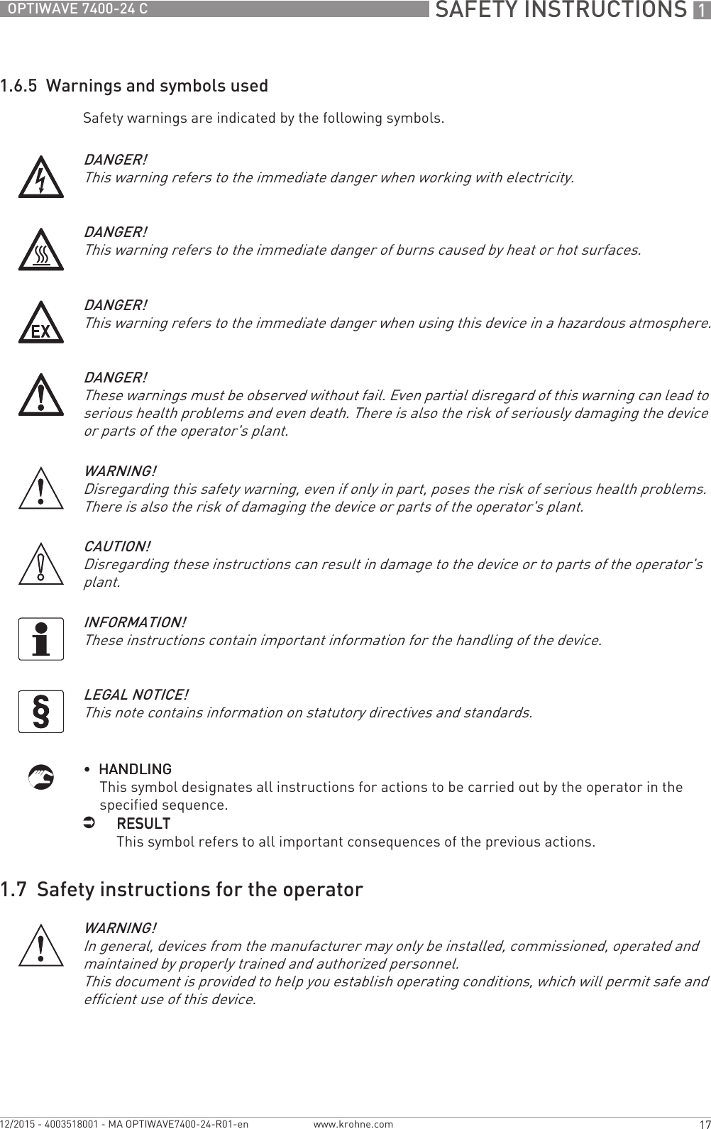
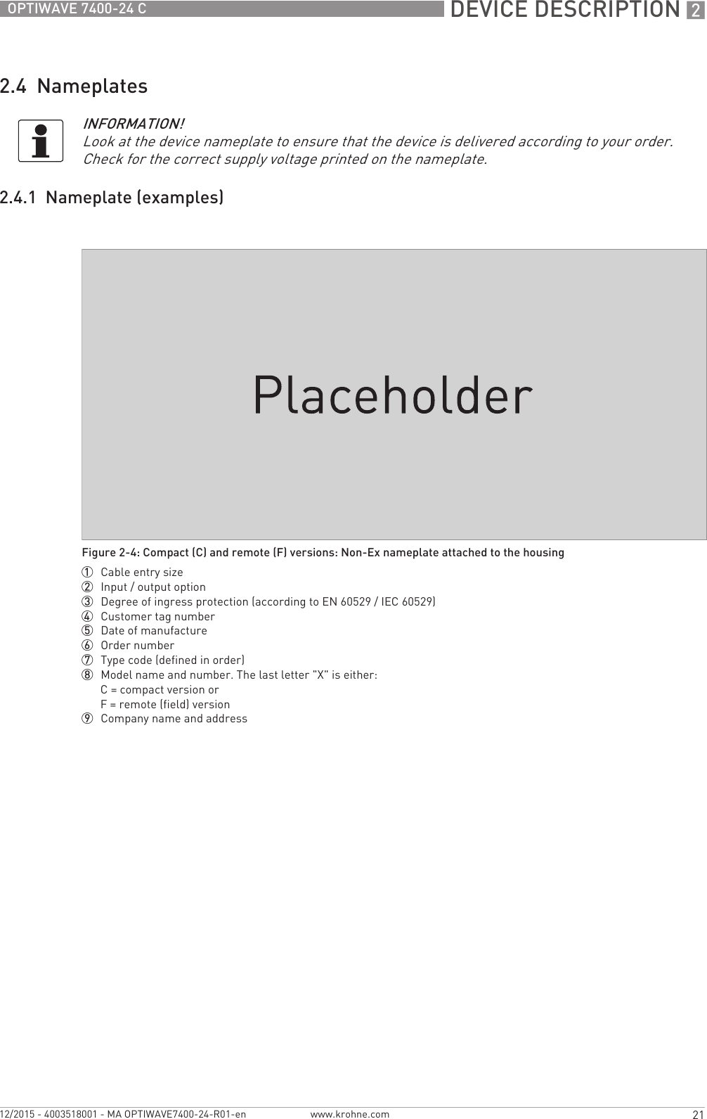
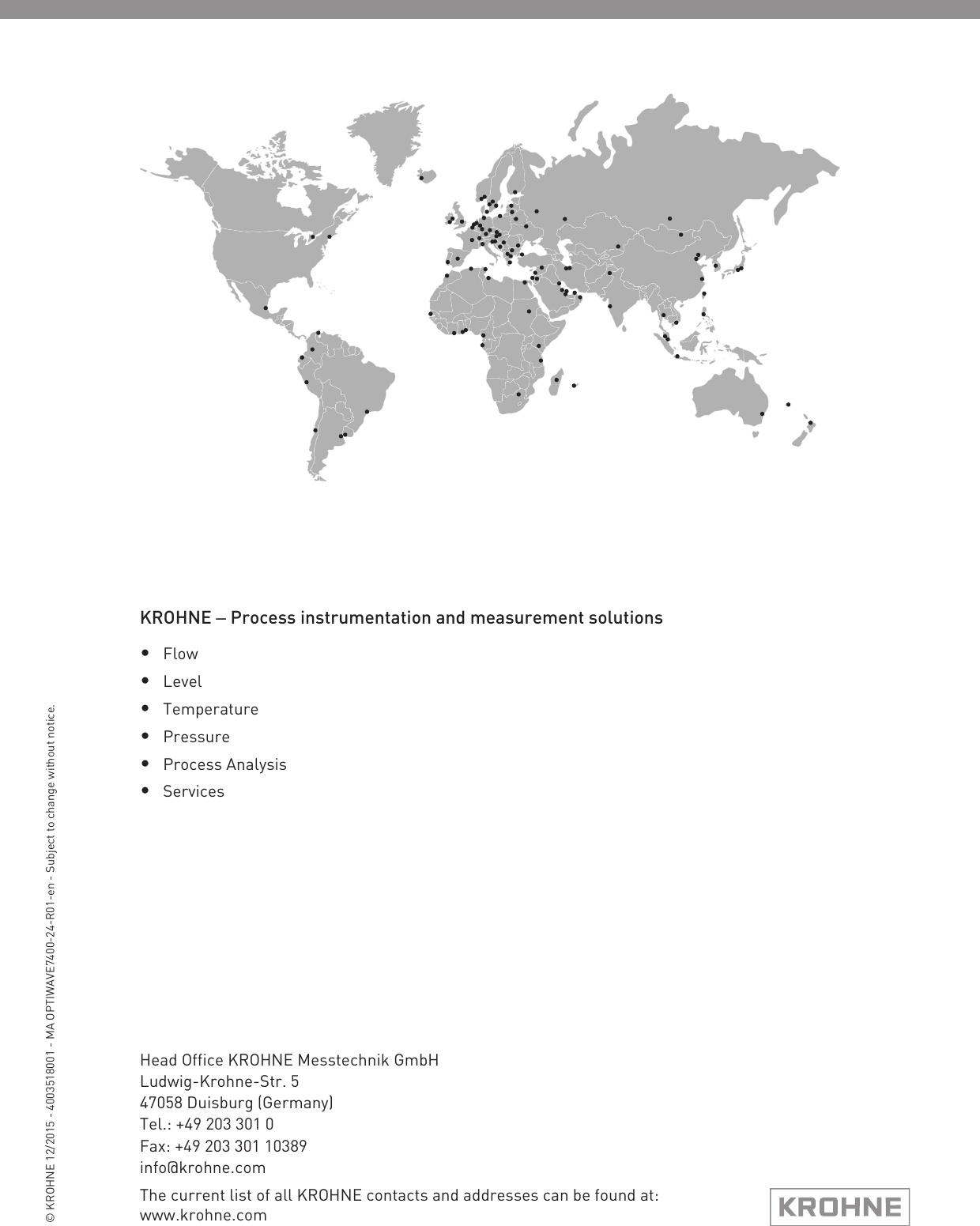
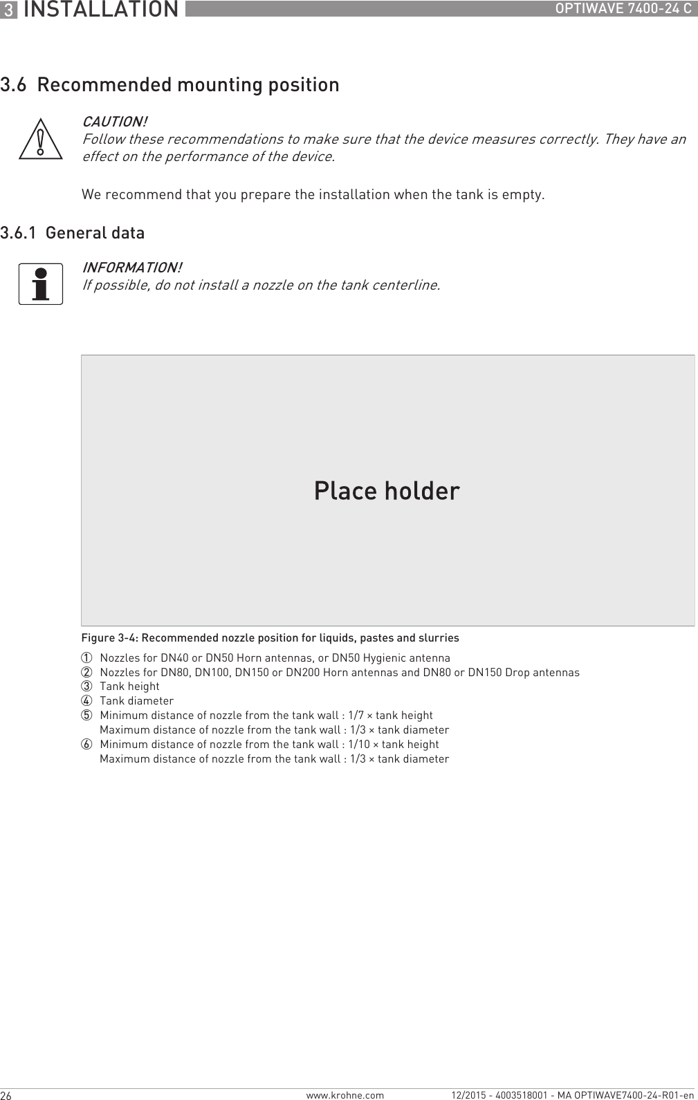
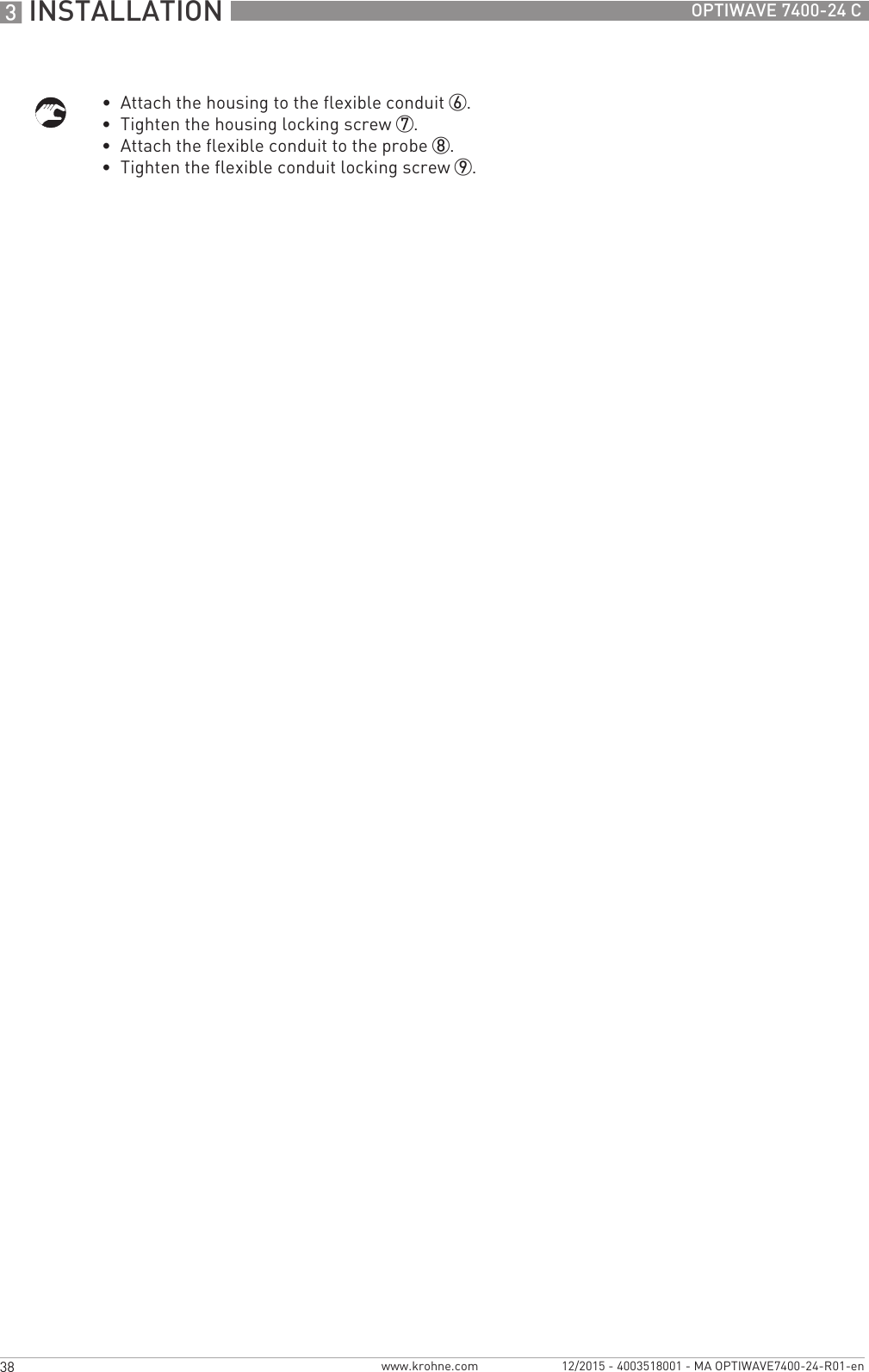
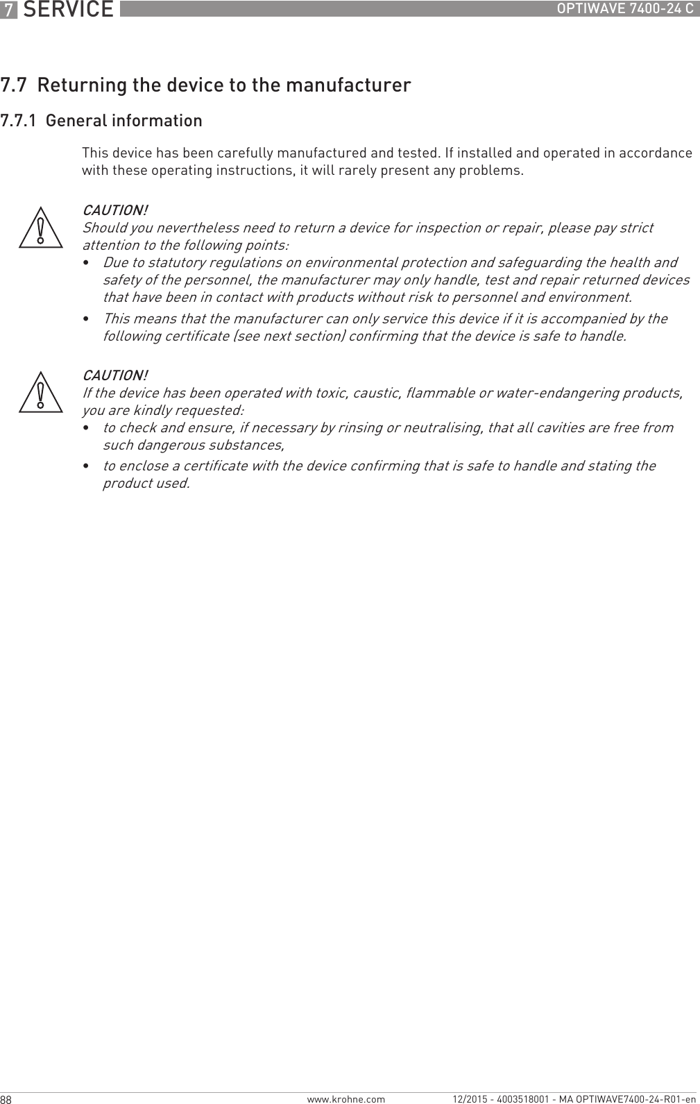
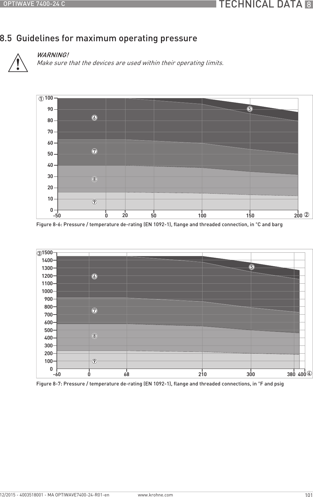
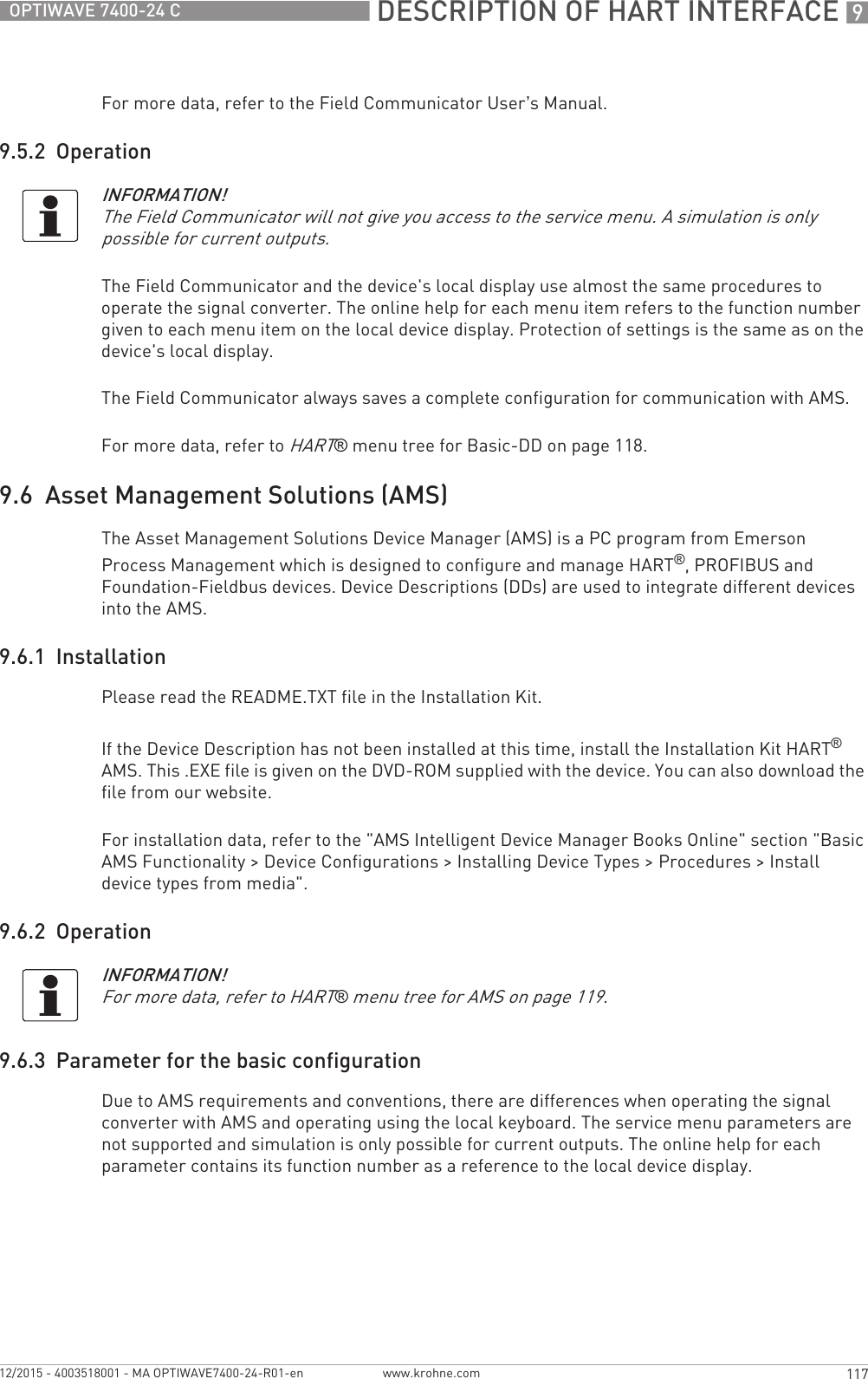
![INSTALLATION 325OPTIWAVE 7400-24 Cwww.krohne.com12/2015 - 4003518001 - MA OPTIWAVE7400-24-R01-en3.5 Pressure and temperature rangesFigure 3-3: Pressure and temperature ranges1 Flange temperatureFKM/FPM gasket: -40...+200°C / -40...+390°F; Kalrez® 6375 gasket: -20...+200°C / -4...+390°F;EPDM gasket: -50...+150°C / -58...+300°FEx devices: see supplementary operating instructions2 Ambient temperature for operation of the display-20...+60°C / -4...+140°FIf the ambient temperature is not between these limits, the display screen switches off automatically3 Ambient temperatureNon-Ex devices: -40...+80°C / -40...+175°FEx devices: see supplementary operating instructionsWARNING!The process connection temperature range must agree with the temperature limits of the gasket material. The operating pressure range is subject to the process connection used and the flange temperature.Antenna type Maximum process connection temperatureMaximum operating pressure[°C] [°F] barg psigPP Drop +100 +210 16 232PTFE Drop +150 +300 40 580PEEK Drop +xxx +xxx xx xxxHygienic +150 +300 10 145Horn / Sheet metal horn +200 1 +300 1 40 (100) 2 580 (1450) 21The maximum process connection temperature must agree with the temperature limits of the gasket material. If the distance piece option is not attached, the maximum process connection temperature is +150°C / +300°F.2Standard operating pressure: 40 barg / 580 psig. Optional max. operating pressure: 100 barg / 1450 psig.](https://usermanual.wiki/KROHNE/FMCW24G74L.Manual-English/User-Guide-2872319-Page-25.png)
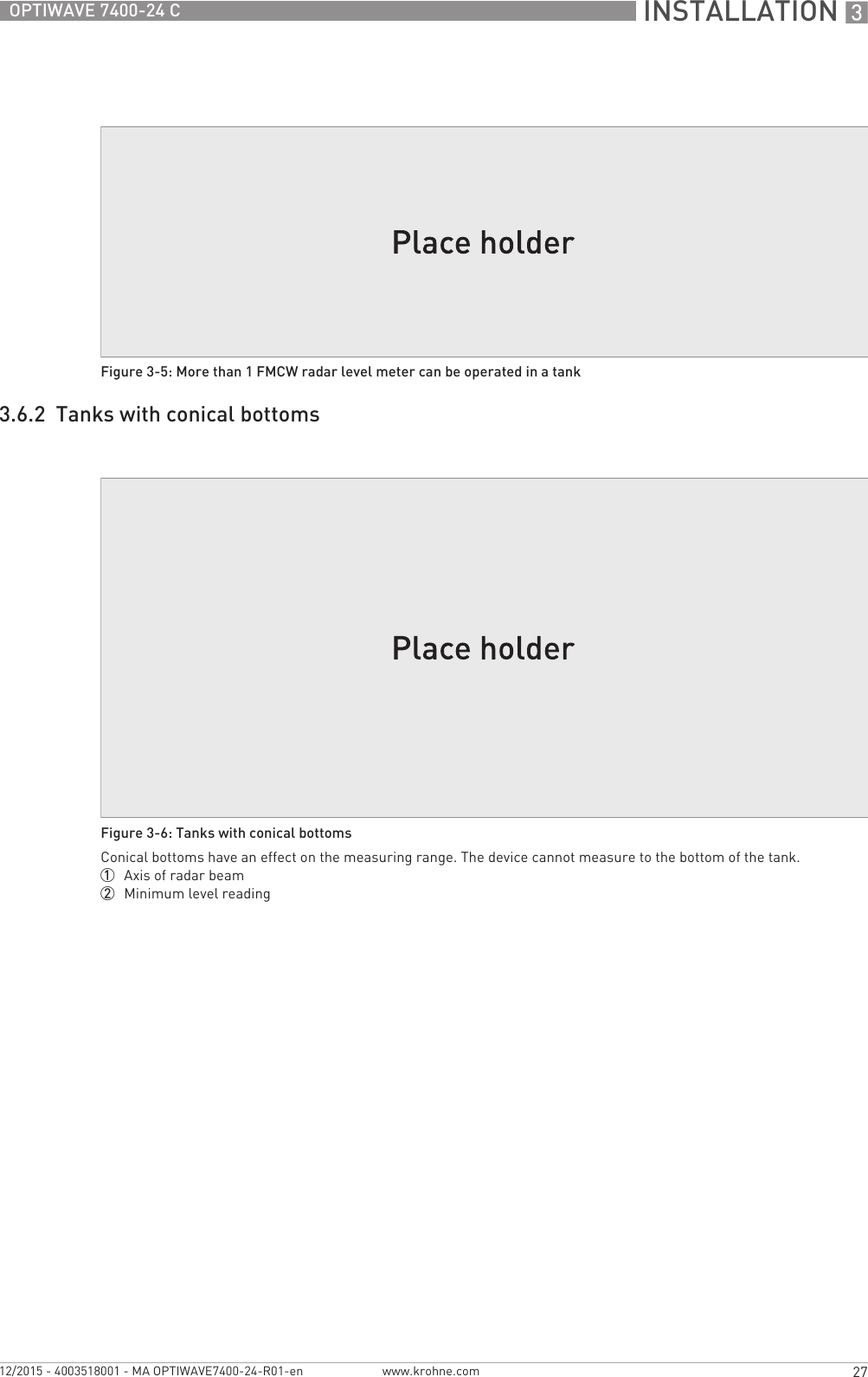
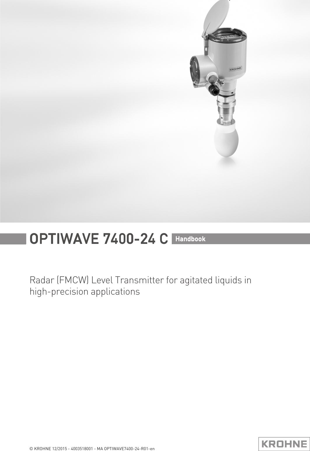
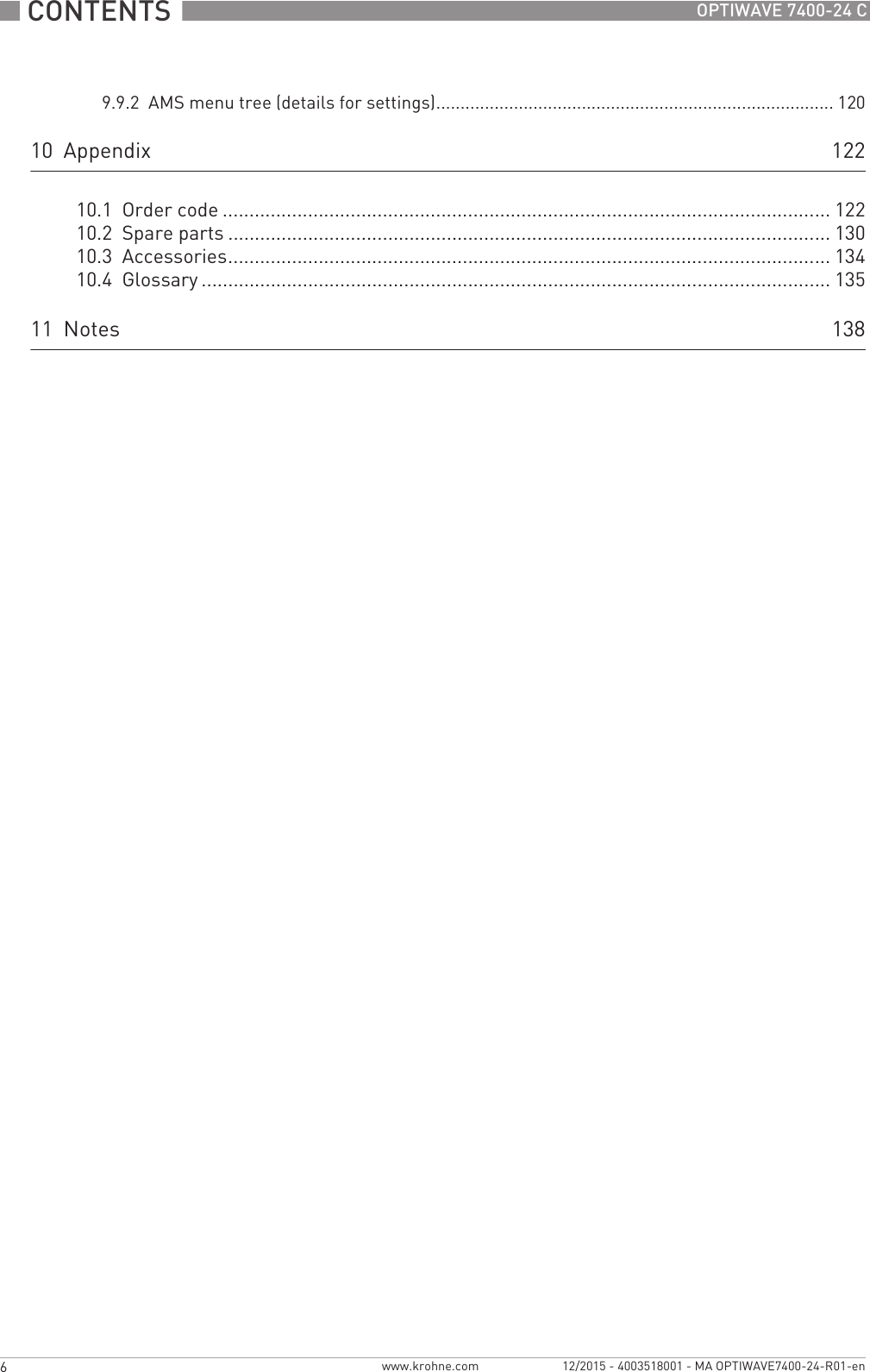
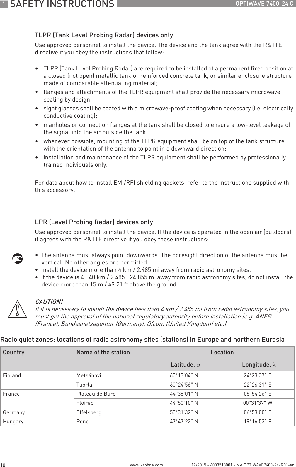
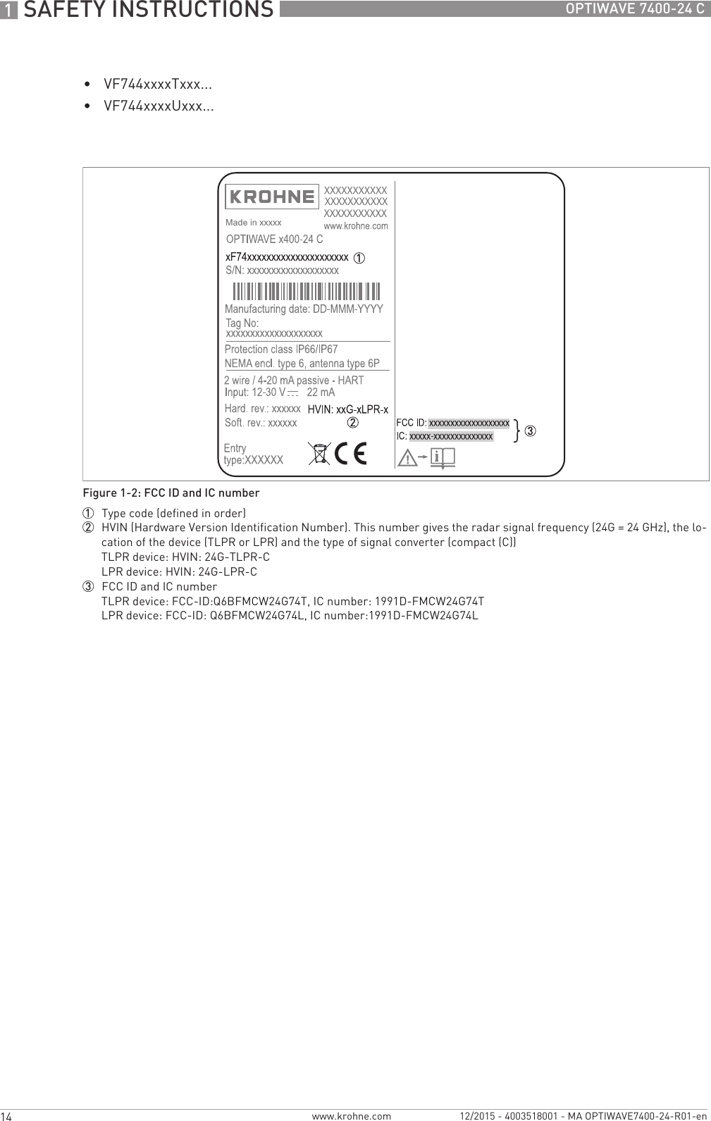
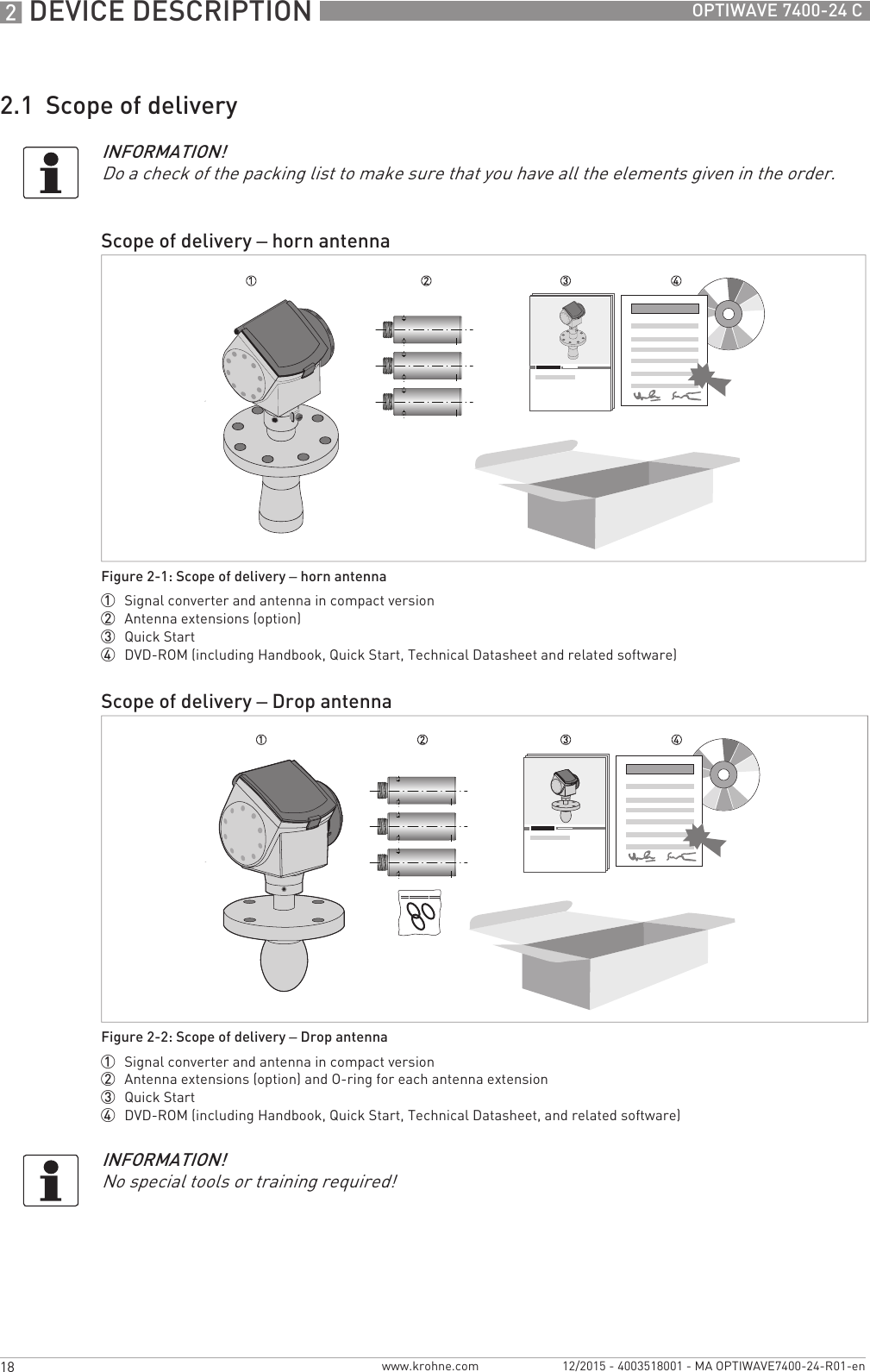
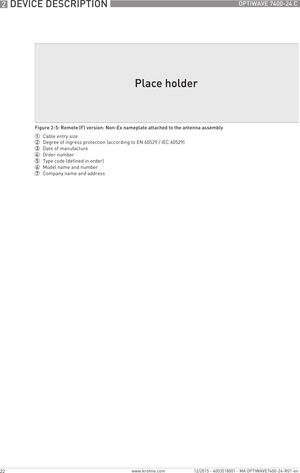
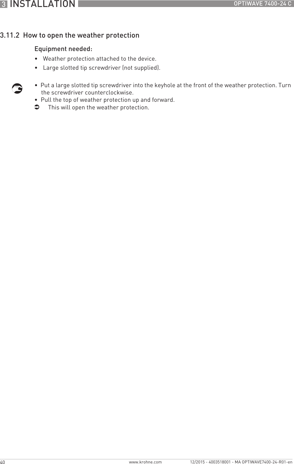
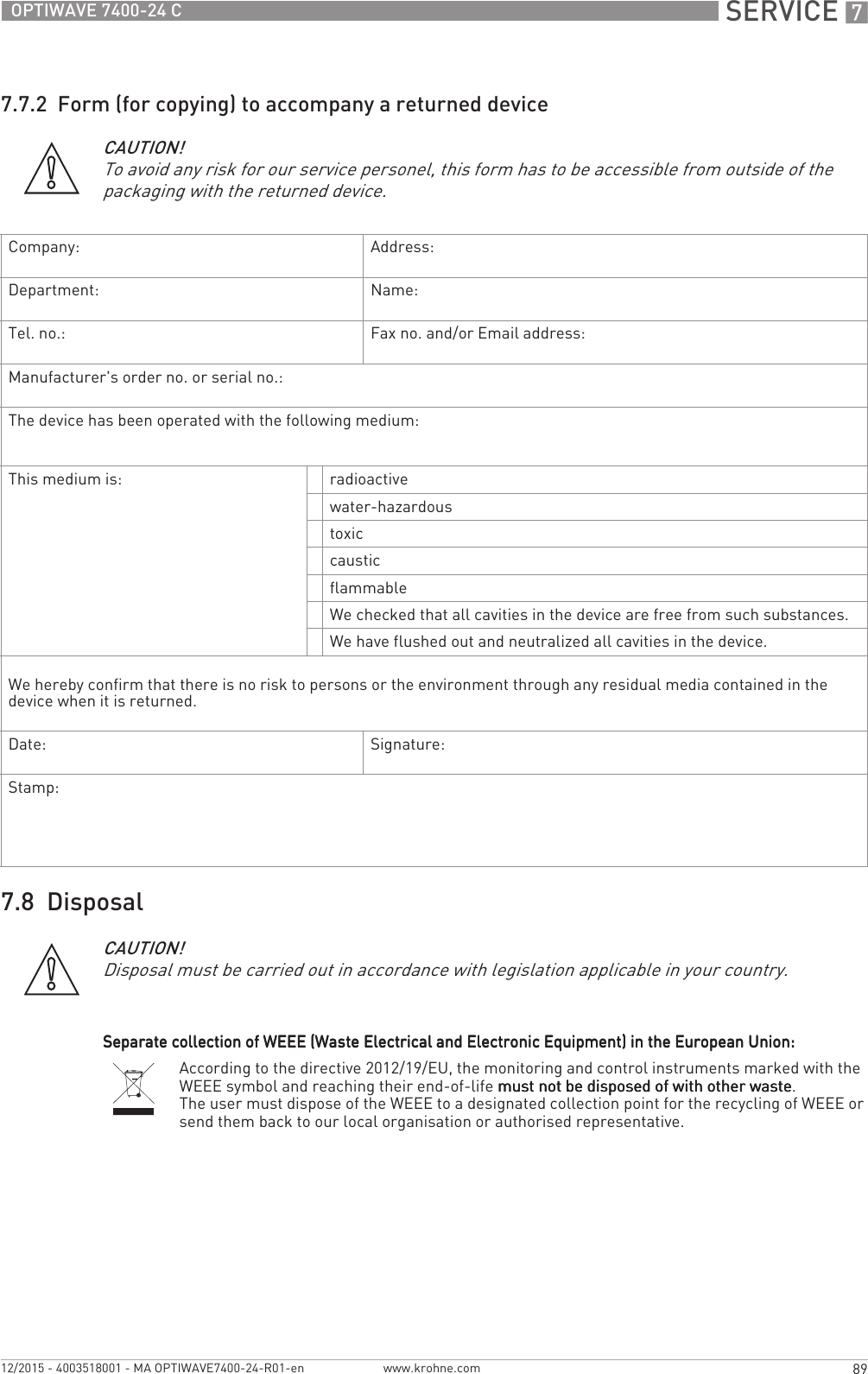
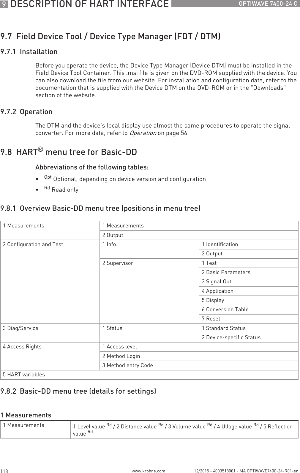
![INSTALLATION 339OPTIWAVE 7400-24 Cwww.krohne.com12/2015 - 4003518001 - MA OPTIWAVE7400-24-R01-enYou can attach the wall bracket of the remote housing to a wall or pipe (DN50...100 / 2¨...4¨). These are the dimensions:Dimensions in mmDimensions in inches3.11 Weather protection3.11.1 How to attach the weather protection to the deviceEquipment needed:•Device.•Weather protection (option).•10 mm wrench (not supplied).The overall dimensions of the weather protection are.• Loosen the bracket nuts on the weather protection.• Remove the bracket.• Lower the weather protection onto the device.• Turn the weather protection so that the keyhole points forward.• Attach the bracket.• Lift the weather protection to the top of the housing support pillar.• Hold the weather protection in the correct position and tighten the bracket nuts.Figure 3-18: Dimensions of the wall bracketDimensions [mm]a b c d e f g h i jWall bracket 120 60 20 11 90 150 667.4 126.4 150.4Dimensions [inches]a b c d e f g h i jWall bracket 4.7 2.4 0.8 0.4 3.5 5.9 0.2 2.65 4.98 5.92](https://usermanual.wiki/KROHNE/FMCW24G74L.Manual-English/User-Guide-2872319-Page-39.png)
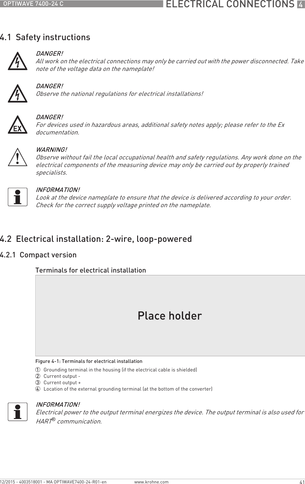
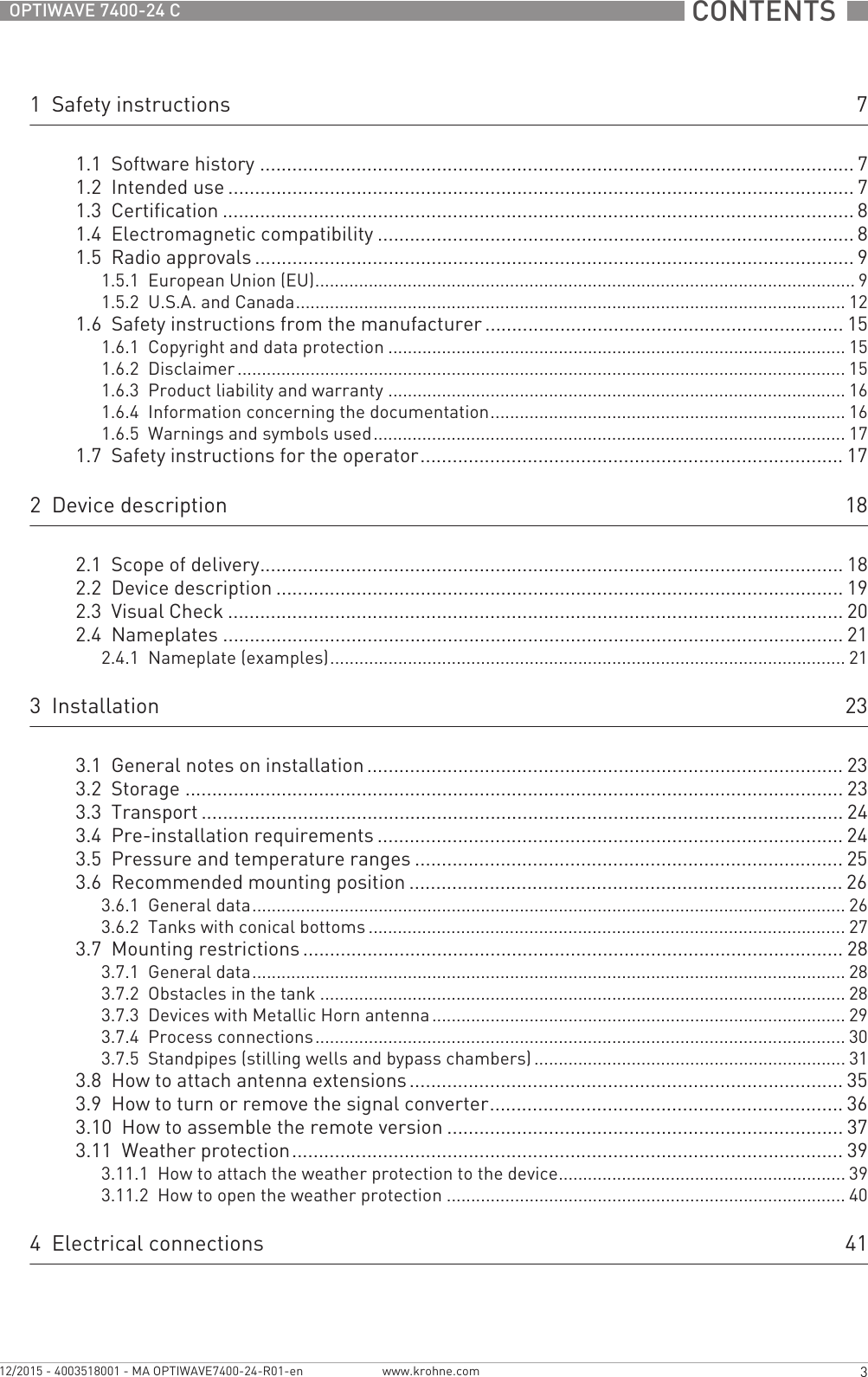
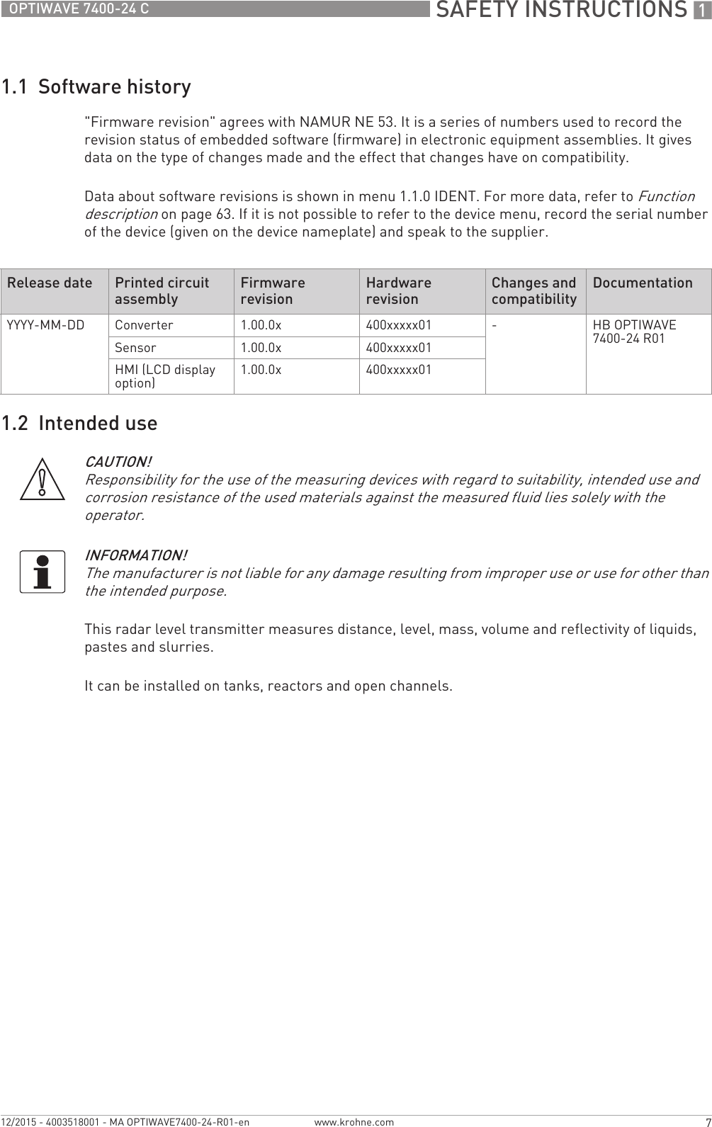
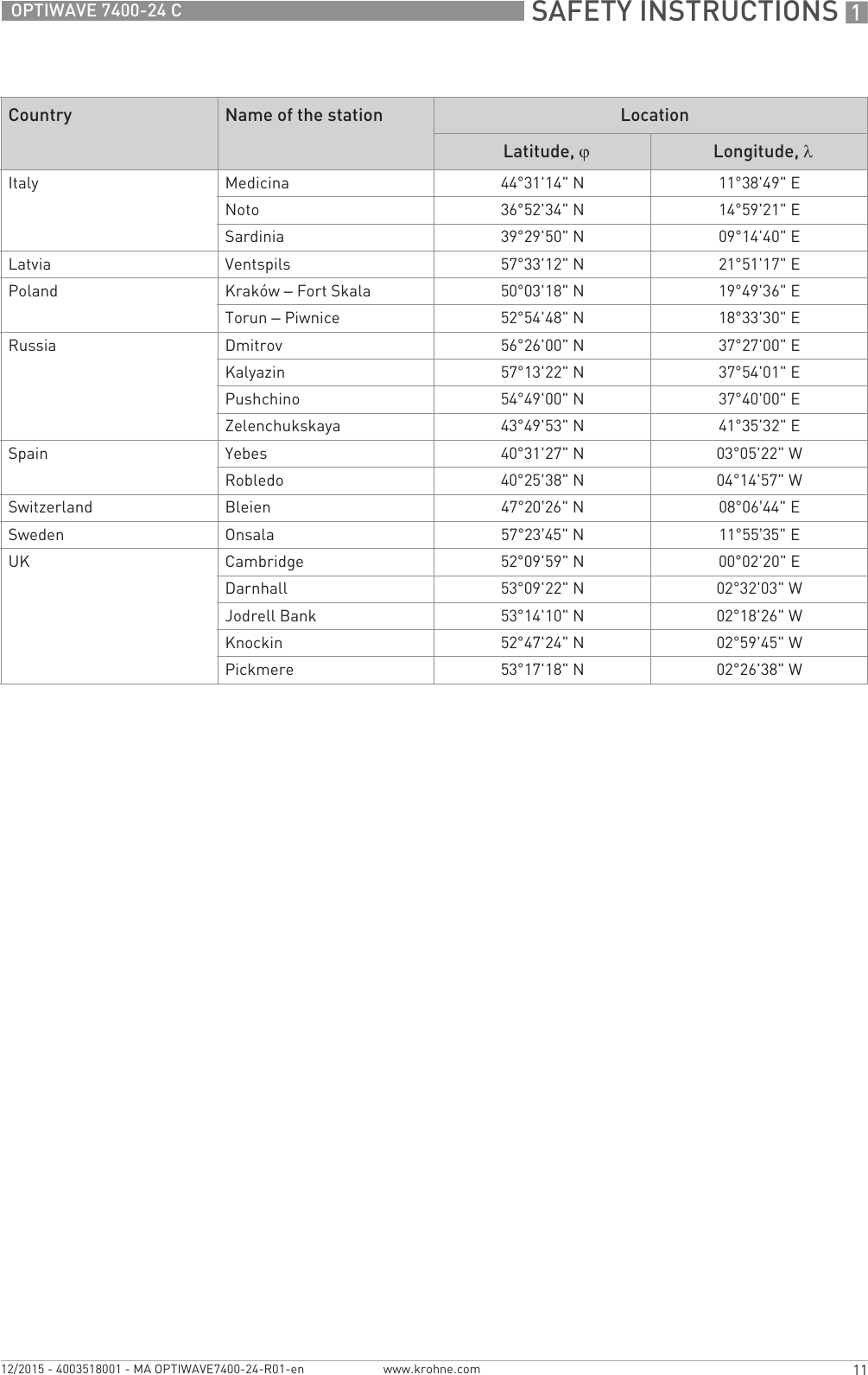
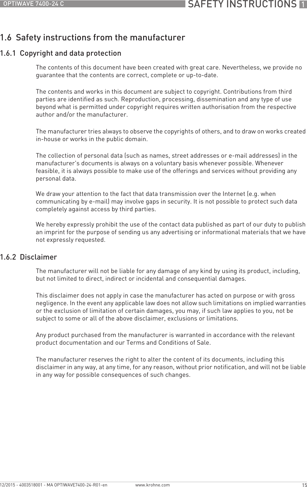
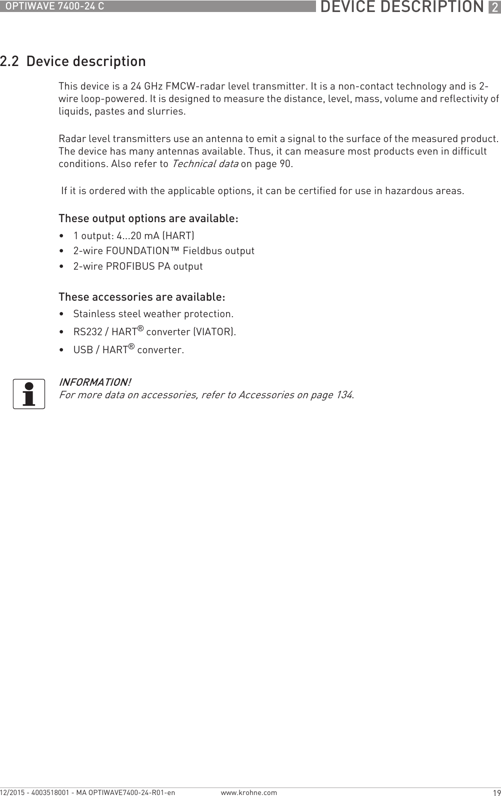
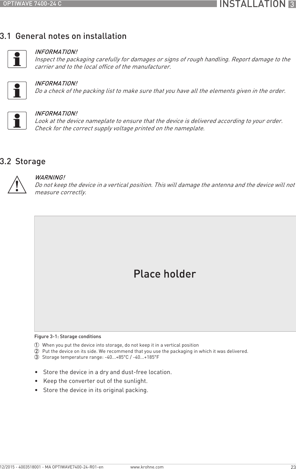
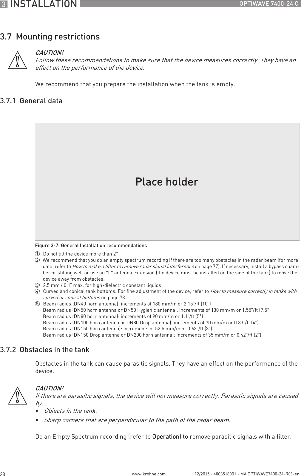
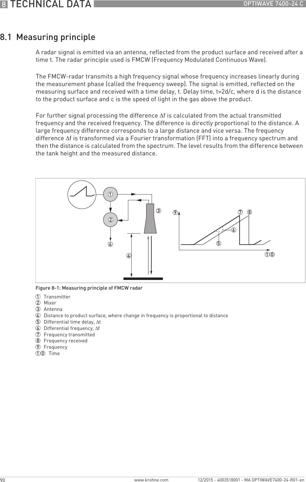
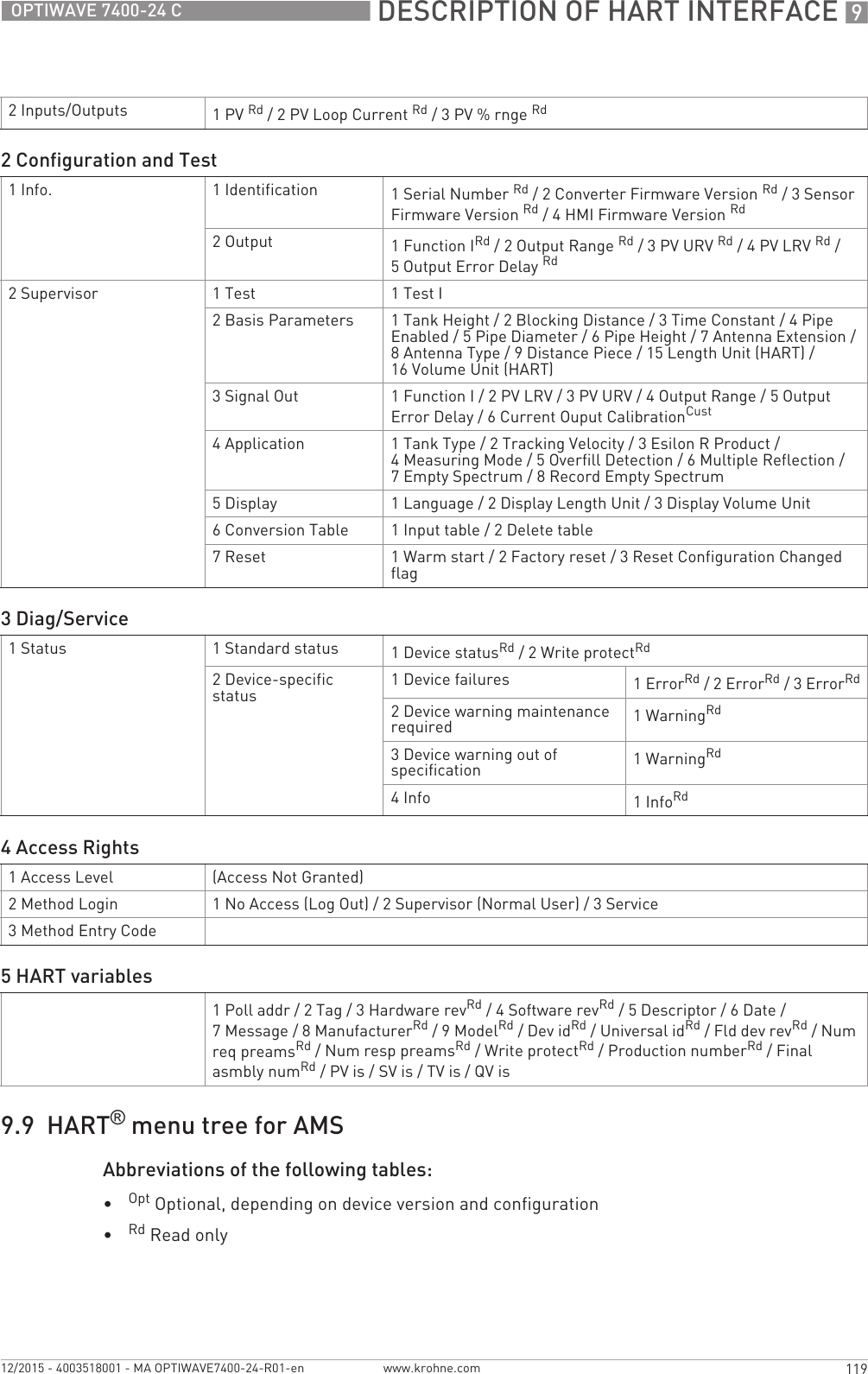
![5 START-UP 54 OPTIWAVE 7400-24 Cwww.krohne.com 12/2015 - 4003518001 - MA OPTIWAVE7400-24-R01-en5.3.2 Functions of keypad buttonsFor data on keypad functions, refer to Normal mode on page 57.5.4 Remote communication with PACTware™PACTware™ displays measurement information clearly on a computer (PC) and lets you configure the device from a remote location. It is an Open Source, open configuration software for all field devices. It uses Field Device Tool (FDT) technology. FDT is a communication standard for sending information between the system and the field device. Field devices are easily integrated. Installation is supported by a user-friendly Wizard.Install these software programs and equipment:•Microsoft® .NET Framework version 1.1 or later.Figure 5-2: Local display screen layout in configuration mode1 Function name2 Configuration mode symbol3 Menu numberKeypad button Function [Right] Normal mode:Normal mode:Normal mode:Normal mode: Enter menu (Enter Configuration mode)Configuration mode:Configuration mode:Configuration mode:Configuration mode: Move cursor to the right [Return / Escape] Normal mode:Normal mode:Normal mode:Normal mode: Change units (m, cm, mm, in, ft)Configuration mode:Configuration mode:Configuration mode:Configuration mode: Exit [Down] Normal mode:Normal mode:Normal mode:Normal mode: Change measurement type (distance, level , output (%), output (mA), conversion, ullage conversion) 1Configuration mode:Configuration mode:Configuration mode:Configuration mode: Decrease value or change parameter [Up] Normal mode:Normal mode:Normal mode:Normal mode: Change measurement type (distance, level , output (%), output (mA), conversion, ullage conversion, reflection) 1Configuration mode:Configuration mode:Configuration mode:Configuration mode: Increase value or change parameter1If you have made a strapping table in menu item 2.8.1 INPUT TABLE for volume or mass measurement, "Conversion" and "Ullage Conv." will be shown in the list of measurement types](https://usermanual.wiki/KROHNE/FMCW24G74L.Manual-English/User-Guide-2872319-Page-54.png)
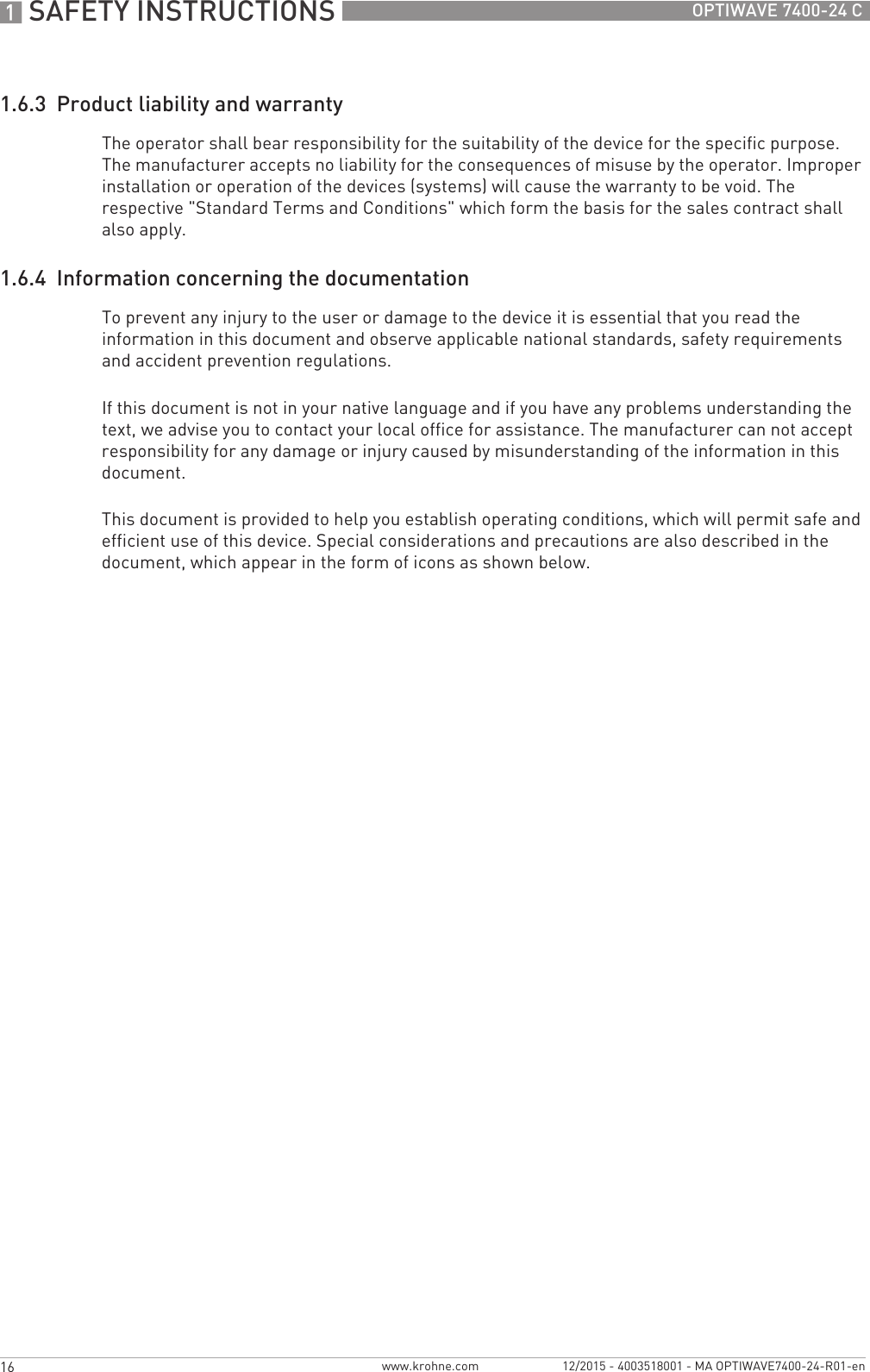
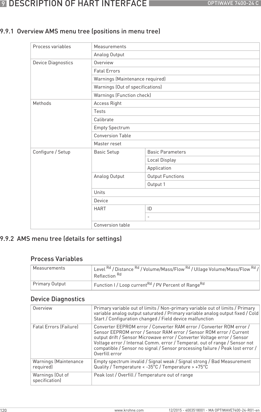
![6 OPERATION 58 OPTIWAVE 7400-24 Cwww.krohne.com 12/2015 - 4003518001 - MA OPTIWAVE7400-24-R01-en6.3 Configuration mode6.3.1 General notesChange the settings of your device in ConfigurationConfigurationConfigurationConfiguration mode. Data about the menus is given on page 63. You can:•Use the 1.0.0 INFORMATION1.0.0 INFORMATION1.0.0 INFORMATION1.0.0 INFORMATION menu to read settings, device software versions and error records. For more data about the Information menu, refer to Table 1: Info.•Use the 2.0.0 SUPERVISOR2.0.0 SUPERVISOR2.0.0 SUPERVISOR2.0.0 SUPERVISOR menu to commission the device, to run diagnostic tests, set up a conversion table for volume, mass or flow rate measurement, change critical parameters for difficult process conditions, reset the device and change basic parameters (tank height etc.), output settings, HART Address etc. For more data about the Supervisor menu, refer to Table 2: Supervisor.6.3.2 How to get access to the commissioning menuThe Quick Setup menu contains the menu items that are necessary for most configurations of the device. The menu items are divided into 2 groups: "Commisioning" and "Recording Empty Spectrum". The "Commisioning" group lets the supervisor set the tank height, tank type (process, storage etc.), output function, output current range, 4 mA output setting, 20 mA output setting, error delay and tag name. "Recording Empty Spectrum" is a procedure that finds interference signals in the tank and uses a filter to remove them from the measurement data.Do the steps that follow:• Push the [>>>>] button.iThis shows the InformationInformationInformationInformation menu. The InformationInformationInformationInformation menu is read only and does not have password security.• Push the [] button one time to scroll up to the SupervisorSupervisorSupervisorSupervisor menu.iThe screen shows the text "2.0.0 SUPERVISOR".• Push the [>>>>] button one time.iThe screen shows a line. You must enter the password. Push the buttons under the display screen 6 times (in total and in a given order) to get access to Configuration mode.• Type in the password. The factory-set password is [>>>>], [^^^^], [], [], [>>>>] and [^^^^].iThe device shows the text "2.1.0 QUICK SETUP".CAUTION!The quick setup (commissioning) procedure is mandatory.INFORMATION!It is not possible to enter the 3.0.0 SERVICE and 4.0.0 MASTER menus. These menus are for factory calibration and approved personnel only.INFORMATION!HOW TO SET THE SUPERVISOR PASSWORD TO "ON" OR "OFF"The supervisor password is set to "on" by default. If it is necessary to set this function to "off", refer to Function description on page 63, Table 2: Supervisor menu, menu item PSWD YES/NO (2.7.4).](https://usermanual.wiki/KROHNE/FMCW24G74L.Manual-English/User-Guide-2872319-Page-58.png)
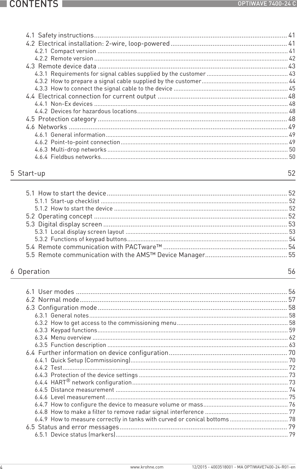
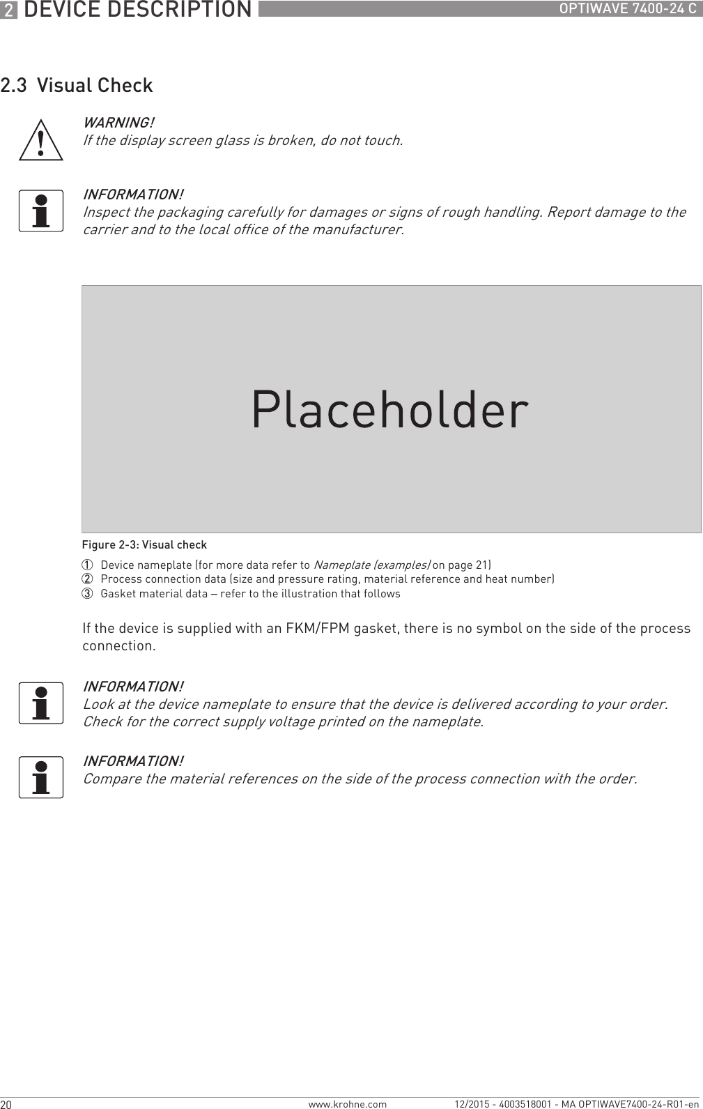
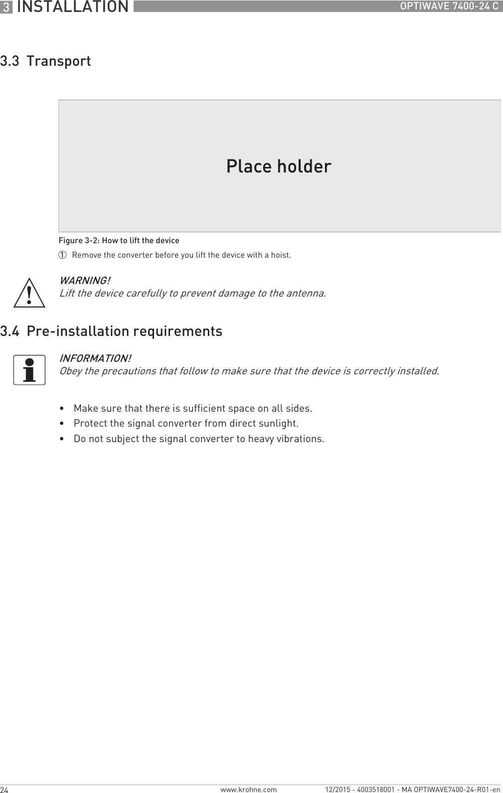
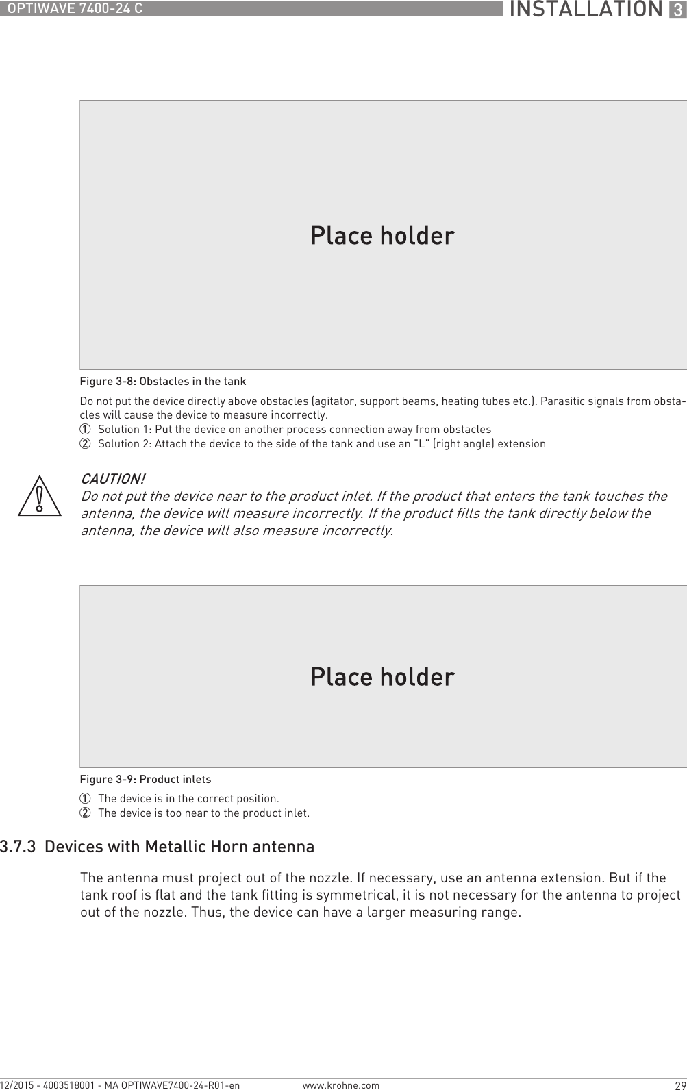
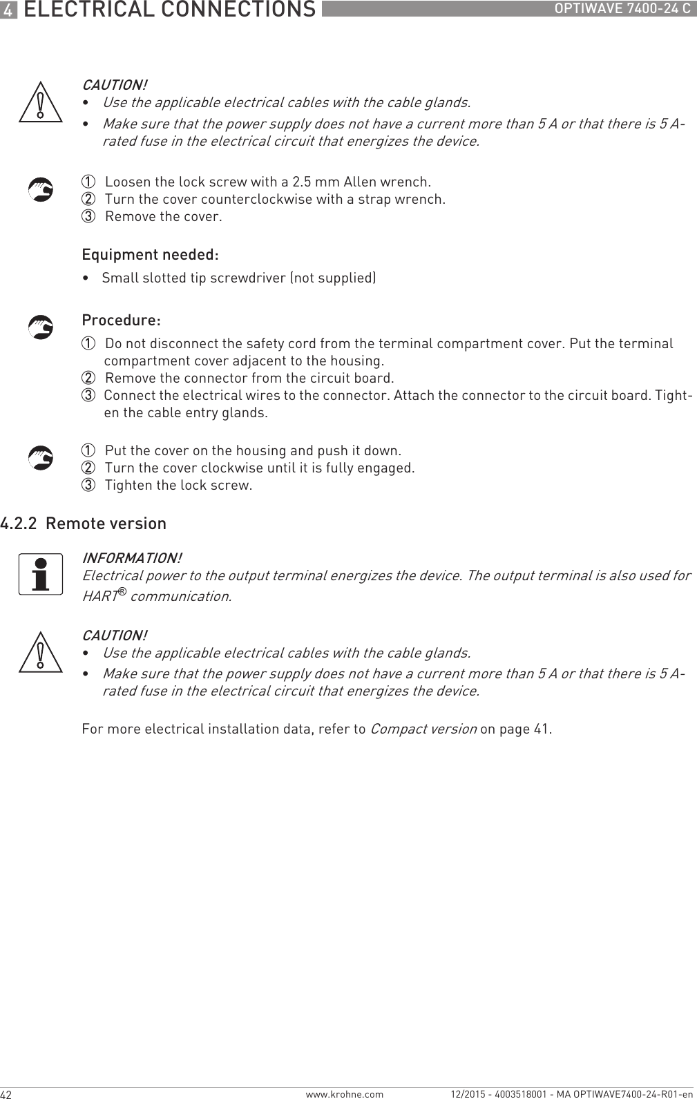
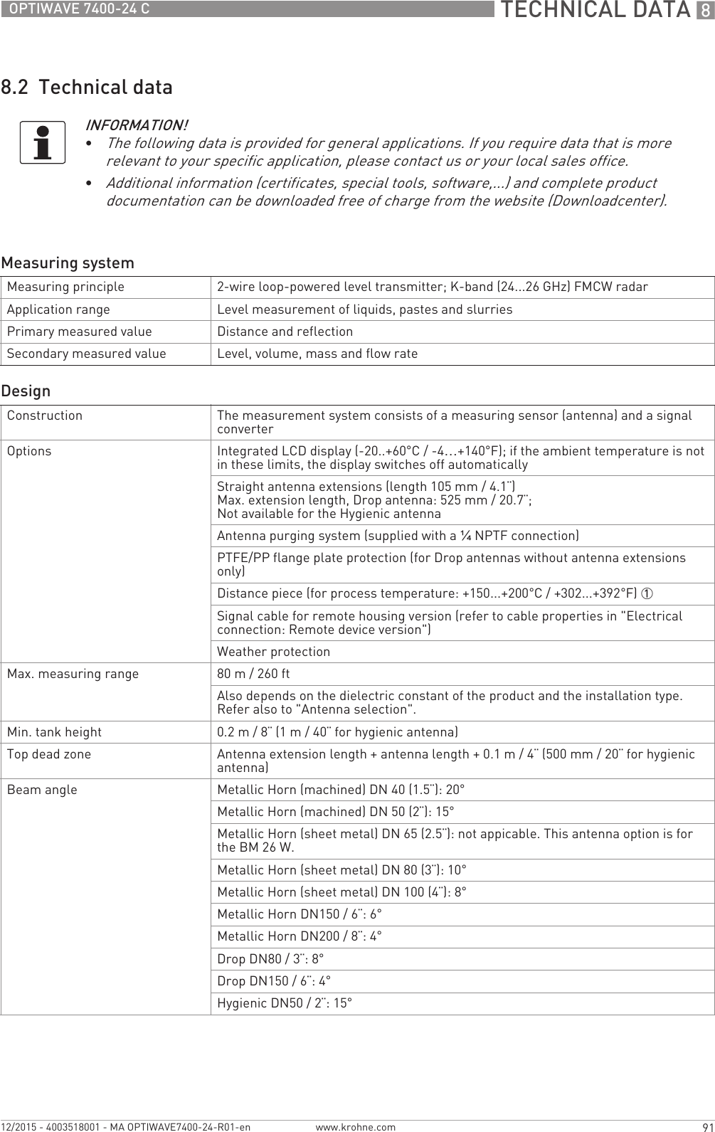
![OPERATION 661OPTIWAVE 7400-24 Cwww.krohne.com12/2015 - 4003518001 - MA OPTIWAVE7400-24-R01-enThis is what you see when you select a menu item that has a value. The functions of the buttons are given in the table that follows:Function of buttons in menu items that have valuesHow to save settings changed in the supervisor menu (menu 2.0.0)• When you have changed parameters in all the necessary menu items, push [^^^^] to accept the new parameter.• Push [^^^^] to go back to the "STORE" screen.• The device will ask you to save or cancel your settings. Push [] or [] to select STORE YESSTORE YESSTORE YESSTORE YES or STORE NOSTORE NOSTORE NOSTORE NO. Push [^^^^] to accept or reject the new settings.iThe display goes back to Normal mode.Values in menu itemsFigure 6-3: Values in menu items1 Menu item with values stored at this time (first screen)2 Push [>>>>] again to change the values. A cursor shows on the first digit.3 Menu item name4 Cursor on the selected digitButton Description FunctionRight•Enter the menu item and see the value stored at this time.•Enter the menu item configuration level to change the value.•Move the cursor to the next digit on the right. If the cursor is on the last digit, push [>>>>] again to go back to the first digit.Enter / Esc (Escape) Accept the value and go back to the sub-menu.Down Decrease the digit value.Up Increase the digit value.](https://usermanual.wiki/KROHNE/FMCW24G74L.Manual-English/User-Guide-2872319-Page-61.png)
![OPERATION 663OPTIWAVE 7400-24 Cwww.krohne.com12/2015 - 4003518001 - MA OPTIWAVE7400-24-R01-en6.3.5 Function description1.0.0 Information (Info.) menuMenu No.Function Function description Selection list Default1.1.0 IDENT.1.1.1 SERIAL NUM. The device serial number. Read only.1.1.2 CONV.FIRM.VER The converter firmware version. Read only.1.1.3 SEN.FIRM.VER The sensor firmware version. Read only.1.1.4 HMI.FIRM.VER The HMI (device display screen) firmware version. Read only.1.1.5 The converter hardware version. Read only.1.1.5 The sensor hardware version. Read only.1.1.8 The HMI (device display screen) hardware version. Read only.1.1.9 The date of manufacture. Read only.1.2.0 OUTPUT1.2.1 OUTPUT FUNC. This shows the setting at this time for the output function (OUTPUT FUNC.). Read only.1.2.2 RANGE I This shows the setting at this time for the output range (RANGE I). Read only.1.2.3 SCALE 4mA This shows the setting at this time for the 4 mA setting (SCALE 4mA). Read only.1.2.4 SCALE 20mA This shows the setting at this time for the 20 mA setting (SCALE 20mA). Read only.1.2.5 ERROR DELAY This shows the settings at this time for the error delay (ERROR DELAY). Read only.1.3.0 HISTORY1.3.1 ERROR RECORD A log of device errors. Push [>>>>] to read the errors. Push [] or [] to scroll up or down the list. Each error is identified by a code. Push [>>>>] again to show the number of incidents and the time since the last incident in days, hours, minutes and seconds. For more data about errors, refer to Status and error messages on page 79.Read only.1.3.2 A log of the last 10 changes to the device settings. Push [] or [] to scroll up or down the list. Push [>>>>] to show the time since the last change in days, hours, minutes and seconds.Read only.](https://usermanual.wiki/KROHNE/FMCW24G74L.Manual-English/User-Guide-2872319-Page-63.png)
![6 OPERATION 64 OPTIWAVE 7400-24 Cwww.krohne.com 12/2015 - 4003518001 - MA OPTIWAVE7400-24-R01-en2.0.0 Supervisor menuMenu No.Function Function description Selection list Default2.1.0 COMMISSION.2.1.1 PARAMETERS This starts a quick set-up procedure applicable to most applications. The supervisor can give the display language (LANGUAGE), tank height (TANK HEIGHT), type of tank (TANK TYPE), output function (OUTPUT FUNC.), current output range (RANGE I), 4 mA setting (SCALE 4mA), 20 mA setting (SCALE 20mA), error delay (ERROR DELAY) and tag name (TAG NAME).2.1.2 EMP.SPEC.REC. Fixed and moving objects in the tank cause interference signals. Put them through this filter to correctly measure the tank contents. A quick set-up procedure will go through the steps that follow (refer also to "How to make a filter to remove radar signal interference" on page 77):1Do you have a completely filled tank?Do you have a completely filled tank?Do you have a completely filled tank?Do you have a completely filled tank?If the tank is full, it is not possible to complete this procedure. The tank must be partially filled or empty.Yes [>>>>], No []2Please, activate moving parts!Please, activate moving parts!Please, activate moving parts!Please, activate moving parts!We recommend that you switch on moving equipment to filter all interference signals.OK [>>>>]3Is your tank partially filled or empty?Is your tank partially filled or empty?Is your tank partially filled or empty?Is your tank partially filled or empty?If the tank is partially filled, the device must include the tank contents when it filters the signal.Partially [>>>>], Empty []4MEAS.DISTANCEMEAS.DISTANCEMEAS.DISTANCEMEAS.DISTANCEIf the tank is partially filled, type in a distance shorter than that between the flange and the tank contents.min-max: 0…tank height (2.3.1) distance to tank contents - 300 mm / 12¨5Emp.Spec.TypeEmp.Spec.TypeEmp.Spec.TypeEmp.Spec.TypeUse the average value for tanks which contain fixed objects only. Use the maximum value for tanks which contain many objects or moving objects.Maximum, Average ?6Recording in progressRecording in progressRecording in progressRecording in progressReading in progressReading in progressReading in progressReading in progress7Empty spectrum graphEmpty spectrum graphEmpty spectrum graphEmpty spectrum graphThis shows a set of spectra (signals found in the tank). It also gives the amplitude and location of each signal. Push [>>>>] to make a selection from the available spectra.8Do you want to save the empty spectrum data? Yes [>>>>], No []2.2.0 TESTS2.2.1 SET OUTPUT This sets the current output to a test value [mA]. The output will change to the given value, independent of the measured value. The current output will go back to the measured value when the display goes back to the menu level.3.5, 4, 6, 8, 10, 12, 14, 16, 18, 20 or 22 mA 3.5 mA](https://usermanual.wiki/KROHNE/FMCW24G74L.Manual-English/User-Guide-2872319-Page-64.png)
![OPERATION 665OPTIWAVE 7400-24 Cwww.krohne.com12/2015 - 4003518001 - MA OPTIWAVE7400-24-R01-en2.2.2 DIAGNOSTIC This starts the hardware test. Push [>>>>] many times to show:•D1, the time of operation•T1, temperature of the electronic converter board•I1, loop current (internally measured value)•I2, load current (NOTE: this data is not available at this time)•V1, voltage 5.6 V. If the voltage is not 5.0<V1<5.7, speak to the supplier.•V2, voltage on capacitors. If the voltage is not 3.2<V2<3.4, speak to the supplier.•V3, voltage 3.3 V. If the voltage is not 3.2<V3<3.4, speak to the supplier.•C1, reset counter (watchdog timer). If C1>1, replace the signal converter.If an NE 107 symbol and a status marker are shown, refer to Device status (markers) on page 79.If you push [>>>>] again, the display goes back to the menu level.2.2.3. The corrected spectrum. TBD.2.3.0 BASIC PARAM.2.3.1 TANK HEIGHT The distance from the flange face / thread stop of the tank connection down to the tank bottom. If the tank has a dish-shaped or conical bottom, the tank height is measured to a point on the tank bottom directly below the antenna. For more data about level measurement, refer to Level measurement on page 75. For more data about distance measurement, refer to Distance measurement on page 74.min-max: 0…30 m / 0…98.4 ft12.3.2 BLOCK. DIST. Blocking distance. The distance from the flange to the top limit of the measuring range (a zone given by the user where it is not possible to measure). We recommend a blocking distance of 500 mm / 19.7¨ below the process connection. We also recommend that the limit of the measuring range is not less than the blocking distance. If it is possible that the tank contents will go above the blocking distance, set 2.5.5 OVERF. ENAB. to "Yes". If the distance is less than the blocking distance, the device continues to display the blocking distance.min: 100 mm / 13.9¨ or 2.3.6 ANTENNA.EXTmax: 2.3.1 TANK HEIGHT500 mm / 19.7¨2.3.3 TIME CONST. Using this function, the device processes several measurement readings to filter out disturbances. Increasing the time constant will smoothen the integrated readings, decreasing will roughen the readings. s=seconds.min-max: 1.00...100.00 s 5.00 s2.3.4 TAG NAME The device has an identification code (tag name). The supervisor can enter a maximum of 8 numbers or letters.12.3.5 ANTENNA.EXT Optional antenna extensions.These are attached between the flange and the antenna.min: 0 mm / 0¨ or 2.3.6 ANTENNA.EXTmax: 2000 mm / 78.7¨ or 2.3.1 TANK HEIGHT1Menu No.Function Function description Selection list Default](https://usermanual.wiki/KROHNE/FMCW24G74L.Manual-English/User-Guide-2872319-Page-65.png)
![6 OPERATION 68 OPTIWAVE 7400-24 Cwww.krohne.com 12/2015 - 4003518001 - MA OPTIWAVE7400-24-R01-en2.5.8 MULT.REF.EN. Multiple reflections will cause the device to display smaller level readings. Objects in the tank, sharp corners, installation of the device on a large nozzle or at the centre of a dome roof, and low dielectric products (εr= 1.8...5) can cause multiple reflections. A very calm surface or a tank with a small convex or flat roof can also cause multiple reflections.If this function is in operation, the device looks for the first signal peak below the process connection. This signal peak is then used to measure the level of the tank contents. If this function is not in operation, the device looks for the largest signal below the process connection.YES, NO NO2.5.7 EMP.SPEC.EN. The supervisor can start or stop the empty spectrum filter. YES, NO NO2.6.0 COMMUNICAT.2.6.1 ADDRESS Any HART® address greater than 0 will activate HART® multidrop mode. The current output stays constant at 4 mA.min.-max: 0…63 02.6.2 Each HART value (PV (primary value), SV (secondary value), TV (tertiary value) and QV (quaternary value)) can be set to a different measurement type (level, distance, reflectivity, conversion, ullage conversion).2.7.0 DISPLAY2.7.1 LANGUAGE Data can be shown in any of the languages stored in the device. 9 languages are available in 3 packs: (1) English, French, German and Italian; (2) English, French, Spanish and Portuguese; (3) English, Chinese (Mandarin), Japanese and Russian32.7.2 LENGTH UNIT The length unit shown in normal mode. m, cm, mm, in (inches), ft (feet) m2.7.3 CONV UNIT Conversion unit. The length, volume, mass or flow rate conversion unit for the conversion table and shown in normal mode.m3, L, gal (US gallons), ImpG (Imperial gallons), ft3, bbl (oil barrel), kg, t, Ston, Lton, m, cm, mm, in, ft, m3/h, ft3/hL2.7.4 PSWD YES/NO If it is necessary to protect your settings in the supervisor menu with a password, set this menu item to YESYESYESYES.YES, NO YES2.7.5 PASSWORD This changes the password for the supervisor menu. Push the buttons up to 6 times in any order. This will be the new password. To confirm the change, enter the new password a second time. For more data, refer to Protection of the device settings on page 73.[>>>>], [^^^^], [], [], [>>>>] and [^^^^]2.7.6 CONTRAST The contrast control for the display screen. You can select a shade of grey between light grey (level 20) and black (level 54).min.-max: 20…54 36Menu No.Function Function description Selection list Default](https://usermanual.wiki/KROHNE/FMCW24G74L.Manual-English/User-Guide-2872319-Page-68.png)
![OPERATION 669OPTIWAVE 7400-24 Cwww.krohne.com12/2015 - 4003518001 - MA OPTIWAVE7400-24-R01-en3. Service menu4. Master menu2.7.7 If it is not easy to read the data on the LCD display screen, this menu item operates the display screen light. If you set this menu item to YESYESYESYES, the light comes on.YES, NO NO2.8.0 CONV. TABLE2.8.1 INPUT TABLE The device uses a conversion table (strapping table) to convert measurements to volume, mass and flow rate readings. The readings are shown in normal mode. Give the number of entries on the table (min. 2; max. 30). Select an entry (01...30) and enter the level and the related volume / mass / flow rate value for that entry. Push [^^^^] to confirm the entry values. Continue the procedure until the device has data for all the entries. For more data, refer to How to configure the device to measure volume or mass on page 76.min. 2 entriesmax. 30 entries(level / volume, mass or flow rate)0 entries2.8.2 DELETE TABLE This menu item erases the data in the conversion table. YES, NO NO2.9.0 CONFIG/RESET2.9.1 SAVE This menu item is not available. YES, NO NO2.9.2 RECALL This menu item is not available. YES, NO NO2.9.3 RESTART This menu item starts the device again. YES, NO NO2.9.4 RESET FACT. If you set this menu item to "YES", the device goes back to its initial settings (set by the manufacturer in the factory).YES, NO NO1This value is given in the customer order data2Units and range depend on the output function, length unit and volume unit selected3If the device has the LCD display option, this depends on data given in the customer orderMenu No.Function Function description Selection list Default3.0.0 SERVICE Advanced settings. The settings in this menu are protected with a password. Only approved personnel can change the parameters in this menu. For more data, speak or write to your local sales office.Menu No.Function Function description Selection list Default4.0.0 MASTER Factory settings. The settings in this menu are protected with a password. Only approved personnel can change the parameters in this menu. For more data, speak or write to your local sales office.Menu No.Function Function description Selection list Default](https://usermanual.wiki/KROHNE/FMCW24G74L.Manual-English/User-Guide-2872319-Page-69.png)
![6 OPERATION 70 OPTIWAVE 7400-24 Cwww.krohne.com 12/2015 - 4003518001 - MA OPTIWAVE7400-24-R01-en6.4 Further information on device configuration6.4.1 Quick Setup (Commissioning)Use this procedure to change the tank height, tank type, output function, output range and give the top and bottom measuring limits. Values and parameters that can be changed are shown between the «... » marks in the illustrations that follow. Push the keypad buttons in the correct sequence:ProcedureCAUTION!Make sure that you do this procedure before you use the device. The settings in this procedure have an effect on the performance of the device.Screen Steps Description•[>>>>], [] and [>>>>]. Default screen.Enter configuration mode (2.0.0 SUPERVISOR).•[>>>>], [^^^^], [], [], [>>>>] and [^^^^]. Enter the password (the default password is shown). If it is necessary to change the password, menu item 2.7.5 PASSWORD.•2× [>>>>] Push this button to start the quick set-up procedure.•[>>>>] to change the tank height (H).•[>>>>] to change the position of the cursor.•[] to decrease the value or [] to increase the value.•[^^^^] to confirm.The distance from the flange face / thread stop of the tank connection down to the tank bottom. If the tank has a dish-shaped or conical bottom, the tank height is measured to a point on the tank bottom directly below the antenna.•[] or [] for the selection of the conditions in which the device is used (Storage, Process, Agitator).•[^^^^] to confirm.If the surface of the product is flat, select "Storage". If the surface of the product is disturbed, select "Process". If the surface of the product is agitated with vortexes and foam, select "Agitator".](https://usermanual.wiki/KROHNE/FMCW24G74L.Manual-English/User-Guide-2872319-Page-70.png)
![OPERATION 671OPTIWAVE 7400-24 Cwww.krohne.com12/2015 - 4003518001 - MA OPTIWAVE7400-24-R01-en•[] or [] for the selection of the measurement name (Distance, Level, Conversion, Ullage Conv. or Reflection).•[^^^^] to confirm.The manufacturer sets the output function to “Level” before delivery.If it is necessary to measure volume, ullage volume, mass or ullage mass (Conversion or Ullage Conv.), refer to How to configure the device to measure volume or mass on page 76.•[] or [] for the selection of the current output range (4-20 mA/3.6E, 4-20, 3.8-20.5/3.6E, etc.).•[^^^^] to confirm.•[>>>>] to change Scale 4 mA.•[>>>>] to change the position of the cursor.•[] to decrease the value or [] to increase the value.•[^^^^] to confirm.Use this step to give the 4 mA output setting (0% limit) in the tank. Refer to the illustrations that follow. Illustration 1 shows the settings for level. Illustration 2 shows the settings for distance.•[>>>>] to change Scale 20 mA.•[>>>>] to change the position of the cursor.•[] to decrease the value or [] to increase the value.•[^^^^] to confirm.Use this step to give the 20 mA output setting (100% limit) in the tank. Refer to the illustrations that follow. Illustration 1 shows the settings for level. Illustration 2 shows the settings for distance.•[] or [] for the selection of the error delay (0 s, 10 s, 20 s, 30 s, 1 mn, 2 mn, 5 mn or 15 mn).•[^^^^] to confirm.The time after which the current output changes to an error value. The error value shows that there is a measurement error.Screen Steps Description](https://usermanual.wiki/KROHNE/FMCW24G74L.Manual-English/User-Guide-2872319-Page-71.png)
![6 OPERATION 72 OPTIWAVE 7400-24 Cwww.krohne.com 12/2015 - 4003518001 - MA OPTIWAVE7400-24-R01-en6.4.2 TestUse this procedure to test the loop current. Values and parameters that can be changed are shown between the «... » marks in the illustrations that follow. Push the keypad buttons in the correct sequence:Procedure•[>>>>] to change the tag name.•[>>>>] to change the position of the cursor.•[] to decrease the alphanumeric value (A, B, ..., 1, 2, ...) or [] to increase the alphanumeric value.•[^^^^] to confirm.The device has an identification code (tag name). The supervisor can enter a maximum of 8 numbers or letters.•2× [^^^^] to confirm.•[] or [] for the selection of the save option (STORE NO or STORE YES).•[^^^^] to confirm.Set to STORE YES to save and use the data. Set to STORE NO to cancel the changes to the device settings.Screen Steps DescriptionScreen Step DescriptionDefault screen.•[>>>>], [] and [>>>>].•Enter the password: [>>>>], [^^^^], [], [], [>>>>] and [^^^^].•[^^^^]•[].•[>>>>].](https://usermanual.wiki/KROHNE/FMCW24G74L.Manual-English/User-Guide-2872319-Page-72.png)
![OPERATION 673OPTIWAVE 7400-24 Cwww.krohne.com12/2015 - 4003518001 - MA OPTIWAVE7400-24-R01-en6.4.3 Protection of the device settingsThe menu item PASSWORD (2.7.5) lets you change the supervisor menu password.How to change the supervisor menu password• After you enter the supervisor menu, push 6 × [], [>>>>] and 4 × [] to go to the menu item PASSWORD (2.7.5).• Enter the new 6-character password (push the 4 buttons in any sequence).• Enter the new 6-character password again.iIf the second entry is the same as the first, the device will go back to the sub-menu list (2.7).If the second entry is not the same as the first, the device will not go back to the sub-menu list. Push [^^^^] to start the password sequence again and enter the new 6-character password 2 times.• Push [^^^^] to go back to the "STORE" screen.• Push [] or [] to set the screen to STORE YESSTORE YESSTORE YESSTORE YES and push [^^^^].iThe device will save the new password and go back to normal mode.How to set the supervisor password to "on" or "off"The supervisor password is set to "on" by default. If it is necessary to set this function to "off" refer to Function description on page 63, Table 2: Supervisor menu, menu item PSWD YES/NO (2.7.4).6.4.4 HART® network configurationThe device uses HART® communication to send information to HART®-compatible equipment. It can operate in either point-to-point or multidrop mode. The device will communicate in multidrop mode if you change the address.•[>>>>].•[] to decrease the value or [] to increase the value.•[^^^^] to confirm.This step sets the loop current value. Make a selection from 3.5, 4, 6, 8, 10, 12, 14, 16, 18, 20 or 22 mA.•[^^^^] 3 times to go back to the default screen.The loop current goes back to initial value.Default screen.Screen Step DescriptionINFORMATION!Make a note of the password and keep it in a safe place. If you lose the password, please speak or write to your supplier.INFORMATION!For more data, refer to Networks on page 49.](https://usermanual.wiki/KROHNE/FMCW24G74L.Manual-English/User-Guide-2872319-Page-73.png)
![6 OPERATION 74 OPTIWAVE 7400-24 Cwww.krohne.com 12/2015 - 4003518001 - MA OPTIWAVE7400-24-R01-enHow to change from point-to-point to multidrop mode• Enter the supervisor menu.• Push [>>>>], 5 × [] and [>>>>] to go to menu item ADDRESS (2.6.1).• Push [>>>>] to change the value. Enter a value between 1 and and push [^^^^] to confirm (refer to the caution before this procedure).• Push [^^^^] to go back to the "STORE" screen.• Push [] or [] to set the screen to STORE YESSTORE YESSTORE YESSTORE YES and push [^^^^].iThe output is set to multidrop mode. The current output is set to 4 mA. This value does not change in multidrop mode.How to change from multidrop to point-to-point mode• Enter the supervisor menu.• Push [>>>>], 5 × [] and [>>>>] to go to menu item ADDRESS (2.6.1).• Push [>>>>] to change the value. Enter the value 0 and push [^^^^] to confirm.• Push [^^^^] to go back to the "STORE" screen.• Push [] or [] to set the screen to STORE YESSTORE YESSTORE YESSTORE YES and push [^^^^].iThe output is set to point-to-point mode. The current output changes to a range of 4...20 mA or 3.8...20.5 mA (this range is set in menu item RANGE I (2.4.2)).6.4.5 Distance measurementThe device displays distance measurements when the output function is set to "Distance". Menu items related to distance measurement are:•Output Function (2.4.1)•Tank Height (2.3.1)•Blocking Distance (2.3.2)Use the flange facing as the reference point for the 4 and 20 mA current output settings. The 4 and 20 mA current output settings are the minimum and maximum points of the measurement scale.You can change the reference point from which distance is measured. Use this menu item:•Reference Offset (2.3.7)CAUTION!Make sure that the address for this device is different from others in the multidrop network.INFORMATION!If you move the reference point above the flange, add this value when you give a distance for the 4 and 20 mA current output settings. If you move the reference point below the flange, subtract this value when you give a distance for the 4 and 20 mA current output settings.CAUTION!If the distance for 4 mA is set in the blocking distance, the device will not be able to use the full current output range.](https://usermanual.wiki/KROHNE/FMCW24G74L.Manual-English/User-Guide-2872319-Page-74.png)
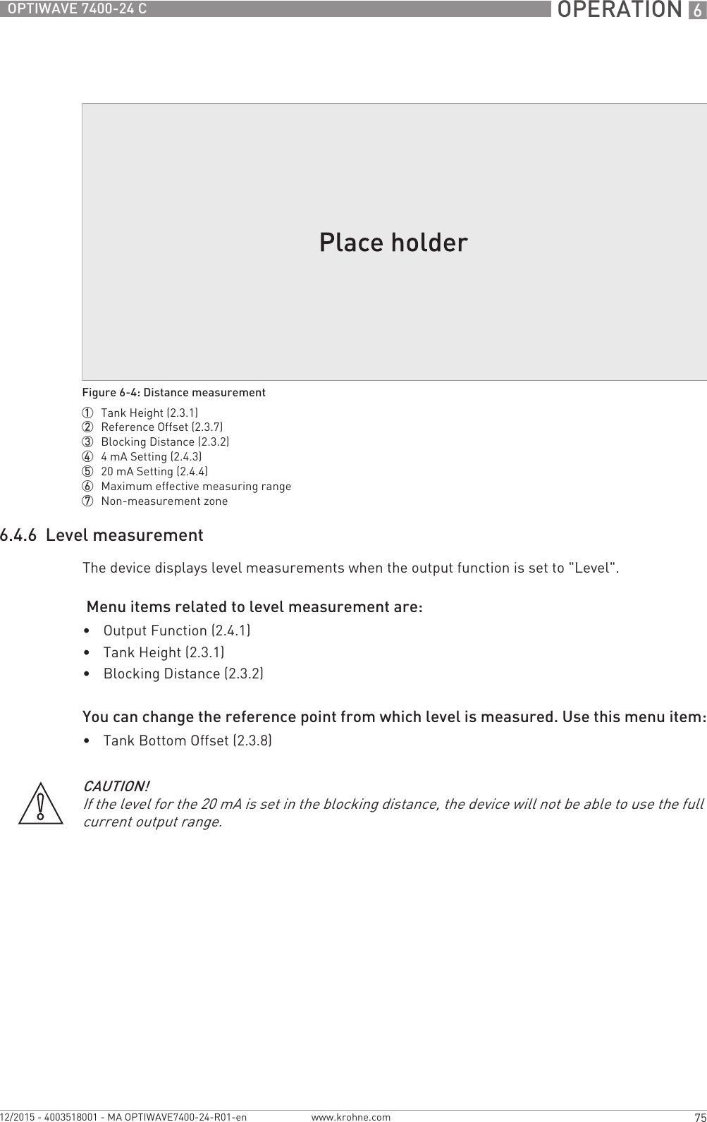
![6 OPERATION 76 OPTIWAVE 7400-24 Cwww.krohne.com 12/2015 - 4003518001 - MA OPTIWAVE7400-24-R01-en6.4.7 How to configure the device to measure volume or massThe device can be configured to measure volume or mass. You can set up a strapping table in the conversion table (2.8.0 CONV. TAB) sub-menu. Each entry is a pair of data (level – volume, level – mass or level – flow rate). The strapping table must have a minimum of 2 entries and a maximum of 30. The reference point for the table is the bottom of the tank (as given in menu item 2.3.1 TANK HEIGHT).How to prepare a strapping table (conversion table)• Enter the supervisor menu.• Push [>>>>], 6 × [], [>>>>] and [] to go to 2.7.2 LENGTH UNIT.• Push [] and [] to find the length unit that you will use in the table.• Push [^^^^] to go to the sub-menu level.• Push [] to go to 2.7.3 CONV UNIT (conversion unit)• Push [] and [] to find the conversion unit that you will use in the table.• Push [^^^^] to go to the sub-menu level and then [] and [>>>>] to go to the menu item 2.8.1 INPUT TAB• Push [>>>>] to make the strapping table. Enter the table entry number (01).• Enter the length value and push [^^^^].• Enter the conversion value and push [^^^^].• Push [>>>>] to enter the subsequent table entry number (02, 03, ..., 30).• Repeat the last 3 steps to complete the table.• Push [^^^^] to go back to the "STORE" screen.• Push [] or [] to set the screen to STORE YESSTORE YESSTORE YESSTORE YES and push [^^^^].Figure 6-5: Level measurement1 Tank Bottom Offset (2.3.8)2 Tank Height (2.3.1)3 Blocking Distance (2.3.2)4 Maximum effective measuring range5 20 mA Setting (2.4.4)6 4mA Setting (2.4.3)7 Non-measurement zoneCAUTION!Enter the data in numerical sequence (strapping table entry number 01, 02 etc.).](https://usermanual.wiki/KROHNE/FMCW24G74L.Manual-English/User-Guide-2872319-Page-76.png)
![OPERATION 677OPTIWAVE 7400-24 Cwww.krohne.com12/2015 - 4003518001 - MA OPTIWAVE7400-24-R01-eniThe device will store the data for the strapping table and go back to normal mode.The device will give more accurate volume readings if you give more conversion data in these areas:•Surfaces with curves.•Sudden changes in the cross section. Refer also to the illustration that follows:How to delete a volume or mass table• Enter the supervisor menu.• Push 7 × [], [>>>>], and [] to go to 2.8.2 DELETE TABLE.• Push [>>>>] and [] to set the parameter to YESYESYESYES.• Push [^^^^] to go back to the "STORE" screen.• Push [] or [] to set the screen to STORE YESSTORE YESSTORE YESSTORE YES and push [^^^^].iThe device will delete the data for the strapping table and go back to normal mode. The "CONVERSION" and "ULLAGE CONV." data are not available in normal mode.6.4.8 How to make a filter to remove radar signal interferenceIf the device measures level in a tank that contains obstructions (agitator, supports, heating pipes etc.), these objects can cause radar signal interference (parasitic signals). You can use the empty spectrum function (menu item 2.1.2) in the Quick Setup menu to make a filter to remove radar signal interference.Figure 6-6: A plot of points for a volume or mass table1 2](https://usermanual.wiki/KROHNE/FMCW24G74L.Manual-English/User-Guide-2872319-Page-77.png)
![6 OPERATION 78 OPTIWAVE 7400-24 Cwww.krohne.com 12/2015 - 4003518001 - MA OPTIWAVE7400-24-R01-en6.4.9 How to measure correctly in tanks with curved or conical bottomsYou can offset the tank bottom reference point to find the delayed radar reflection. Obey the instructions that follow:• • Increase the tank height in menu C.1.2.• Go to the signal screensignal screensignal screensignal screen in operator mode.iYou will see a graph of reflections.• Push [>>>>] to move the cursor to the reflection with the largest amplitude (given in dB).• Make a note of the distance of the reflection measured by the device.iThe distance to the reflection will be the new tank height.• Subtract the distance to the reflection from the true tank height.• Go to Supervisor > Advanced Setup > Installation Setup > Tank Bottom OffsetSupervisor > Advanced Setup > Installation Setup > Tank Bottom OffsetSupervisor > Advanced Setup > Installation Setup > Tank Bottom OffsetSupervisor > Advanced Setup > Installation Setup > Tank Bottom Offset.• Type in the difference you calculated as a negative value.iA negative value will move the reference point above the tank bottom (as given in menu item C.1.2 Tank height).• Push [^^^^].INFORMATION!We recommend that you do an empty spectrum scan when the tank is empty and all the moving parts (agitators etc.) are in operation..Figure 6-7: How to make a filter to remove radar signal interference1 Empty tank before the device uses the empty spectrum scan (with a graph of reflections shown)2 Partially filled tank before the device uses the empty spectrum scan (with a graph of reflections shown)3 Partially filled tank after the device uses the empty spectrum scan (with a graph of reflections shown)4 Agitator blades location5 Tank bottom signal6 Agitator blades signals (interference signals) before the device does the empty spectrum scan7 Bad quality (mixed) signals of the liquid and the agitator blades before the device does the empty spectrum scan8 Reflected signal if the device uses the data from the empty spectrum scan. The device only uses the reflection on the surface of the liquid to measure distance.INFORMATION!For more data on empty spectrum scans – table 2: Supervisor (menu item 2.1.2).](https://usermanual.wiki/KROHNE/FMCW24G74L.Manual-English/User-Guide-2872319-Page-78.png)
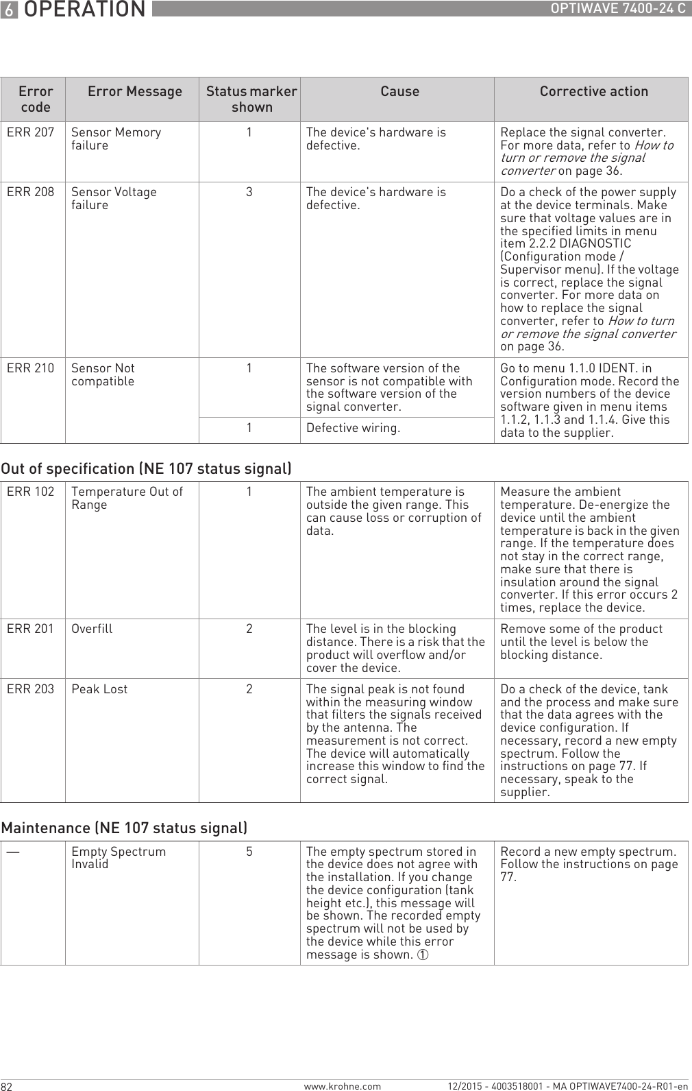
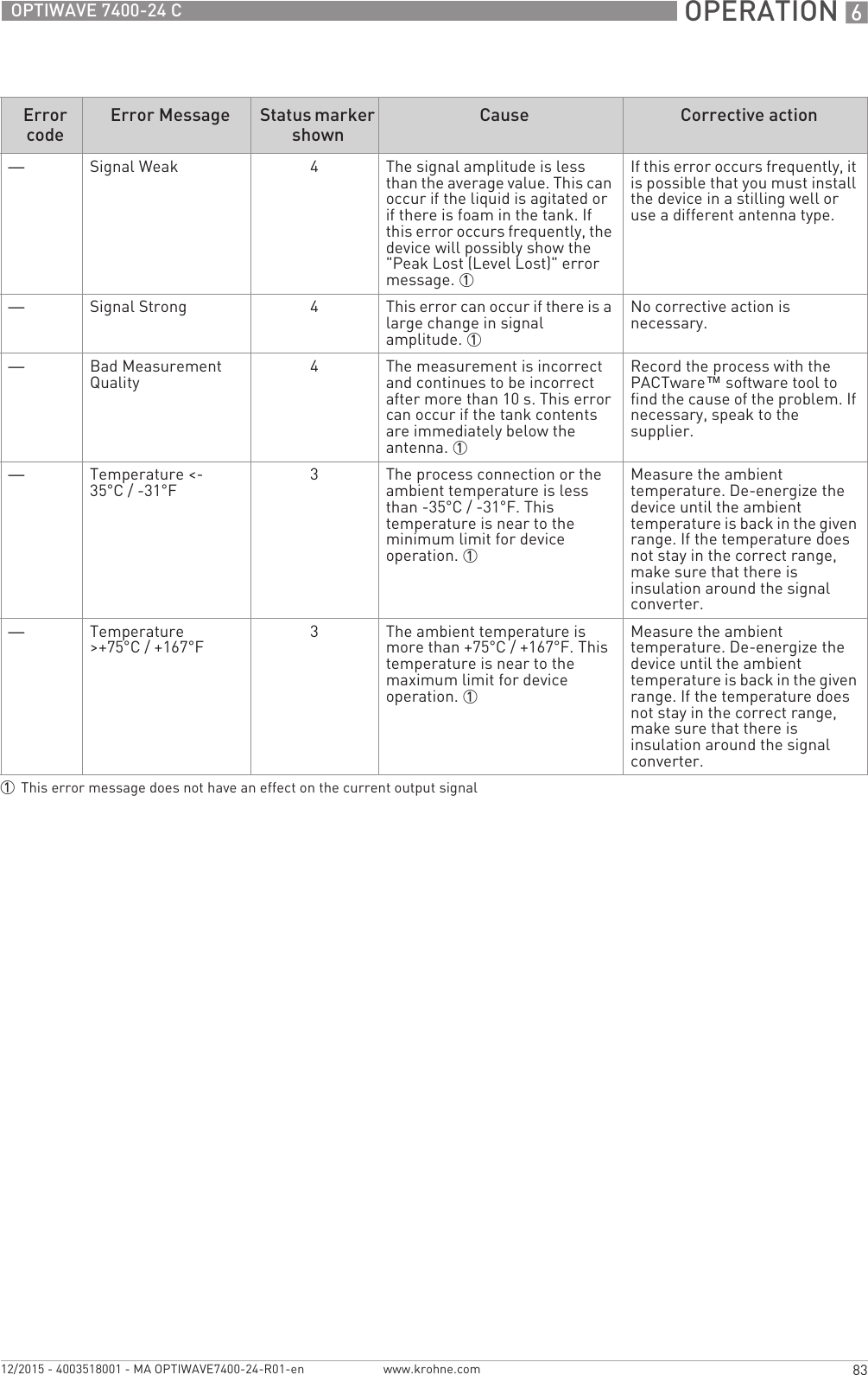
![OPERATION 679OPTIWAVE 7400-24 Cwww.krohne.com12/2015 - 4003518001 - MA OPTIWAVE7400-24-R01-en• Push [>>>>] and [] (Esc) at the same time to exit to the "save settings" window.• Select SaveSaveSaveSave and push [^^^^].iThe device will go back to operator mode.6.5 Status and error messages6.5.1 Device status (markers)If the device senses a change in device status, the display screen will show 1 or more status markers at the bottom right side of the display screen. The display screen will also show a symbol that agrees with NAMUR Recommendation NE 107 (Self-Monitoring and Diagnosis of Field Devices) and VDI/VDE 2650. This is shown at the top left side of the display screen. More data is given if you use PACTware™ software with the appropriate DTM on a PC. Error codes and data are shown on the device display screen and in the DTM.Menu item 2.2.2 DIAGNOSTIC (Configuration mode / Supervisor menu) supplies more data. This includes internal voltages, the loop current and the reset counter (watchdog timer). You can see this data on the device display screen and in the DTM.Types of error messageINFORMATION!For more data on menu items, refer to Function description on page 63 – table 2: Supervisor.Figure 6-8: Status markers1 Device status (NAMUR NE 107 symbols)2 Symbol: Failure3 Symbol: Function check4 Symbol: Out of specification5 Symbol: Maintenance6 Status marker line (marker 3 is shown)7 When the status marker is on, a number is shownNE 107 status Type of errorDescriptionFailure Error If an error message is shown in ERROR RECORD (menu item 1.3.1), the current output goes to the error signal value set in menu item RANGE I (menu item 2.4.2) after the time set in ERROR DELAY (menu item 2.4.5). For more data about menu items.Out of specification Warning If a warning message is shown, there is no effect on the current output value.Maintenance](https://usermanual.wiki/KROHNE/FMCW24G74L.Manual-English/User-Guide-2872319-Page-79.png)
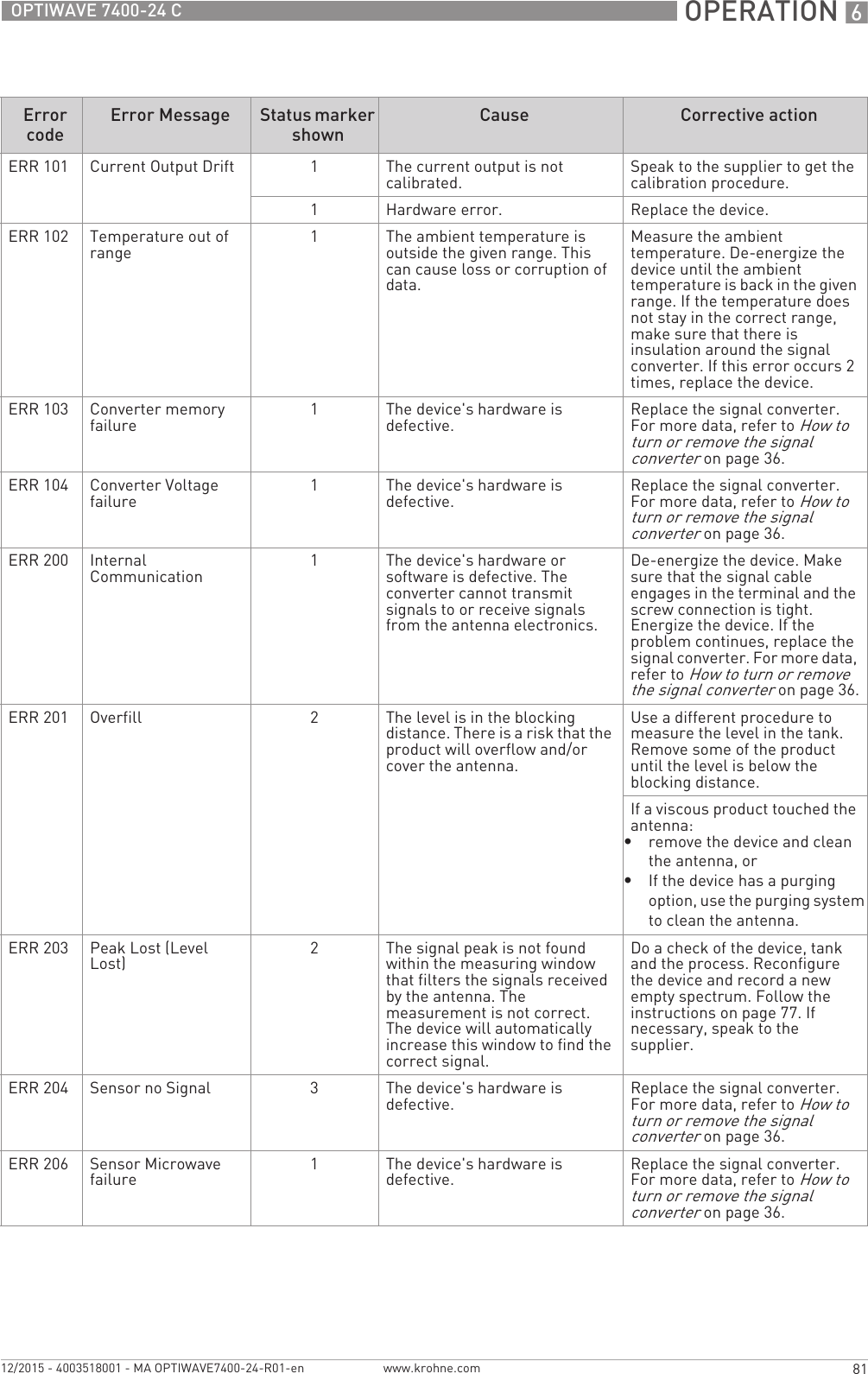
![6 OPERATION 80 OPTIWAVE 7400-24 Cwww.krohne.com 12/2015 - 4003518001 - MA OPTIWAVE7400-24-R01-enIf an "Out of specification" or a "Maintenance" status symbol is shown, refer to menu item 2.2.2 DIAGNOSTIC (Configuration mode / Supervisor menu) for more data.For data on errors, error records and error codes, refer to Error handling on page 80.6.5.2 Error handlingHow to find an error record• Push [>>>>] to enter configuration mode from normal mode.• Push [>>>>], 2 × [] and [>>>>] to go to menu item 1.3.1 ERROR RECORD.• Push 2 × [>>>>] to look at the error list. Push [] or [] for the selection of an error.iThe error record gives the number of times the error occurred and the time since the last error message.Description of errors and corrective actionsFigure 6-9: Error record data1 Error code for the error2 Number of times the error occurred3 Time since the last error record (2 days, 18 hours, 16 minutes and 43 seconds shown in this example)INFORMATION!The time since the error occurred is measured in Days (D), Hours (H), Minutes(') and Seconds ("). It only includes the time when the device is energized. The error is saved in the memory of the device when it is de-energized. The counter continues when the device is energized again.Error codeError Message Status marker shownCause Corrective actionFailure (NE 107 status signal)ERR 100 Device reset 1The device detected an internal error (watchdog timer issue). Record the data that is in menu item 2.2.2 DIAGNOSTIC (Configuration mode / Supervisor menu). Speak to the supplier.](https://usermanual.wiki/KROHNE/FMCW24G74L.Manual-English/User-Guide-2872319-Page-80.png)
![SERVICE 785OPTIWAVE 7400-24 Cwww.krohne.com12/2015 - 4003518001 - MA OPTIWAVE7400-24-R01-en7.4.2 Replacement of the OPTIWAVE 7300 signal converter with the OPTIWAVE 7400 signal converterEquipment needed:•5 mm Allen wrench (not supplied)•Slotted-tip screwdriver (not supplied)•Wrench for housing cover•Yellow / blue magnet•OPTIWAVE 7300 C radar level meter•OPTIWAVE 7400 signal converter (without process connection and antenna)•Handbooks for all devicesProcedure 1: Record the offset value (OPTIWAVE7300 radar level meter)1 Energize the device.iThe device is in operation and in normal mode.2 Push [^^^^] to go to the SERVICE menu.iThe display screen shows the text "Code 2".3 Give the password for the SERVICE menu. If you do not have the password, speak to the sup-plier.4 Push [>>>>], [] and [>>>>] to go to menu item 4.2.1 Offset. Record the offset value.5 Push 4 × [^^^^]. Push [] or [] for the selection of the save option (Store No, Store Yes or Re-turn). Set to "Store No" to cancel the changes to the device settings.6 Push [^^^^] to confirm.iThe device is in normal mode.7 De-energize the device.8 Remove the electrical cables.9 Attach the signal converter cover.INFORMATION!Complete the 5 procedures that follow in numerical sequence.To get the passwords for the OPTIWAVE 7300 and OPTIWAVE 7400 Service menus, speak to the supplier.CAUTION!Make sure that you also record device configuration data. This data includes basic configuration (tank height, blocking distance etc.), output, application, display and strapping table data. You can find this data in the Supervisor menu.INFORMATION!If you cannot start the device, record the serial number on the device nameplate and contact the supplier. The supplier will give you the offset value.](https://usermanual.wiki/KROHNE/FMCW24G74L.Manual-English/User-Guide-2872319-Page-85.png)
![7 SERVICE 86 OPTIWAVE 7400-24 Cwww.krohne.com 12/2015 - 4003518001 - MA OPTIWAVE7400-24-R01-en1 Remove the 4 socket head screws at the bottom of the signal converter with a 5 mm Allen wrench. Keep the screws for the subsequent procedure.2 Remove the signal converter from the process connection. Make sure that the gasket stays on the flange connection.1 Put the OPTIWAVE 7400 signal converter on the flange connection. Make sure that the signal converter fully engages in the mating part.2 Tighten the socket set screw at the bottom of the signal converter with a 5 mm Allen wrench.Procedure 4: How to set the correct offset value (OPTIWAVE 7400)1 Energize the device.iThe device is in operation and in normal mode. It will not measure correctly until the new correction offset value is set in menu item 3.1.4 CORR.OFFSET. 2 Push [>>>>], 2 × [] and [>>>>] to go to the SERVICE menu (3.0.0).3 Give the password for the SERVICE menu. If you do not have the password, speak to the sup-Procedure 2: How to remove the signal converter (OPTIWAVE 7300 C radar level meters)Figure 7-1: Procedure 2: How to remove the signal converter (OPTIWAVE 7300 C radar level meters)Procedure 3: How to attach the OPTIWAVE 7400 signal converterFigure 7-2: Procedure 3: How to attach the OPTIWAVE 7400 signal converter](https://usermanual.wiki/KROHNE/FMCW24G74L.Manual-English/User-Guide-2872319-Page-86.png)
![SERVICE 787OPTIWAVE 7400-24 Cwww.krohne.com12/2015 - 4003518001 - MA OPTIWAVE7400-24-R01-enplier.4 Push [>>>>] and 3 × [] to go to menu item 3.1.4 CORR.OFFSET (correction offset).5 Push [>>>>] to change the value. Enter the new correction offset value. For the applicable correc-tion offset value, refer to the table that follows.6 Push 4 × [>>>>]. Push [] or [] for the selection of the save option (STORE NO or STORE YES). Set to "STORE YES" to save and use the data.7 Push [^^^^] to confirm.iThe device is in normal mode. The device uses the new correction offset value.Procedure 5: Device configuration (OPTIWAVE 7400)1 For the Quick Setup procedure, refer to Quick Setup (Commissioning) on page 70. For more data about device configuration, refer to Operation on page 56.7.5 Spare parts availabilityThe manufacturer adheres to the basic principle that functionally adequate spare parts for each device or each important accessory part will be kept available for a period of 3 years after delivery of the last production run for the device.This regulation only applies to spare parts which are subject to wear and tear under normal operating conditions.7.6 Availability of servicesThe manufacturer offers a range of services to support the customer after expiration of the warranty. These include repair, maintenance, technical support and training.CAUTION!You recorded device configuration data of the OPTIWAVE 7300 level meter before you attached the new signal converter. Make sure that you enter this data in the supervisor menu of the OPTIWAVE 7400.INFORMATION!For more precise information, please contact your local sales office.](https://usermanual.wiki/KROHNE/FMCW24G74L.Manual-English/User-Guide-2872319-Page-87.png)
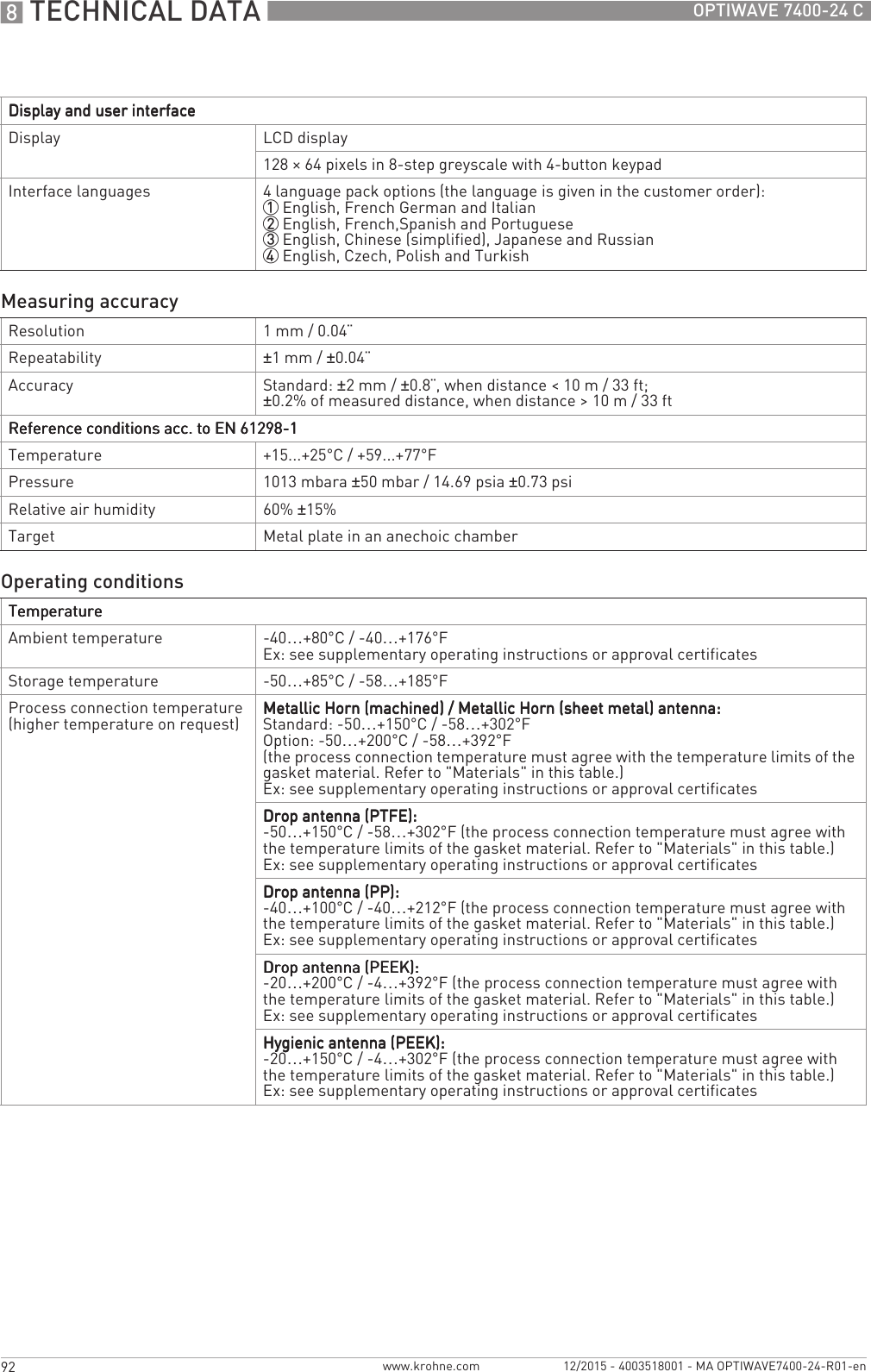
![8 TECHNICAL DATA 94 OPTIWAVE 7400-24 Cwww.krohne.com 12/2015 - 4003518001 - MA OPTIWAVE7400-24-R01-enGaskets (and o-rings for the sealed antenna extension option) Hygienic antenna:Hygienic antenna:Hygienic antenna:Hygienic antenna:BioControl®: FKM/FPM (-20…+150°C/ -4…+302°F); EPDM (-20°C…+150°C/ -4…+302°F)SMS, Tri-Clamp®, VARIVENT®, DIN 11851: without 3PTFE Drop antenna:PTFE Drop antenna:PTFE Drop antenna:PTFE Drop antenna:FKM/FPM (-40…+150°C/ -40…+302°F); Kalrez® 6375 (-20…+150°C/ -4…+302°F); EPDM (-50°C…+150°C/ -58…+302°F) 4PP Drop antenna:PP Drop antenna:PP Drop antenna:PP Drop antenna:FKM/FPM (-40…+100°C/ -40…+212°F); Kalrez® 6375 (-20…+100°C/ -4…+212°F); EPDM (-40°C…+100°C/ -40…+212°F) 4PEEK Drop antenna:PEEK Drop antenna:PEEK Drop antenna:PEEK Drop antenna:FKM/FPM (-40…+200°C/ -40…+392°F); Kalrez® 6375 (-20…+200°C/ -4…+392°F); EPDM (-40°C…+150°C/ -40…+203°F) 4Metallic Horn antenna:Metallic Horn antenna:Metallic Horn antenna:Metallic Horn antenna:FKM/FPM (-40…+200°C/ -40…+390°F); Kalrez® 6375 (-20…+200°C/ -4…+390°F); EPDM (-50°C…+150°C/ -58…+300°F)Feedthrough Standard: PEI (-50...+200°C / -58...+392°F – max. range. The feedthrough temperature limits must agree with the temperature limits of the gasket material and antenna type. If the distance piece option is not attached, the maximum temperature is 150°C/ 300°F.)Option: Metaglas® (-30...+200°C / -22...+392°F – max. range. The feedthrough temperature limits must agree with the temperature limits of the gasket material and antenna type. If the distance piece option is not attached, the maximum temperature is 150°C/ 300°F.)Cable gland Standard: noneOptions: Plastic (Non-Ex: black, Ex i-approved: blue); nickel-plated brass; stainless steelWeather protection (Option) Stainless steel (1.4404 / 316L)Process connectionsThread G1½ (ISO 228); 1½NPT (ASME B1.20.1)Flange versionFlange versionFlange versionFlange versionEN 1092-1 DN40…200 in PN16 or PN40 (Type B1), DN40…150 in PN63 or PN100 (Type B1); others on requestOptional flange facing: Types C, D, E and FASME B16.5 1½¨…8¨ in 150 lb RF, 1½¨...6¨ in 300 lb RF, 1½¨...4¨ in 600 lb or 900 lb RF; 1½¨...2¨ in 1500 lb RJ; others on requestOptional flange facing: RJ (Ring Joint)JIS B2220 40…100A in 10K; others on requestHygienic BioControl® DN50; Tri-Clamp® 2¨; DIN 11851 DN50; SMS 51; VARIVENT® DN50; others on requestOther Others on requestElectrical connectionsPower supply Terminals output Terminals output Terminals output Terminals output – Non-Ex / Ex i: Non-Ex / Ex i: Non-Ex / Ex i: Non-Ex / Ex i:14…30 VDC; min./max. value for an output of 22 mA at the terminalsTerminals output Terminals output Terminals output Terminals output – Ex d: Ex d: Ex d: Ex d:20…36 VDC; min./max. value for an output of 22 mA at the terminalsMaximum current 22 mACurrent output load Non-Ex / Ex i:Non-Ex / Ex i:Non-Ex / Ex i:Non-Ex / Ex i: RL [Ω] ≤ ((Uext -12 V)/22 mA). For more data, refer to Minimum power supply voltage on page 99.Ex d:Ex d:Ex d:Ex d: RL [Ω] ≤ ((Uext -16 V)/22 mA). For more data, refer to Minimum power supply voltage on page 99.Cable entry Standard: M20×1.5; Option: ½NPT](https://usermanual.wiki/KROHNE/FMCW24G74L.Manual-English/User-Guide-2872319-Page-94.png)
![8 TECHNICAL DATA 96 OPTIWAVE 7400-24 Cwww.krohne.com 12/2015 - 4003518001 - MA OPTIWAVE7400-24-R01-enExplosion protectionExplosion protectionExplosion protectionExplosion protectionATEX (Ex ia or Ex d)DEKRA xxATEXxxxx X(pending)Compact versionCompact versionCompact versionCompact versionII 1/2 G, 2 G Ex ia IIC T6...T2 Ga/Gb or Ex ia IIC T6...T2 Gb;II 1/2 D, 2 D Ex ia IIIC T90°C Da/Db or Ex ia IIIC T90°C Db IP6X;II 1/2 G, 2 G Ex d ia IIC T6...T2 Ga/Gb or Ex d ia IIC T6...T2 Gb;II 1/2 D, 2 D Ex ia tb IIIC T90°C Da/Db or Ex ia tb IIIC T90°C Db IP6XRemote version, transmitterRemote version, transmitterRemote version, transmitterRemote version, transmitterII 2 G Ex ia [ia Ga] IIC T6...T4 Gb;II 2 D Ex ia [ia Da] IIIC T90°C Db;II 2 G Ex d ia [ia Ga] IIC T6...T4 Gb;II 2 D Ex ia tb [ia Da] IIIC T90°C DbRemote version, sensorRemote version, sensorRemote version, sensorRemote version, sensorII 1/2 G Ex ia IIC T6...T2 Ga/GbII 1/2 D Ex ia IIIC T90°C Da/DbII 1/2 G Ex ia IIC T6...T2 GbII 1/2 D Ex ia IIIC T90°C DbATEX (Ex ic)DEKRA xxATEXxxxx X(pending)Compact versionCompact versionCompact versionCompact versionII 3 G Ex ic IIC T6...T2 Gc;II 3 D Ex ic IIIC T90°C DcRemote version, transmitterRemote version, transmitterRemote version, transmitterRemote version, transmitterII 3 G Ex ic [ic] IIC T6...T4 Gc;II 3 D Ex ic [ic] IIIC T90°C DcRemote version, sensorRemote version, sensorRemote version, sensorRemote version, sensorII 3 G Ex ic IIC T6...T2 Gc;II 3 D Ex ic IIIC T90°C DcIECExIECEx DEK xx.xxxx X(pending)Compact versionCompact versionCompact versionCompact versionEx ia IIC T6…T2 Ga/Gb or Ex ia IIC T6…T2 Gb or Ex ic IIC T6…T2 Gc;Ex ia IIIC T90°C Da/Db or Ex ia IIIC T90°C Db or Ex ic IIIC T90°C Dc;Ex d ia IIC T6...T2 or Ex d ia IIIC T6...T2 Gb;Ex ia tb IIIC T90°C Da/Db or Ex ia tb IIIC T90°C DbRemote version, transmitterRemote version, transmitterRemote version, transmitterRemote version, transmitterEx ia [ia Ga] IIC T6…T4 Gb or Ex ic IIC T6…T4 Gc;Ex ia [ia Da] IIIC T90°C Db or Ex ic [ic] IIIC T90°C Dc;Ex d ia [ia Ga] IIC T6...T4 Gb;Ex ia tb [ia Da] IIIC T90°C DbRemote version, sensorRemote version, sensorRemote version, sensorRemote version, sensorEx ia IIC T6…T2 Ga/Gb or Ex ia IIC T6…T2 Gb or Ex ic IIC T6…T2 Gc;Ex ia IIIC T90°C Da/Db or Ex ia IIIC T90°C Db or Ex ic IIIC T90°C Dc](https://usermanual.wiki/KROHNE/FMCW24G74L.Manual-English/User-Guide-2872319-Page-96.png)
![TECHNICAL DATA 897OPTIWAVE 7400-24 Cwww.krohne.com12/2015 - 4003518001 - MA OPTIWAVE7400-24-R01-encFMus - Dual Seal-approved(pending) NEC 500 (Division ratings)NEC 500 (Division ratings)NEC 500 (Division ratings)NEC 500 (Division ratings)XP-AIS / Cl. I / Div. 1 / Gr. ABCD / T6-T1;DIP / Cl. II, III / Div. 1 / Gr. EFG / T6-T1;IS / Cl. I, II, III / Div. 1 / Gr. ABCDEFG / T6-T1;NI / Cl. I / Div. 2 / Gr. ABCD / T6-T1NEC 505 (Zone ratings)NEC 505 (Zone ratings)NEC 505 (Zone ratings)NEC 505 (Zone ratings)Cl. I / Zone 0 / AEx d [ia] / IIC / T6-T1;Cl. I / Zone 0 / AEx ia / IIC / T6-T1;Cl. I / Zone 2 / AEx nA / IIC / T6-T1;Zone 20 / AEx ia / IIIC / T90°CZone 20 / AEx tb [ia] / IIIC / T90°CHazardous (Classified) Locations, indoor/outdoor Type 4X and 6P, IP66, Dual SealCEC Section 18 (Zone ratings)CEC Section 18 (Zone ratings)CEC Section 18 (Zone ratings)CEC Section 18 (Zone ratings)Cl. I, Zone 0, Ex d [ia], IIC, T6-T1;Cl. I, Zone 0, Ex ia, IIC, T6-T1;Cl. I, Zone 2, Ex nA, IIC, T6-T1CEC Section 18 and Annex J (Division ratings)CEC Section 18 and Annex J (Division ratings)CEC Section 18 and Annex J (Division ratings)CEC Section 18 and Annex J (Division ratings)XP-AIS / Cl. I / Div. 1 / Gr. BCD / T6-T1DIP / Cl. II, III / Div. 1 / Gr. EFG / T6-T1IS/ Cl.I/ Div.1/ Gr.BCD/ T6-T1NI / Cl. I / Div. 2 / Gr. ABCD / T6-T1NEPSIGYJxxxxxx/xx(pending)Ex ia IIC T2~T6 Gb or Ex ia IIC T2~T6 Ga/Gb DIP A20/A21 TA T90°C IP6XEx d ia IIC T2~T6 Gb or Ex d ia IIC T2~T6 Ga/Gb DIP A20/A21 TA T90°C IP6XDNV / INMETRODNV 14.00xx X(pending)Ex ia IIC T6…T3 Ga; Ex ia IIIC T70°C...T95°C Da IP6X;Ex d [ia Ga] IIC T6...T3 Ga/Gb; Ex tb [ia Da] IIIC T70°C...T95°C Db IP6XOther standards and approvalsOther standards and approvalsOther standards and approvalsOther standards and approvalsSIL- only for 4...20 mA HART output Compact version and 4...20 mA HART output only: SIL 2 for high/low demand mode operationEMC Electromagnetic Compatibility DirectiveSIL 2-approved devicesRadio approvals R & TTER & TTER & TTER & TTERadio Equipment and Telecommunications Terminal Equipment DirectiveFCC RulesFCC RulesFCC RulesFCC RulesPart 15Industry CanadaIndustry CanadaIndustry CanadaIndustry CanadaRSS-211LVD Agrees with the safety part of the Low-Voltage DirectiveNAMUR NAMUR NE 21 Electromagnetic Compatibility (EMC) of Industrial Process and Laboratory Control EquipmentNAMUR NE 43 Standardization of the Signal Level for the Failure Information of Digital TransmittersNAMUR NE 53 Software and Hardware of Field Devices and Signal Processing Devices with Digital ElectronicsNAMUR NE 107 Self-Monitoring and Diagnosis of Field Devices](https://usermanual.wiki/KROHNE/FMCW24G74L.Manual-English/User-Guide-2872319-Page-97.png)
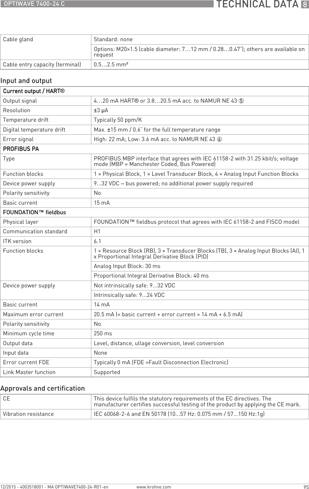
![TECHNICAL DATA 899OPTIWAVE 7400-24 Cwww.krohne.com12/2015 - 4003518001 - MA OPTIWAVE7400-24-R01-en8.3 Minimum power supply voltageUse these graphs to find the minimum power supply voltage for a given current output load.Non-Ex and Hazardous Location approved (Ex i / IS) devicesFigure 8-2: Minimum power supply voltage for an output of 22 mA at the terminal (Non-Ex and Hazardous Location approval (Ex i / IS))X: Power supply U [VDC]Y: Current output load RL [Ω]Hazardous Location (Ex d / XP/NI) approved devicesFigure 8-3: Minimum power supply voltage for an output of 22 mA at the terminal (Hazardous Location approval (Ex d / XP/NI))X: Power supply U [VDC]Y: Current output load RL [Ω]](https://usermanual.wiki/KROHNE/FMCW24G74L.Manual-English/User-Guide-2872319-Page-99.png)
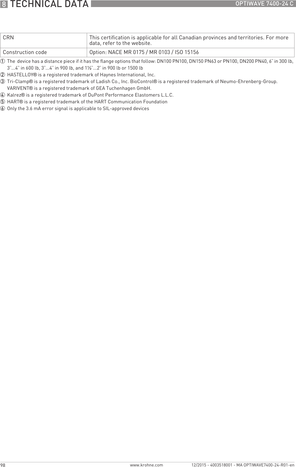
![8 TECHNICAL DATA 100 OPTIWAVE 7400-24 Cwww.krohne.com 12/2015 - 4003518001 - MA OPTIWAVE7400-24-R01-en8.4 Antenna selectionThe graphs below show which antenna to select for the application based on:•D, the measuring range,•εr, is the dielectric constant of the product being measuredFigure 8-4: Selection of antenna for liquid applications (graph of distance in m against εr)Figure 8-5: Selection of antenna for liquid applications (graph of distance in ft against εr)1 Distance, D [m]2 Distance, D [ft]3 Dielectric constant (εr) range for storage/still well applications4 Dielectric constant (εr) range for process/agitator applications5 DN80, DN100, DN150 or DN200 Horn antenna with a still well, or DN150 or DN200 Horn antenna without a still well6 DN80, DN100, DN150 or DN200 Horn antenna with or without a still well, or DN80 or DN150 Drop antenna without a still well7 DN40, DN50, DN80, DN100, DN150 or DN200 Horn antenna with or without a still well, DN80 or DN150 Drop antenna without a still well or Hygienic antenna](https://usermanual.wiki/KROHNE/FMCW24G74L.Manual-English/User-Guide-2872319-Page-100.png)
![TECHNICAL DATA 8103OPTIWAVE 7400-24 Cwww.krohne.com12/2015 - 4003518001 - MA OPTIWAVE7400-24-R01-en8.6 Dimensions and weightsDimensions and weights in mm and kgDimensions and weights in inches and lbDN40/1.5¨ Metallic Horn (machined) antenna versionsFigure 8-8: DN40 or 1.5¨ horn antenna versions1 DN40/1.5¨ horn antenna with G 1½ or 1½NPT thread connection2 DN40/1.5¨ horn antenna with flange connectionINFORMATION!•Cable glands are delivered on demand with non-Ex, Ex i- and Ex d-approved devices.•The diameter of the outer sheath of the cable must be 7…12 mm or 0.28…0.47¨.•Cable glands for cFMus-approved devices must be supplied by the customer.•A weather protection cover is available as an accessory with all devices.Dimensions [mm] Weights [kg]a b c d e f h ØiThread connection??? 1 ??? ??? ??? ??? 32 126 2 39 ???Flange connection??? 1 ??? ??? ??? 3 ??? 3 45 3 96 2 39 ??...??1If fitted with standard cable glands2Additional antenna extensions of Ø39 × length 105 mm are available3With ¼NPTF purge connection option: add 17 mm to this dimension. With distance piece option: add 71 mm to this dimension.Dimensions [inches] Weights [lb]a b c d e f h ØiThread connection??? 1 ??? ??? ??? ??? 1.3 4.9 2 1.5 ???Flange connection??? 1 ??? ??? ??? 3 ??? 3 1.8 3 3.8 2 1.5 ??...??1If fitted with standard cable glands2Additional antenna extensions of Ø1.5 × length 4.1¨ are available3With ¼NPTF purge connection option: add 0.7¨ to this dimension. With distance piece option: add 2.8¨ to this dimension.](https://usermanual.wiki/KROHNE/FMCW24G74L.Manual-English/User-Guide-2872319-Page-103.png)
![TECHNICAL DATA 8105OPTIWAVE 7400-24 Cwww.krohne.com12/2015 - 4003518001 - MA OPTIWAVE7400-24-R01-enDimensions and weights in mm and kgDimensions and weights in inches and lbDimensions [mm] Weight [kg]a b c d e f h ØiThread connection??? 1 ??? ??? ??? ??? 32 136 2 43 ???Flange connection??? 1 ??? ??? ??? 3 ??? 3 45 3 107 2 43 ??...??1If fitted with standard cable glands2Additional antenna extensions of Ø39 × length 105 mm are available3With ¼NPTF purge connection option: add 17 mm to this dimension. With distance piece option: add 71 mm to this dimension.Dimensions [inches] Weights [lb]a b c d e f h ØiThread connection??? 1 ??? ??? ??? ??? 1.3 5.3 2 1.7 ???Flange connection??? 1 ??? ??? ??? 3 ??? 3 1.8 3 4.2 2 1.7 ??...??1If fitted with standard cable glands2Additional antenna extensions of Ø1.5 × length 4.1¨ are available3With ¼NPTF purge connection option: add 0.7¨ to this dimension. With distance piece option: add 2.8¨ to this dimension.](https://usermanual.wiki/KROHNE/FMCW24G74L.Manual-English/User-Guide-2872319-Page-105.png)
![TECHNICAL DATA 8107OPTIWAVE 7400-24 Cwww.krohne.com12/2015 - 4003518001 - MA OPTIWAVE7400-24-R01-enDimensions and weights in mm and kgDimensions and weights in inches and lbDimensions [mm] Weights [kg]a b c d e f h ØiThread connectionDN65/2.5¨??? 1 ??? ??? ??? ??? ??? ??? 2 ??DN80/3¨??? 1 ??? ??? ??? ??? 33 249 2 75 ??DN100/4¨??? 1 ??? ??? ??? ??? 33 318 2 95 ??DN150/6¨??? 1 ??? ??? ??? ??? 33 486 2 144 ??DN200/8¨??? 1 ??? ??? ??? ??? 33 644 2 190 ??Flange connectionDN65/2.5¨??? 1 ??? ??? ??? 3 ??? 3 45 3 ??? 2 ?? ??DN80/3¨??? 1 ??? 201 ??? 3 ??? 3 45 3 221 2 75 ??DN100/4¨??? 1 ??? 201 ??? 3 ??? 3 45 3 290 2 95 ??DN150/6¨??? 1 ??? 201 ??? 3 ??? 3 45 3 458 2 144 ??DN200/8¨??? 1 ??? ??? ??? 3 ??? 3 45 3 616 2 190 ??1If fitted with standard cable glands2Additional antenna extensions of Ø39 × length 105 mm are available3With ¼NPTF purge connection option: add 17 mm to this dimension. With distance piece option: add 71 mm to this dimension.Dimensions [inches] Weights [lb]a b c d e f h ØiThread connectionDN65/2.5¨??? 1 ??? ??? ??? ??? ??? ??? 2 ??? ???DN80/3¨??? 1 ??? ??? ??? ??? 1.3 9.8 2 3.0 ???DN100/4¨??? 1 ??? ??? ??? ??? 1.3 12.5 2 3.7 ???DN150/6¨??? 1 ??? ??? ??? ??? 1.3 19.1 2 5.7 ???DN200/8¨??? 1 ??? ??? ??? ??? 1.3 25.4 2 7.5 ???Flange connectionDN65/2.5¨??? 1 ??? ??? ??? 3 ??? 3 1.8 3 ??? 2 ??? ???DN80/3¨??? 1 ??? ??? ??? 3 ??? 3 1.8 3 8.7 2 3.0 ???DN100/4¨??? 1 ??? ??? ??? 3 ??? 3 1.8 3 11.4 2 3.7 ???DN150/6¨??? 1 ??? ??? ??? 3 ??? 3 1.8 3 18.0 2 5.7 ???DN200/8¨??? 1 ??? ??? ??? 3 ??? 3 1.8 3 24.3 2 7.5 ???1If fitted with standard cable glands2Additional antenna extensions of Ø1.5 × length 4.1¨ are available3With ¼NPTF purge connection option: add 0.7¨ to this dimension. With distance piece option: add 2.8¨ to this dimension.](https://usermanual.wiki/KROHNE/FMCW24G74L.Manual-English/User-Guide-2872319-Page-107.png)
![TECHNICAL DATA 8109OPTIWAVE 7400-24 Cwww.krohne.com12/2015 - 4003518001 - MA OPTIWAVE7400-24-R01-enDimensions and weights in mm and kgDimensions and weights in inches and lbDimensions [mm] Weights [kg]a b c d e f h Øi jThread connection ???1??? ??? ??? ??? 33 165274 –??…??Flange connection ???1??? ??? ??? ??? 45 137274 –??…??Flange connection with flange plate protection option???1??? ??? ??? ??? 45 137 74 39 ??…??1If fitted with standard cable glands2Additional antenna extensions of Ø39 × length 105 mm are available. Do not attach more than 5 antenna extensions.Dimensions [inches] Weights [lb]a b c d e f h Øi jThread connection ???1??? ??? ??? ??? 1.3 6.5 2 2.9 –??…??Flange connection ???1??? ??? ??? ??? 1.8 5.4 2 2.9 –??…??Flange connection with flange plate protection option???1??? ??? ??? ??? 1.8 5.4 2.9 1.5 ??…??1If fitted with standard cable glands2Additional antenna extensions of Ø1.5 × length 4.1¨ available. Do not attach more than 5 antenna extensions.](https://usermanual.wiki/KROHNE/FMCW24G74L.Manual-English/User-Guide-2872319-Page-109.png)
![TECHNICAL DATA 8111OPTIWAVE 7400-24 Cwww.krohne.com12/2015 - 4003518001 - MA OPTIWAVE7400-24-R01-enDimensions and weights in mm and kgDimensions and weights in inches and lbDimensions [mm] Weights [kg]a b c d e f h Øi j kThread connection ?? 1 ?? ?? ?? ?? 33 2422144 – – ??Flange connection ?? 1 ?? ?? ?? ?? 45 2142144 – – ??…??Flange connection with flange plate protection option?? 1 ?? ?? ?? ?? 45 214 144 39 – –1If fitted with standard cable glands2Additional antenna extensions of Ø39 × length 105 mm are available. Do not attach more than 5 antenna extensions.Dimensions [inches] Weights [lb]a b c d e f h Øi j kThread connection ?? 1 ?? ?? ?? ?? 1.3 9.525.7 – – ??Flange connection ?? 1 ?? ?? ?? ?? 1.8 8.425.7 – – ??…??Flange connection with flange plate protection option?? 1 ?? ?? ?? ?? 1.8 8.4 5.7 1.5 – –1If fitted with standard cable glands2Additional antenna extensions of Ø1.5 × length 4.1¨ are available. Do not attach more than 5 antenna extensions.](https://usermanual.wiki/KROHNE/FMCW24G74L.Manual-English/User-Guide-2872319-Page-111.png)
![8 TECHNICAL DATA 112 OPTIWAVE 7400-24 Cwww.krohne.com 12/2015 - 4003518001 - MA OPTIWAVE7400-24-R01-enDimensions and weights in mm and kgDimensions and weights in inches and lbDimensions [mm] Weights [kg]a b d hDIN 11851 connection ??? 1 ??? ??? 8???Tri-Clamp® connection ??? 1 ??? ??? 8???Neumo BioControl® connection ??? 1 ??? ??? 25 ???SMS connection ??? 1 ??? ??? 8???VARIVENT® connection ??? 1 ??? ??? 25 ???1If fitted with standard cable glandsDimensions [inches] Weights [lb]a b d hDIN 11851 connection ??? 1 ??? 1 ??? 1 0.3 ??? 1Tri-Clamp® connection ??? 1 ??? 1 ??? 1 0.3 ??? 1Neumo BioControl® connection ??? 1 ??? 1 ??? 1 1.0 ??? 1SMS connection ??? 1 ??? 1 ??? 1 0.3 ??? 1VARIVENT® connection ??? 1 ??? 1 ??? 1 1.0 ??? 11If fitted with standard cable glands](https://usermanual.wiki/KROHNE/FMCW24G74L.Manual-English/User-Guide-2872319-Page-112.png)
![TECHNICAL DATA 8113OPTIWAVE 7400-24 Cwww.krohne.com12/2015 - 4003518001 - MA OPTIWAVE7400-24-R01-enType of housing WeightsAluminium housing Stainless steel housing[kg] [lb] [kg] [lb]Compact ?? ?? ?? ??Remote converter 1 ?? ?? ?? ??Antenna housing 2 ?? ?? ?? ??1The remote version of the device has a "remote converter" and a "probe housing". For more data, refer to "Housing dimensions" at the start of this section.2The remote version of the device has a "remote converter" and a "antenna housing". For more data, refer to "Housing dimensions" at the start of this section.Type of housing WeightsAluminium housing Stainless steel housing[kg] [lb] [kg] [lb]Compact ?? ?? ?? ??](https://usermanual.wiki/KROHNE/FMCW24G74L.Manual-English/User-Guide-2872319-Page-113.png)
![8 TECHNICAL DATA 114 OPTIWAVE 7400-24 Cwww.krohne.com 12/2015 - 4003518001 - MA OPTIWAVE7400-24-R01-enAntenna option weightsAntenna options Min./Max. weights[kg] [lb]Standard options, without converterStandard options, without converterStandard options, without converterStandard options, without converterDN40 / 1.5¨ Metallic Horn antenna with flange connection, standard length ??...?? ??...??DN50 / 2¨ Metallic Horn antenna with flange connection, standard length ??...?? ??...??DN65 / 2.5¨ Metallic Horn antenna with flange connection, standard length ??...?? ??...??DN100 / 4¨ Metallic Horn antenna with flange connection, standard length 5.6...37.1 12.3...81.8DN100 / 4¨ Metallic Horn antenna with flange connection, standard length 9.1...37.2 20.1...82DN150 / 6¨ Metallic Horn antenna with flange connection, standard length 13.6...37.5 30...82.7DN200 / 8¨ Metallic Horn antenna with flange connection, standard length 14.0..37.8 30.9...83.3DN80 Drop antenna with thread connection, standard length ??...?? ??...??DN150 Drop antenna with thread connection, standard length ??...?? ??...??Antenna extension optionsAntenna extension optionsAntenna extension optionsAntenna extension optionsStraight extension, length 105 mm 1 +?? +??Straight extension, length 210 mm 1 +?? +??Straight extension, length 315 mm 1 +?? +??Straight extension, length 420 mm 1 +?? +??Straight extension, length 525 mm 1 +?? +??Straight extension, length 630 mm 2 +?? +??Straight extension, length 735 mm 2 +?? +??Straight extension, length 840 mm 2 +?? +??Straight extension, length 945 mm 2 +?? +??Straight extension, length 1050 mm 2 +?? +??"L" (right-angle) extension 2 +?? +??Other optionsOther optionsOther optionsOther optionsHT extension 3 +?? +??Flange plate option +?? +??1This option is for Metallic Horn and Drop antenna options2This option is for Metallic Horn antenna options3This component is only for the Metallic Horn and Wave Guide antennas. It is attached between the signal converter and the flange if the process connection temperature is +150...+250°C / +302...+482°F.Antenna options Min./Max. weights[kg] [lb]Standard options, without converterStandard options, without converterStandard options, without converterStandard options, without converterDN50 / 2¨ Hygienic antenna with clamp connection ??...?? ??...??DN50 / 2¨ Hygienic antenna with thread connection ??...?? ??...??](https://usermanual.wiki/KROHNE/FMCW24G74L.Manual-English/User-Guide-2872319-Page-114.png)
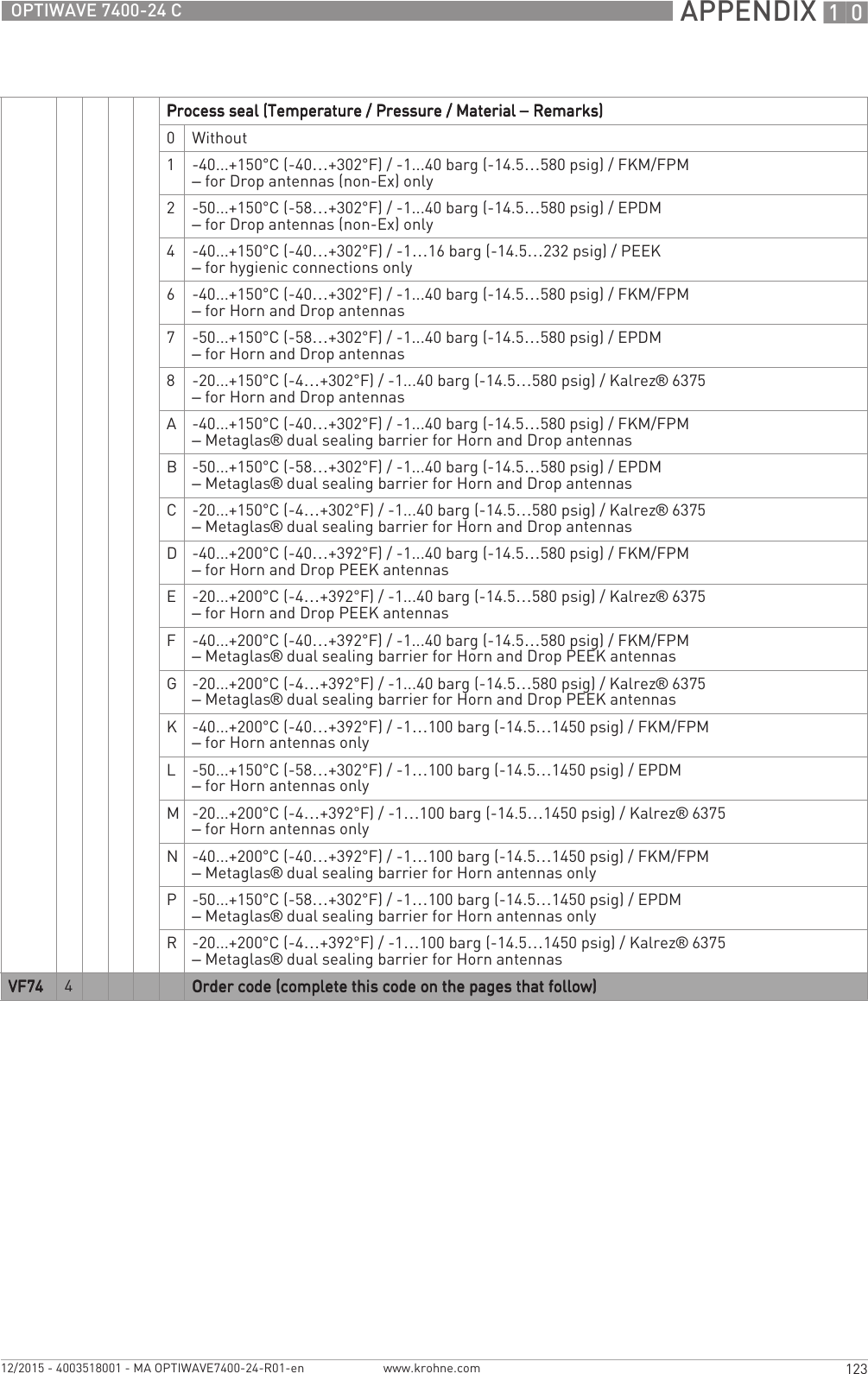
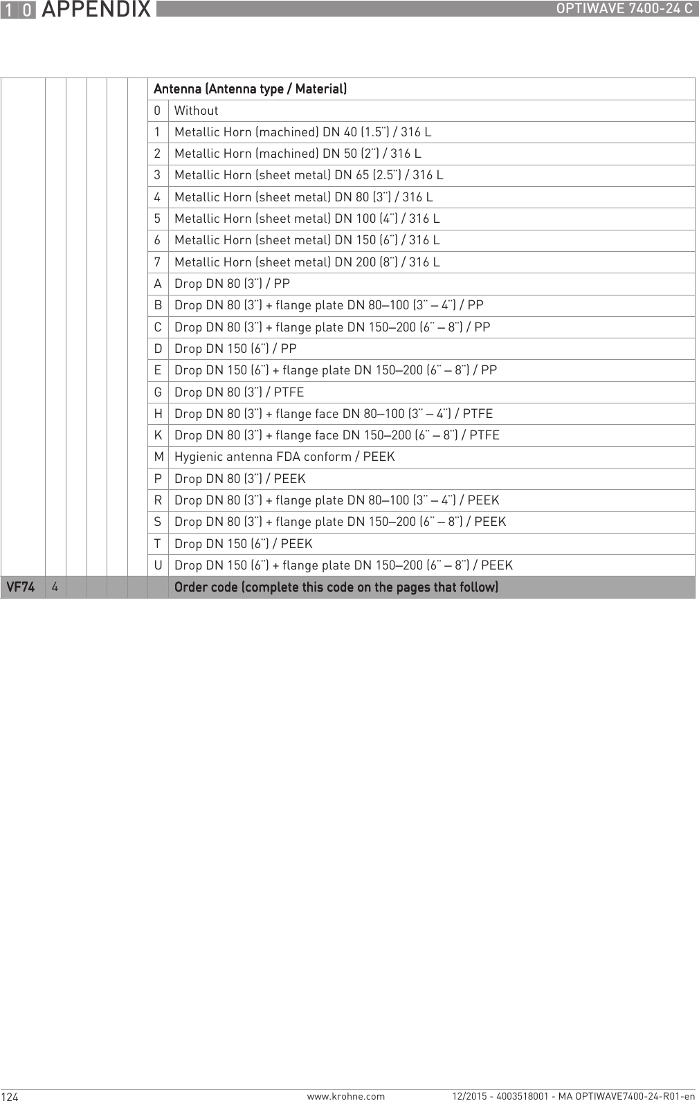
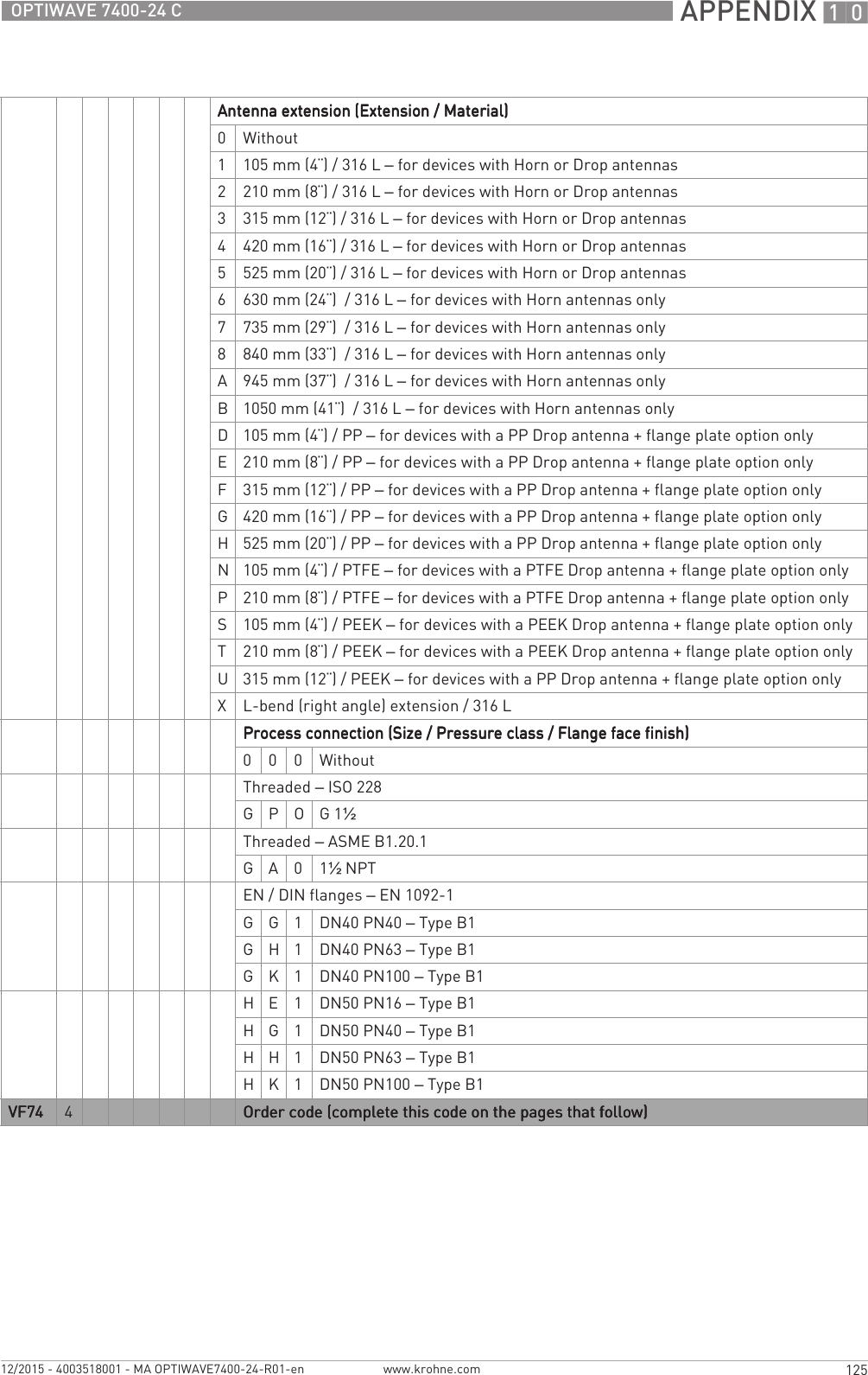
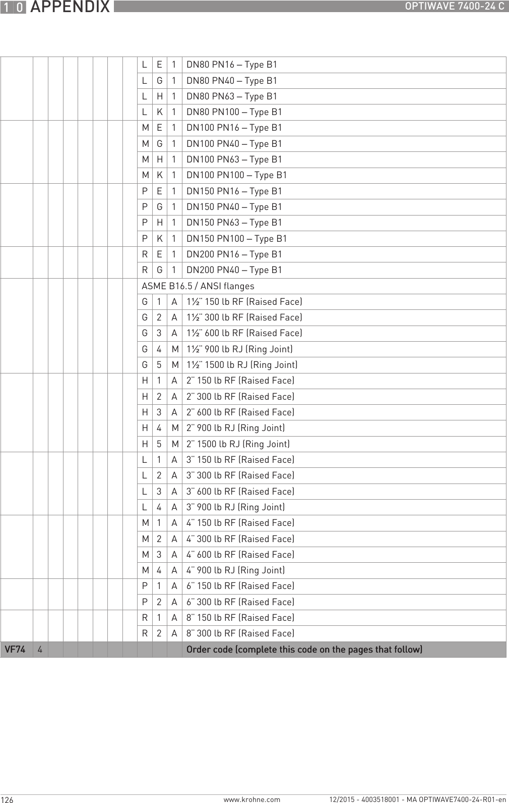
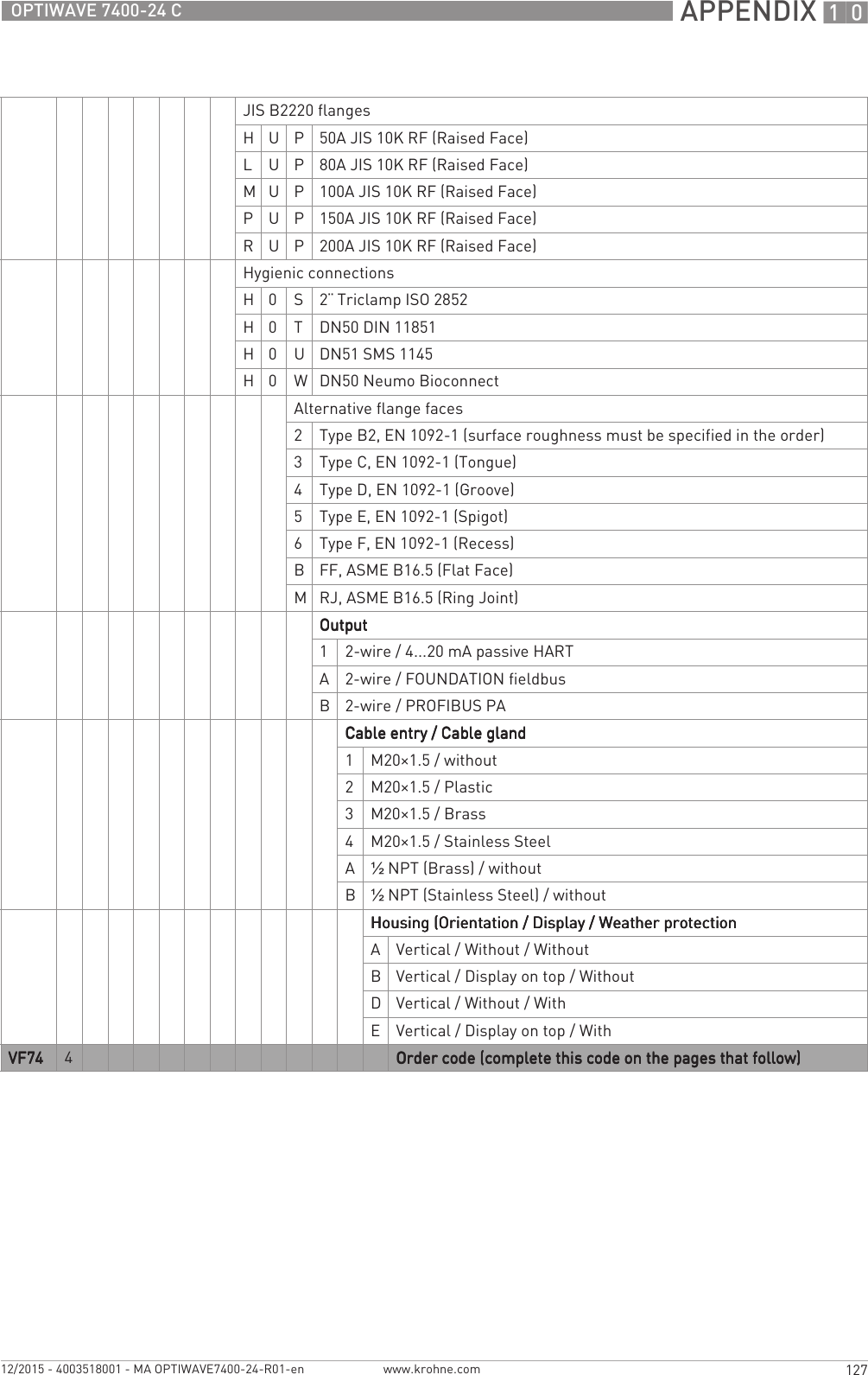
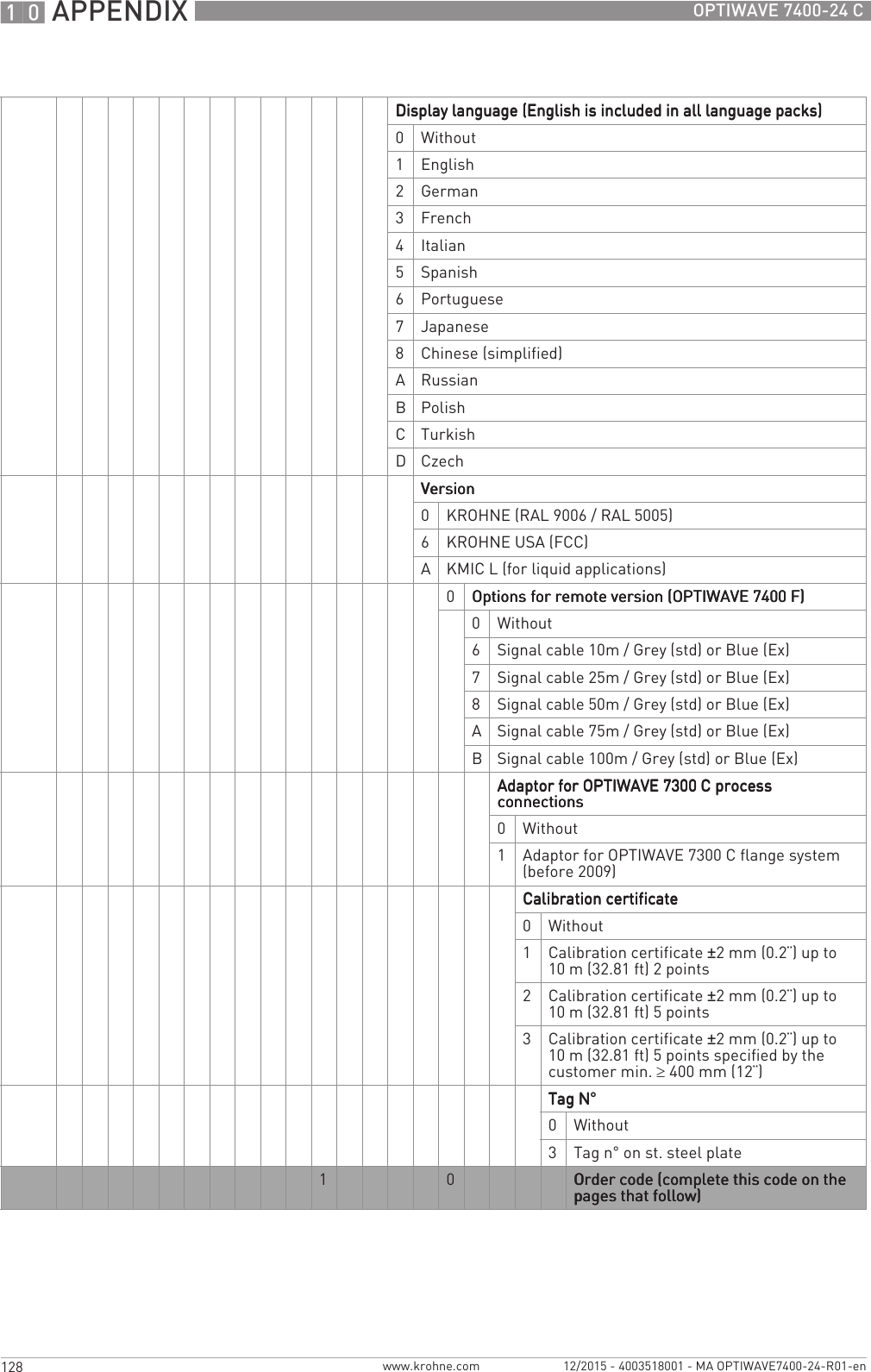
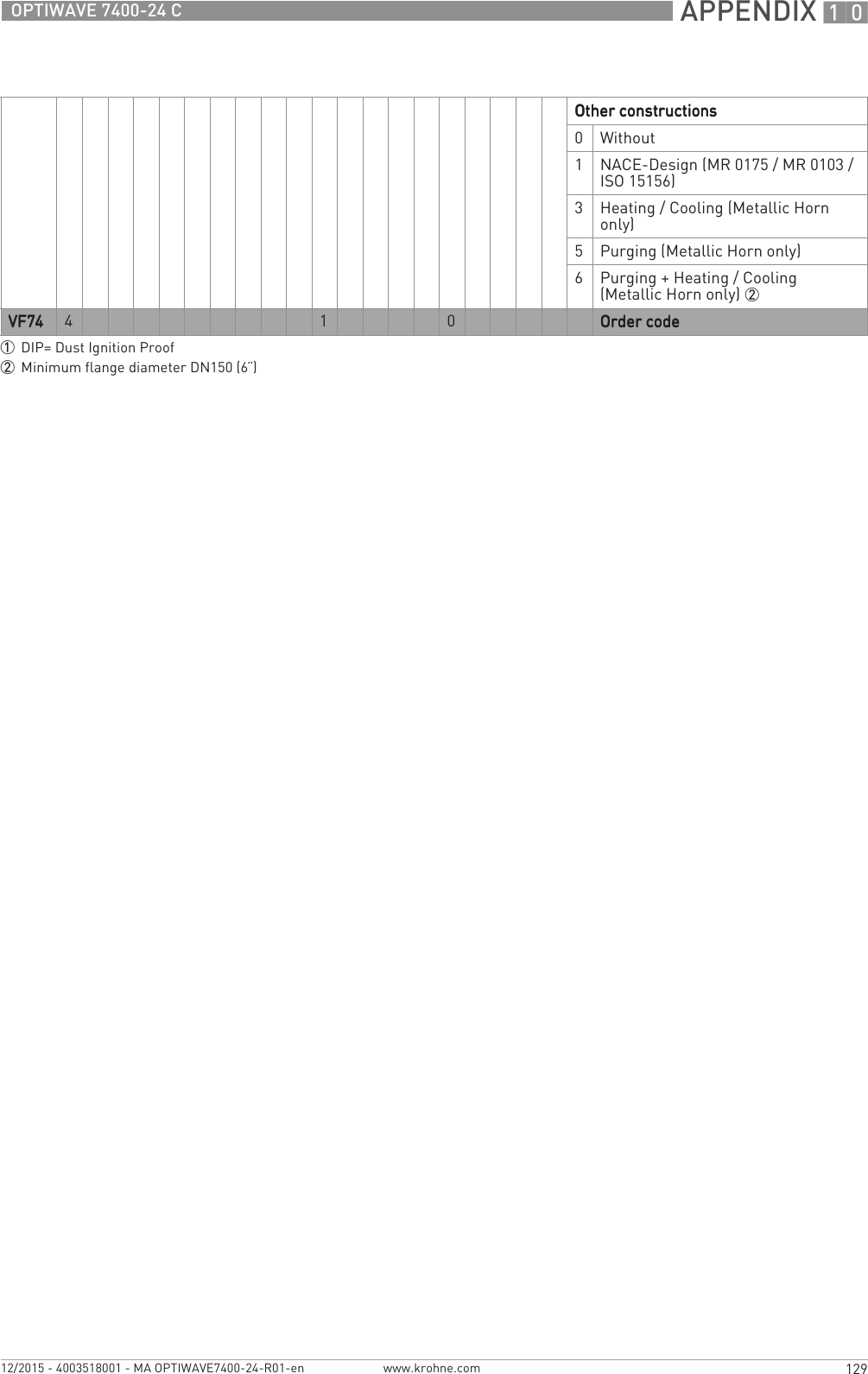
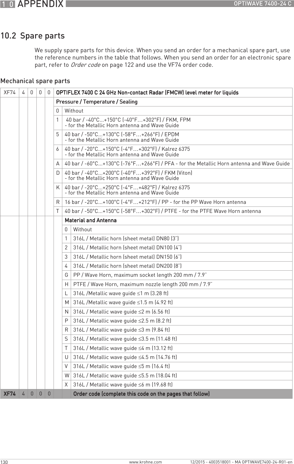
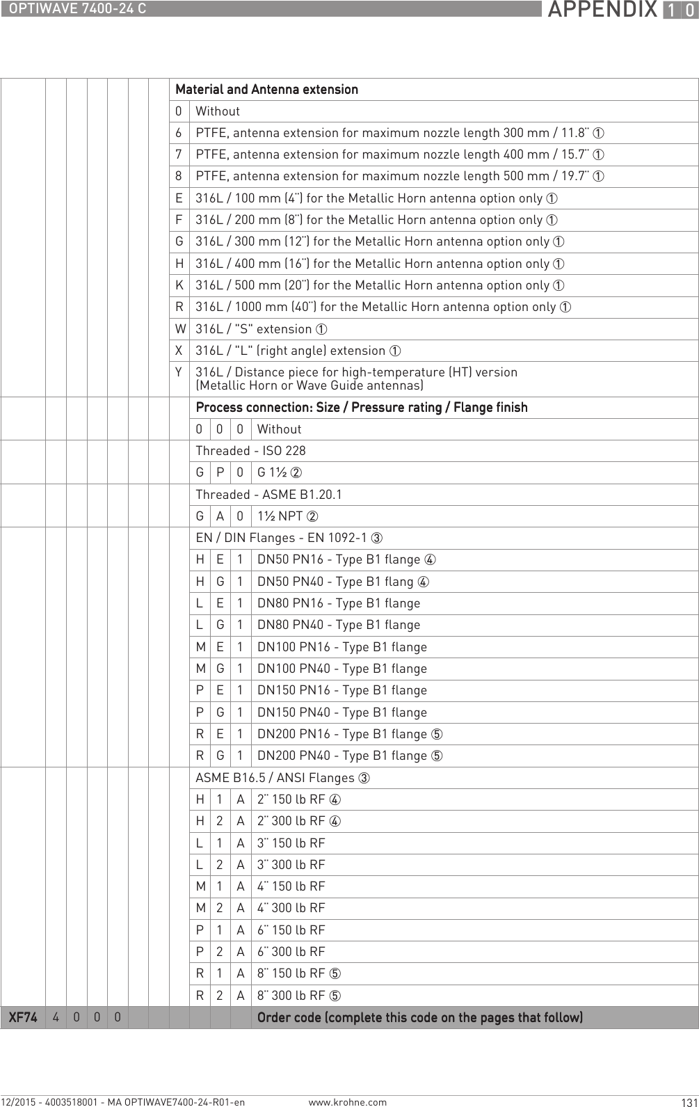
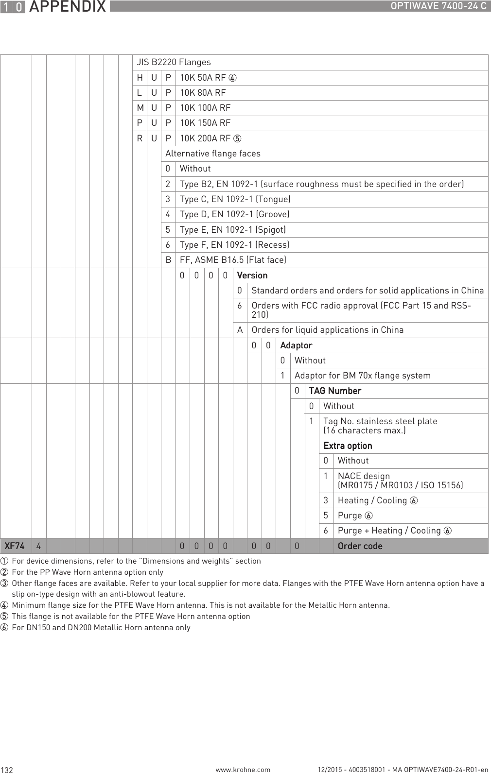
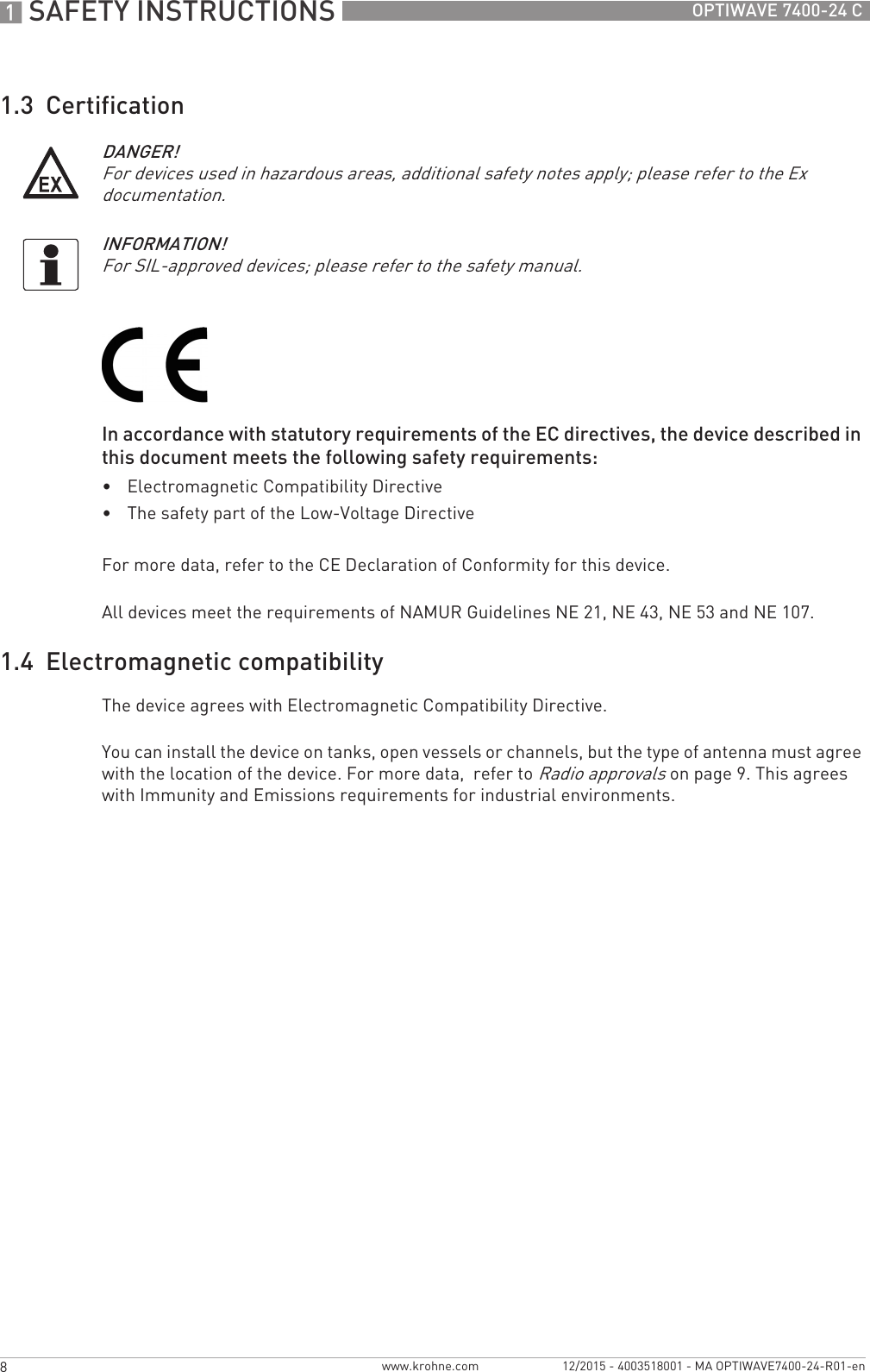
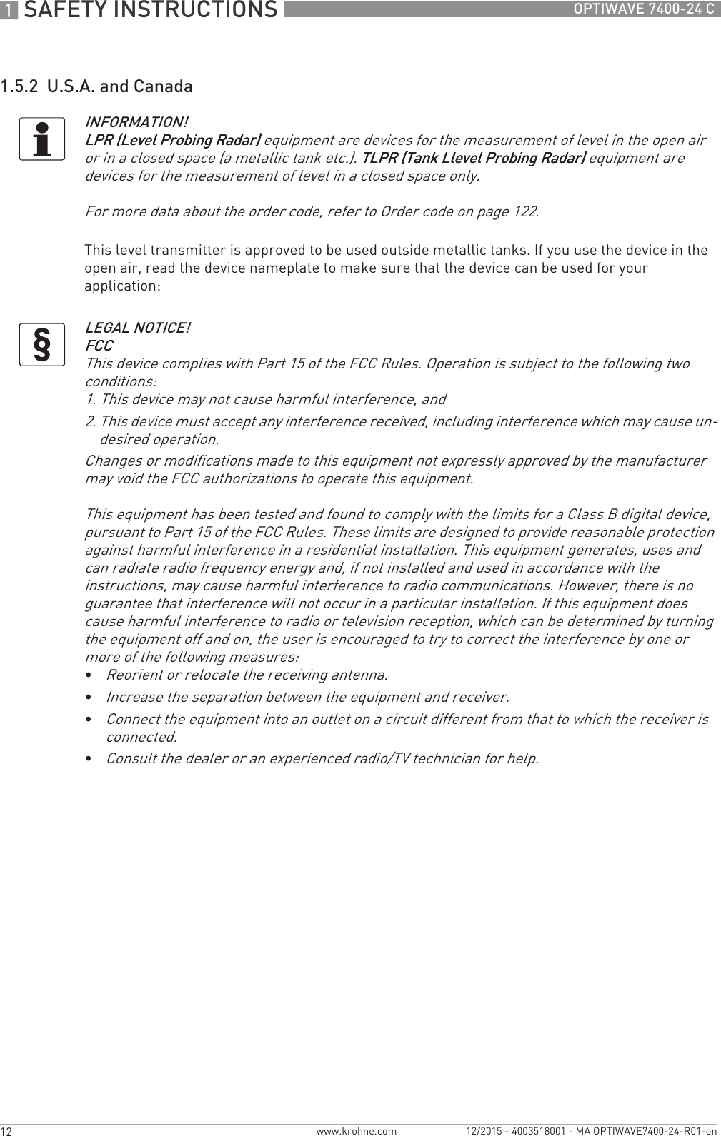
![10 APPENDIX 122 OPTIWAVE 7400-24 Cwww.krohne.com 12/2015 - 4003518001 - MA OPTIWAVE7400-24-R01-en10.1 Order codeMake a selection from each column to get the full order code. The characters of the order code highlighted in light grey describe the standard.VF74 4OPTIFLEX 7400 C 24 GHz Non-contact Radar (FMCW) level meter for liquidsOPTIFLEX 7400 C 24 GHz Non-contact Radar (FMCW) level meter for liquidsOPTIFLEX 7400 C 24 GHz Non-contact Radar (FMCW) level meter for liquidsOPTIFLEX 7400 C 24 GHz Non-contact Radar (FMCW) level meter for liquidsConverter version (Housing material Converter version (Housing material Converter version (Housing material Converter version (Housing material – Degrees of protection [IP code]) Degrees of protection [IP code]) Degrees of protection [IP code]) Degrees of protection [IP code])1OPTIWAVE 7400 C: Compact version (Aluminium – IP 66/67)2OPTIWAVE 7400 C: Compact version (Stainless steel – IP 66/67)3OPTIWAVE 7400 F: Remote version (converter and antenna housing: Aluminium – IP 66/67)4OPTIWAVE 7400 F: Remote version (converter and antenna housing: Stainless steel – IP 66/67)5OPTIWAVE 7400 F: Remote version (converter housing: Aluminium – IP 66/67 + antenna housing: Stainless steel – IP 66/67)ApprovalApprovalApprovalApproval0Without1ATEX Ex ia IIC T2…T6 + DIP 12ATEX Ex d ia IIC T2..T6 + DIP 13ATEX Ex ic IIC T2…T6 + DIP 16IECEx Ex ia IIC T2…T6 + DIP 17IECEx Ex d ia IIC T2…T6 + DIP 18IECEx Ex ic IIC T2…T6 + DIP 1AcFMus IS CL I/II/III, DIV 1, GPS A-G; CL I, Zone 0/20, Ex ia IIC/IIIC T2…T6BcFMus XP-IS/DIP CL I/II/III, DIV 1, GPS A-G (A not for CAN); CL I, Zone 0/20, Ex d/tb IIC/IIIC T2…T6CcFMus NI CL I/II/III, DIV 2, GPS A-G; CL I, Zone 2, Ex nA IIC T2...T6LNEPSI Ex ia IIC T2 ~ T6 + DIP 1MNEPSI Ex d ia IIC T2 ~ T6 + DIP 1NNEPSI Ex ic IIC T2 ~ T6 + DIP 1Other approvalOther approvalOther approvalOther approval0Without1SIL 2 – only available with 4…20 mA output4CRN (Canadian Registration Number)5CRN + SIL 2 – only available with 4…20 mA outputVF74VF74VF74VF74 4Order code (complete this code on the pages that follow)Order code (complete this code on the pages that follow)Order code (complete this code on the pages that follow)Order code (complete this code on the pages that follow)](https://usermanual.wiki/KROHNE/FMCW24G74L.Manual-English/User-Guide-2872319-Page-122.png)