KROHNE FMCW80G74TA Tank Level Probing Radar User Manual HB OPTIWAVE7500 en 161026 4004375401 R01
KROHNE Tank Level Probing Radar HB OPTIWAVE7500 en 161026 4004375401 R01
UserManual.wiki
>
KROHNE
>
FMCW80G74TA User Manual
manual
Navigation menu
Upload a User Manual
Namespaces
Wiki Guide
HTML
PDF
Info
Views
User Manual
Discussion / Help
Navigation

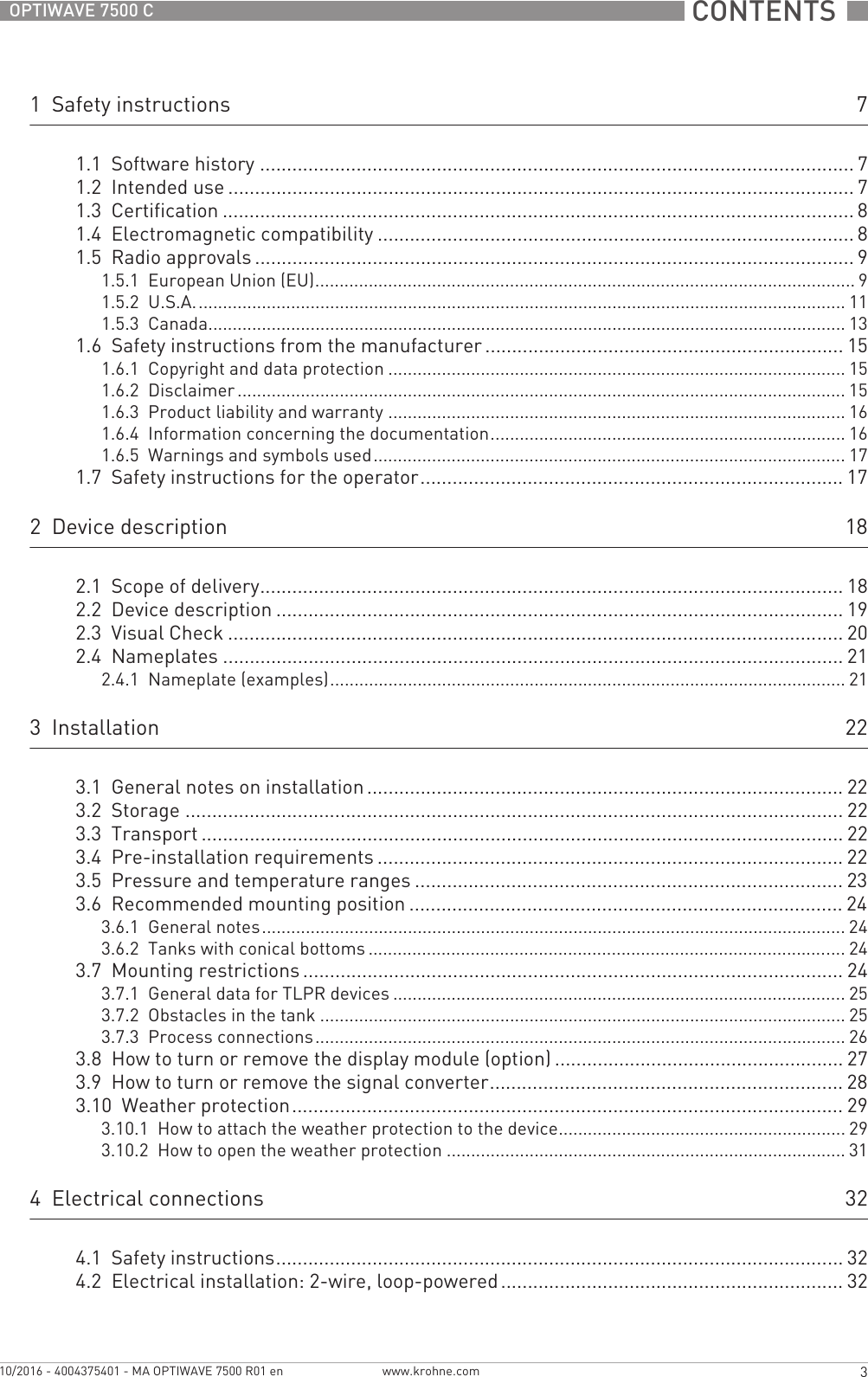

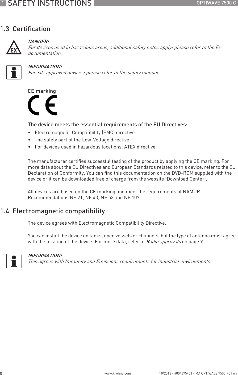
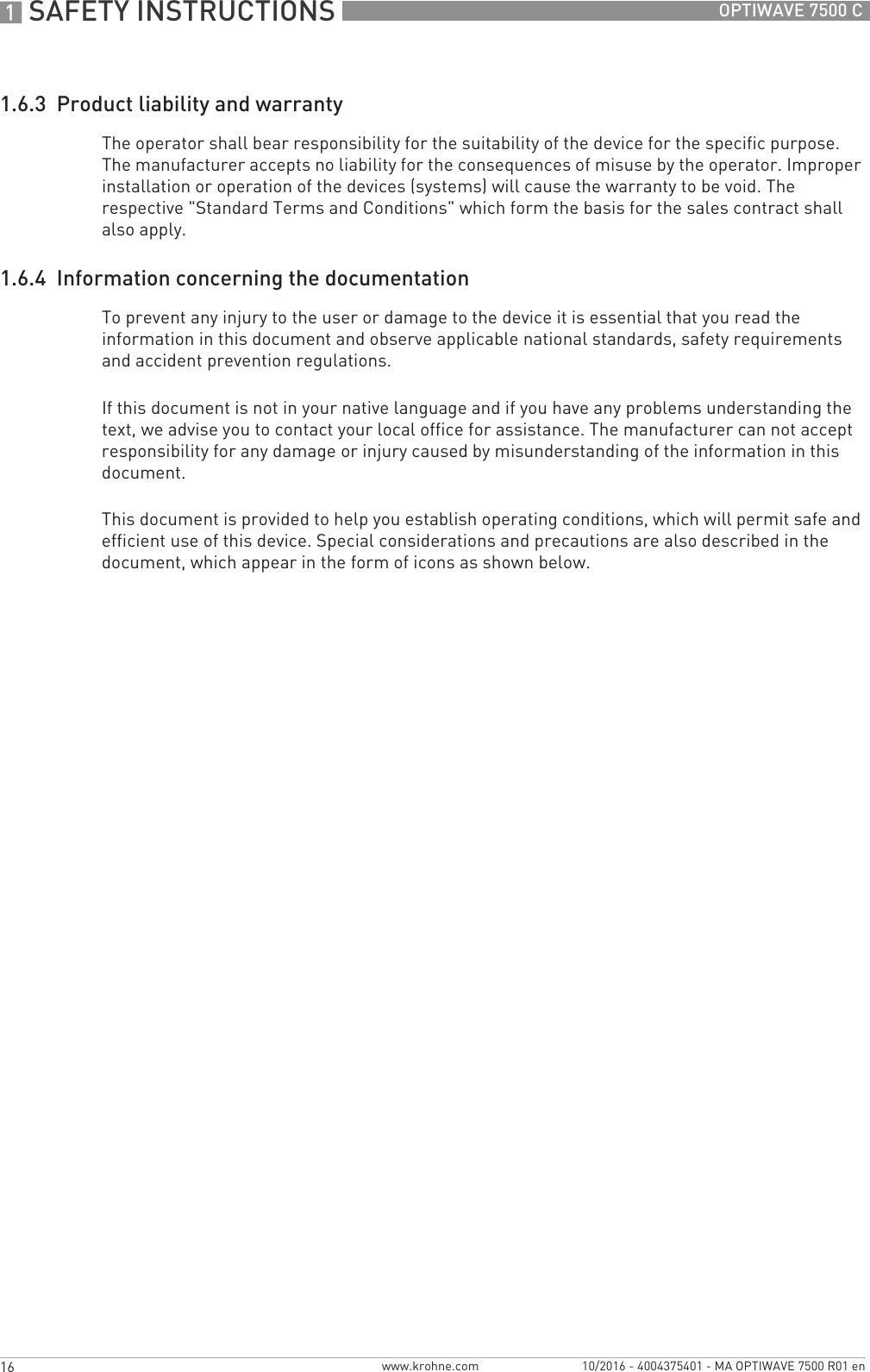
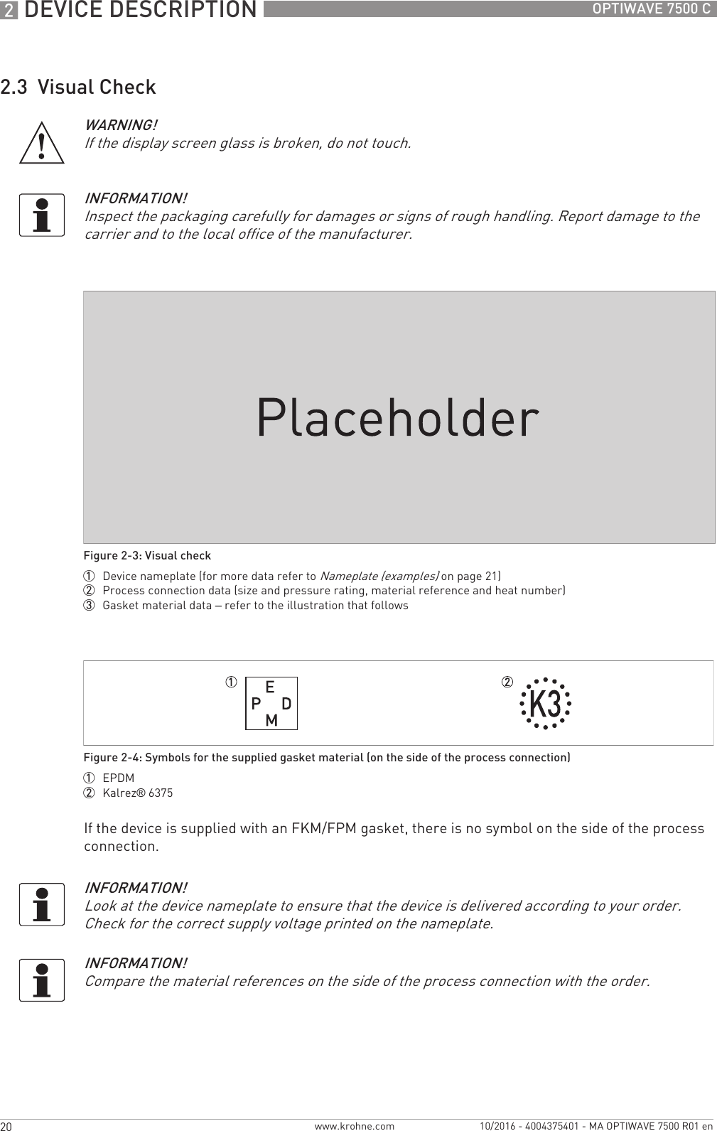
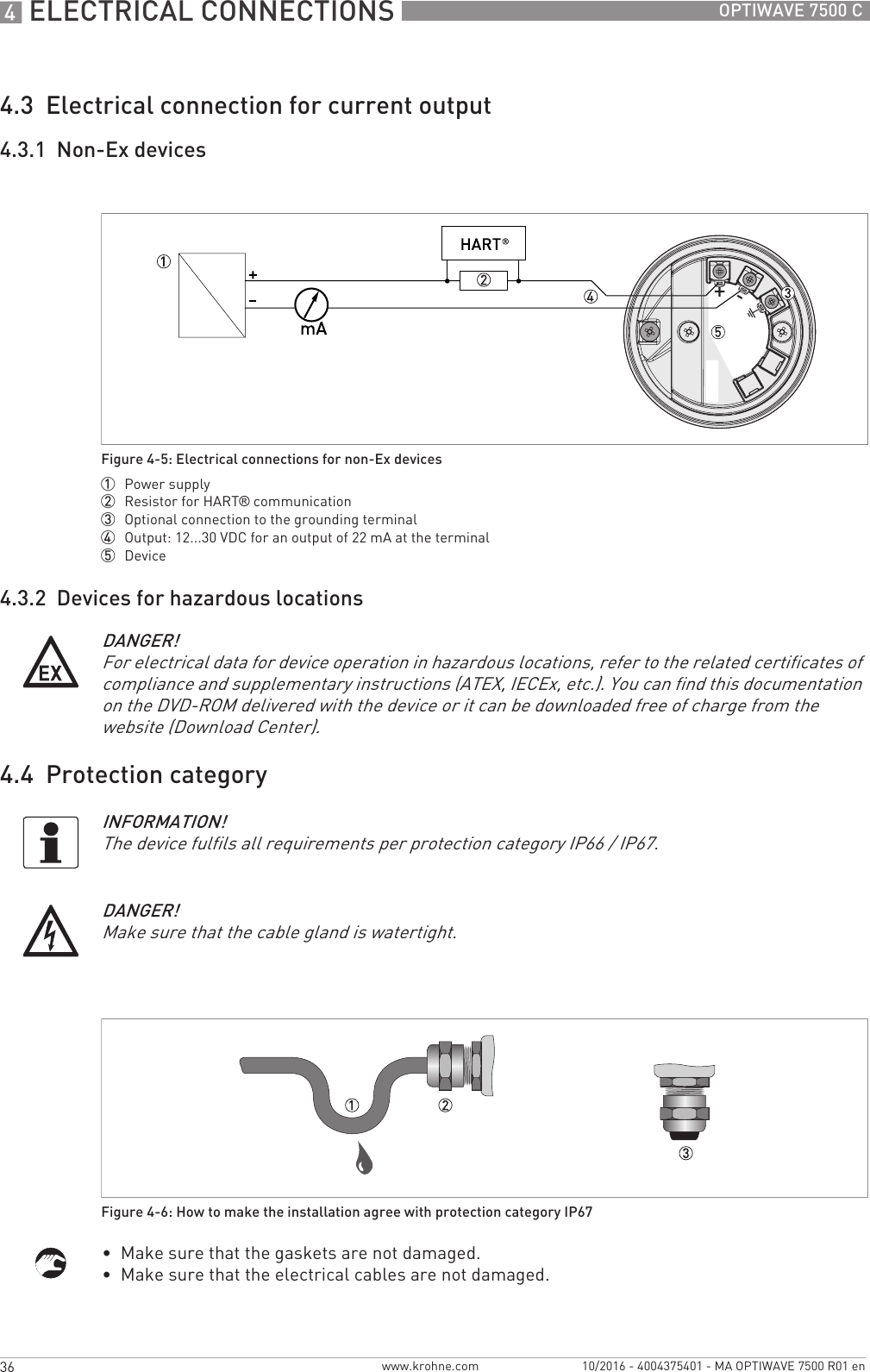
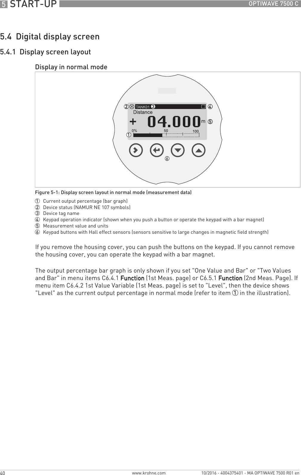
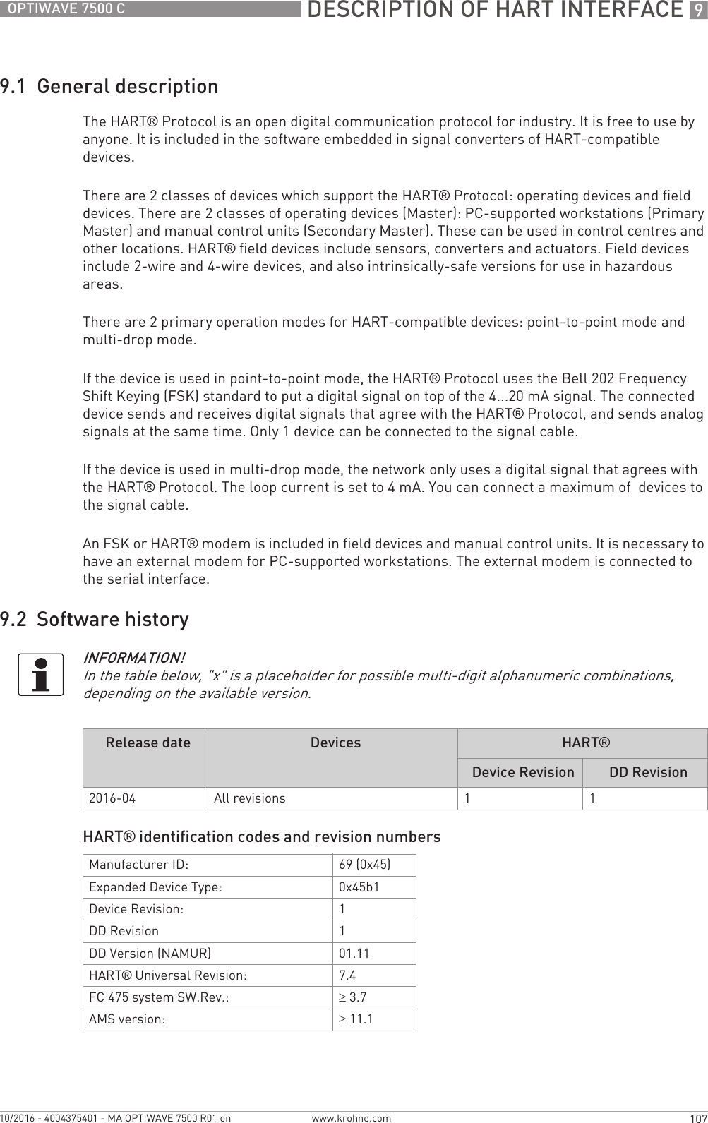
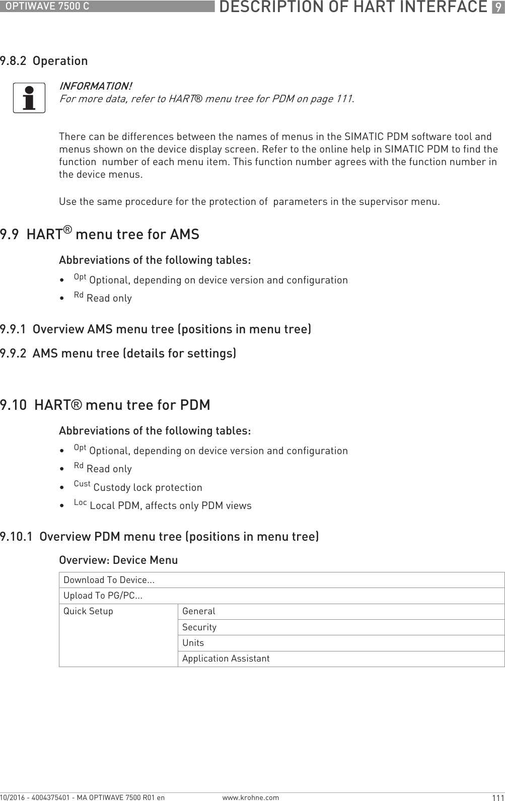
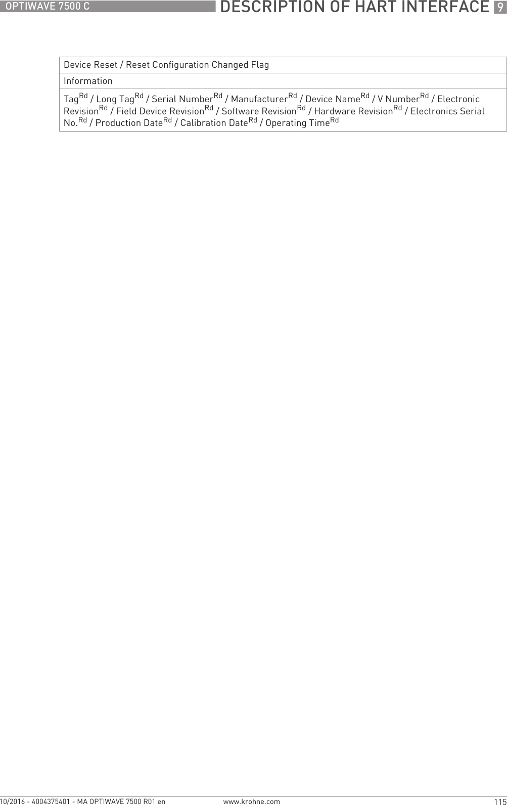
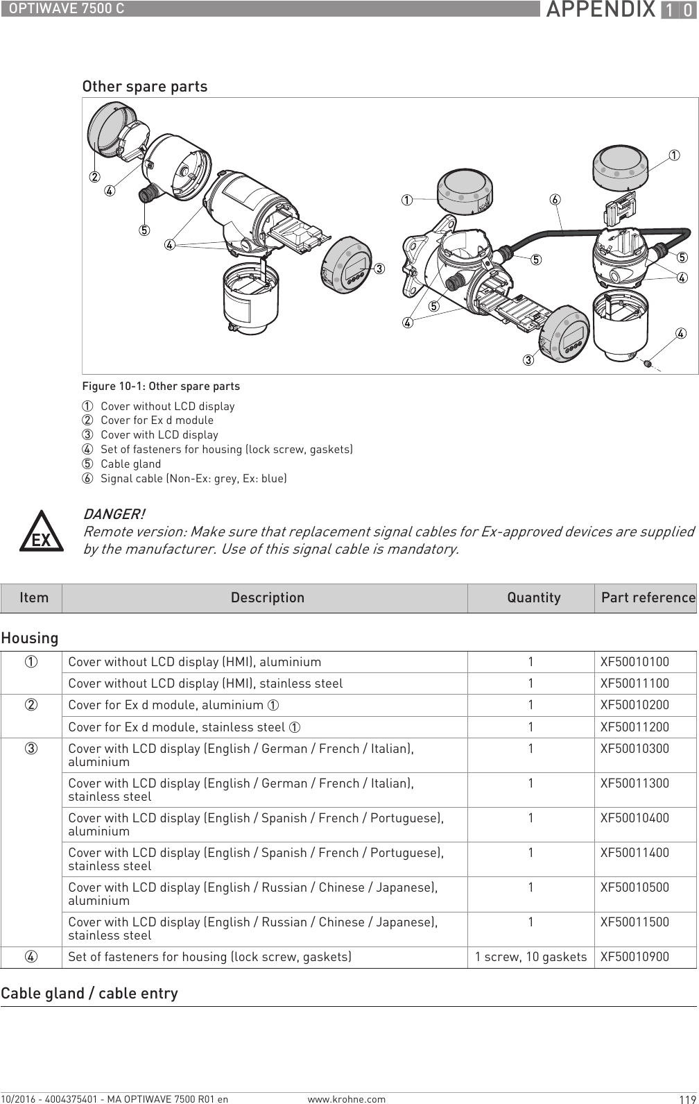
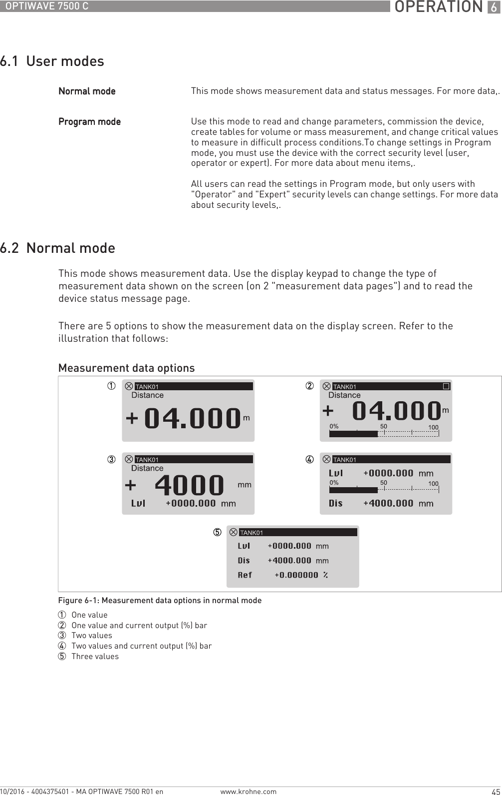
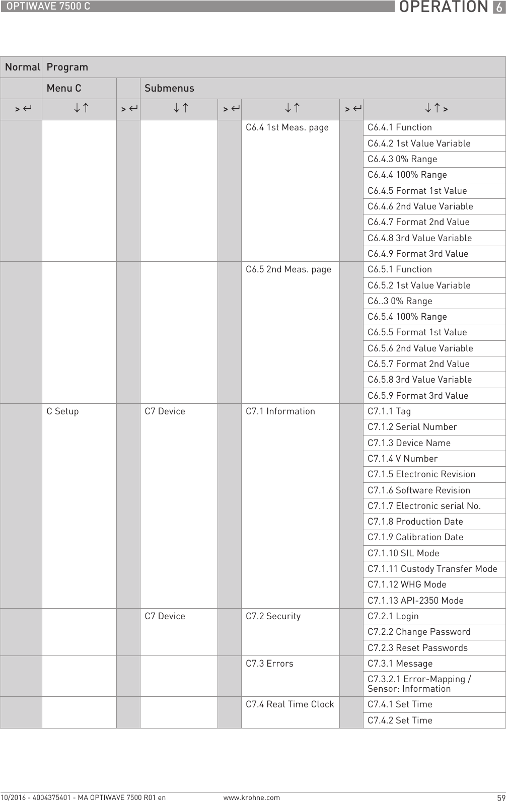
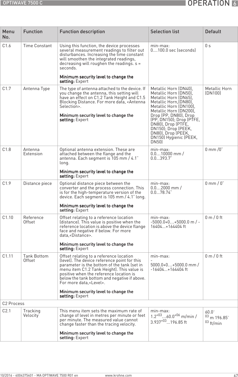
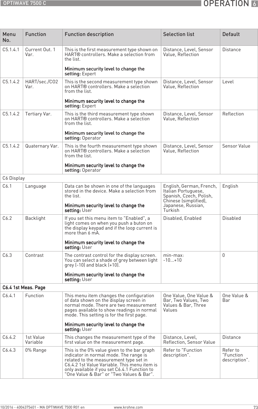
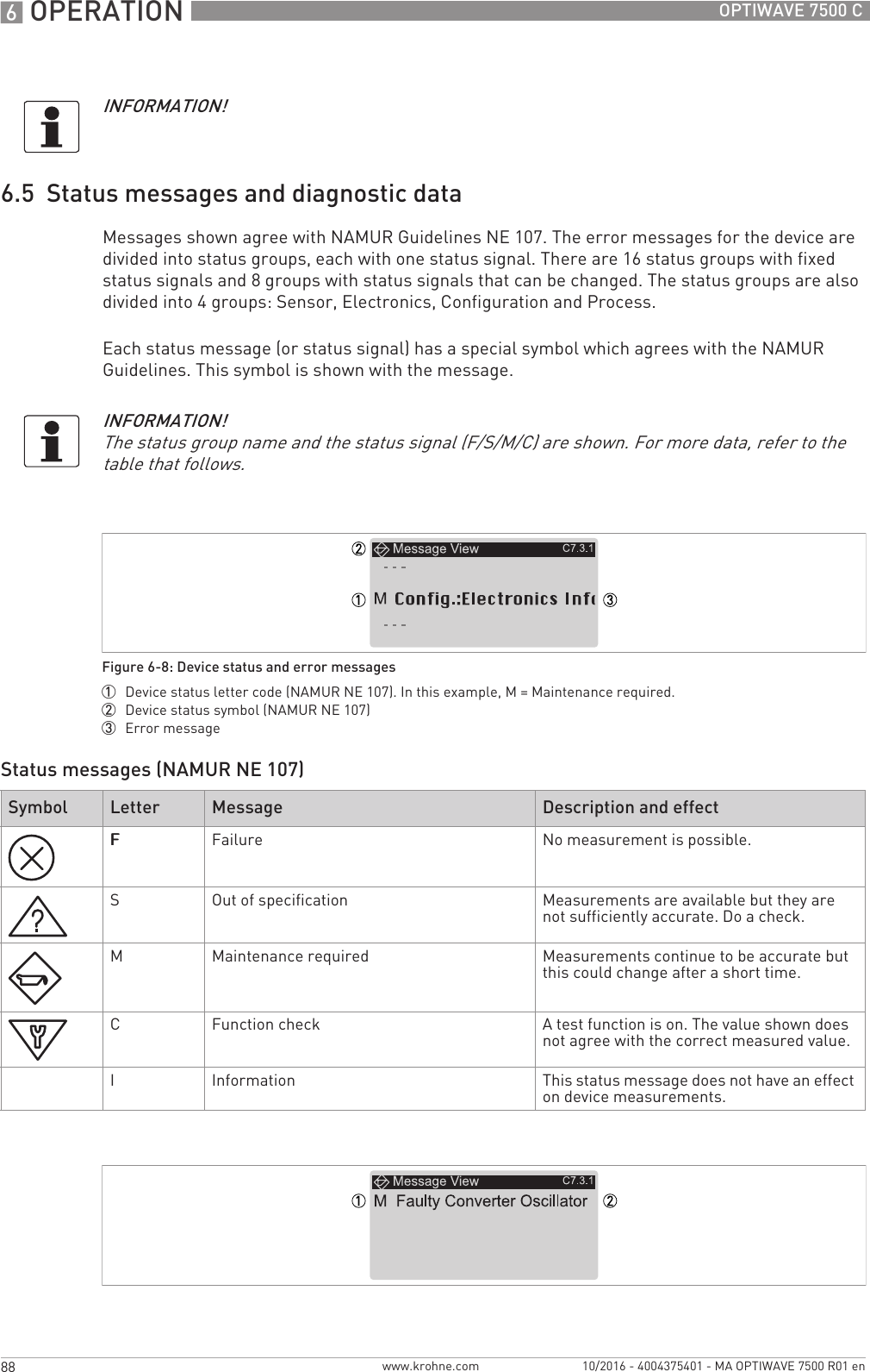
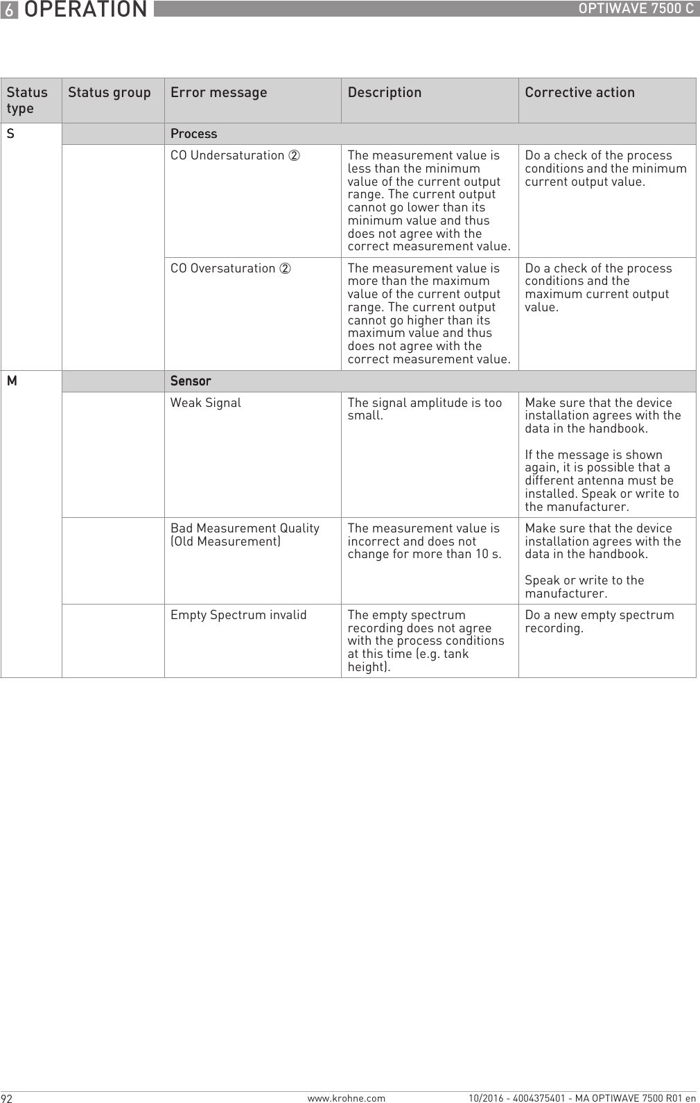
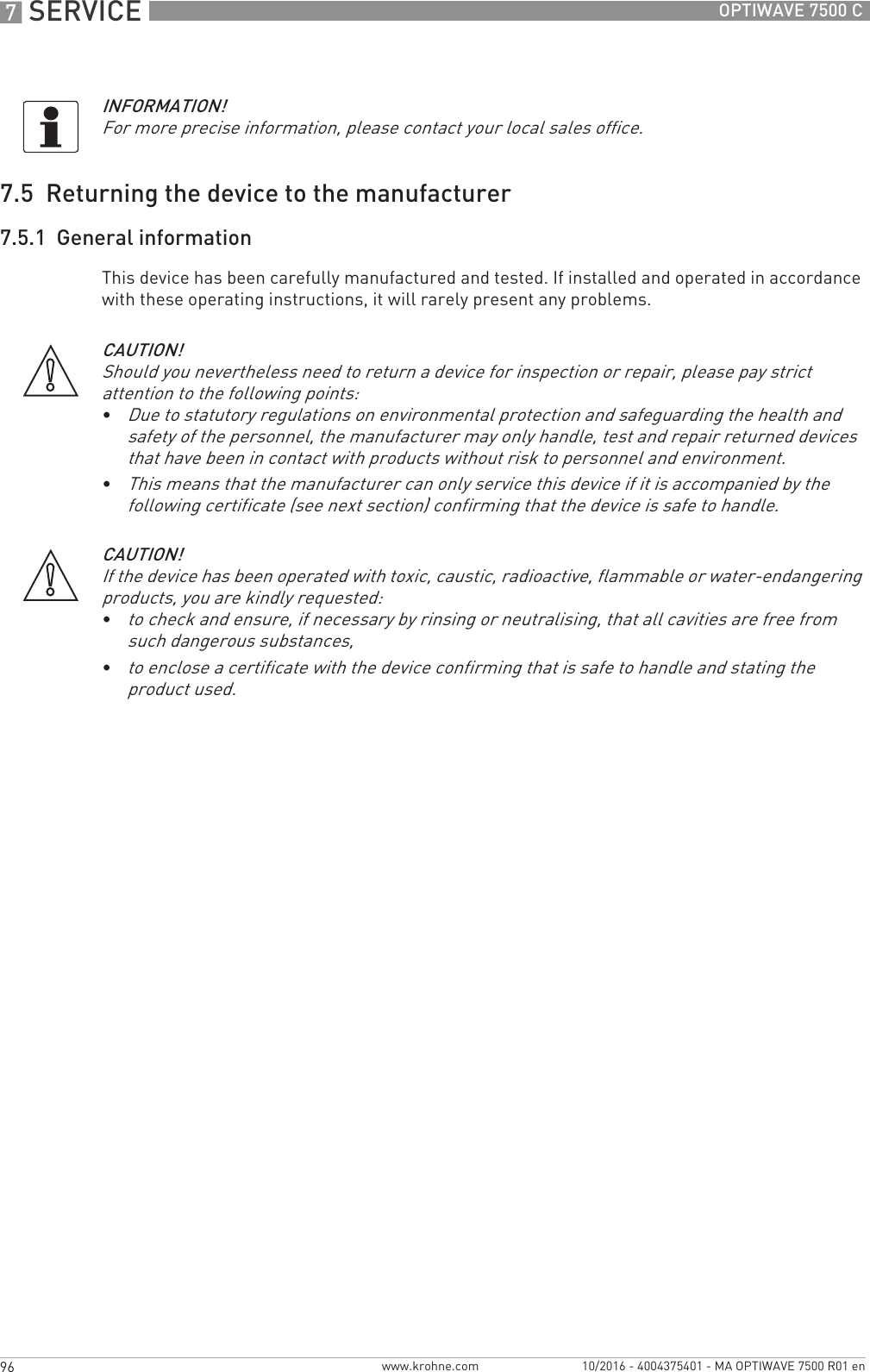
![START-UP 541OPTIWAVE 7500 Cwww.krohne.com10/2016 - 4004375401 - MA OPTIWAVE 7500 R01 en5.4.2 Keypad buttonsFunctions of keypad buttonsFor more data on keypad functions,.Display in program modeFigure 5-2: Display screen layout in program mode1 Menu number or menu item number2 Location (menu) of sub-menu or menu item3 Menu item nameKeypad button Symbol Function [Right] [>>>>] Normal mode:Normal mode:Normal mode:Normal mode: Enter Program modeConfiguration mode:Configuration mode:Configuration mode:Configuration mode:Menu:Menu:Menu:Menu: Enter the sub-menu or menu itemMenu item:Menu item:Menu item:Menu item: Move cursor one digit to the right (this includes the decimal point). If the cursor is on the last digit, a push of this button will move the cursor to the first digit. [Return / Escape] [^^^^]Normal mode:Normal mode:Normal mode:Normal mode: NoneConfiguration mode:Configuration mode:Configuration mode:Configuration mode:Menu:Menu:Menu:Menu: Exit the menu. If you are in the top level menu (R), the device goes back to normal mode.Menu item:Menu item:Menu item:Menu item: Exit the menu item. [Down] []Normal mode:Normal mode:Normal mode:Normal mode: Change screen (measurement pages 1 and 2 and the status message page)Configuration mode:Configuration mode:Configuration mode:Configuration mode: Decrease value or change parameter [Up] []Normal mode:Normal mode:Normal mode:Normal mode: Change screen (measurement pages 1 and 2 and the status message page)Configuration mode:Configuration mode:Configuration mode:Configuration mode: Increase value or change parameter](https://usermanual.wiki/KROHNE/FMCW80G74TA/User-Guide-3267690-Page-41.png)
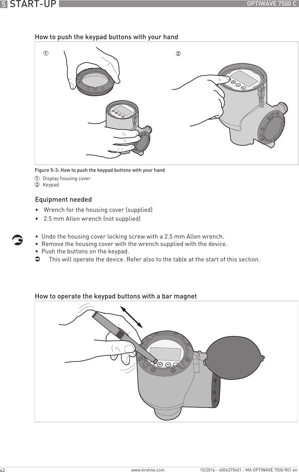
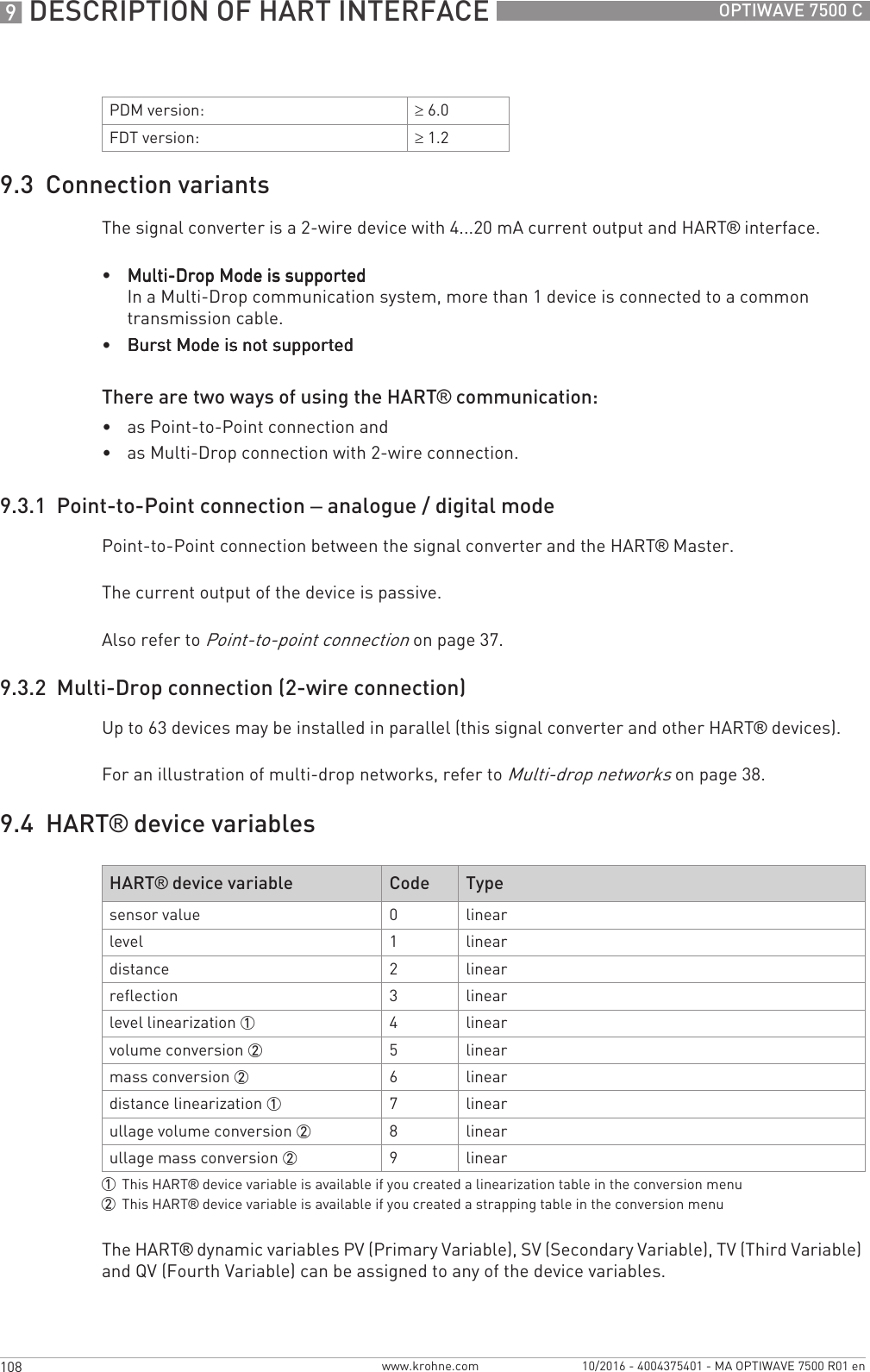
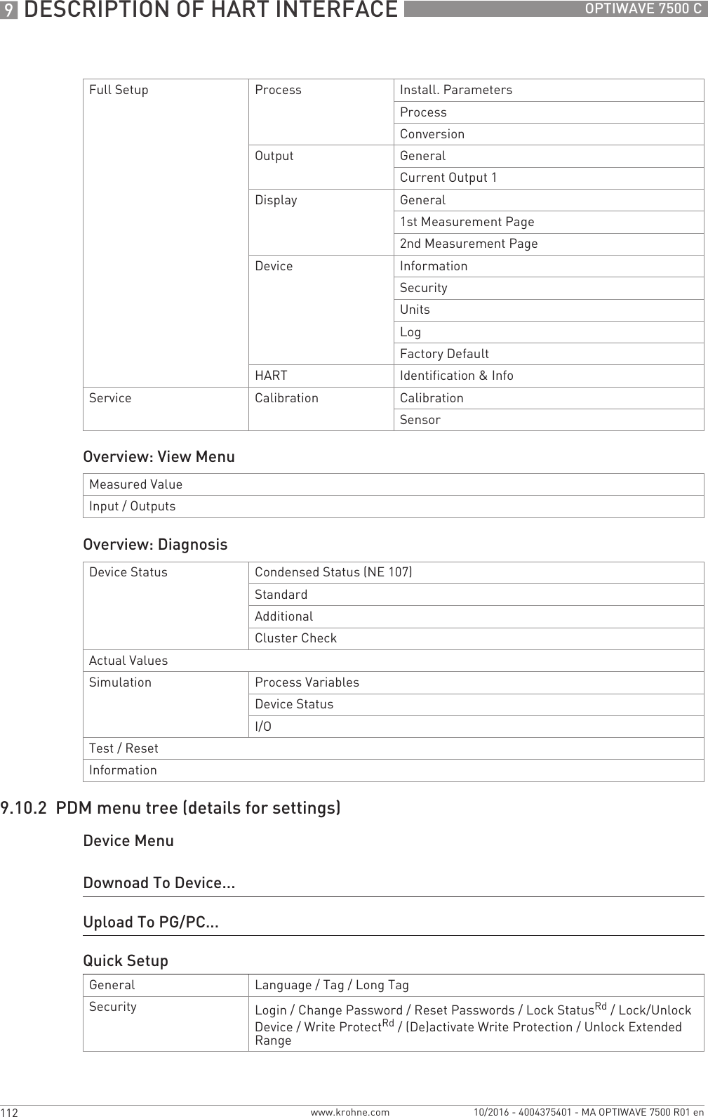
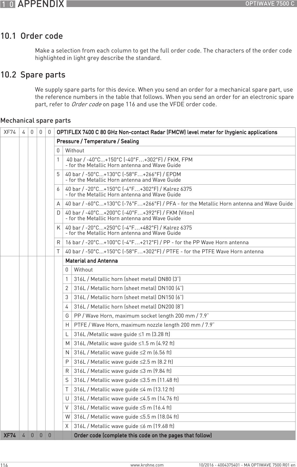
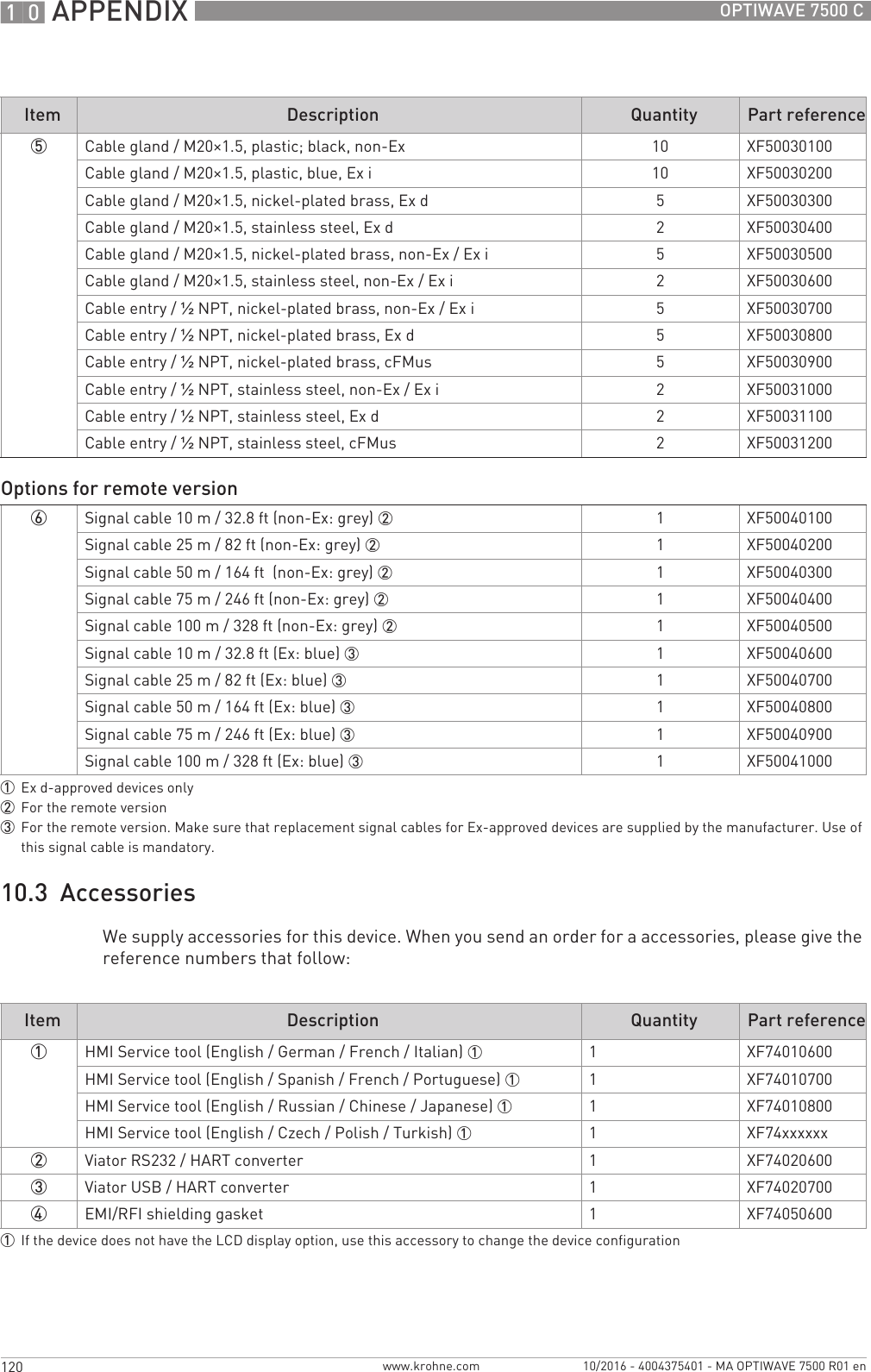
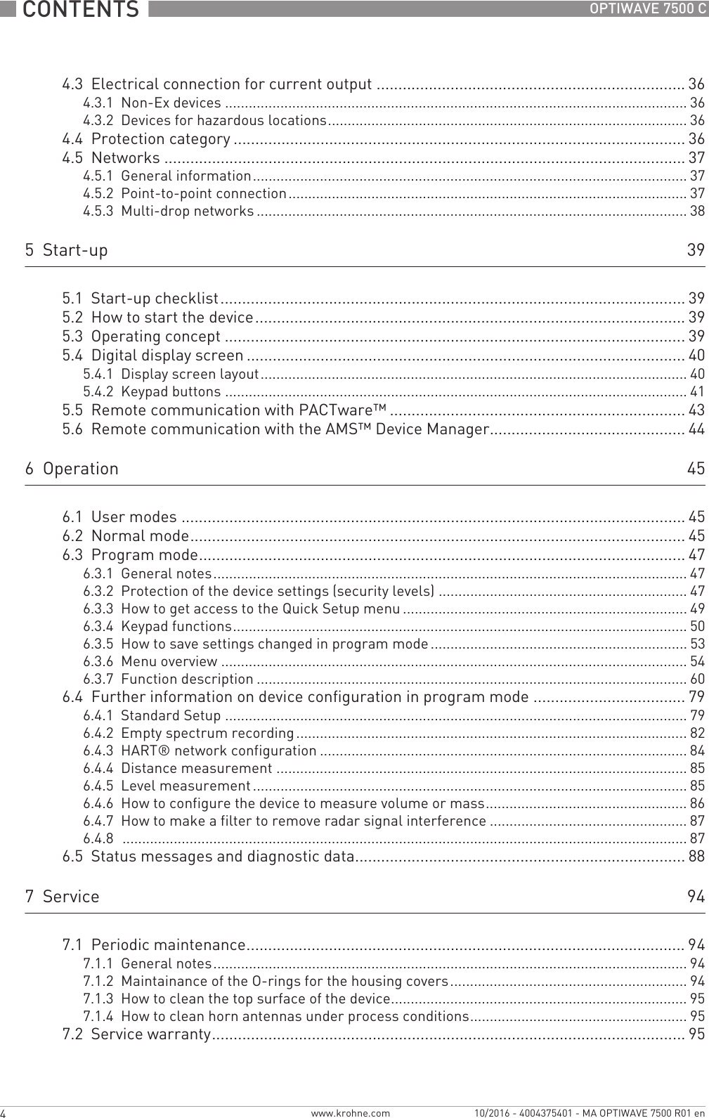
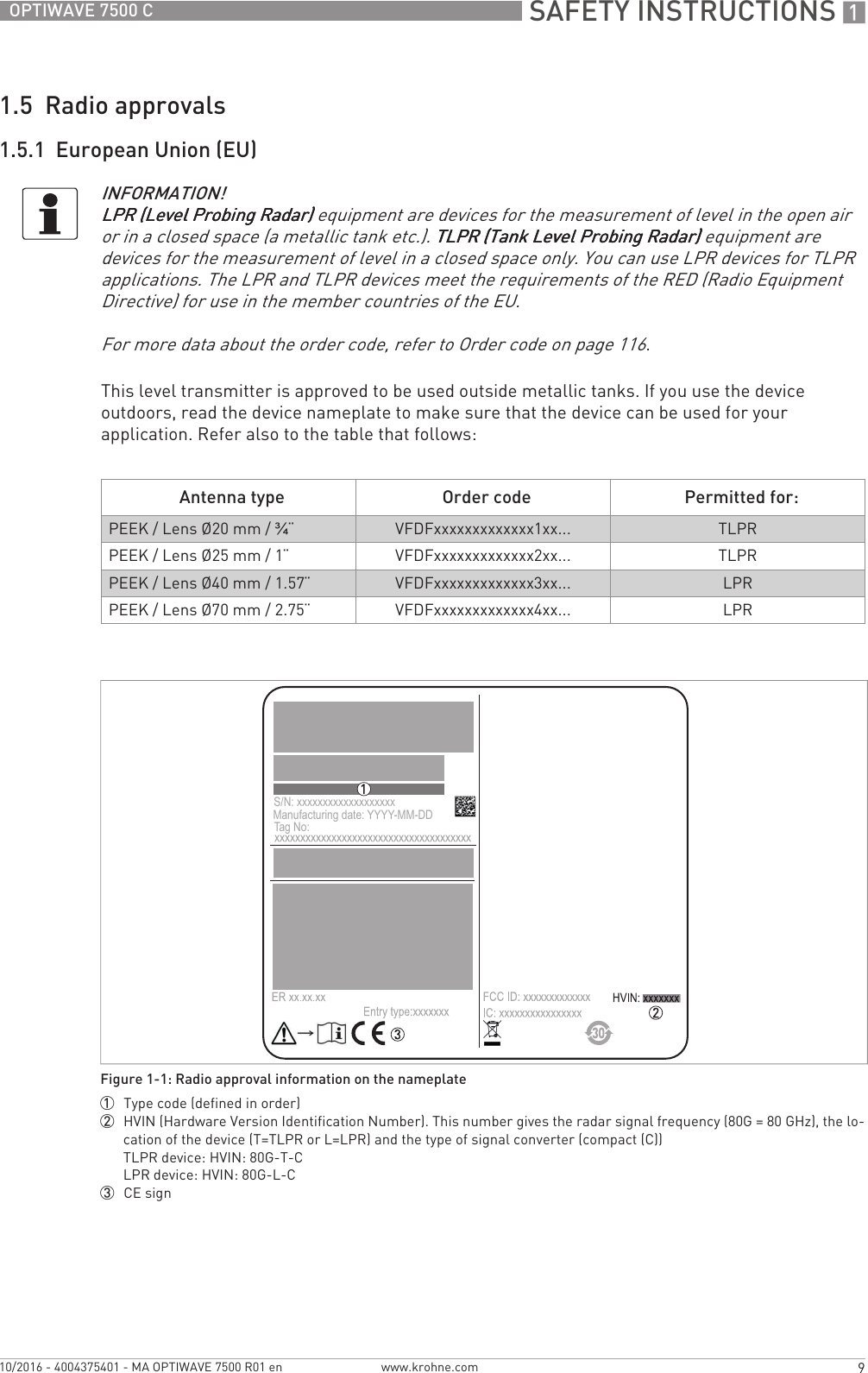
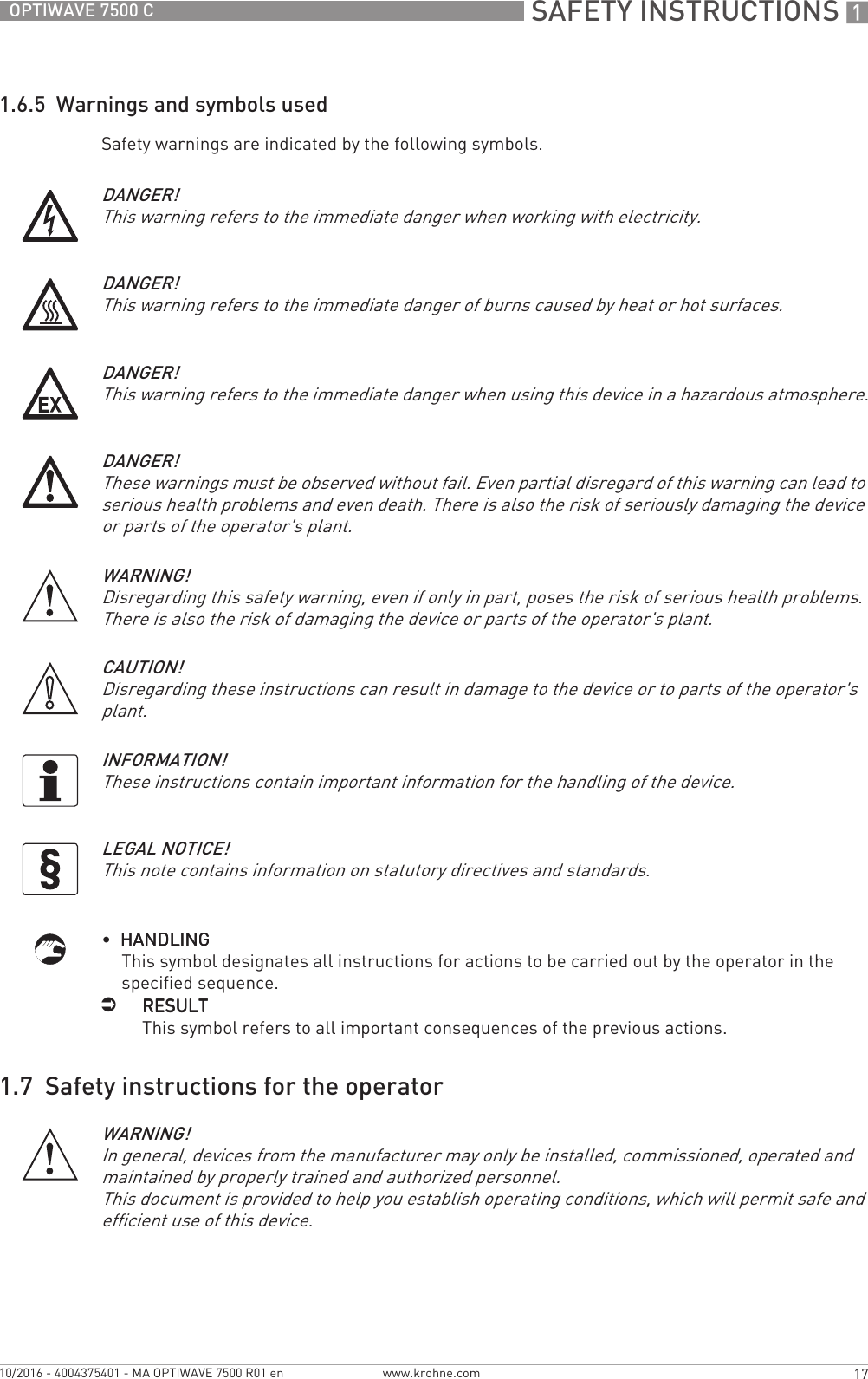
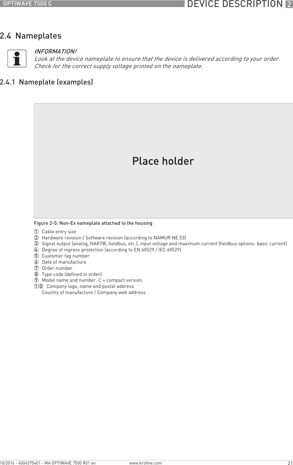
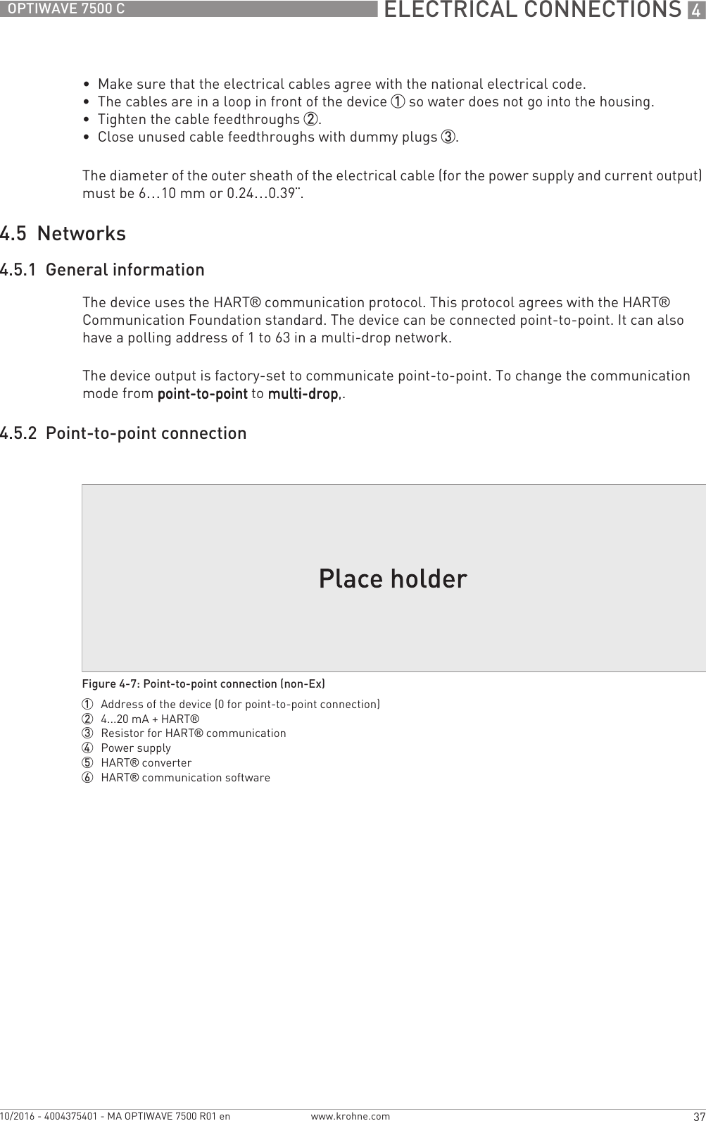
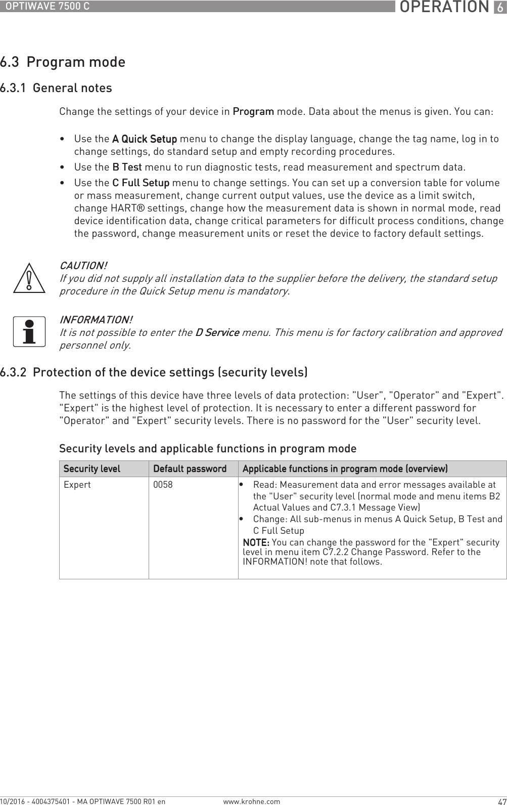
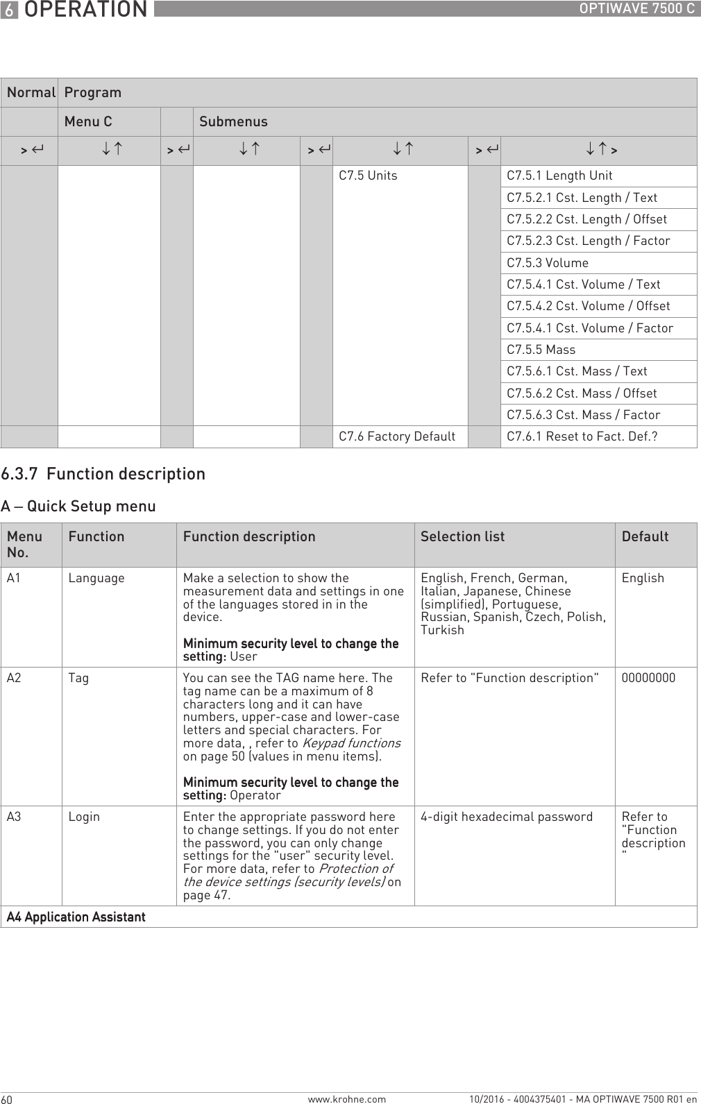
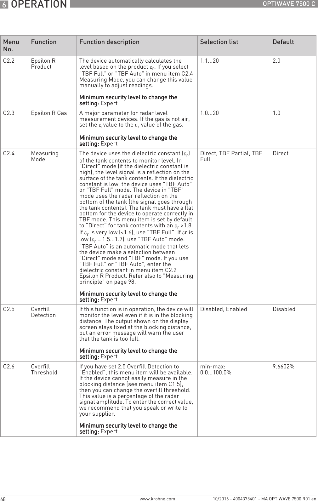
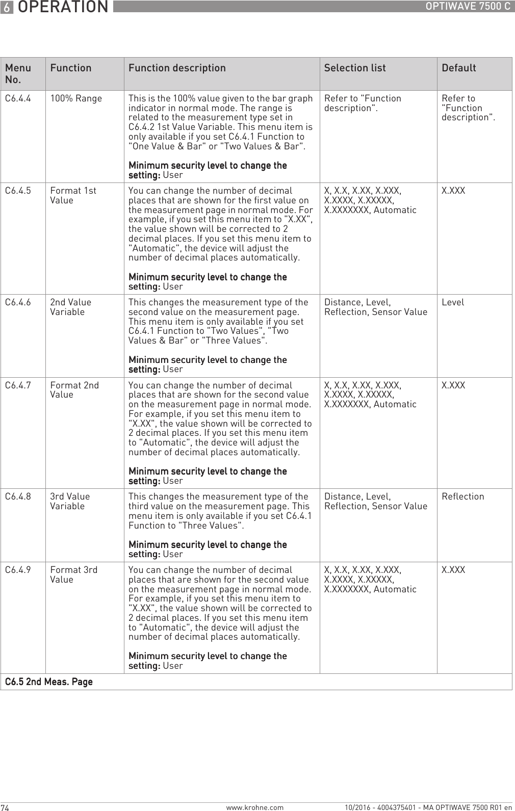
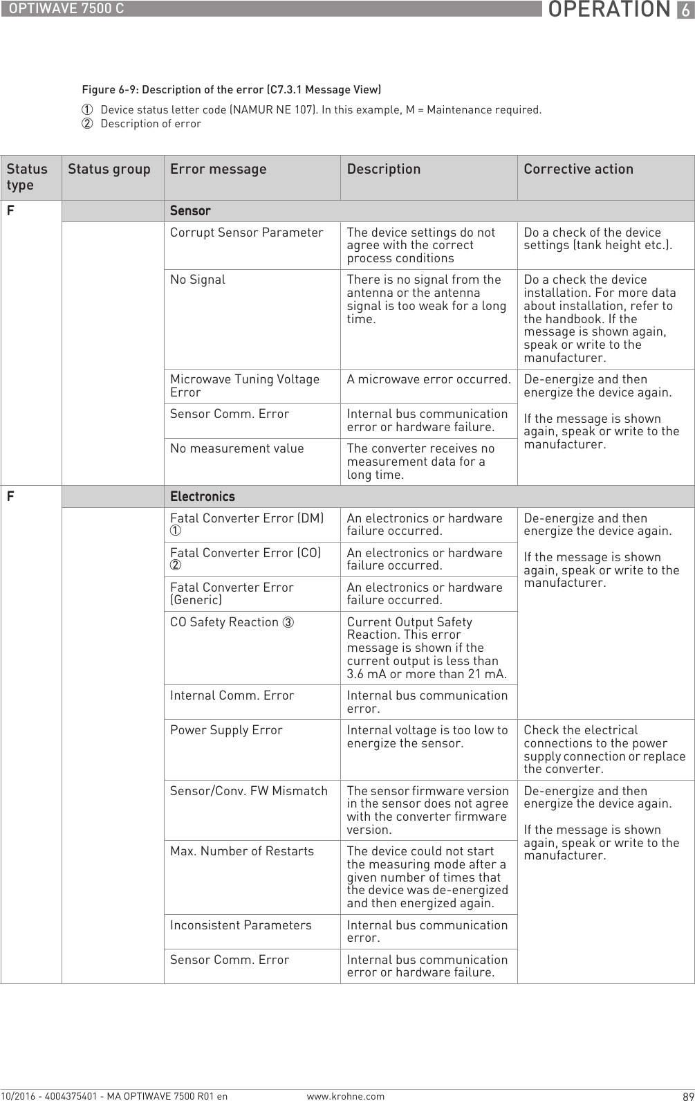
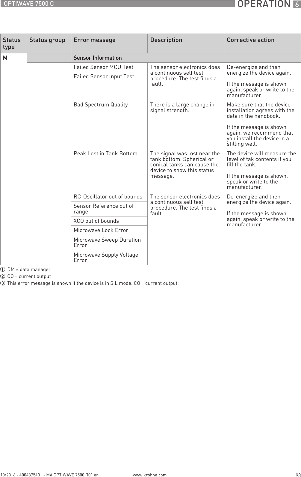
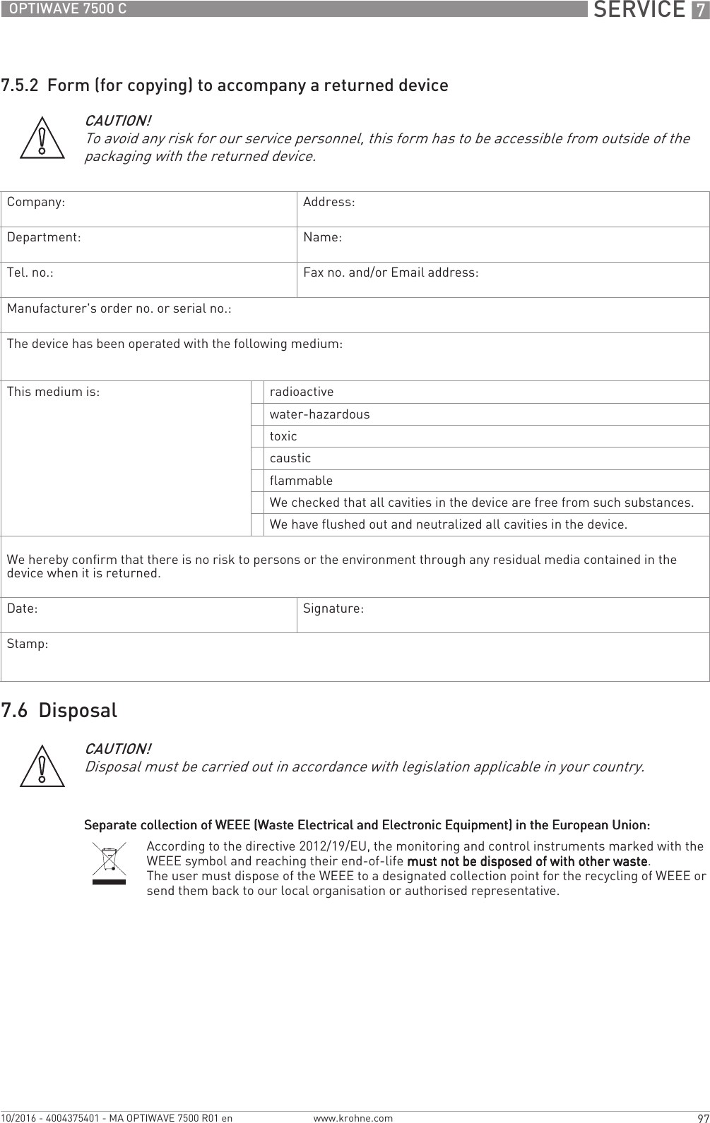
![6 OPERATION 46 OPTIWAVE 7500 Cwww.krohne.com 10/2016 - 4004375401 - MA OPTIWAVE 7500 R01 enMeasurement data includes different measurement types (level, distance volume, ullage volume, mass etc.). Some measurement tyypes will only be available if you entered the correct parameters in Program mode.In this example, the device measures a distance of 10 m, but C7.5.1 Length Unit is set to mm and menu C6.4.5 Format 1st Value is set to X.XXXX (five digits with four decimal places). This is not sufficient to measure 10 m.You can change the number of digits and decimal places in the measurement values shown in normal mode.Volume measurementYou must make a conversion table (strapping table) to show measurement data as a volume or a mass. Go to C3.2 Input table (Full Setup > ConversionFull Setup > ConversionFull Setup > ConversionFull Setup > Conversion) to make the strapping table. For more data,.Functions of keypad buttons (normal mode)INFORMATION!Go to C6.4.1 FunctionFunctionFunctionFunction or C6.5.1 Function Function Function Function (Full Setup > Display > 1st Measur. PageFull Setup > Display > 1st Measur. PageFull Setup > Display > 1st Measur. PageFull Setup > Display > 1st Measur. Page or Full Setup > Full Setup > Full Setup > Full Setup > Display > 2nd Measur. PageDisplay > 2nd Measur. PageDisplay > 2nd Measur. PageDisplay > 2nd Measur. Page) in Program mode to change the layout of the display screen.Users of all security levels can change this setting.Measurement data format errorsFigure 6-2: Error symbol: the number of digits and decimal places is not sufficient for the measurement data1 Error symbol: the number of digits and decimal places is not sufficient for the measurement data. It is possible that the length units must be changed from "mm" to "m".INFORMATION!Go to C6.4.5 Format 1st valueFormat 1st valueFormat 1st valueFormat 1st value, C6.4.7 Format 2nd valueFormat 2nd valueFormat 2nd valueFormat 2nd value, C6.4.9 Format 3rd valueFormat 3rd valueFormat 3rd valueFormat 3rd value, C6.5.5 Format Format Format Format 1st value1st value1st value1st value, C6.5.7 Format 2nd valueFormat 2nd valueFormat 2nd valueFormat 2nd value or C6.5.9 Format 3rd valueFormat 3rd valueFormat 3rd valueFormat 3rd value (Full Setup > Display > 1st Measur. Full Setup > Display > 1st Measur. Full Setup > Display > 1st Measur. Full Setup > Display > 1st Measur. PagePagePagePage or Full Setup > Display > 2nd Measur. PageFull Setup > Display > 2nd Measur. PageFull Setup > Display > 2nd Measur. PageFull Setup > Display > 2nd Measur. Page) in Program mode to change the number of digits and decimal places. If there is a large change in a measurement value, set the related menu item to "Automatic".Keypad button Symbol Function [Right] [>>>>] Enter Program mode [Return / Escape] [^^^^]— [Down] []Change screen (measurement pages 1 and 2, and the status message page) [Up] []Change screen (measurement pages 1 and 2 and the status message page)](https://usermanual.wiki/KROHNE/FMCW80G74TA/User-Guide-3267690-Page-46.png)
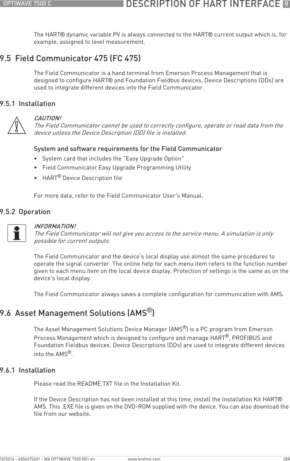
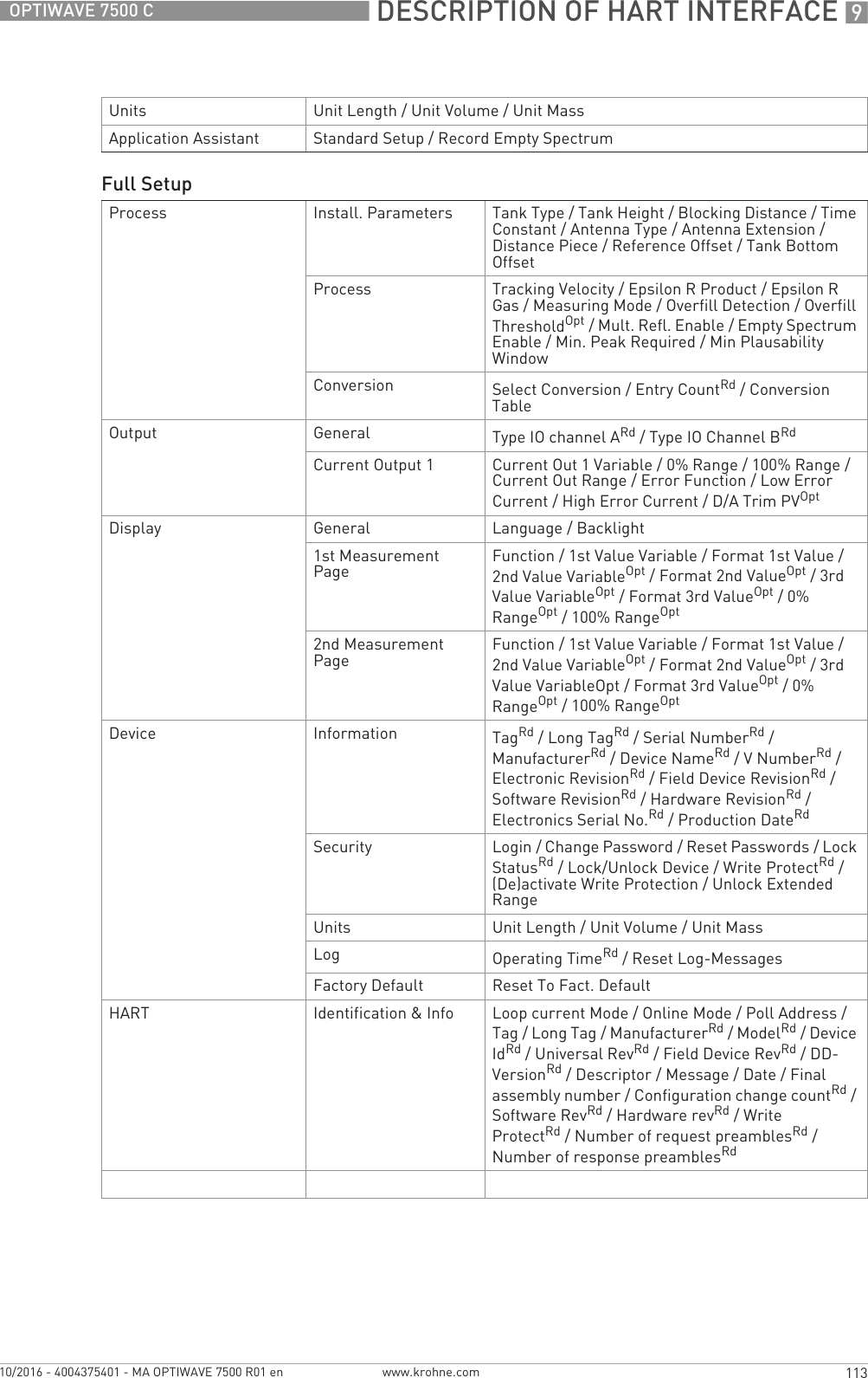
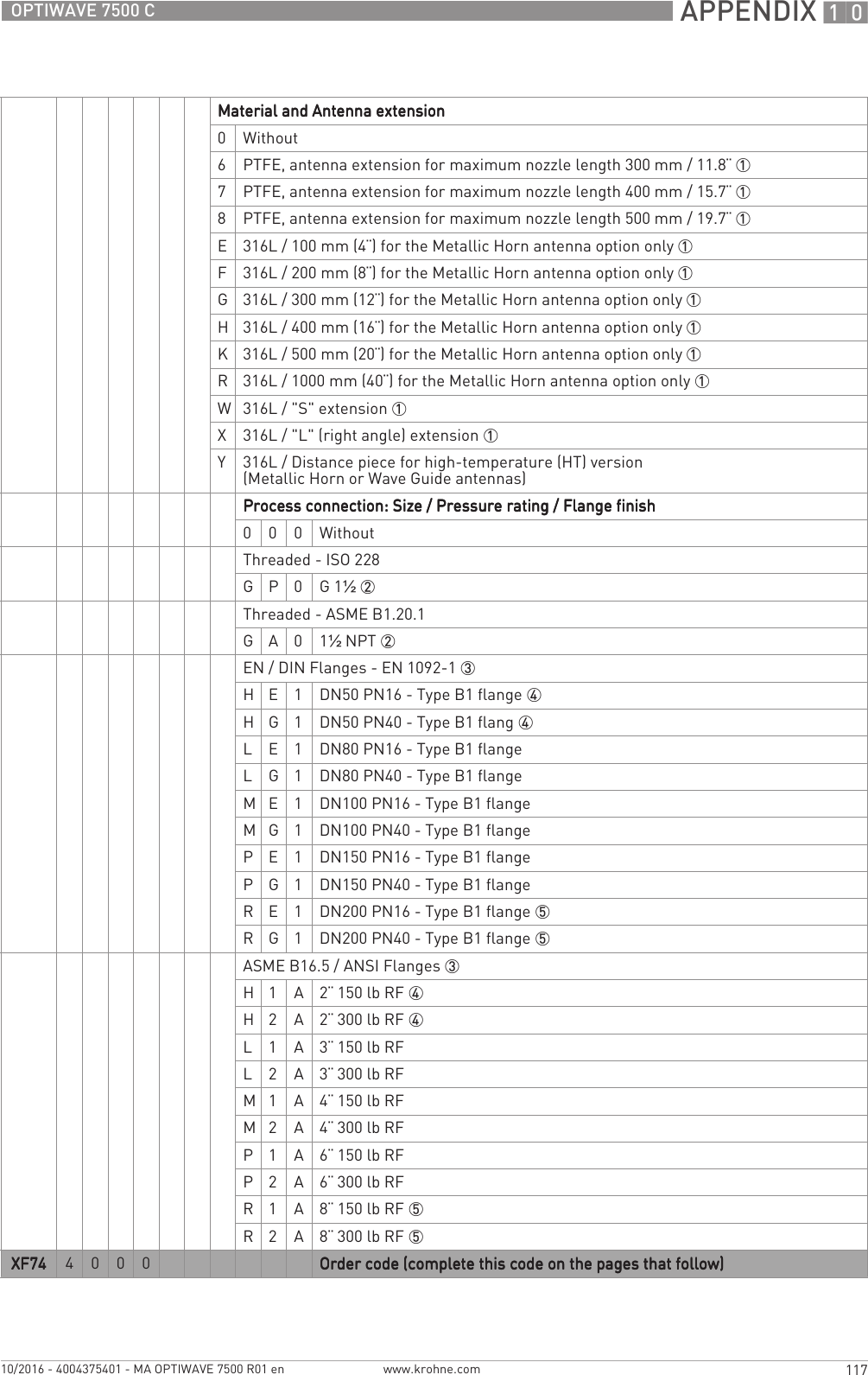
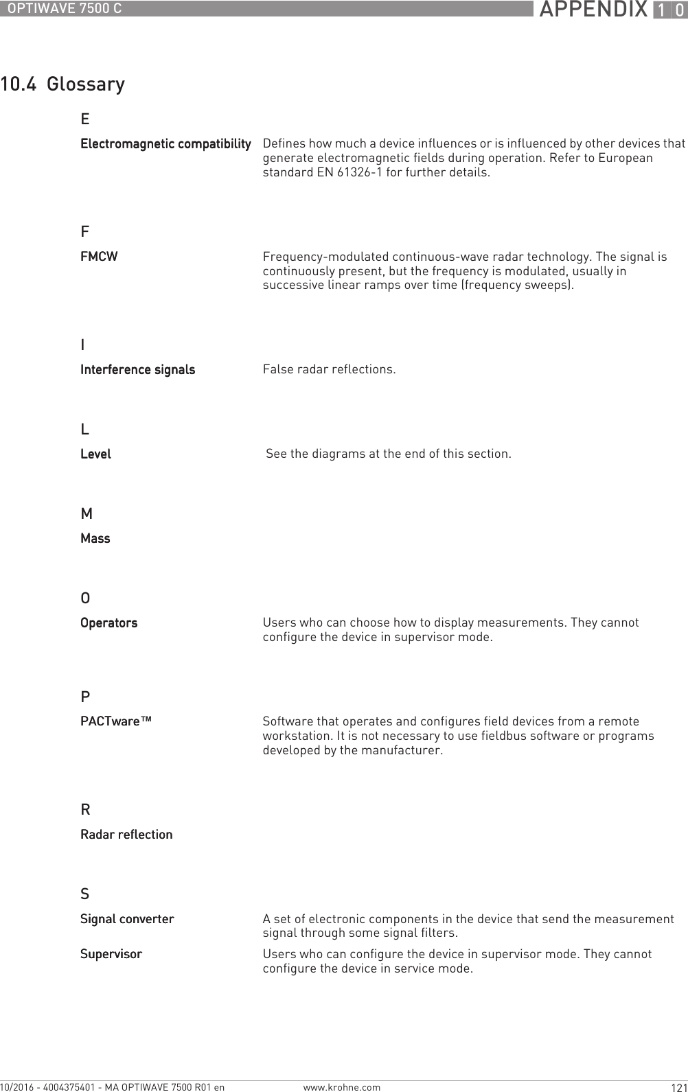
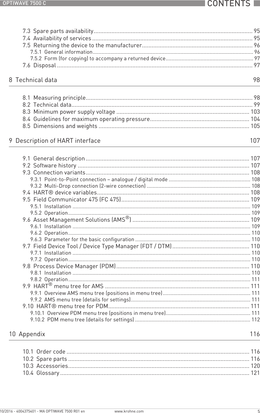
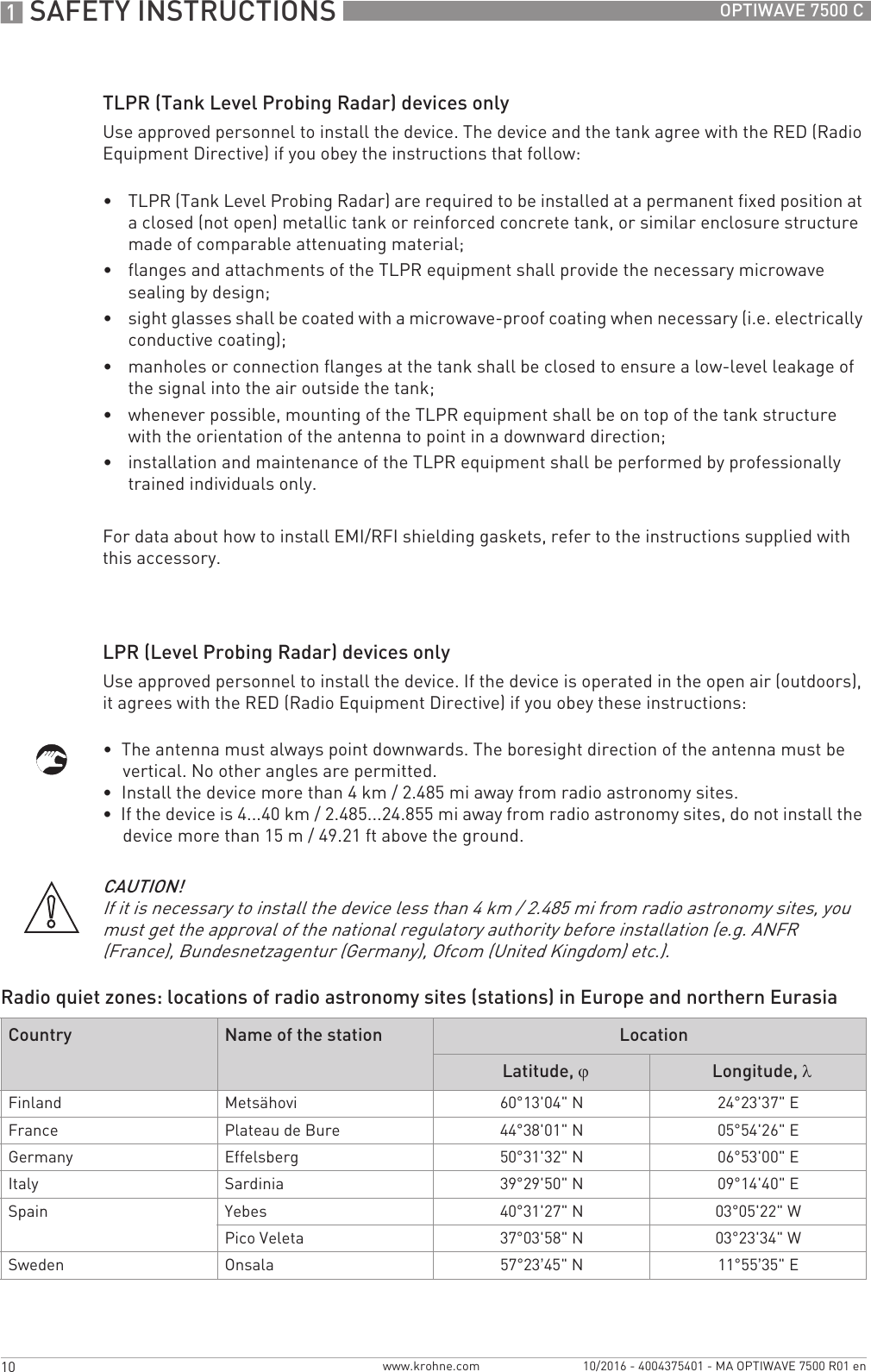
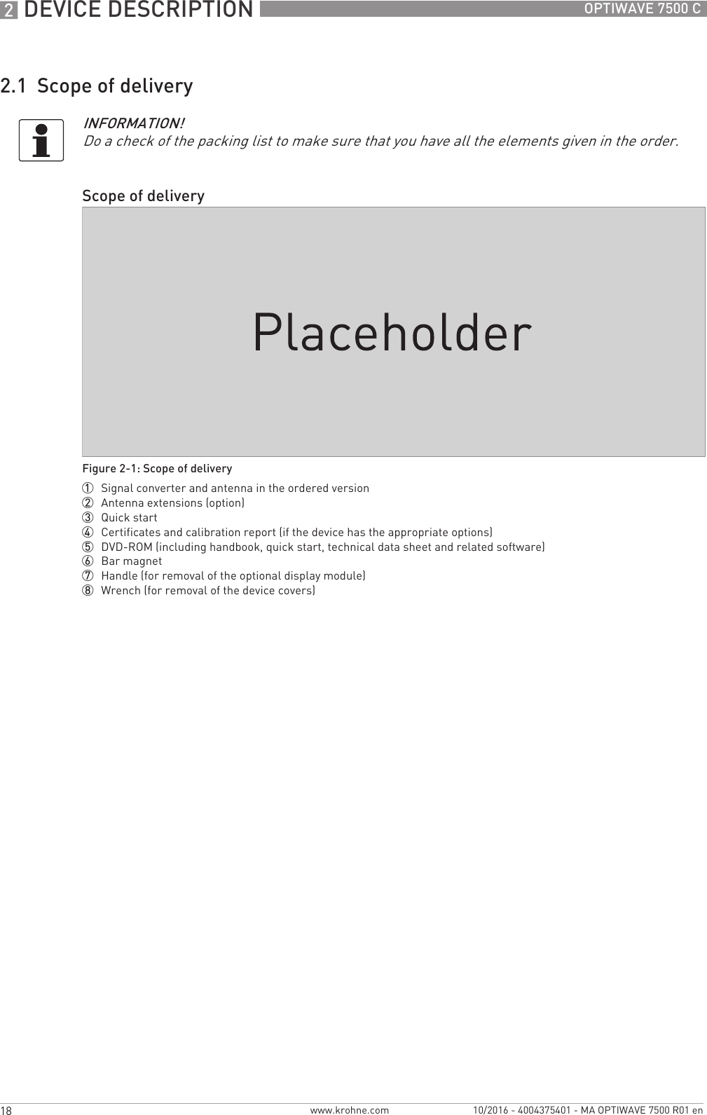
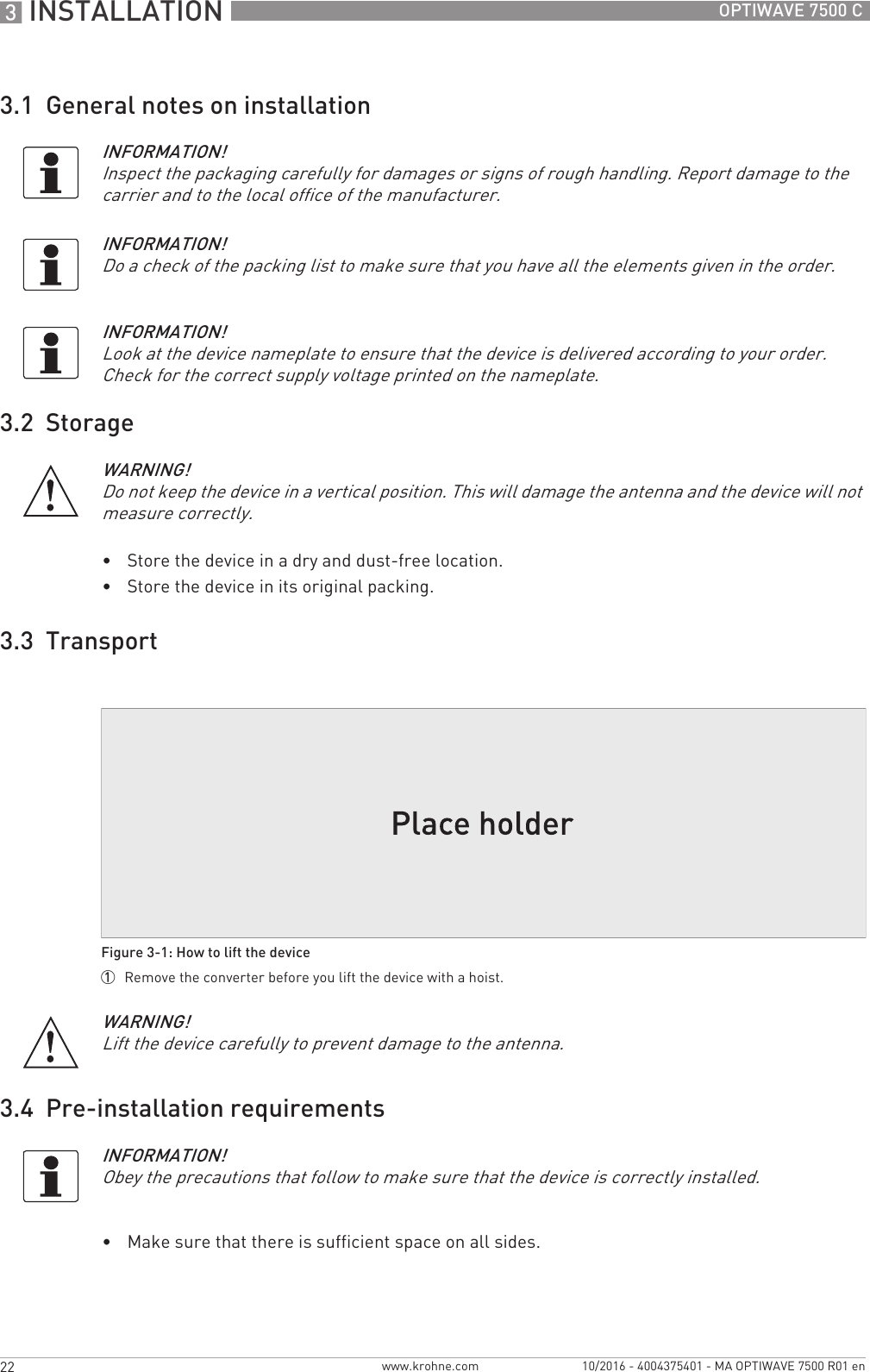
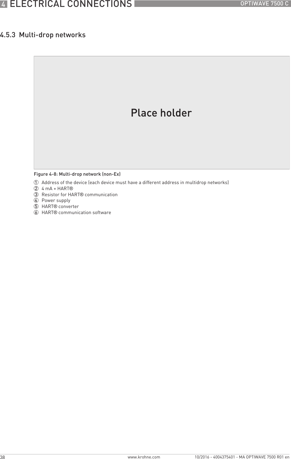
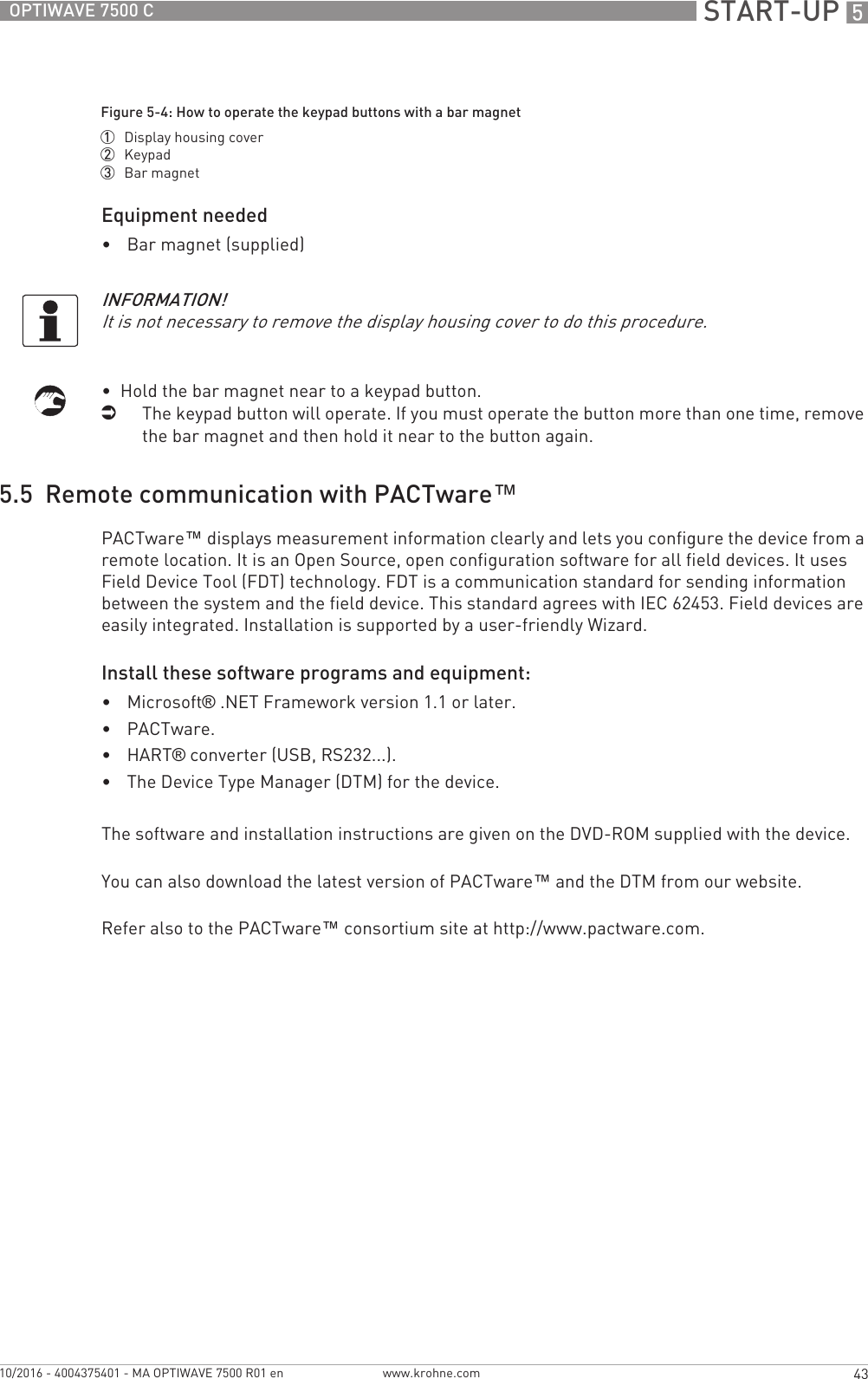
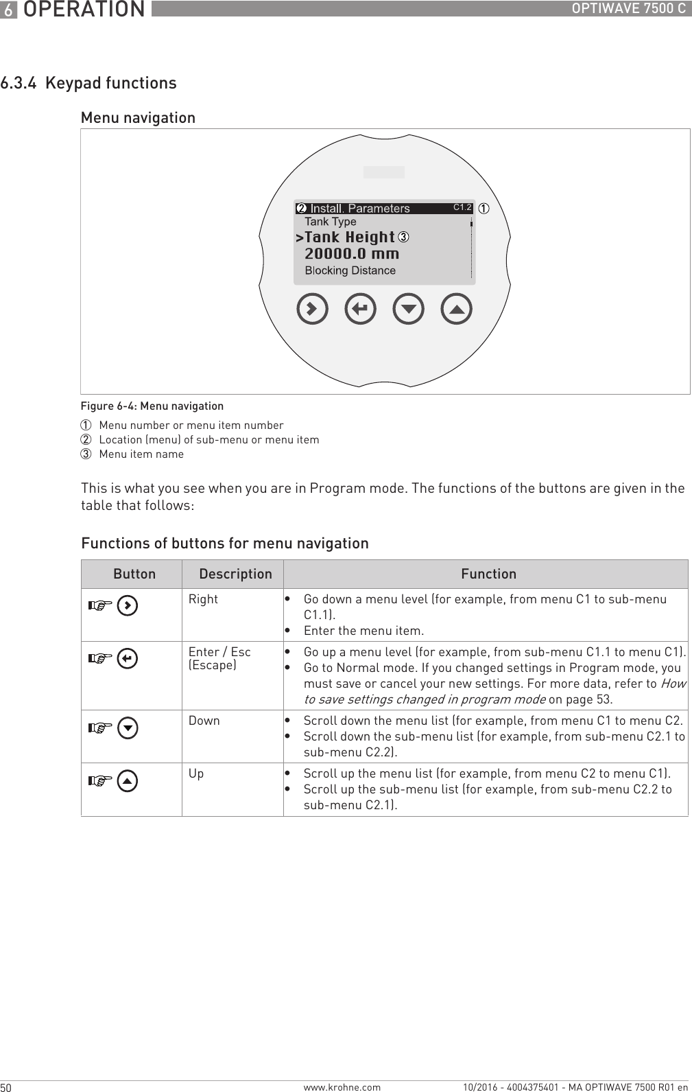
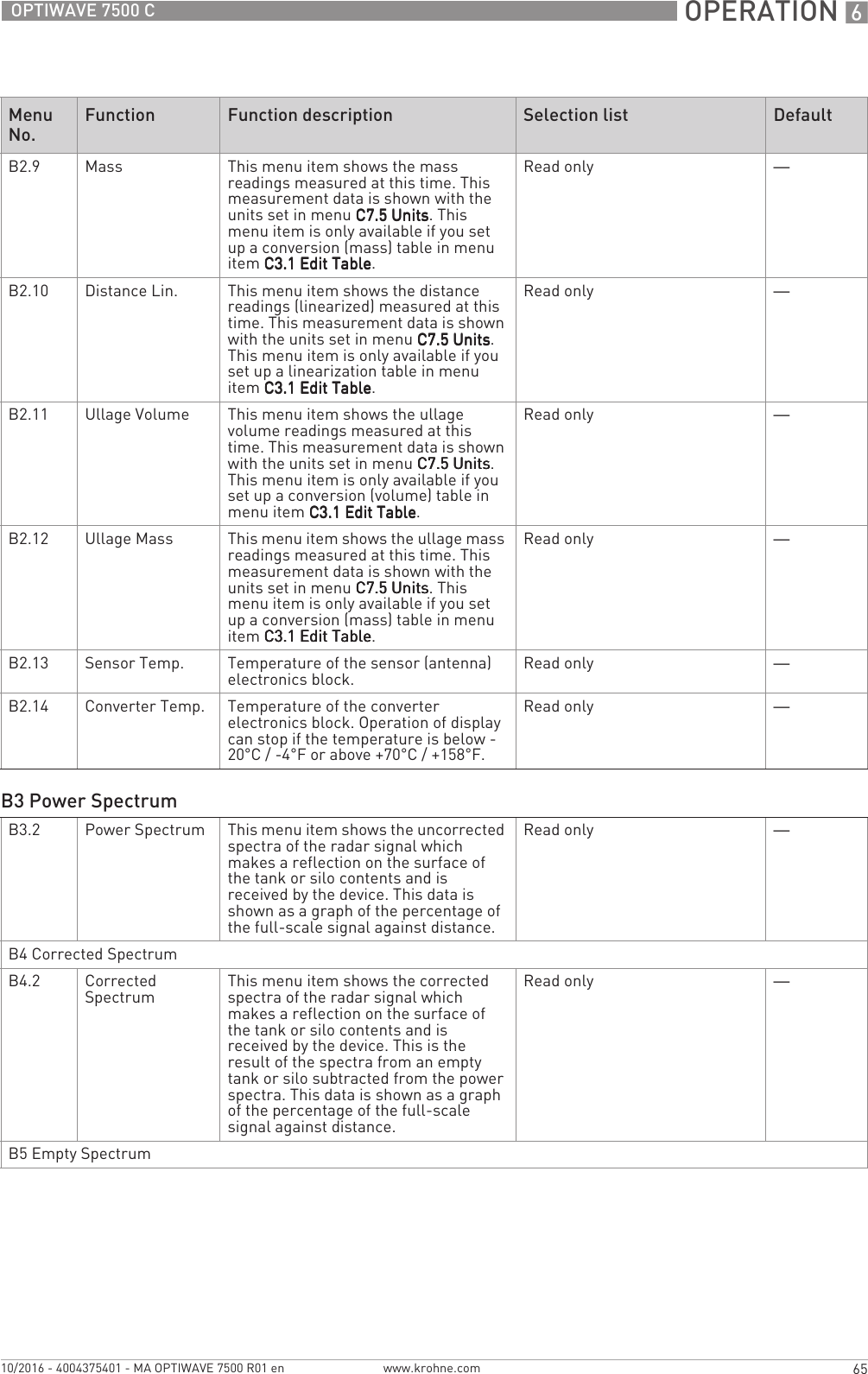
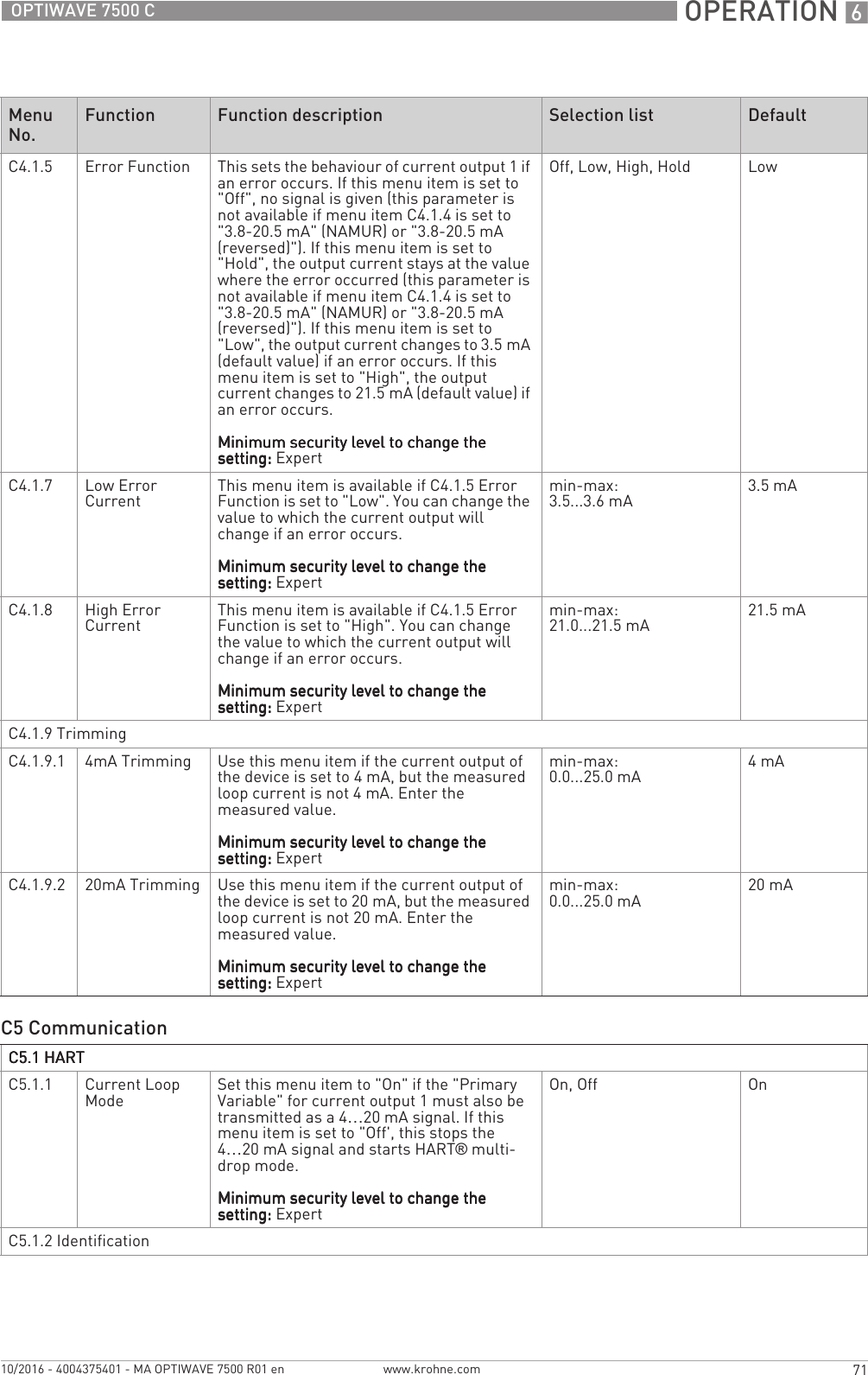
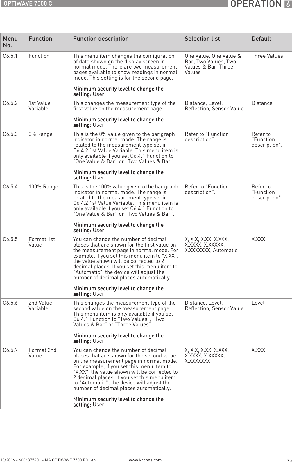
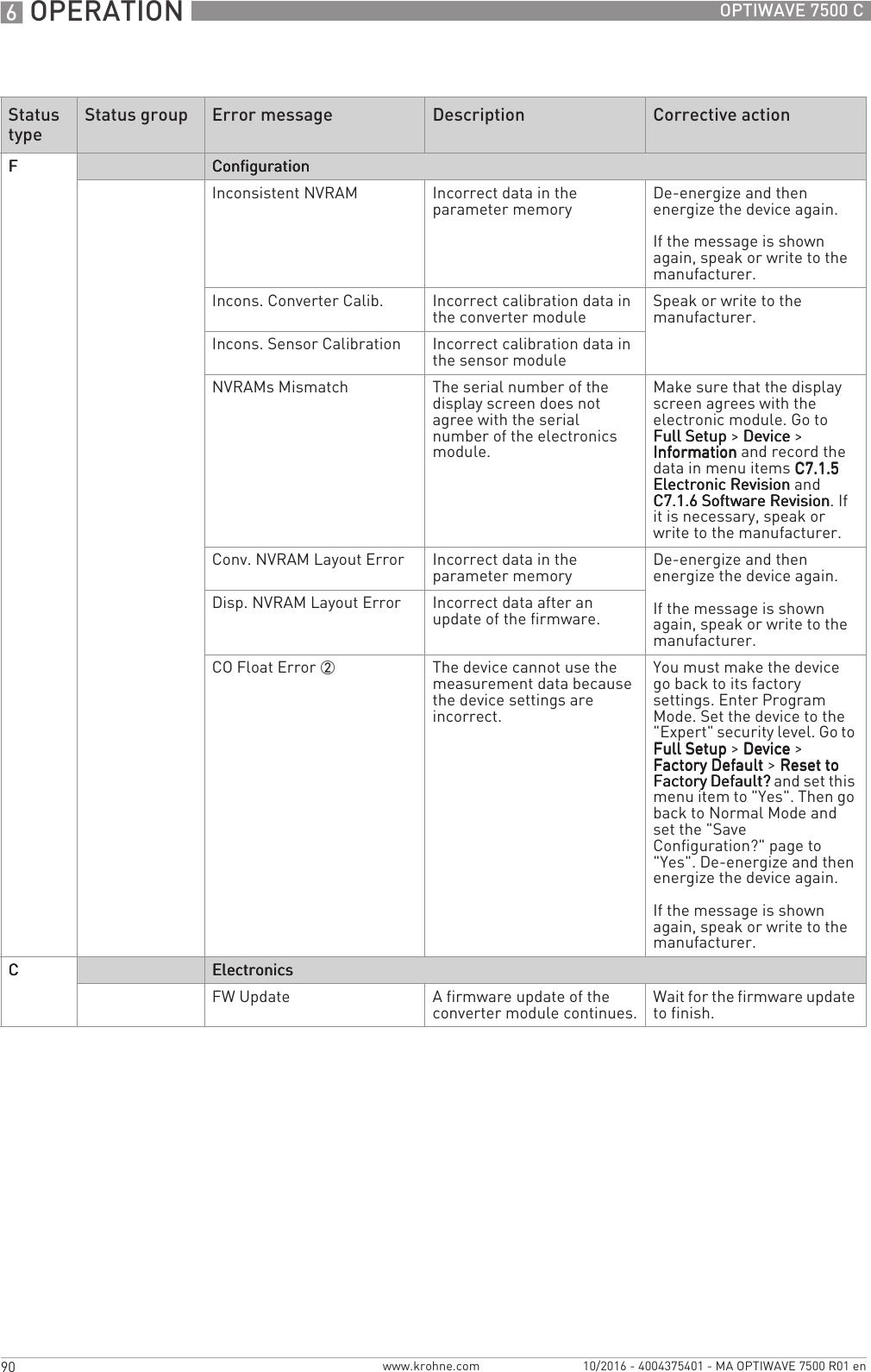
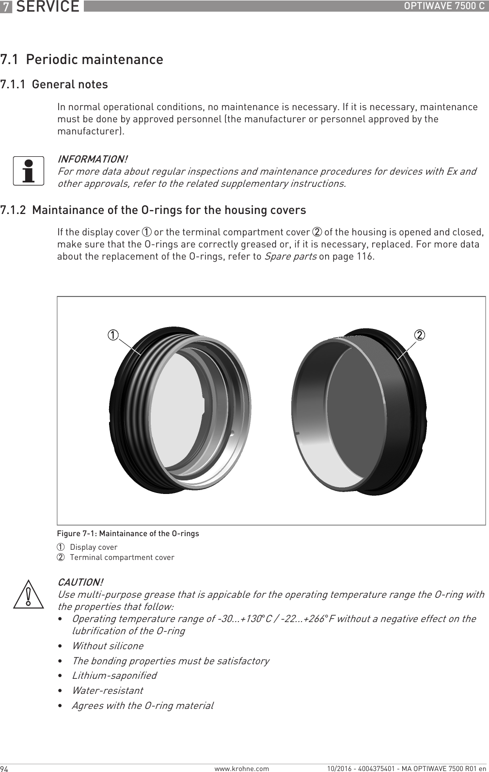
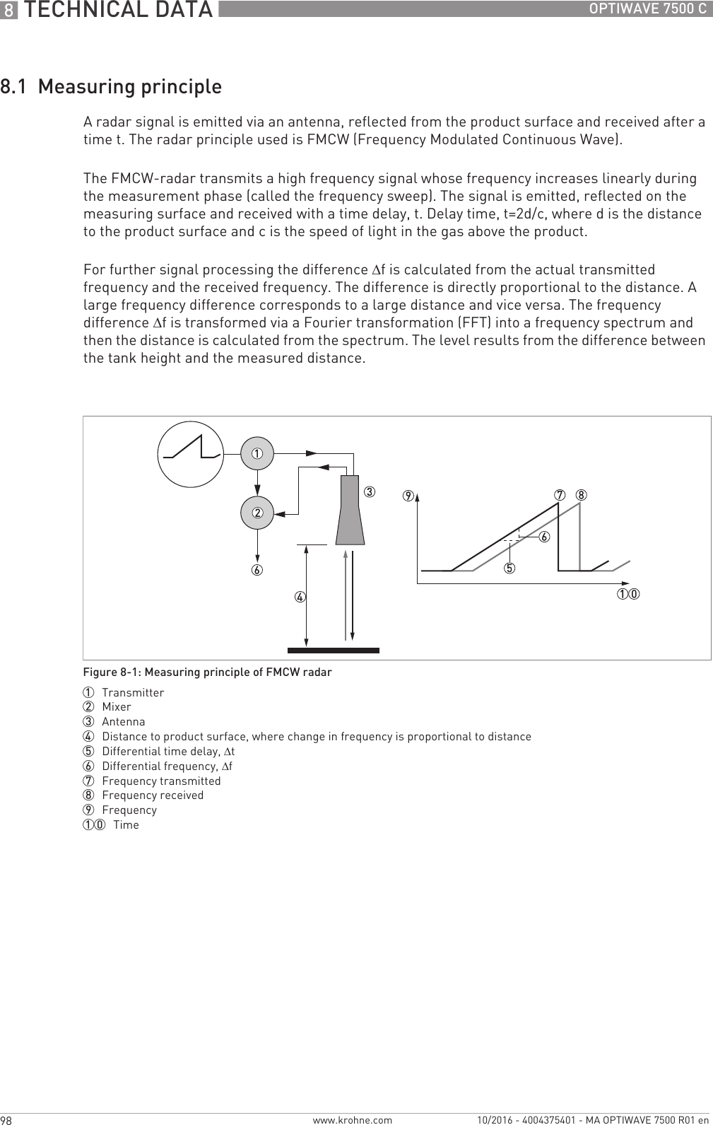
![6 OPERATION 48 OPTIWAVE 7500 Cwww.krohne.com 10/2016 - 4004375401 - MA OPTIWAVE 7500 R01 enIf your security level is too low, the display will show a "lock" symbol adjacent to menu items in Program mode. If it is necessary to change this setting, go to menu item menu item A3 Login or C7.2.1 Login and set the device to the correct security level.How to change the password• Push [>>>>] to enter Program Mode.• Push 2 × [], [>>>>], 5 × [], [>>>>], [] and [>>>>] to go to the menu item C7.2.1 Login.• Push [>>>>] to enter the menu item.• Enter the password used at this time for a given security level ("Operator" or "Expert"). If it is the default password, refer to the table at the start of this section.• Push [^^^^] and [] to go to the menu item C7.2.2 Change Password.• Push [>>>>] to enter the menu item.• Enter the password used at this time for the security level set at the start of this procedure. If it is the default password, refer to the table at the start of this section.• Enter the new password.iIf you change the password for the "Operator" security level, then the first three digits must be zero (000x). The last digit can be a number (1...9) or a letter (A...F). If you change the password for the "Expert" security level, then the first two digits must be zero (00xx). The last two digits can be a number (1...9) or a letter (A...F).• Enter the new password again.• Push 6 × [^^^^] to go back to normal mode.Operator 0009•Read: Measurement data and error messages available at the "User" security level (normal mode and menu items B2 Actual Values and C7.3.1 Message View)•Change: Binary Output (C4.3)•Change: All HART® settings (C5) – but not C5.1.1 Current Loop ModeNOTE:NOTE:NOTE:NOTE: You can change the password for the "Operator" security level in menu item C7.2.2 Change Password. Refer to the INFORMATION! note that follows.User —•Read: Measurement data and error messages (normal mode and men items B2 Actual Values and C7.3.1 Message View)•Read: All settings in menus A Quick Setup, B Test and C Full Setup•Change: All settings in menu C6 Display (language, backlight on/off, screen contrast and measurement data display options (normal mode, pages 1 and 2)) and C7.5 Units (length, volume, mass and custom units)•Change: Security level. Go to menu item A3 Login or C7.2.1 Login to change from "User" to "Operator" or "Expert" security levelsFigure 6-3: Lock symbol1 Lock symbol. If the display shows this symbol, you cannot change the setting.](https://usermanual.wiki/KROHNE/FMCW80G74TA/User-Guide-3267690-Page-48.png)
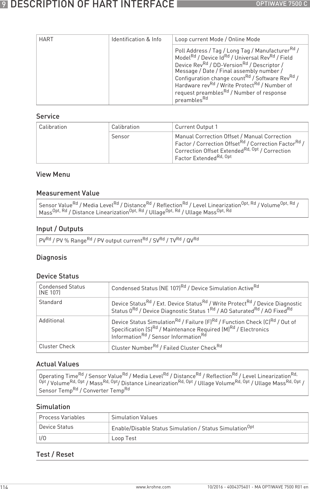
![OPERATION 649OPTIWAVE 7500 Cwww.krohne.com10/2016 - 4004375401 - MA OPTIWAVE 7500 R01 eniEnd of the procedure.6.3.3 How to get access to the Quick Setup menuThe Quick Setup menu contains the menu items that are necessary for most configurations of the device. The menu items are divided into 2 groups: "Standard Setup" and "Empty Spectrum". The "Standard Setup" group lets the user (with security level "expert") set the tank height, tank type (process, storage etc.), output variable, output current range, 0% range, 100% range, error function and error delay. "Empty Spectrum" is a procedure that finds interference signals in the tank and uses a filter to remove them from the measurement data.Do the steps that follow:• Push [>>>>] to enter Program Mode.• Push [>>>>], 2 × [] to go to the menu item A3 Login.• Enter the password used at this time for the "Expert" security level. If it is the default password, refer to Protection of the device settings (security levels) on page 47.• Push [^^^^], [] and [>>>>] to go to the menu item A4.1 Standard Setup.• Push [>>>>]. Do the basic configuration of the device in the "Standard Setup" menu. For more data on the procedure, refer to Standard Setup on page 79. Push [^^^^] at the end of each step of the procedure to continue to the next step.• Push [] and [>>>>] to go to the menu item A4.2.1 Record Spectrum.• Push [>>>>] to start the empty spectrum recording procedure. For more data,. Push [^^^^] at the end of each step of the procedure to continue to the next step.INFORMATION!Each security level has a four-digit hexadecimal password.The first three digits of the password for the "Operator" security level must be zero (000x). The last digit can be a number (1...9) or a letter (A...F).The first two digits of the password for the "Expert" security level must be zero (00xx). The last two digits can be a number (1...9) or a letter (A...F).INFORMATION!Make a note of the password and keep it in a safe place. If you lose the password, please speak or write to your supplier.INFORMATION!If you de-energize and then energize the device, the security level will go back to "User".CAUTION!If you did not supply all installation data to the supplier before the delivery, the standard setup procedure in the Quick Setup menu is mandatory.](https://usermanual.wiki/KROHNE/FMCW80G74TA/User-Guide-3267690-Page-49.png)
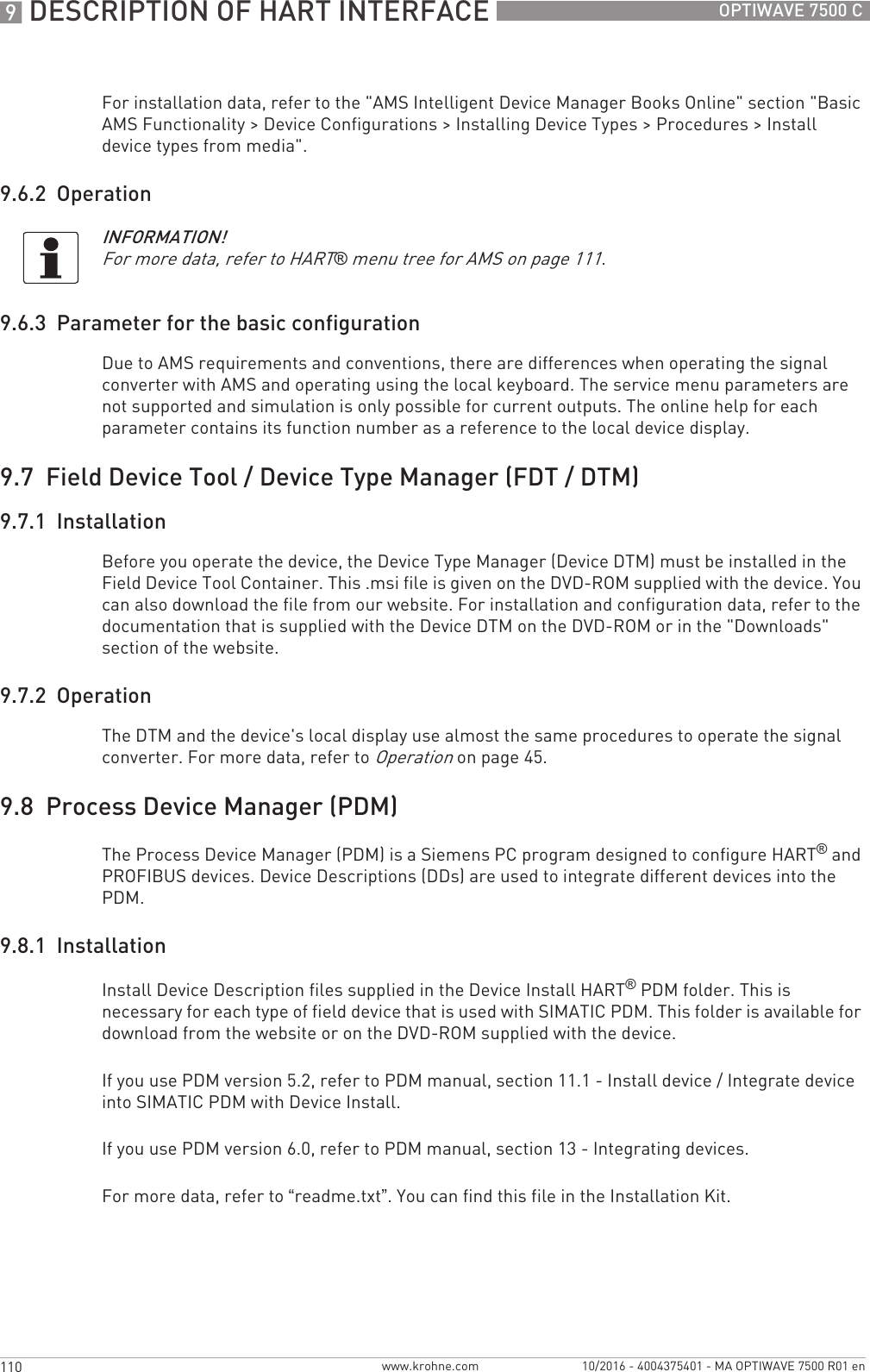
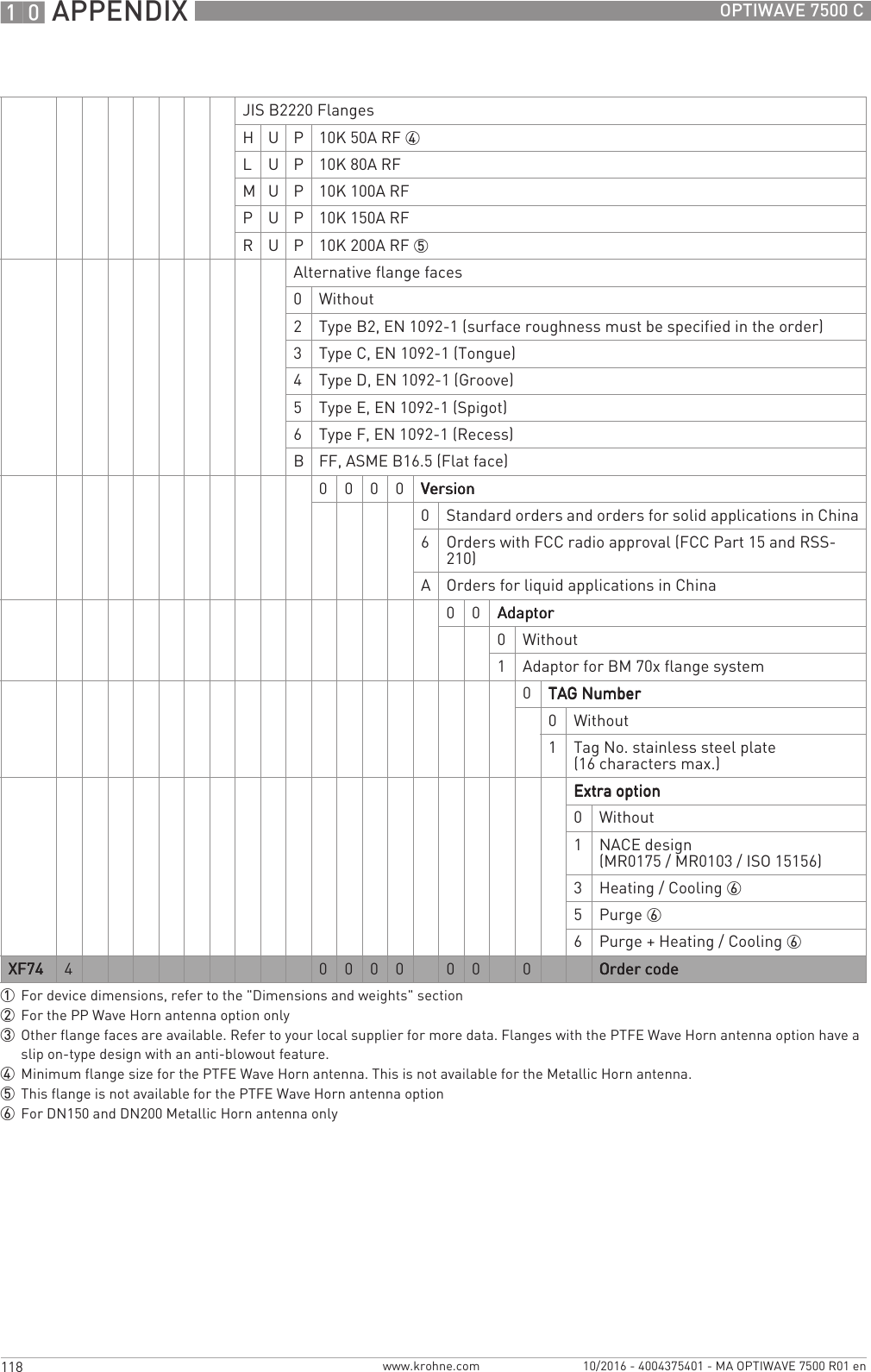
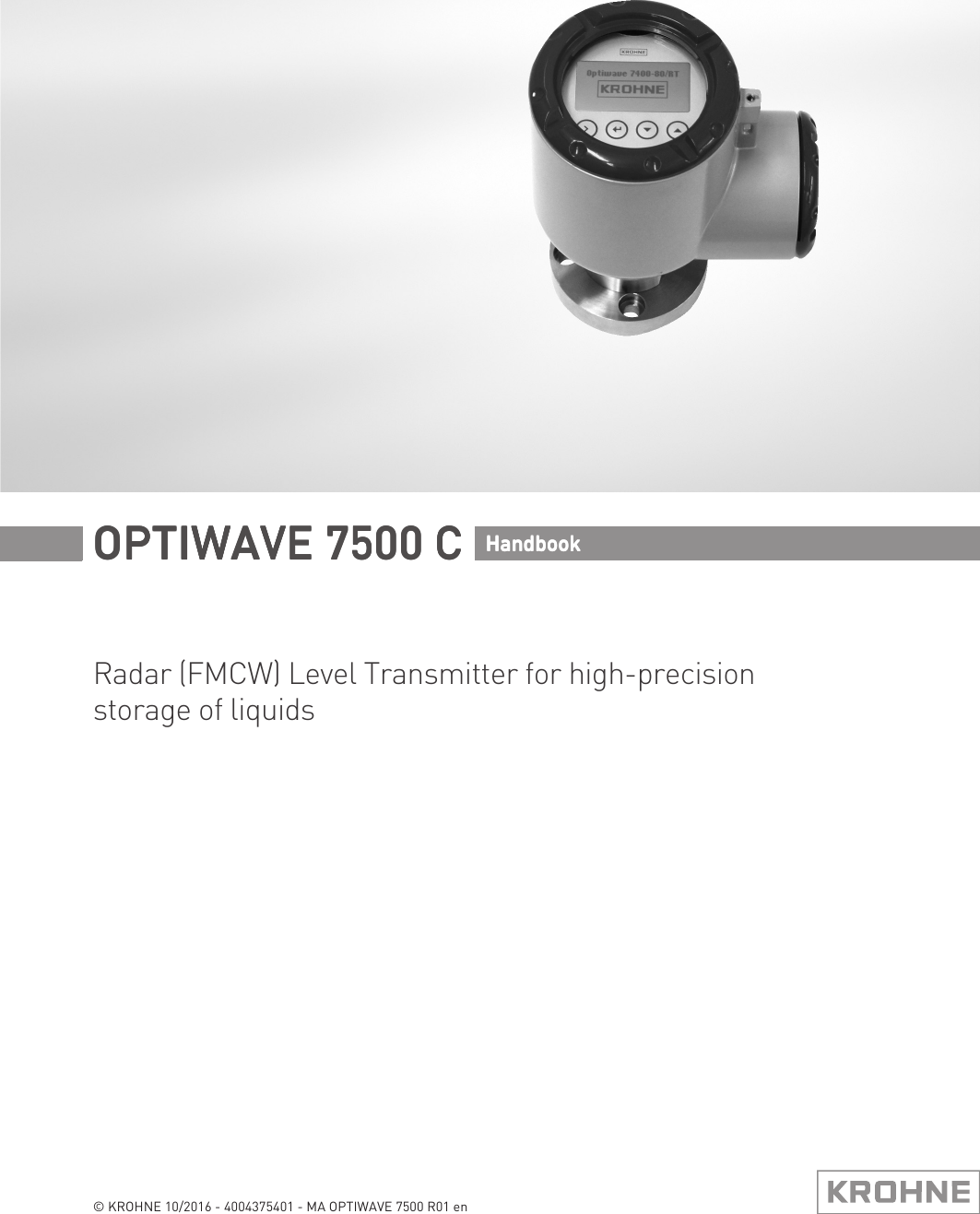
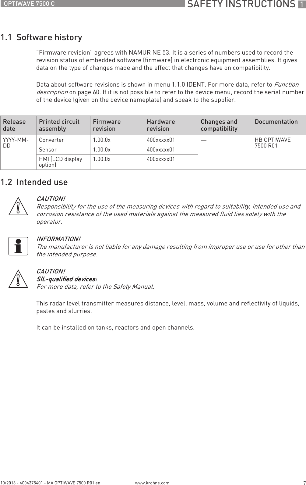
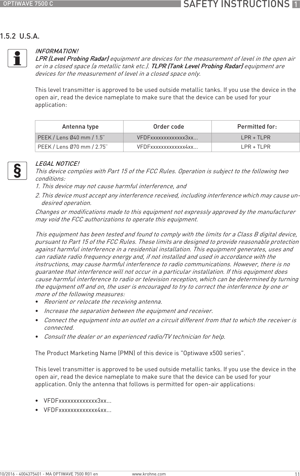
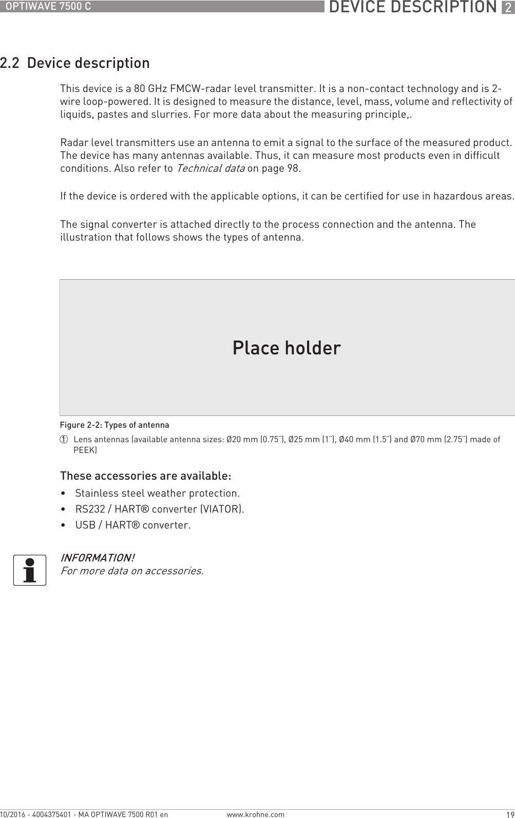
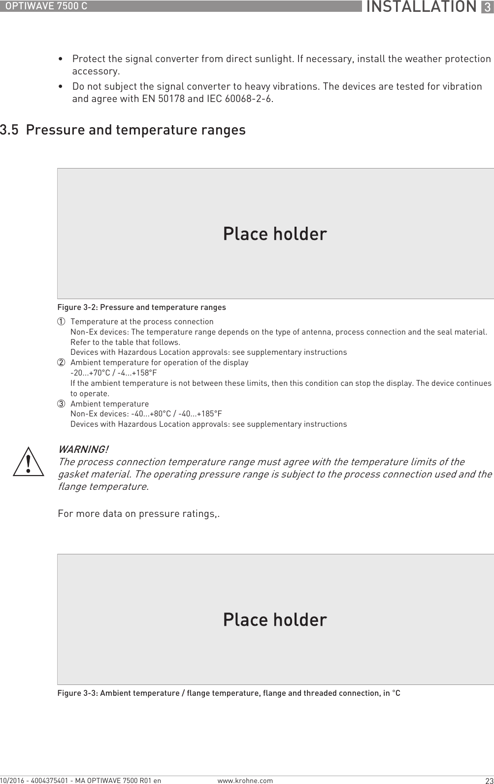
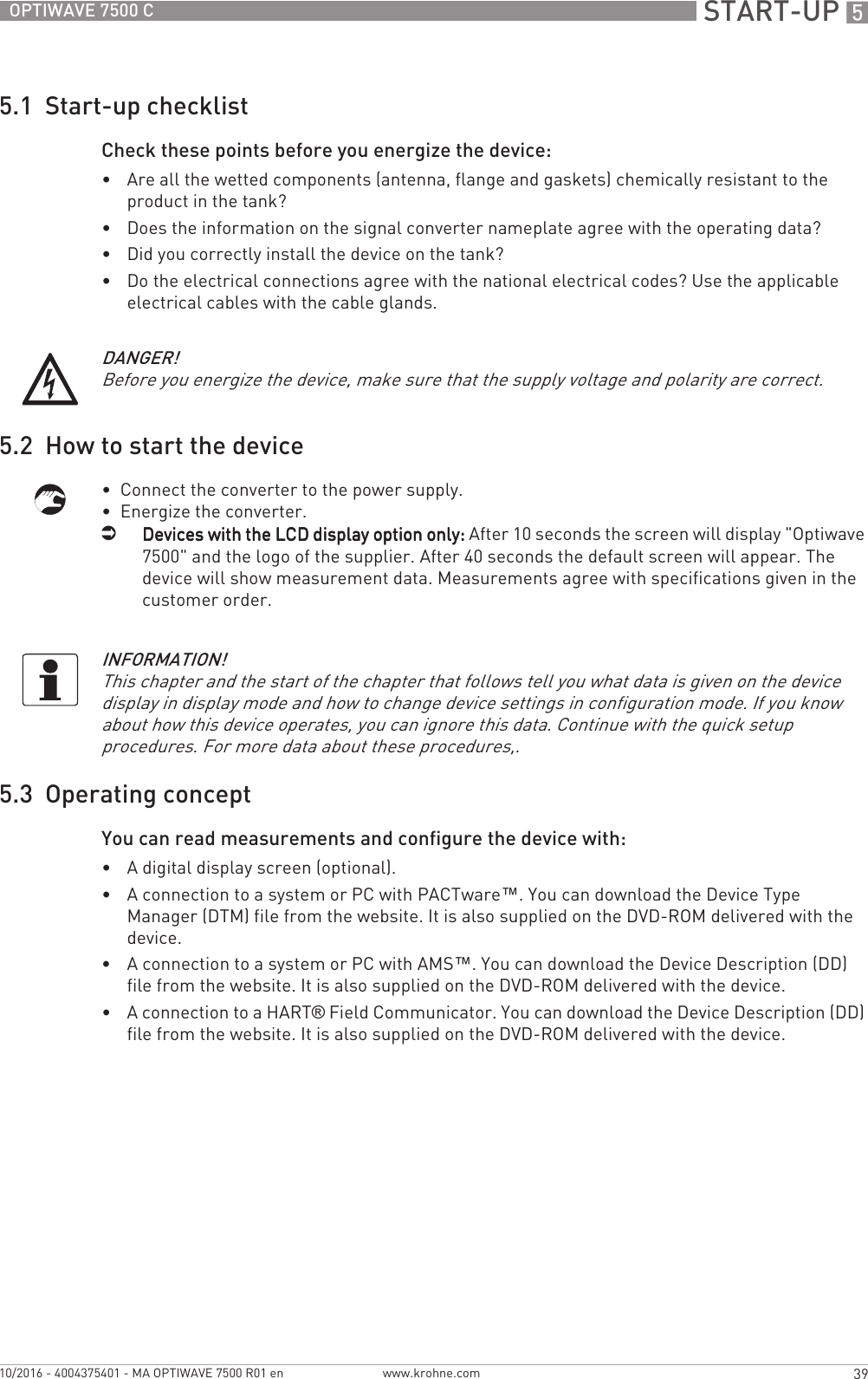
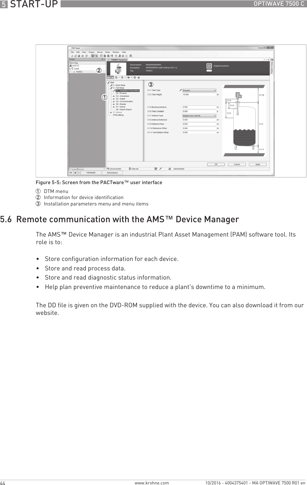
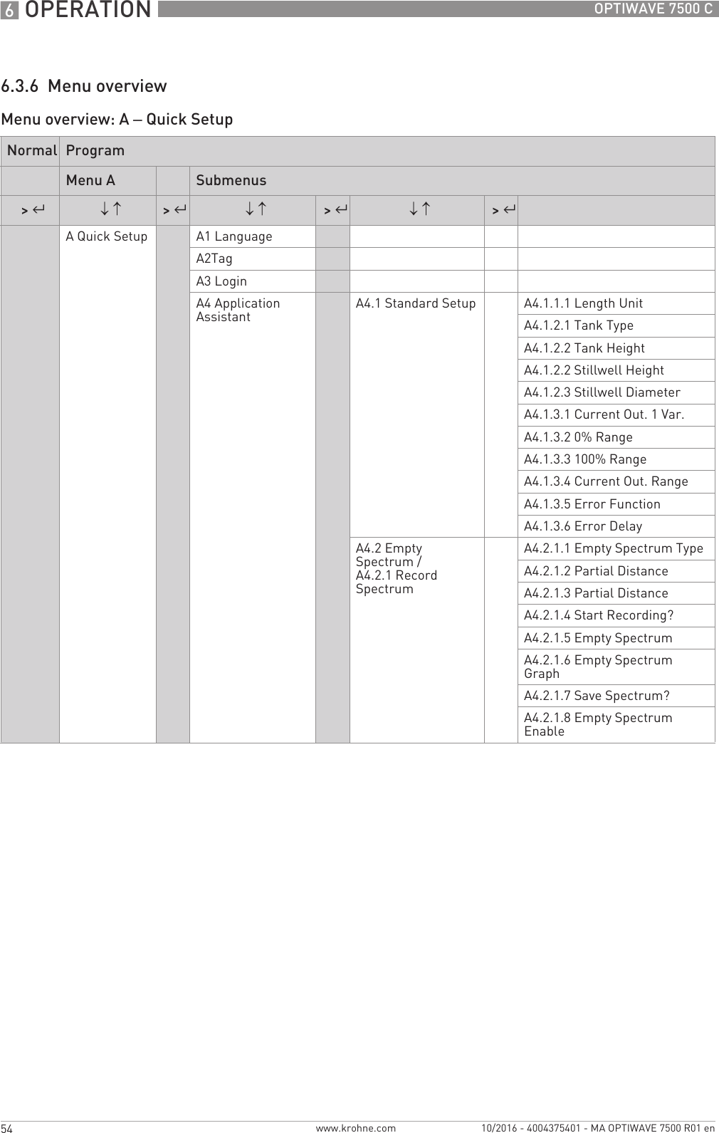
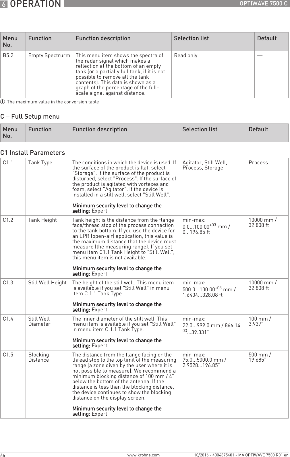
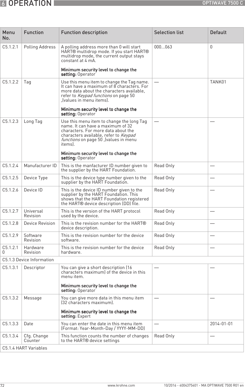
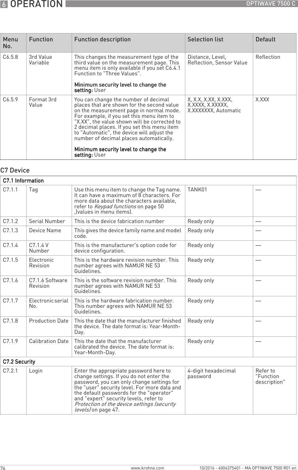
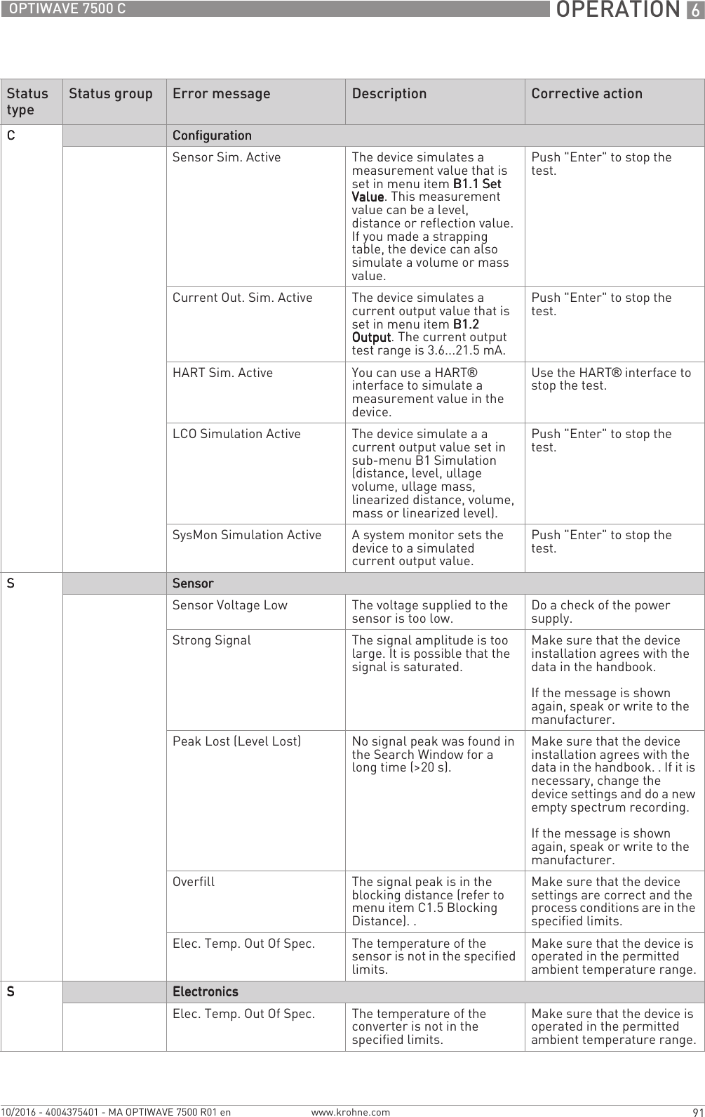
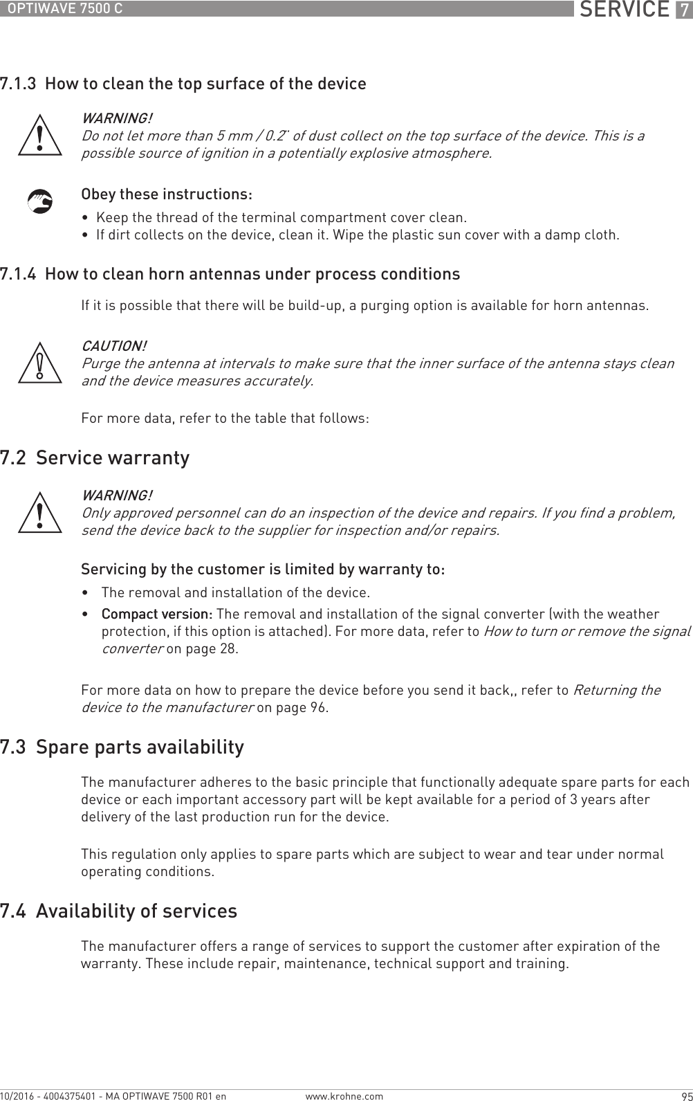
![OPERATION 651OPTIWAVE 7500 Cwww.krohne.com10/2016 - 4004375401 - MA OPTIWAVE 7500 R01 enThis is what you see when you select a menu item that has a list of parameters. The functions of the buttons are given in the table that follows:Function of buttons in menu items that have a list of parametersLists of parameters in menu itemsFigure 6-5: Lists of parameters in menu items1 Menu item with parameter stored at this time (first screen). Push [>>>>] to enter the menu item.2 Push [] or [] to change the parameter3 Push [^^^^] to set the new parameter and go back to the menu level4 Parameter5 Menu item name6 A "tick" symbol shows that there is a new setting (the new setting is not saved at this time)Button Description FunctionRight —Enter / Esc (Escape) Select the parameter and go back to the menuDown Move down the listUp Move up the list](https://usermanual.wiki/KROHNE/FMCW80G74TA/User-Guide-3267690-Page-51.png)
![6 OPERATION 52 OPTIWAVE 7500 Cwww.krohne.com 10/2016 - 4004375401 - MA OPTIWAVE 7500 R01 enThis is what you see when you select a menu item that has a value.The functions of the buttons are given in the table that follows:Function of buttons in menu items that have valuesValues in menu itemsFigure 6-6: Values in menu items1 Menu item with values stored at this time (first screen). Push [>>>>] to enter the menu item. A cursor shows on the first digit.2 Push [>>>>] again and again to move the cursor. Push [] or [] to change the value of the digit. If the digit is part of a number, then make a selection from 0...9. If the digit is part of a custom unit name, then refer to the tables at the end of this section for a list of the available characters. If the cursor is on the decimal point, you can change the position of the decimal point.3 Push [^^^^] to set the new parameter and go back to the menu level4 Make a selection: put the cursor on a digit or the decimal point.5 Menu item name6 The factory default value (left side) and factory default symbol (right side)7 The minimun and maximum values (min./max.) for this menu item (left side) and min./max. symbol (right side)8 A "tick" symbol shows that there is a new setting (the new setting is not saved at this time)INFORMATION!If menu items have values that you can change, very large and very small values can be written as a value with an exponent (bn). For example, if the value shown on the display is 100.00+03, this value is equal to 100 × 103or 100000.Button Description FunctionRight•Enter the menu item and see the value stored at this time.•Enter the menu item configuration level to change the value.•Move the cursor to the next digit on the right. If the cursor is on the last digit, push [>>>>] again to go back to the first digit. You can also put the cursor on the decimal point.Enter / Esc (Escape) Accept the value and go back to the sub-menu.Down If the cursor is on a number, this button decreases the digit value. If the cursor is on the decimal point, this button moves the decimal point to the left (this decreases the value by a factor of 10).Up If the cursor is on a number, this button increases the digit value. If the cursor is on the decimal point, this button moves the decimal point to the right (this increases the value by a factor of 10).](https://usermanual.wiki/KROHNE/FMCW80G74TA/User-Guide-3267690-Page-52.png)
![OPERATION 653OPTIWAVE 7500 Cwww.krohne.com10/2016 - 4004375401 - MA OPTIWAVE 7500 R01 enNumbersLower case lettersUpper case lettersSpecial characters6.3.5 How to save settings changed in program mode• When you have changed parameters in all the necessary menu items, push [^^^^] to accept the new parameter.• Push [^^^^] again and again to go back to the "Save Configuration?" screen.• The device will ask you to save or cancel your settings. Push [] or [] to make a selection from YesYesYesYes, NoNoNoNo or BackBackBackBack. BackBackBackBack makes the display go back to Program mode. If this screen is set to "Yes" or No", push [^^^^] to accept (Yes) or reject (No) the new settings.iIf you push [^^^^] when the screen is set to "Yes" or No", the display goes back to normal mode.INFORMATION!Values in menu itemsValues in menu itemsValues in menu itemsValues in menu itemsIf the digit is part of a custom unit name, then refer to the list of available characters that follows:0123456789a b c d e f g h i jk l m n o p q r s tu v w x y zA B C D E F G H I JK L M N O P Q R S TU V W X Y Z2 3_ - / ....](https://usermanual.wiki/KROHNE/FMCW80G74TA/User-Guide-3267690-Page-53.png)
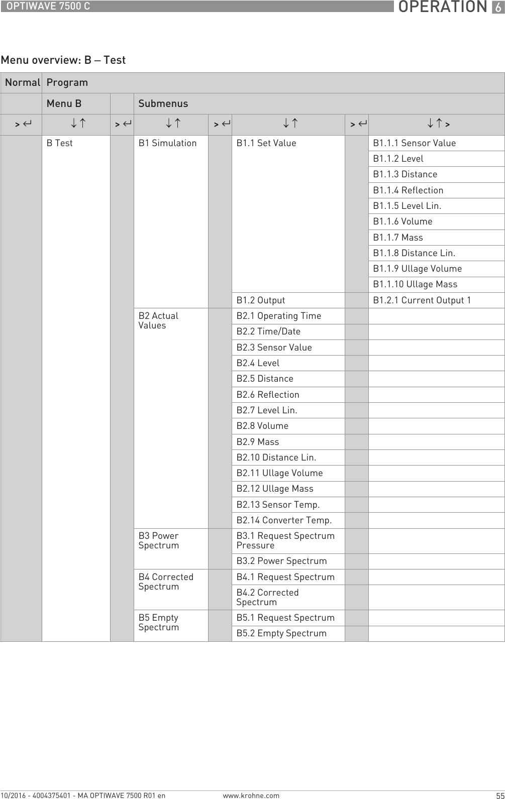
![OPERATION 661OPTIWAVE 7500 Cwww.krohne.com10/2016 - 4004375401 - MA OPTIWAVE 7500 R01 enB – Test menuA4.1 Standard Setup This starts a quick set-up procedure applicable to most applications. You can set the length unit, installation specifications (tank type, tank height, still well height, still well diameter etc.) and current output specifications (0% range, 1000% range, error function etc.). For more data about the functions, refer to Table C – Full Setup, in this section. For more data about the procedure, refer to Standard Setup on page 79.Minimum security level to do the Minimum security level to do the Minimum security level to do the Minimum security level to do the procedure:procedure:procedure:procedure: ExpertA4.2 Fixed and moving objects in the tank cause interference signals. Put them through this filter to correctly measure the tank contents. This menu item starts a quick set-up procedure. We recommend that the tank is empty or only filled to the minimum level before you do the procedure. We also recommend that if you installed the device on a tank that has equipment with parts that move (e.g. agitators), start the equipment. Set the Save Save Save Save Spectrum? Spectrum? Spectrum? Spectrum? step to "Yes", Empty Empty Empty Empty Spectrum EnableSpectrum EnableSpectrum EnableSpectrum Enable step to "Enable" at the end the procedure and set the Save Configuration? screen to "Yes" to use the data. For more data about the procedure, refer to Empty spectrum recording on page 82. Refer also to "How to make a filter to remove radar signal interference" on page 87.Minimum security level to do the Minimum security level to do the Minimum security level to do the Minimum security level to do the procedure:procedure:procedure:procedure: ExpertMenu No.Function Function description Selection list DefaultB1 SimulationB1.1 Set ValueB1.1 Set ValueB1.1 Set ValueB1.1 Set ValueB1.1.2 Level This sets the device to a given test level value. This procedure sends an output signal that agrees with the test reading. Output will change to the selected value, independent of the measurement data.When you push [^^^^] to confirm the value, the display shows the question "Start Simulation?" Push [] or [] to set the display to "Yes". Push [^^^^]again to start the test.Minimum security level to do the Minimum security level to do the Minimum security level to do the Minimum security level to do the procedure:procedure:procedure:procedure: Usermin-max:-4900.0...+5100.0 m / -1076...+16732 ft+0 mMenu No.Function Function description Selection list Default](https://usermanual.wiki/KROHNE/FMCW80G74TA/User-Guide-3267690-Page-61.png)
![6 OPERATION 62 OPTIWAVE 7500 Cwww.krohne.com 10/2016 - 4004375401 - MA OPTIWAVE 7500 R01 enB1.1.3 Distance This sets the device to a given test distance value. This procedure sends an output signal that agrees with the test reading. Output will change to the selected value, independent of the measurement data.When you push [^^^^] to confirm the value, the display shows the question "Start Simulation?" Push [] or [] to set the display to "Yes". Push [^^^^]again to start the test.Minimum security level to do the Minimum security level to do the Minimum security level to do the Minimum security level to do the procedure:procedure:procedure:procedure: Usermin-max:-4900.0...+5100.0 m / -1076...+16732 ft+20.0 mB1.1.4 Reflection This sets the device to a given test reflection value. This procedure sends an output signal that agrees with the test reading. Output will change to the selected value, independent of the measurement data.When you push [^^^^] to confirm the value, the display shows the question "Start Simulation?" Push [] or [] to set the display to "Yes". Push [^^^^]again to start the test.Minimum security level to do the Minimum security level to do the Minimum security level to do the Minimum security level to do the procedure:procedure:procedure:procedure: Usermin-max:0...100% 0%B1.1.5 Level Lin. This sets the device to a given test level value (linearized). This menu item is only available if you set up a linearization table in menu item C3.1 C3.1 C3.1 C3.1 Edit TableEdit TableEdit TableEdit Table. This procedure sends an output signal that agrees with the test reading. Output will change to the selected value, independent of the measurement data.When you push [^^^^] to confirm the value, the display shows the question "Start Simulation?" Push [] or [] to set the display to "Yes". Push [^^^^]again to start the test.Minimum security level to do the Minimum security level to do the Minimum security level to do the Minimum security level to do the procedure:procedure:procedure:procedure: Usermin-max:-4900.0...+5100.0 m / -1076...+16732 ft+0 mB1.1.6 Volume This sets the device to a given test volume value. This menu item is only available if you set up a conversion (volume) table in menu item C3.1 Edit C3.1 Edit C3.1 Edit C3.1 Edit TableTableTableTable. This procedure sends an output signal that agrees with the test reading. Output will change to the selected value, independent of the measurement data.When you push [^^^^] to confirm the value, the display shows the question "Start Simulation?" Push [] or [] to set the display to "Yes". Push [^^^^]again to start the test.Minimum security level to do the Minimum security level to do the Minimum security level to do the Minimum security level to do the procedure:procedure:procedure:procedure: Usermin-max:0...1.00+06m³+0 m³Menu No.Function Function description Selection list Default](https://usermanual.wiki/KROHNE/FMCW80G74TA/User-Guide-3267690-Page-62.png)
![OPERATION 663OPTIWAVE 7500 Cwww.krohne.com10/2016 - 4004375401 - MA OPTIWAVE 7500 R01 enB1.1.7 Mass This sets the device to a given test mass value. This menu item is only available if you set up a conversion (mass) table in menu item C3.1 Edit C3.1 Edit C3.1 Edit C3.1 Edit TableTableTableTable. This procedure sends an output signal that agrees with the test reading. Output will change to the selected value, independent of the measurement data.When you push [^^^^] to confirm the value, the display shows the question "Start Simulation?" Push [] or [] to set the display to "Yes". Push [^^^^]again to start the test.Minimum security level to do the Minimum security level to do the Minimum security level to do the Minimum security level to do the procedure:procedure:procedure:procedure: Usermin-max:0...10.000+09kg0kgB1.1.8 Distance Lin. This sets the device to a given test distance value (linearized). This menu item is only available if you set up a linearization table in menu item C3.1 C3.1 C3.1 C3.1 Edit TableEdit TableEdit TableEdit Table. This procedure sends an output signal that agrees with the test reading. Output will change to the selected value, independent of the measurement data.When you push [^^^^] to confirm the value, the display shows the question "Start Simulation?" Push [] or [] to set the display to "Yes". Push [^^^^]again to start the test.Minimum security level to do the Minimum security level to do the Minimum security level to do the Minimum security level to do the procedure:procedure:procedure:procedure: Usermin-max:-4900.0...+5100.0 m +0 mB1.1.9 Ullage Volume This sets the device to a given test ullage volume value. This menu item is only available if you set up a conversion (volume) table in menu item C3.1 Edit C3.1 Edit C3.1 Edit C3.1 Edit TableTableTableTable. This procedure sends an output signal that agrees with the test reading. Output will change to the selected value, independent of the measurement data.When you push [^^^^], the display shows the question "Start Simulation?" Push [] or [] to set the display to "Yes". Push [^^^^]again to start the test.Minimum security level to do the Minimum security level to do the Minimum security level to do the Minimum security level to do the procedure:procedure:procedure:procedure: Usermin-max:0...1.00+06m³1Menu No.Function Function description Selection list Default](https://usermanual.wiki/KROHNE/FMCW80G74TA/User-Guide-3267690-Page-63.png)
![6 OPERATION 64 OPTIWAVE 7500 Cwww.krohne.com 10/2016 - 4004375401 - MA OPTIWAVE 7500 R01 enB1.1.10 Ullage Mass This sets the device to a given test ullage mass value. This menu item is only available if you set up a conversion (mass) table in menu item C3.1 Edit C3.1 Edit C3.1 Edit C3.1 Edit TableTableTableTable. This procedure sends an output signal that agrees with the test reading. Output will change to the selected value, independent of the measurement data.When you push [^^^^] to confirm the value, the display shows the question "Start Simulation?" Push [] or [] to set the display to "Yes". Push [^^^^]again to start the test.Minimum security level to do the Minimum security level to do the Minimum security level to do the Minimum security level to do the procedure:procedure:procedure:procedure: Usermin-max:0...10.000+09kg1B1.2 OutputB1.2 OutputB1.2 OutputB1.2 OutputB1.2.1 Current Output 1 This sets analogue output 1 to a test value [mA]. Output will change to the selected value, independent of the measured value.When you push [^^^^] to confirm the value, the display shows the question "Start Simulation?" Push [] or [] to set the display to "Yes". Push [^^^^]again to start the test.Minimum security level to do the Minimum security level to do the Minimum security level to do the Minimum security level to do the procedure:procedure:procedure:procedure: User3.6...21.5 mA 21.5 mAB2 Actual ValuesB2.1 Operating Time [s] This is the total time that the device is energized in seconds. Read only —B2.4 Level This menu item shows the level readings measured at this time. This measurement data is shown with the units set in menu C7.5 UnitsC7.5 UnitsC7.5 UnitsC7.5 Units.Read only —B2.5 Distance This menu item shows the distance readings measured at this time. This measurement data is shown with the units set in menu C7.5 UnitsC7.5 UnitsC7.5 UnitsC7.5 Units.Read only —B2.6 Reflection This menu item shows the percentage of the emitted radar signal which makes a reflection on the surface of the tank or silo contents and is received by the device.Read only —B2.7 Level Lin. This menu item shows the level readings (linearized) measured at this time. This measurement data is shown with the units set in menu C7.5 UnitsC7.5 UnitsC7.5 UnitsC7.5 Units. This menu item is only available if you set up a linearization table in menu item C3.1 Edit TableC3.1 Edit TableC3.1 Edit TableC3.1 Edit Table.Read only —B2.8 Volume This menu item shows the volume readings measured at this time. This measurement data is shown with the units set in menu C7.5 UnitsC7.5 UnitsC7.5 UnitsC7.5 Units. This menu item is only available if you set up a conversion (volume) table in menu item C3.1 Edit TableC3.1 Edit TableC3.1 Edit TableC3.1 Edit Table.Read only —Menu No.Function Function description Selection list Default](https://usermanual.wiki/KROHNE/FMCW80G74TA/User-Guide-3267690-Page-64.png)
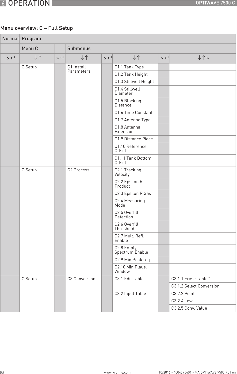
![OPERATION 669OPTIWAVE 7500 Cwww.krohne.com10/2016 - 4004375401 - MA OPTIWAVE 7500 R01 enC2.7 Mult. Refl. Enable Multiple reflections will cause the device to display smaller level readings. Installation of the device on a manhole or at the centre of a dome roof, and high dielectric products (εr > 5) can cause multiple reflections. A very calm surface or a tank with a small convex or flat roof can also cause multiple reflections.If this function is in operation, the device looks for the first signal peak below the process connection. This signal peak is then used to measure the level of the tank contents. If this function is not in operation, the device looks for the largest signal below the process connection.Minimum security level to change the Minimum security level to change the Minimum security level to change the Minimum security level to change the setting:setting:setting:setting: ExpertDisabled, Enabled DisabledC2.8 Empty Spectrum EnableThis function starts and stops the interference signal filter. Interference signals are the result of fixed and moving obstacles inside the tank. If you must do a spectrum analysis, record an empty spectrum first. Do the "Empty Spectrum" procedure (menu A4.2) in the Quick Setup menu.Minimum security level to change the Minimum security level to change the Minimum security level to change the Minimum security level to change the setting:setting:setting:setting: ExpertDisabled, Enabled DisabledC3 ConversionC3.1 Edit TableC3.1 Edit TableC3.1 Edit TableC3.1 Edit TableC3.1.1 Erase Table? Before you can make a conversion table, you must delete the data that is stored in the device at this time. If you set this menu item to "No" you will go back to menu C3.1. If you set it to "Yes", you will go to menu item C3.1.2 Select Conversion.Minimum security level to change the Minimum security level to change the Minimum security level to change the Minimum security level to change the setting:setting:setting:setting: ExpertYes, No NoC3.1.2 Select Conversion If you must make a volume conversion table, set this menu item to "Volume". If you must make a mass conversion table, set this menu item to "Mass". If you must make a linearization table to make sure that the readings always agree with reference measurements, set this menu item to "Linearization".Minimum security level to change the Minimum security level to change the Minimum security level to change the Minimum security level to change the setting:setting:setting:setting: ExpertVolume, Mass, Linearization VolumeC3.2 Input TableC3.2 Input TableC3.2 Input TableC3.2 Input TableC3.2.2 Point This adds a point on the conversion table. Each time you enter this menu item, this number will automatically increment by 1 point. If it is necessary to change the data for a point, change the point number. When you push [^^^^], you go to menu item C3.2.4 Level.Minimum security level to do the procedure:Minimum security level to do the procedure:Minimum security level to do the procedure:Minimum security level to do the procedure: Expertmin-max:001...050 001Menu No.Function Function description Selection list Default](https://usermanual.wiki/KROHNE/FMCW80G74TA/User-Guide-3267690-Page-69.png)
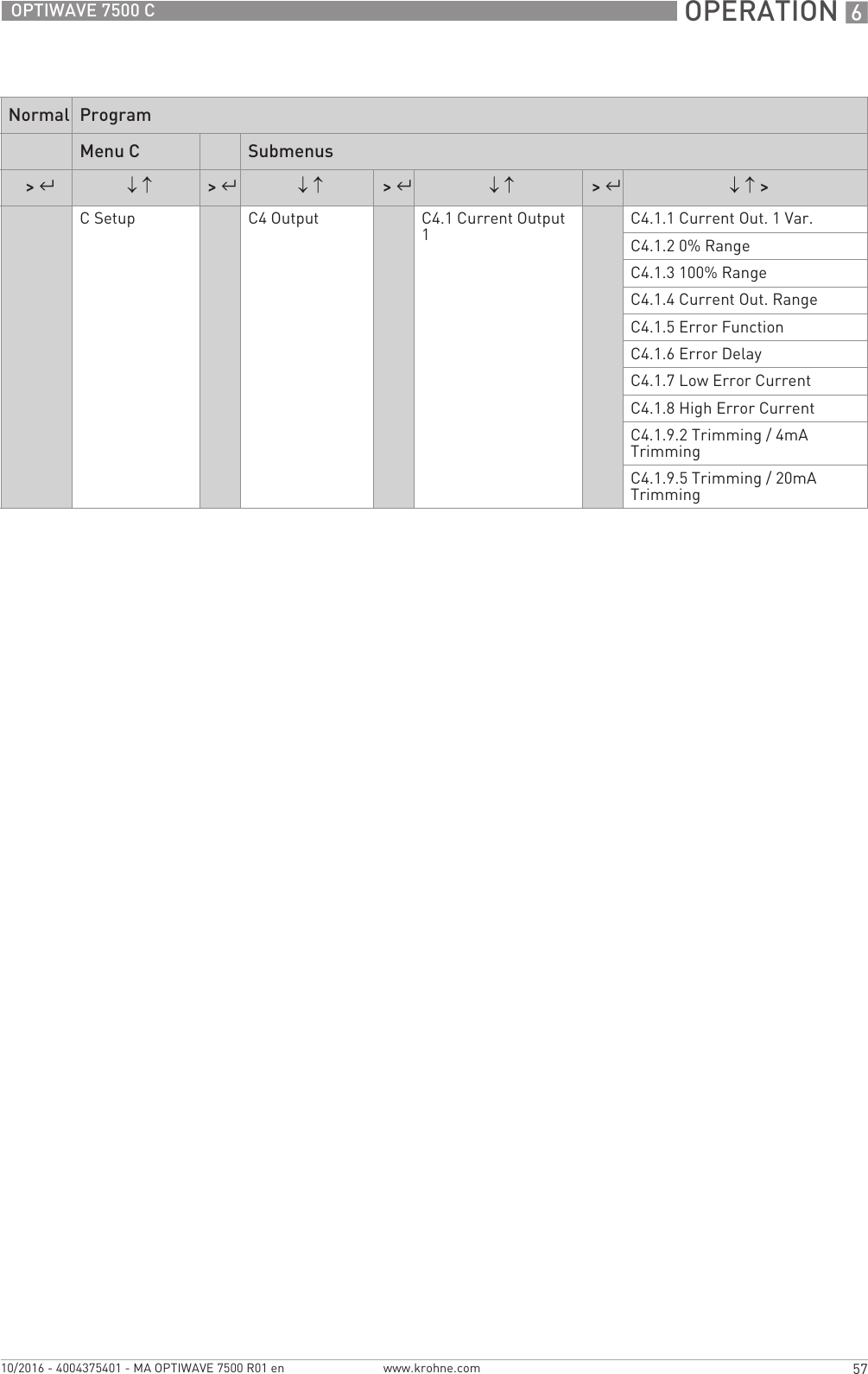
![6 OPERATION 70 OPTIWAVE 7500 Cwww.krohne.com 10/2016 - 4004375401 - MA OPTIWAVE 7500 R01 enC3.2.4 Level Enter the level value for the point given in C3.2.2. Push [^^^^] to confirm the level value and go to C3.2.5 Conv. Value.Minimum security level to do the procedure:Minimum security level to do the procedure:Minimum security level to do the procedure:Minimum security level to do the procedure: Expertmin-max:0.0...100.0+03mm / 0.0...3937.0¨0.0 mm / 0.0¨C3.2.5 Conv. Value Enter the conversion value (volume, mass or linearization) for the point given in C3.2.2. Push [^^^^] to confirm the conversion value and go back to menu C3.2.Minimum security level to do the procedure:Minimum security level to do the procedure:Minimum security level to do the procedure:Minimum security level to do the procedure: Expertmin-max:Volume: 0.0...100.0+09m³/ 0.0...26.417+12galMass: 0.0...100.0+09kg / 0.0...220.46+09lbLinearization: 0.0...100.0+12mm / 0.0...3.937+12¨Volume:0.0 m³/ 0.0 galMass:0.0 kg / 0.0 lbLinearization: 0.0 mm / 0.0¨C4 OutputC4.1 Current Output 1C4.1 Current Output 1C4.1 Current Output 1C4.1 Current Output 1C4.1.1 Current Out. 1 Var. Make a selection from the available output functions to scale the current output values. This is not shown in the normal mode.Minimum security level to change the Minimum security level to change the Minimum security level to change the Minimum security level to change the setting:setting:setting:setting: ExpertLevel, Sensor Value, Reflection, Lin. Distance, Lin. Level, DistanceDistanceC4.1.2 0% Range Give a measurement value to 0% output (refer also to C4.1.1 Current Out. 1 Var for the output function). This is the minimum loop current (this does not include the error current). The parameter set in menu item C.4.1.4 Current Out. RangeC.4.1.4 Current Out. RangeC.4.1.4 Current Out. RangeC.4.1.4 Current Out. Range has an effect on this current value.Minimum security level to change the Minimum security level to change the Minimum security level to change the Minimum security level to change the setting:setting:setting:setting: Expertmin-max:-4.9+06...+5.1+06mm / -192.91+03...+200.79+03¨0.0 mmC4.1.3 100% Range Give a measurement value to 100% output (refer also to C4.1.1 Current Out. 1 Var for the output function). This is the maximum loop current (this does not include the error current). The parameter set in menu item C.4.1.4 Current Out. RangeC.4.1.4 Current Out. RangeC.4.1.4 Current Out. RangeC.4.1.4 Current Out. Range has an effect on this current value.Minimum security level to change the Minimum security level to change the Minimum security level to change the Minimum security level to change the setting:setting:setting:setting: Expertmin-max:-4.9+06...+5.1+06mm / -192.91+03...+200.79+03¨10000 mmC4.1.4 Current Out. Range This menu item sets the limits of the output current range to 1 of 4 available options: standard limits (4...20 mA), NAMUR NE 43-compliant limits (3.8...20.5 mA), reversed standard limits and reversed NAMUR NE 43-compliant limits. You use standard limits when you want the 0% output to be 3.8 or 4 mA and the 100% output to be 20 mA or 20.5m A. You use reversed limits when you want the 0% output to be to be 20 mA or 20.5 mA and 100% output to be 3.8 mA or 4mA.Minimum security level to change the Minimum security level to change the Minimum security level to change the Minimum security level to change the setting:setting:setting:setting: Expert4-20 mA, 3.8-20.5 mA (NAMUR), 4-20 mA (reversed), 3.8-20.5 mA (reversed)4-20 mAMenu No.Function Function description Selection list Default](https://usermanual.wiki/KROHNE/FMCW80G74TA/User-Guide-3267690-Page-70.png)
![OPERATION 677OPTIWAVE 7500 Cwww.krohne.com10/2016 - 4004375401 - MA OPTIWAVE 7500 R01 enC7.2.2 Change Password This changes the password for the "operator" and "expert" security levels. For the procedure to change the password, refer to Protection of the device settings (security levels) on page 47 (How to change the password).4-digit hexadecimal password Refer to "Function description"C7.2.3 Reset Passwords This makes the passwords for the "operator" and "expert" security levels go back to the default passwords.—E8ECC7.2.4 Unlock Extended Range This menu item can only be unlocked at the factory. — —C7.2.5 Unlock SIL This menu item can only be unlocked at the factory. — —C7.3 ErrorsC7.3 ErrorsC7.3 ErrorsC7.3 ErrorsC7.3.1 Message View A log of device errors. Scroll down the list and push [>>>>] to show the error details. The error will have a letter code ("F", "S", "M", "C" and "I") that agrees with NAMUR NE 107 Guidelines.Ready only —C7.3.2 Error-MappingC7.3.2.1 Sensor: Information This permits you to change the error code that is given to an incident.Minimum security level to change the Minimum security level to change the Minimum security level to change the Minimum security level to change the setting:setting:setting:setting: UserNone, Information (I), Maintenance Request (M), Out of Specification (S), Function Check (C), Failure (F)InformationC7.5 UnitsC7.5.1 Length Unit The length unit shown in normal mode. If you set this menu item to "Cst." (custom length unit), enter values in menu items C7.5.2.1 thru C7.5.2.3.Minimum security level to change the Minimum security level to change the Minimum security level to change the Minimum security level to change the setting:setting:setting:setting: Userm, cm, mm, ft, in, Cst. mC7.5.2 Cst. LengthC7.5.2.1 Text Enter a text (8 characters maximum) for the custom length unit. —Cst.C7.5.2.2 Offset Enter an offset value. —0.0 mC7.5.2.3 Factor Enter an offset factor. Multiply the value in C7.5.4.3 Offset by this offset factor to change m (metres) to the custom length unit.—1.0C7.5.3 Volume The volume unit shown in normal mode if you made a volume table in the C3 Conversion menu. If you set this menu item to "Cst. Volume" (custom volume unit), enter values in menu items C7.5.4.1 thru C7.5.4.3.Minimum security level to change the Minimum security level to change the Minimum security level to change the Minimum security level to change the setting:setting:setting:setting: Userm³, L, hL, in³, ft³, gal, ImpGal, yd³, bbl, bbl (beer, US), Cst. Volumem³C7.5.4 Cst. VolumeC7.5.4.1 Text Enter a text (8 characters maximum) for the custom volume unit. —Cst.C7.5.4.2 Offset Enter an offset value. —0.0 m³Menu No.Function Function description Selection list Default](https://usermanual.wiki/KROHNE/FMCW80G74TA/User-Guide-3267690-Page-77.png)
![6 OPERATION 78 OPTIWAVE 7500 Cwww.krohne.com 10/2016 - 4004375401 - MA OPTIWAVE 7500 R01 en3. Service menuC7.5.4.3 Factor Enter an offset factor. Multiply the value in C7.5.4.3 Offset by this offset factor to change m³ (cubic metres) to the custom volume unit.—1.0C7.5.5 Mass The mass unit shown in normal mode if you made a mass table in the C3 Conversion menu. If you set this menu item to "Cst. Mass" (custom mass unit), enter values in menu items C7.5.6.1 thru C7.5.6.3.Minimum security level to change the Minimum security level to change the Minimum security level to change the Minimum security level to change the setting:setting:setting:setting: Userkg, t, lb, tn.sh., tn.l., Cst. MassC7.5.6 Cst. MassC7.5.6.1 Text Enter a text (8 characters maximum) for the custom volume unit. —Cst.C7.5.6.2 Offset Enter an offset value. —0.0kgC7.5.6.3 Factor Enter an offset factor. Multiply the value in C7.5.4.3 Offset by this offset factor to change kg (kilogram) to the custom mass unit.—1.0C7.6 Factory DefaultC7.6 Factory DefaultC7.6 Factory DefaultC7.6 Factory DefaultC7.6.1 Reset to Fact. Def.? If you set this menu item to "YES", the device goes back to its initial settings (set by the manufacturer in the factory).Minimum security level to change the Minimum security level to change the Minimum security level to change the Minimum security level to change the setting:setting:setting:setting: ExpertYes, No NoC7.7 Proof Test (for use in SIL mode)C7.7 Proof Test (for use in SIL mode)C7.7 Proof Test (for use in SIL mode)C7.7 Proof Test (for use in SIL mode)C7.7.1 1Unsaved parameters will be lost!Unsaved parameters will be lost!Unsaved parameters will be lost!Unsaved parameters will be lost! If you have made changes to the settings before this test and you did not go back to normal mode to save the settings, this data will not be saved. Push [^^^^] to continue.Minimum security level to do the procedure:Minimum security level to do the procedure:Minimum security level to do the procedure:Minimum security level to do the procedure: UserReady only —C7.7.2 2Run Proof Test?Run Proof Test?Run Proof Test?Run Proof Test?This menu item starts a proof test to make sure that the device can be used in SIL mode. Push [^^^^] to continue.Yes, No NoC7.7.3 Proof TestC7.7.3.1 3Proof Test is running...Proof Test is running...Proof Test is running...Proof Test is running...At the end of the test, push [^^^^] to continue. — —C7.7.3.2 4Device will be reset now!Device will be reset now!Device will be reset now!Device will be reset now!Push [^^^^] to continue. This will restart the device. End of the "Proof Test" procedure.— —Menu No.Function Function description Selection list Default3.0.0 SERVICE Advanced settings. The settings in this menu are protected with a password. Only approved personnel can change the parameters in this menu. For more data, speak or write to your local sales office.Menu No.Function Function description Selection list Default](https://usermanual.wiki/KROHNE/FMCW80G74TA/User-Guide-3267690-Page-78.png)
![OPERATION 679OPTIWAVE 7500 Cwww.krohne.com10/2016 - 4004375401 - MA OPTIWAVE 7500 R01 en4. Master menu6.4 Further information on device configuration in program mode6.4.1 Standard SetupUse this procedure (menu item A4.1 Standard Setup) to change the length unit, tank type, tank height (this includes the stilliing well diameter and stilling well height if Tank TypeTank TypeTank TypeTank Type is set to "Stilling Well"), current output variable, 0% range, 100% range, current output range and error function. Values and parameters that can be changed are shown between the «... » marks in the illustrations that follow. Push the keypad buttons in the correct sequence:ProcedureMenu No.Function Function description Selection list Default4.0.0 MASTER Factory settings. The settings in this menu are protected with a password. Only approved personnel can change the parameters in this menu. For more data, speak or write to your local sales office.CAUTION!Make sure that you do this procedure before you use the device. The settings in this procedure have an effect on the performance of the device.Screen Steps Description•2× [>>>>], 2 × [] and [>>>>]. Default screen.Enter Program Mode and go to menu item A3 Login.•2× [>>>>], 5 × [, [>>>>], 8 × [] and [^^^^]Enter the password used at this time for the "Expert" security level. If it is the default password, refer to Protection of the device settings (security levels) on page 47.•[] and 2 × [>>>>]•[] or [] for the selection of the length unit (m, Cst., in, ft, mm or cm).•[^^^^] to confirm.Push these buttons to start the Standard Setup procedure.Length unit. Make a selection from the list of parameters.•[] or [] for the selection of the tank type ().•[^^^^] to confirm.Tank type. Make a selection from the list of parameters. .](https://usermanual.wiki/KROHNE/FMCW80G74TA/User-Guide-3267690-Page-79.png)
![6 OPERATION 80 OPTIWAVE 7500 Cwww.krohne.com 10/2016 - 4004375401 - MA OPTIWAVE 7500 R01 en•[>>>>] to change the position of the cursor.•[] to decrease the value (or move the decimal point one digit to the left) or [] to increase the value (or move the decimal point one digit to the right).•[^^^^] to confirm.Tank height. The distance from the flange face / thread stop of the tank connection down to the tank bottom. If the tank has a dish-shaped or conical bottom, the tank height is measured to a point on the tank bottom directly below the antenna.•[] or [] for the selection of the measurement name (Distance, Level, Sensor Value or Reflection, Volume (Mass), Ullage Volume (Ullage Volume).•[^^^^] to confirm.Current output 1 variable. The manufacturer sets the current output variable (for current output 1) to "Distance” before delivery.If it is necessary to measure volume, ullage volume, mass or ullage mass, refer to How to configure the device to measure volume or mass on page 86.•[>>>>] to change the position of the cursor.•[] to decrease the value (or move the decimal point one digit to the left) or [] to increase the value (or move the decimal point one digit to the right).•[^^^^] to confirm.0% range. Use this step to give the 0% output setting in the tank.Refer to the illustrations that follow. When menu item A4.1.3.1 Current Out. 1 Var.A4.1.3.1 Current Out. 1 Var.A4.1.3.1 Current Out. 1 Var.A4.1.3.1 Current Out. 1 Var. is set to "Level", illustration 1 shows the position of 0% output as a level above the tank bottom. When menu item A4.1.3.1 Current A4.1.3.1 Current A4.1.3.1 Current A4.1.3.1 Current Out. 1 Var.Out. 1 Var.Out. 1 Var.Out. 1 Var. is set to "Distance", illustration 2 shows the position of 0% output as a distance below the flange facing or thread stop of the process connection.Screen Steps Description](https://usermanual.wiki/KROHNE/FMCW80G74TA/User-Guide-3267690-Page-80.png)
![OPERATION 681OPTIWAVE 7500 Cwww.krohne.com10/2016 - 4004375401 - MA OPTIWAVE 7500 R01 en•[>>>>] to change the position of the cursor.•[] to decrease the value (or move the decimal point one digit to the left) or [] to increase the value (or move the decimal point one digit to the right).•[^^^^] to confirm.100% range. Use this step to give the 0% output setting in the tank. Refer to the illustrations that follow. Illustration 1 shows the settings for level. Illustration 2 shows the settings for distance.Refer to the illustrations that follow. When menu item A4.1.3.1 Current Out. 1 Var.A4.1.3.1 Current Out. 1 Var.A4.1.3.1 Current Out. 1 Var.A4.1.3.1 Current Out. 1 Var. is set to "Level", illustration 1 shows the position of 100% output as a level above the tank bottom. When menu item A4.1.3.1 Current A4.1.3.1 Current A4.1.3.1 Current A4.1.3.1 Current Out. 1 Var.Out. 1 Var.Out. 1 Var.Out. 1 Var. is set to "Distance", illustration 2 shows the position of 100% output as a distance below the flange facing or thread stop of the process connection.•[] or [] for the selection of the current output range (3.8-20.5 mA (NAMUR), 4-20 mA, 3.8-20.5 mA (reversed) or 4-20 mA (reversed).•[^^^^] to confirm.Current output range. This menu item gives current output values to the measuring range between 0% and 100% values given in the "0% range" and "100% range" steps.If you set this menu item to "3.8-20.5 mA":•0% Range = 3.8 mA•100% Range = 20.5 mAIf you set this menu item to "4-20 mA":•0% Range = 4 mA•100% Range = 20 mAIf you set this menu item to "3.8-20.5 mA (reversed)":•0% Range = 20.5 mA•100% Range = 3.8 mAIf you set this menu item to "4-20 mA (reversed)":•0% Range = 20 mA•100% Range = 4 mAScreen Steps Description](https://usermanual.wiki/KROHNE/FMCW80G74TA/User-Guide-3267690-Page-81.png)
![6 OPERATION 82 OPTIWAVE 7500 Cwww.krohne.com 10/2016 - 4004375401 - MA OPTIWAVE 7500 R01 en6.4.2 Empty spectrum recordingThe empty spectrum recording procedure is important for the performance of the device. We recommend that the tank is empty or only filled to the minimum level before you do the procedure.Use this procedure (menu item A4.2. Empty Spectrum) if there are fixed and moving objects in the tank that can cause parasitic signals. The device does a scan for objects that do not change their vertical positions in the tank (heating tubes, agitators, fuel assemblies etc.) and records the data. The device can then use this data to put the measurement signal through a filter (empty spectrum).When the empty spectrum filter is on (when menu item C2.8 Empty Spectrum Enable is set to "Enable"), it will ignore the parasitic signals. Because the device records the data from the procedure, it is also not necessary to do the procedure again if you de-energize the device.Before you do the empty spectrum recording procedure, install the device on the tank. For more data about how to install the device, refer to Installation on page 22.Values and parameters that can be changed are shown between the «... » marks in the illustrations that follow. Push the keypad buttons in the correct sequence:•[] or [] for the selection of the error function (Off, Hold, High or Low).•[^^^^] to confirm.Error Function. This sets the behaviour of current output 1 if an error occurs.If this menu item is set to "Off", no signal is given (this parameter is not available if menu item C4.1.4 is set to "3.8-20.5 mA" (NAMUR) or "3.8-20.5 mA (reversed)"). If this menu item is set to "Hold", the output current stays at the value where the error occurred (this parameter is not available if menu item C4.1.4 is set to "3.8-20.5 mA" (NAMUR) or "3.8-20.5 mA (reversed)"). If this menu item is set to "Low", the output current changes to 3.5 mA (default value) if an error occurs. If this menu item is set to "High", the output current changes to 21.5 mA (default value) if an error occurs.•3× [^^^^] to confirm.•[] or [] for the selection of the save option (Yes, No or Back).•[^^^^] to confirm.Save Configuration?Save Configuration?Save Configuration?Save Configuration? screen.Set to "Yes" to save and use the settings and data and go back to Normal Mode. Set to "No" to cancel the changes to the device settings and go back to Normal Mode. Set to "Back" to stay in Program Mode.Screen Steps DescriptionCAUTION!Make sure that the tank is empty or only filled to the minimum level.](https://usermanual.wiki/KROHNE/FMCW80G74TA/User-Guide-3267690-Page-82.png)
![OPERATION 683OPTIWAVE 7500 Cwww.krohne.com10/2016 - 4004375401 - MA OPTIWAVE 7500 R01 enProcedureScreen Steps Description•2× [>>>>], 2 × [] and [>>>>]. Default screen.Enter Program Mode and go to menu item A3 Login.•2× [>>>>], 5 × [, [>>>>], 8 × [] and [^^^^]Enter the password used at this time for the "Expert" security level. If it is the default password, refer to Protection of the device settings (security levels) on page 47.•[], [>>>>], [] and 2 × [>>>>].•[] or [] for the selection of the empty spectrum type (Full (Average), Full (Max), Partial (Average), Partial (Max)).•[^^^^] to confirm.Push these buttons to start the Record Spectrum (Empty Spectrum) procedure.Empty spectrum type. Make a selection from the list of parameters. If you can empty the tank, set this menu item to "Full, Average" or "Full, Max". If you cannot empty the tank, set this menu item to "Partial, Average" or "Partial, Max"..•[>>>>] to change the position of the cursor.•[] to decrease the value (or move the decimal point one digit to the left) or [] to increase the value (or move the decimal point one digit to the right).•[^^^^] to confirm.Partial distance. If you set Empty Spectrum Empty Spectrum Empty Spectrum Empty Spectrum TypeTypeTypeType to "Partial, Average" or "Partial, Max", you will have one more step to do in this procedure. You must give the distance (partial distance) of the product surface from the flange facing or thread stop of the process connection.•[^^^^] to confirm. Make sure that the tank is empty or it contains not more than the minimum quantity. .•[] or [] to change the parameter ("No" or "Yes".•[^^^^] to confirm.Start recording? Set this menu item to "Yes" to continue to the subsequent step. Set this menu item to "No" to go back to the menu.](https://usermanual.wiki/KROHNE/FMCW80G74TA/User-Guide-3267690-Page-83.png)
![6 OPERATION 84 OPTIWAVE 7500 Cwww.krohne.com 10/2016 - 4004375401 - MA OPTIWAVE 7500 R01 en6.4.3 HART® network configurationThe device uses HART® communication to send information to HART®-compatible equipment. It can operate in either point-to-point or multidrop mode. The device will communicate in multidrop mode if you change the polling address.How to change from point-to-point to multidrop mode• Enter Program mode.• Push 2 × [], [>>>>], 4 × [], 2 × [>>>>], [] and 2 × [>>>>] to go to menu item C5.1.2.1 Polling Adress.• Enter a value between 001 and 063 and push [^^^^] to confirm.• Push [^^^^] again and again to go back to the Save ConfigurationSave ConfigurationSave ConfigurationSave Configuration screen.• Push [] or [] to set the screen to "Yes" and push [^^^^].•[^^^^] to confirm. Graph with the results of the empty spectrum recording.•[] or [] to change the parameter ("No" or "Yes".•[^^^^] to confirm.Save spectrum? If you set the menu item to "Yes", the device will keep this empty spectrum recording. If you set the menu item to "No", the device will reject this data.•[] or [] to change the parameter ("Disable" or "Enable".•[^^^^] to confirm.Empty Spectrum Enable. If you set the menu item to "Enable", the device will use the empty spectrum recording data. If you set the menu item to "Disable", the device will not use the empty recording data at this time.•4× [^^^^] to confirm.•[] or [] for the selection of the save option (Yes, No or Back).•[^^^^] to confirm.Save Configuration?Save Configuration?Save Configuration?Save Configuration? screen.Set to "Yes" to save and use the settings and data and go back to Normal Mode. Set to "No" to cancel the changes to the device settings and go back to Normal Mode. Set to "Back" to stay in Program Mode.INFORMATION!For more data, refer to Networks on page 37.Screen Steps DescriptionCAUTION!Make sure that the address for this device is different from others in the multidrop network.](https://usermanual.wiki/KROHNE/FMCW80G74TA/User-Guide-3267690-Page-84.png)
![OPERATION 685OPTIWAVE 7500 Cwww.krohne.com10/2016 - 4004375401 - MA OPTIWAVE 7500 R01 eniThe output is set to multidrop mode. The current output is set to 4 mA. This value does not change in multidrop mode.How to change from multidrop to point-to-point mode• Enter Program mode.• Push 2 × [], [>>>>], 4 × [], 2 × [>>>>], [] and 2 × [>>>>] to go to menu item C5.1.2.1 Polling Address.• Enter the value 000 and push [^^^^] to confirm.• Push [^^^^] again and again to go back to the Save ConfigurationSave ConfigurationSave ConfigurationSave Configuration screen.• Push [] or [] to set the screen to "Yes" and push [^^^^].iThe output is set to point-to-point mode. The current output changes to a range of 4...20 mA or 3.8...20.5 mA (this range is set in menu item C4.1.4 Current Out. Range).6.4.4 Distance measurementMenu items related to distance measurement are:•Current output 1 menu (C4.1)•Tank Height (C1.2 – if C1.1 Tank Type is set to 'Storage", "Process" or Agitator") or Stilling Well Height (C1.3 – if C1.1 Tank Type is set to "Stilling Well")•Blocking Distance (C1.5)6.4.5 Level measurementMenu items related to level measurement are:•Current output 1 menu (C4.1)•Tank Height (C1.2 – if C1.1 Tank Type is set to 'Storage", "Process" or Agitator") or Stilling Well Height (C1.3 – if C1.1 Tank Type is set to "Stilling Well")•Blocking Distance (C1.5)INFORMATION!Reference OffsetReference OffsetReference OffsetReference OffsetIf you move the reference point above the flange, add this value when you give a distance for the 0% Range and 100% Range settings. If you move the reference point below the flange, subtract this value when you give a distance for the 0% Range and 100% Range settings.CAUTION!If the distance for 0% Range (standard scale) is set in the blocking distance, it is possible that the device will not be able to use the full current output range.INFORMATION!Tank Bottom OffsetTank Bottom OffsetTank Bottom OffsetTank Bottom OffsetIf you move the tank bottom offset below the tank bottom (or the bottom of the stilling well), add this value when you give a level for the 0% Range and 100% Range settings. If you move the tank bottom offset above the tank bottom (or the bottom of the stilling well), subtract this value when you give a level for the 0% Range and 100% Range settings.CAUTION!If the distance for 100% Range (standard scale) is set in the blocking distance, it is possible that the device will not be able to use the full current output range.](https://usermanual.wiki/KROHNE/FMCW80G74TA/User-Guide-3267690-Page-85.png)
![6 OPERATION 86 OPTIWAVE 7500 Cwww.krohne.com 10/2016 - 4004375401 - MA OPTIWAVE 7500 R01 en6.4.6 How to configure the device to measure volume or massThe device can be configured to measure volume or mass. It can also be configured to a custom quantity to be measured. You can set up a strapping table in the conversion menu (C3 Conversion). Each entry is a pair of data (level – volume, level – mass or level – custom measurement). The strapping table must have a minimum of 2 entries and a maximum of 50. The reference point for the table is the bottom of the tank (as given in menu item Tank Height (C1.2) or Stilling Well Height (C1.3)How to prepare a strapping table (conversion table)• Enter Program Mode.• Push 2 × [], [>>>>], 6 × [], [>>>>], 3 × [] and 3 × [>>>>] to go to C7.5.1 Length Unit.• Push [] and [] to find the length unit that you will use in the table.• If it is necessary to make a volume table, push [^^^^] to go back to the sub-menu level and then push 2 × [] and [>>>>] to go to C7.5.3 Volume.• Push [] and [] to find the volume unit that you will use in the table.• Push 3 × [^^^^] to go to the sub-menu level and then 4 × [], 2 × [>>>>] to delete strapping table data that the device uses at this time (Erase Table?). Push [] and [] to set this menu item to "Yes" to delete the data.• Push [^^^^] and then [] and [] to make a selection from the conversion table options (volume, mass linearization).• Push [^^^^] to go to the sub-menu level and then [] and [>>>>] to enter the first point on the table.• Push [^^^^] to make the strapping table.• Enter the length value and push [^^^^].• Enter the conversion value and push [^^^^] to go to the sub-menu level.• Push [>>>>] to enter the subsequent point (02, 03, ..., 50) on the table.• Repeat the last 3 steps to complete the table.• If the table is complete, push [^^^^] again and again to go back to the "Save Configuration?" screen.• The device will ask you to save or cancel your settings. Push [] or [] to make a selection from YesYesYesYes, NoNoNoNo or BackBackBackBack. BackBackBackBack makes the display go back to Program mode. If this screen is set to "Yes" or No", push [^^^^] to accept (Yes) or reject (No) the new settings.iIf you push [^^^^] when the screen is set to "Yes", the device will store the data for the strapping table and go back to normal mode.The device will give more accurate volume readings if you give more conversion data in these areas:•Surfaces with curves.•Sudden changes in the cross section.Refer also to the illustration that follows:CAUTION!Enter the data in numerical sequence (strapping table entry number 01, 02 etc.).](https://usermanual.wiki/KROHNE/FMCW80G74TA/User-Guide-3267690-Page-86.png)
![OPERATION 687OPTIWAVE 7500 Cwww.krohne.com10/2016 - 4004375401 - MA OPTIWAVE 7500 R01 enHow to delete a volume or mass table• Enter Program Mode.• Push 2 × [], [>>>>], 2 × [] and 2 × [>>>>] to go to C3.1.1 Erase Table?.• To delete strapping table data that the device uses at this time (Erase Table?), push [] and [] to set this menu item to "Yes".• Push [^^^^] again and again to go back to the "Save Configuration?" screen.• The device will ask you to save or cancel your settings. Push [] or [] to make a selection from YesYesYesYes, NoNoNoNo or BackBackBackBack. BackBackBackBack makes the display go back to Program mode. If this screen is set to "Yes" or No", push [^^^^] to accept (Yes) or reject (No) the new settings.iIf you push [^^^^] when the screen is set to "Yes", the device will delete the data for the strapping table and go back to normal mode.6.4.7 How to make a filter to remove radar signal interference6.4.8 You can offset the tank bottom reference point to find the delayed radar reflection. Obey the instructions that follow:Figure 6-7: A plot of points for a volume or mass table1 2 INFORMATION!.INFORMATION!](https://usermanual.wiki/KROHNE/FMCW80G74TA/User-Guide-3267690-Page-87.png)
![TECHNICAL DATA 8101OPTIWAVE 7500 Cwww.krohne.com10/2016 - 4004375401 - MA OPTIWAVE 7500 R01 enFlange, EN 1092-1 DN25 in PN10, PN16, PN25, PN40, PN63 or PN100 (Type B1); others on requestFlange, ASME B16.5 1¨ in 150 lb, 300 lb or 600 lb RF; others on requestLens antenna, Ø40 mmLens antenna, Ø40 mmLens antenna, Ø40 mmLens antenna, Ø40 mmHygienic BioControl® DN50; Tri-Clamp® 2¨; others on requestFlange, EN 1092-1 DN40...80 in PN10, PN16, PN25, PN40, PN63 or PN100 (Type B1); others on requestFlange, ASME B16.5 1½¨...3¨ in 150 lb, 300 lb or 600 lb RF; others on requestElectrical connectionsPower supply Terminals output Terminals output Terminals output Terminals output – Non-Ex / Ex i: Non-Ex / Ex i: Non-Ex / Ex i: Non-Ex / Ex i:12…30 VDC; min./max. value for an output of 21.5 mA at the terminalTerminals output Terminals output Terminals output Terminals output – Ex d: Ex d: Ex d: Ex d:14…36 VDC; min./max. value for an output of 21.5 mA at the terminalMaximum current 21.5 mACurrent output load Non-Ex / Ex i:Non-Ex / Ex i:Non-Ex / Ex i:Non-Ex / Ex i: RL [Ω] ≤ ((Uext -12V)/21.5mA). For more data, refer to Minimum power supply voltage on page 103.Ex d:Ex d:Ex d:Ex d: RL [Ω] ≤ ((Uext -14 V)/21.5 mA). For more data, refer to Minimum power supply voltage on page 103.Cable entry Standard: M20×1.5; Option: ½NPTCable gland Standard: noneOptions: M20×1.5 (cable diameter: 7…12 mm / 0.28…0.47¨); others are available on requestCable entry capacity (terminal) 0.5…3.31 mm² (AWG 20...12)Input and outputCurrent output / HARTCurrent output / HARTCurrent output / HARTCurrent output / HART®Output signal 4…20 mA HART®, 4…20 mA HART® (reversed), 3.8…20.5 mA or 3.8…20.5 mA (reversed) acc. to NAMUR NE 43 2Resolution ±3µATemperature drift Typically 50 ppm/KError signal High: 21.5 mA; Low: 3.5 mA acc. to NAMUR NE 43Approvals and certificationCE This device fulfils the statutory requirements of the EC directives. The manufacturer certifies successful testing of the product by applying the CE mark.Vibration resistance EN 60068-2-6 and EN 60721-3-4 (1...9 Hz: 3 mm / 10...200 Hz:1g, 10g shock ½ sinus: 11 ms)Explosion protectionExplosion protectionExplosion protectionExplosion protectionATEX (Ex ia or Ex d)DEKRA xxATEXxxxx X(pending)II 1/2 G, 2 G Ex ia IIC T6...T2 Ga/Gb or Ex ia IIC T6...T2 Gb;II 1/2 D, 2 D Ex ia IIIC T90°C Da/Db or Ex ia IIIC T90°C Db IP6X;II 1/2 G, 2 G Ex d ia IIC T6...T2 Ga/Gb or Ex d ia IIC T6...T2 Gb;II 1/2 D, 2 D Ex ia tb IIIC T90°C Da/Db or Ex ia tb IIIC T90°C Db IP6XATEX (Ex ic)DEKRA xxATEXxxxx X(pending)II 3 G Ex ic IIC T6...T2 Gc;II 3 D Ex ic IIIC T90°C Dc](https://usermanual.wiki/KROHNE/FMCW80G74TA/User-Guide-3267690-Page-101.png)
![8 TECHNICAL DATA 102 OPTIWAVE 7500 Cwww.krohne.com 10/2016 - 4004375401 - MA OPTIWAVE 7500 R01 enIECExIECEx DEK xx.xxxx X(pending) Ex ia IIC T6…T2 Ga/Gb or Ex ia IIC T6…T2 Gb or Ex ic IIC T6…T2 Gc;Ex ia IIIC T90°C Da/Db or Ex ia IIIC T90°C Db or Ex ic IIIC T90°C Dc;Ex d ia IIC T6...T2 or Ex d ia IIIC T6...T2 Gb;Ex ia tb IIIC T90°C Da/Db or Ex ia tb IIIC T90°C DbcQPSus – Dual Seal-approved(pending) NEC 500 (Division ratings)NEC 500 (Division ratings)NEC 500 (Division ratings)NEC 500 (Division ratings)XP-AIS / Cl. I / Div. 1 / Gr. ABCD / T6-T1;DIP / Cl. II, III / Div. 1 / Gr. EFG / T6-T1;IS / Cl. I, II, III / Div. 1 / Gr. ABCDEFG / T6-T1;NI / Cl. I / Div. 2 / Gr. ABCD / T6-T1NEC 505 (Zone ratings)NEC 505 (Zone ratings)NEC 505 (Zone ratings)NEC 505 (Zone ratings)Cl. I / Zone 0 / AEx d [ia] / IIC / T6-T1;Cl. I / Zone 0 / AEx ia / IIC / T6-T1;Cl. I / Zone 2 / AEx nA / IIC / T6-T1;Zone 20 / AEx ia / IIIC / T90°CZone 20 / AEx tb [ia] / IIIC / T90°CHazardous (Classified) Locations, indoor/outdoor Type 4X and 6P, IP66, Dual SealCEC Section 18 (Zone ratings)CEC Section 18 (Zone ratings)CEC Section 18 (Zone ratings)CEC Section 18 (Zone ratings)Cl. I, Zone 0, Ex d [ia], IIC, T6-T1;Cl. I, Zone 0, Ex ia, IIC, T6-T1;Cl. I, Zone 2, Ex nA, IIC, T6-T1CEC Section 18 and Annex J (Division ratings)CEC Section 18 and Annex J (Division ratings)CEC Section 18 and Annex J (Division ratings)CEC Section 18 and Annex J (Division ratings)XP-AIS / Cl. I / Div. 1 / Gr. BCD / T6-T1DIP / Cl. II, III / Div. 1 / Gr. EFG / T6-T1IS/ Cl.I/ Div.1/ Gr.BCD/ T6-T1NI / Cl. I / Div. 2 / Gr. ABCD / T6-T1NEPSIGYJxxxxxx/xx(pending)Ex ia IIC T2~T6 Gb or Ex ia IIC T2~T6 Ga/Gb DIP A20/A21 TA T90°C IP6XEx d ia IIC T2~T6 Gb or Ex d ia IIC T2~T6 Ga/Gb DIP A20/A21 TA T90°C IP6XDNV / INMETRODNV 14.00xx X(pending)Ex ia IIC T6…T3 Ga; Ex ia IIIC T70°C...T95°C Da IP6X;Ex d [ia Ga] IIC T6...T3 Ga/Gb; Ex tb [ia Da] IIIC T70°C...T95°C Db IP6XOther standards and approvalsOther standards and approvalsOther standards and approvalsOther standards and approvalsSIL- only for 4...20 mA HART output 4...20 mA HART output only: SIL 2 – according to EN 61508 and for high/low demand mode operationEMC Electromagnetic Compatibility Directive 2004/108/ECRadio approvals R & TTER & TTER & TTER & TTERadio Equipment and Telecommunications Terminal Equipment Directive 1999/5/ECFCC RulesFCC RulesFCC RulesFCC RulesPart 15Industry CanadaIndustry CanadaIndustry CanadaIndustry CanadaRSS-211LVD Agrees with the safety part of the Low-Voltage Directive 2006/95/EC](https://usermanual.wiki/KROHNE/FMCW80G74TA/User-Guide-3267690-Page-102.png)
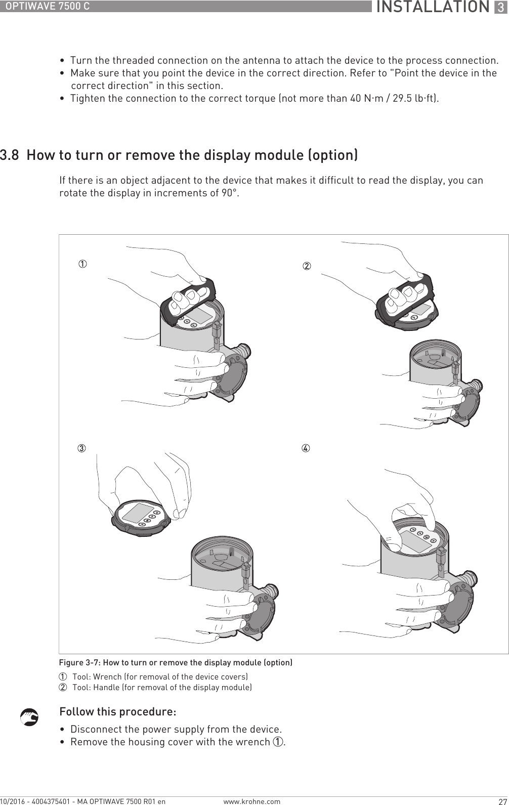
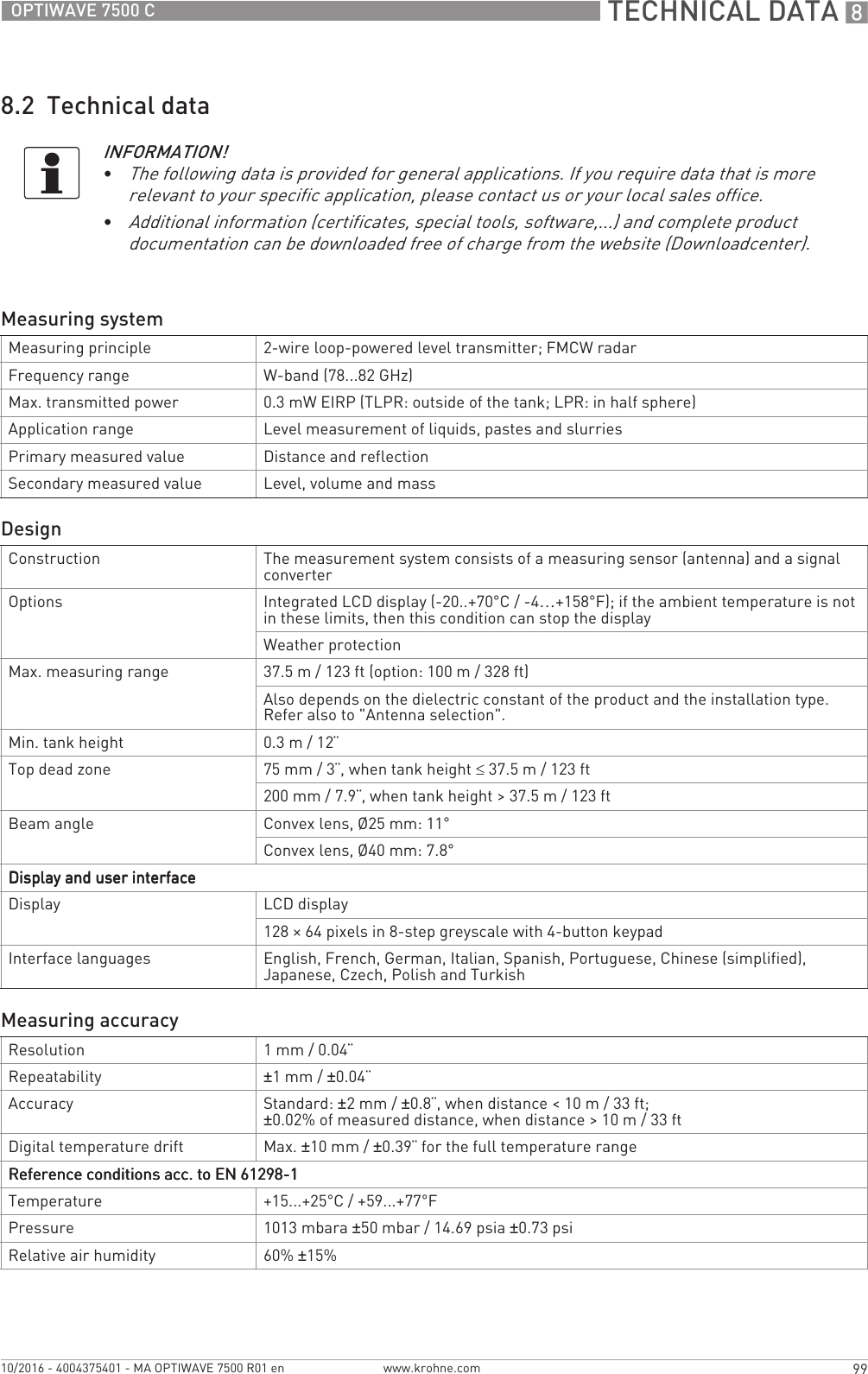
![TECHNICAL DATA 8103OPTIWAVE 7500 Cwww.krohne.com10/2016 - 4004375401 - MA OPTIWAVE 7500 R01 en8.3 Minimum power supply voltageUse these graphs to find the minimum power supply voltage for a given current output load.NAMUR NAMUR NE 21 Electromagnetic Compatibility (EMC) of Industrial Process and Laboratory Control EquipmentNAMUR NE 43 Standardization of the Signal Level for the Failure Information of Digital TransmittersNAMUR NE 53 Software and Hardware of Field Devices and Signal Processing Devices with Digital ElectronicsNAMUR NE 107 Self-Monitoring and Diagnosis of Field DevicesCRN This certification is applicable for all Canadian provinces and territories. For more data, refer to the website.Construction code Option: NACE MR 0175 / MR 0103 / ISO 151561Tri-Clamp® is a registered trademark of Ladish Co., Inc. BioControl® is a registered trademark of Neumo-Ehrenberg-Group. VARIVENT® is a registered trademark of GEA Tuchenhagen GmbH.2HART® is a registered trademark of the HART Communication FoundationFigure 8-2: Minimum power supply voltage for an output of 22 mA at the terminal (Non-Ex and Hazardous Location approval (Ex i / IS))X: Power supply U [VDC]Y: Current output load RL [Ω]](https://usermanual.wiki/KROHNE/FMCW80G74TA/User-Guide-3267690-Page-103.png)
![8 TECHNICAL DATA 104 OPTIWAVE 7500 Cwww.krohne.com 10/2016 - 4004375401 - MA OPTIWAVE 7500 R01 en8.4 Guidelines for maximum operating pressureHazardous Location (Ex d / XP/NI) approved devicesFigure 8-3: Minimum power supply voltage for an output of 22 mA at the terminal (Hazardous Location approval (Ex d / XP/NI))X: Power supply U [VDC]Y: Current output load RL [Ω]WARNING!Make sure that the devices are used within their operating limits.Figure 8-4: Pressure / temperature de-rating (EN 1092-1), flange and threaded connection, in °C and barg-50 0 50 100 150 200010203040506070809010020](https://usermanual.wiki/KROHNE/FMCW80G74TA/User-Guide-3267690-Page-104.png)

![8 TECHNICAL DATA 106 OPTIWAVE 7500 Cwww.krohne.com 10/2016 - 4004375401 - MA OPTIWAVE 7500 R01 enAntenna option weightsType of housing WeightsAluminium housing Stainless steel housing[kg] [lb] [kg] [lb]Compact 2.1 4.6 ?? ??Antenna options Min./Max. weights[kg] [lb]Standard options, without converterStandard options, without converterStandard options, without converterStandard options, without converterDN50 / 2¨ Hygienic antenna with clamp connection ??...?? ??...??DN50 / 2¨ Hygienic antenna with thread connection ??...?? ??...??](https://usermanual.wiki/KROHNE/FMCW80G74TA/User-Guide-3267690-Page-106.png)