KROHNE OPTIWAVE7300CI Radar Level Meter User Manual aussen 6 x A5 Page 6
Krohne America Inc Radar Level Meter aussen 6 x A5 Page 6
KROHNE >
Exhibit 8 user manual
©KROHNE 04/2004 7.02287.21.00
CH
OPTIWAVE 7300 C
Radar Level Meter
Measurement of distance,
level and volume of liquids,
pastes and solids
• Easy installation
• Wizard driven
• Service and maintenance-free
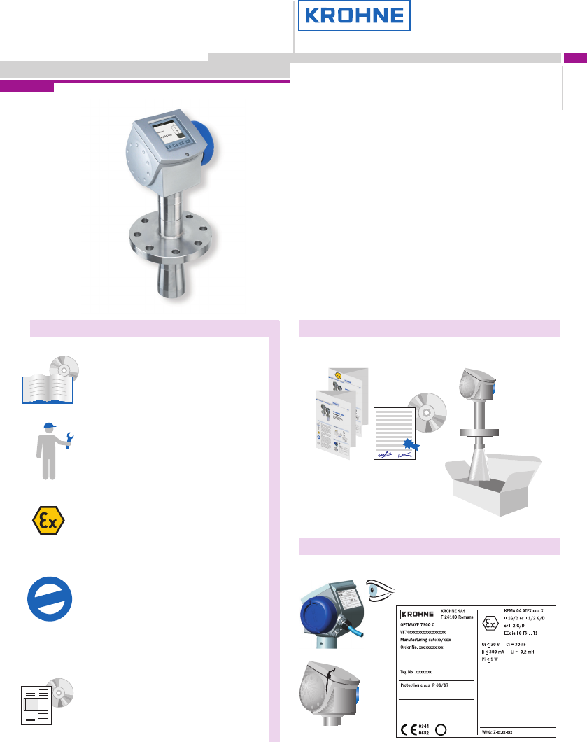
General Items supplied
Visual check
This is a quick-start guide only. For further infor-
mation please consult the handbook, data sheet,
special manuals and certificates supplied on
CD-ROM.
Installation, assembly, commissioning and ser-
vicing must only be undertaken by trained
personnel. Maintenance which is considered
relevant to safety in the sense of explosion pro-
tection must only be carried out by the manu-
facturer, his agents or under the supervision of
experts.
For use in hazardous areas, special codes and
regulations are applicable, which are supplied in
a separate document that describes all ATEX
hazardous area information.
Responsibility as to suitability and intended use
of this device rests solely with the user. The sup-
plier does not accept any liability resulting from
misuse by the customer. Improper installation
and operation of our level gauges may lead to
loss of warranty. In addition, the "General condi-
tions of sale", found on the back of the invoice
and forming the basis of the purchasing con-
tract, are applicable.
If you need to return the device to the manufac-
turer or supplier, please complete the form
given on the CD-Rom and attach to the device.
KROHNE regrets that it cannot repair or check
your device unless accompanied by this com-
pleted form.
*
Warranty
*If applicable
Quick-start
Quick-start OPTIWAVE 7300 C
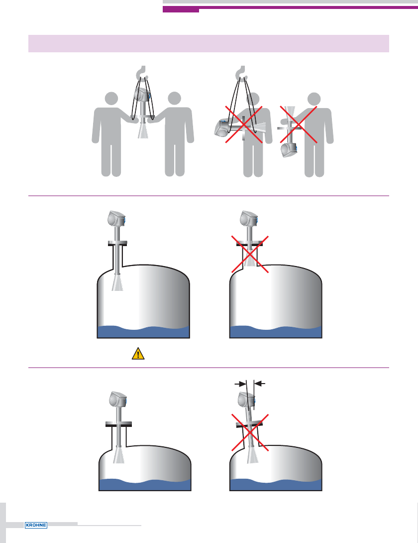
Handling and installation instructions
2
max. 2°
Antenna must protrude from nozzle base.
Handling and installation instructions
3
Option
H
D
Mount off-centre
to avoid multiple
reflections.
DN 40 / 50:
> 1/7 H, but max. 1/3 D
DN 80:
> 1/10 H, but max. 1/3 D
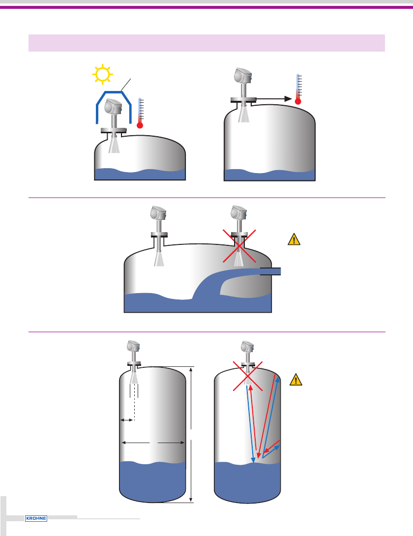
Install away from
entry pipe.
+80°C / +175°F
-40°C / -40°F
max. 150°C / 300°F
min. -40°C / -40°F Viton
min. -20°C / -5°F Kalrez
Special considerations
4
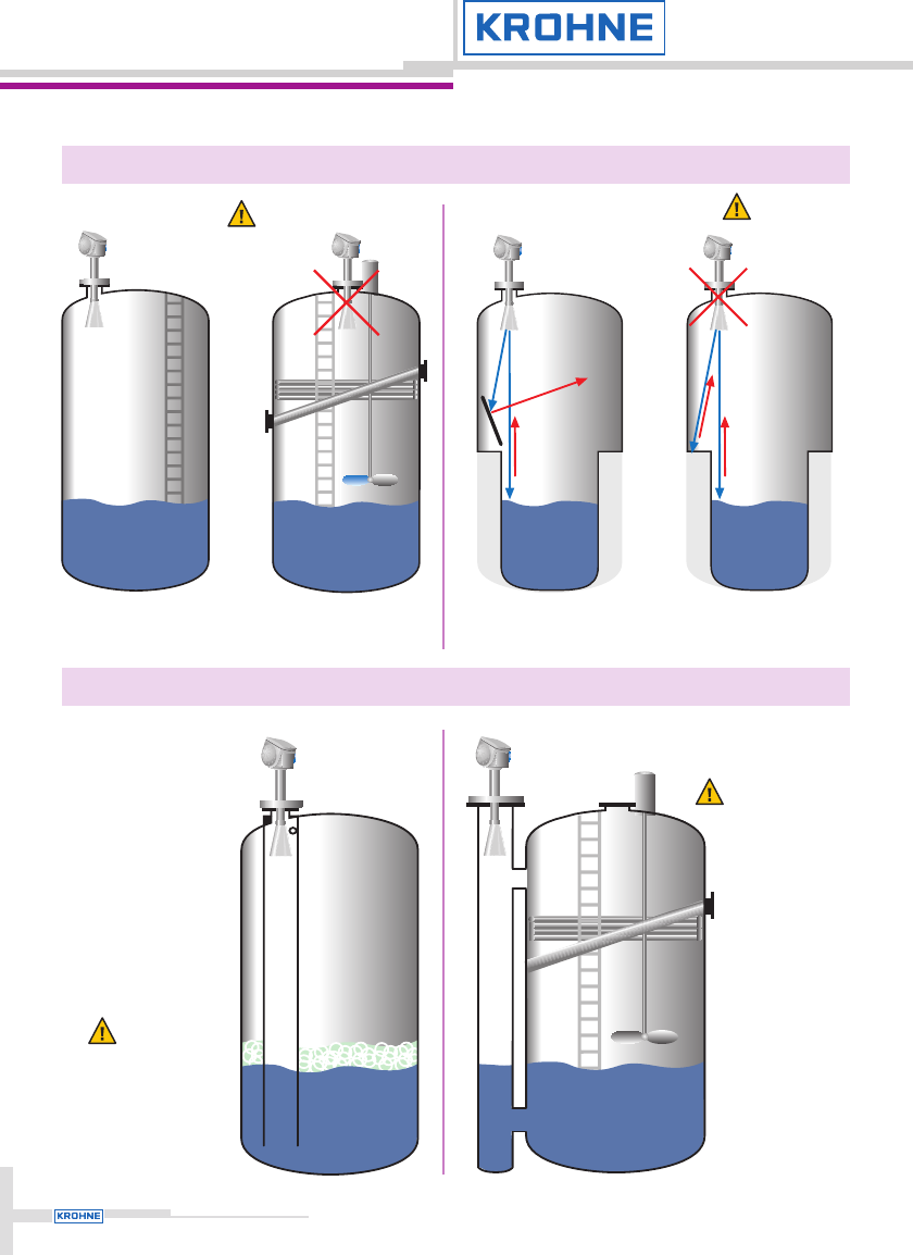
Stray
reflections!
Too many
objects in tank:
use bypass
chamber
Foam:
use stilling well
Avoid too many objects
near to the radar beam
in tank.
Stilling wells and bypass chambers
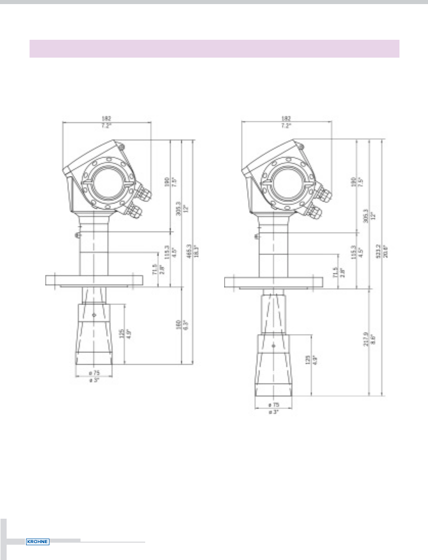
Dimensions and Weights
5
Note:
Additional antenna extension of
105 mm / 4.1" length available.
approx. 11 kg /24.3 lb
Flange (Antenna DN 80) Antenna DN 80 with antenna extension
approx. 12 kg /26.5 lb
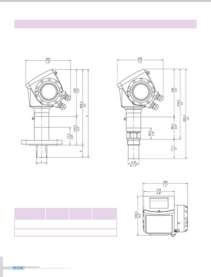
Dimensions and Weights
6
Dimensions in mm and inch
Flange (Antenna DN 40/50) Thread
39 / 1.5
43 / 1.7
38.5 / 1.5
50 / 2
343.8 / 13.5
355.3 / 14
cba
Antenna type
Antenna DN 40
Antenna DN 50
mm / inch mm / inch mm / inch
Note:
Cable glands are not delivered
with the device.
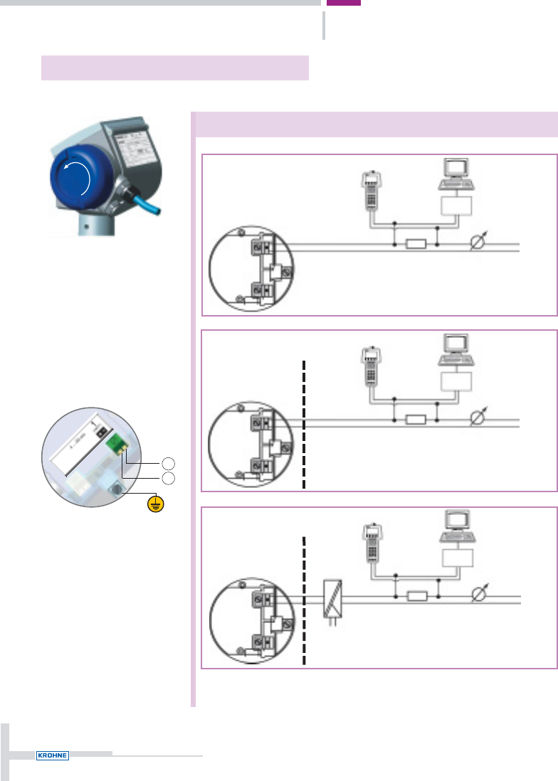
Terminal Compartment and Terminals
7
Wiring options
min.250ΩL –
L +
HART®
Configuration
Software
HART®
Modem
HHC
Non-Ex
min.250ΩL –
L +
HART®
Configuration
Software
HART®
Modem
HHC
Intrinsically Safe (IS) / Ex i
min.250ΩL –
L +
HART®
Configuration
Software
HART®
Modem
HHC
Explosion Proof (XP) / Ex d
Ex non-Ex
Ex non-Ex
Note: Other options how to connect the HHC and modem to the
HART®loop are available.
Output 1
4 ... 20 mA/HART
or
3.8 ... 20.5 mA/HART
acc. to NAMUR NE 43
–
+
Connection procedure
•Unscrew terminal
compartment cover.
•Wire up using standard
procedures.
•Apply grease to thread
of cover before closing.

Quick-start OPTIWAVE 7300 C
Technical data extract
Application conditions
Temperature
Ambient temperature -40…+80°C / -40…+175°F;
EEx i: -40…+60°C / -40…+140°F
Storage temperature -40…+85°C / -40…+185°F
Flange temperature -40…+150°C / -40…+300°F (Viton gasket)
-20…+150°C / -5…+300°F (Kalrez 6375 gasket)
Thermal shock resistance 100°C/min
Process conditions
Operating pressure -1…40 bar / -14.5…580 psig;
subject to process connection used and flange
temperature
Dielectric constant 1.5
Vibration resistance IEC 68-2-6 and prEN 50178
(10...57Hz: 0.075 mm / 57...150 Hz: 1 g)
Protection category IP 66/67 equiv. to NEMA 6-6X
Output
Output signal
Output 1 4 … 20 mA HART® or 3.8 … 20.5 mA
acc. to NAMUR NE 43
Accuracy 0.05% (rel. 20 mA; 20°C / 68°F)
Resolution ±2 µA
Temperature drift Typically 50 ppm/K
Error signal High: 22 mA; Low: 3.6 mA acc. to NAMUR NE 43
Max. Load 350 ohm
Approvals
Overfill protection WHG
ATEX ATEX II G/D 1, 1/2, 2 EEx ia IIC T6;
ATEX II G/D 1/2, 2 EEx d ia IIC T6
FM IS class I Div. 1 Gr. A...G; XP class I Div. 1 Gr. A…G
CSA IS class I Div. 1 Gr. A...G; XP class I Div. 1 Gr. A…G
For futher data see data sheet, approvals and handbook on CD-ROM
Hotline: +33(0)4.75.05.44.00 · Fax: +33(0)4.75.05.44.97
www.krohne.com for local contacts · E-mail: level@krohne.fr
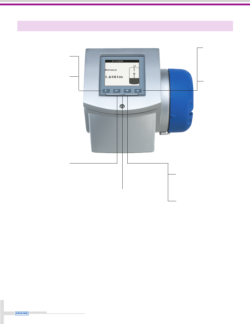
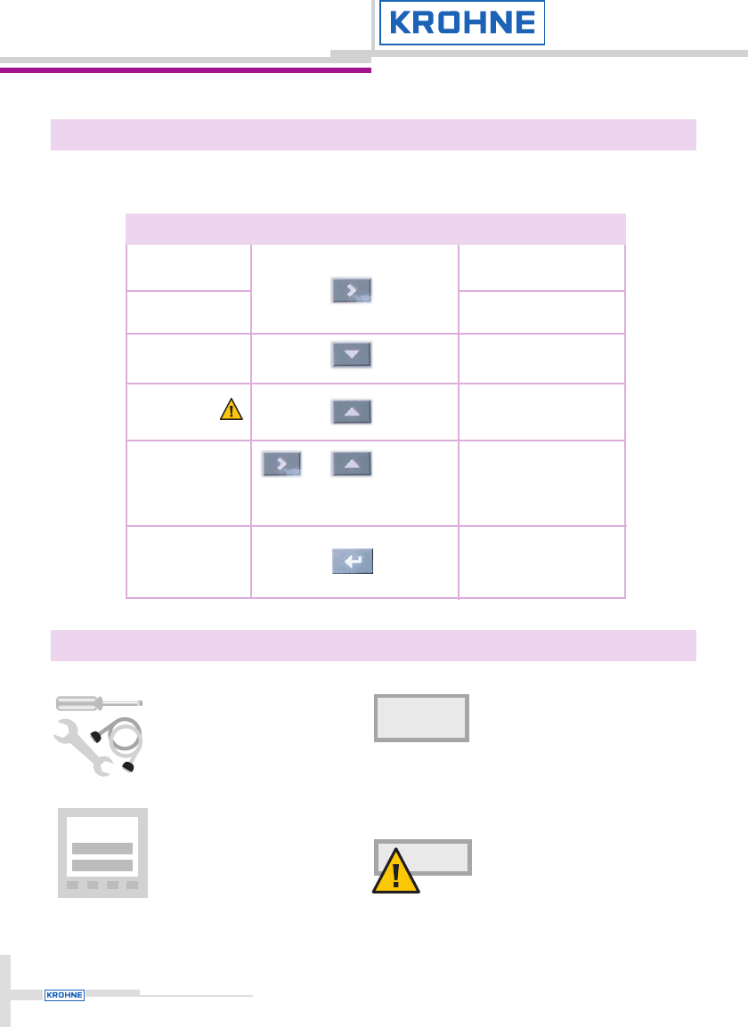
Human interface
9
Program mode:
Saves or confirms
parameter.
Program mode:
ESC-function returns to
previous menu. If top
menu reached, returns
to normal mode.
Any paramenter value
entered is not stored.
Normal mode:
Selects display style.
Program mode:
Moves cursor to right or
selects next menu level.
ESC
Normal mode:
Selects type of
information
displayed.
Program mode:
Moves menu
selector up the
list or increments
parameter value.
Normal mode:
Selects measurement
parameters to be displayed.
Program mode:
Moves menu selector down list
or decrements parameter value.
Human interface
Startup procedure
10
Hot keys
Hot key activated when:
3 seconds
3 seconds
3 seconds
3 seconds
3 seconds
Action
Enters program mode
Saves current function
used as quick link
Active screen stored as
default screen
HMI will reset to default
language
Returns to normal mode
(last screen displayed)
Signal editing function
Mode
Normal
Program
Normal
All modes
Program
Normal
(signal screen)
☞
☞
☞
☞
☞
☞
+
After mechanical and electri-
cal installation, start-up, then
the device performs a self-
test and is ready for use.
The Wizard automatically dis-
plays parameter setup steps
on-screen.
If false parameter value is input-
ted (e.g. outside limits) an error
message / icon occurs, and after
10 seconds the screen switches
to HELP function.
If error persists, download log file
using PACTware and send to e-
mail address given on back rear
page. For further information see
PACTware handbook on CD-ROM.
HELP
10 sec
?
ERROR
WIZARD
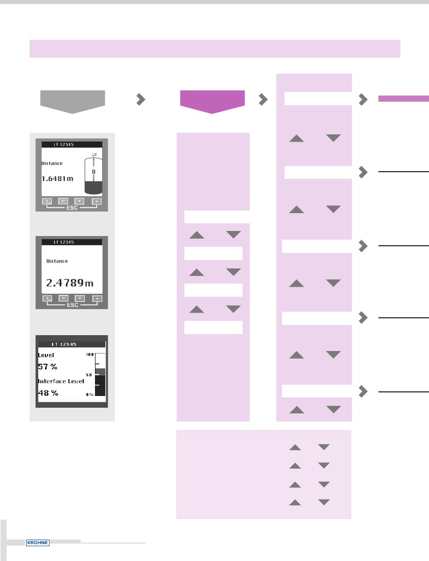
Complete
Installation
Empty Spectrum
Conversion
Output
Setup procedure
11
Quick setup
Test
Advanced setup
Service
Quick link #1
Quick link #2
Quick link #3
Quick link #4
Quick link #5
Press 3 sec
Normal Mode Program Mode
Quick links
The customer can assign
any menu point to one of
the quick links (including
overwriting factory presets)
to avoid going through full
setup proce-dure.
Access to default or user-defined functions

Setup procedure
12
1. Installation type
2. Tank height
3. Measuring range
4. Application type
5. Stillwell diameter*
6. Blocking distance
7. Settings summary
8. Save ?
*if stillwell selected in step 4
1. Calculation will not work if tank full. Continue ?
2. Are all moving parts on?
3. Is tank partially filled or empty ?
4. Level measurement value. Edit ?
5. Start recording
6. Display calculated spectrum
7. Save ?
1. Conversion wizard type
2. Length unit
3. Density of product 1 (yes or no)
4. Density unit and value
5. Tank shape
6. Sphere Diameter
7. Tank Bottom Shape
8. Tank Diameter (Cyllindrical)
9. Tank Height (Cyllindrcal)
10. Tank Height 1 (Rectangular with Conical end)
11. Tank Height 2 (Rectangular with Conical end)
12. Tank Width (Rectangular with Conical end)
13. Tank Depth (Rectangular with Conical end)
14. Cone Depth (Rectangular with Conical end)
15. Tank Diameter (Cyllindrical with Conical end)
16. Tank Height 1 (Cyllindrical with Conical end)
17. Tank Height 2 (Cyllindrical with Conical end)
18. Cone Diameter (Cyllindrical with Conical end)
19. Tank Depth (Rectangular)
20. Tank Width (Rectangular)
21. Tank Height (Rectangular)
22. Angle of inclination X degrees
23. Conversion unit
24. Volume table values. Edit, save and exit setup (29)
25. Mass values. Save and exit the setup (29)
26. Length free unit name
27. Conversion free unit name
28. Enter free unit values, save and exit the setup (29)
29. Exit Setup
1. Output 1 (Hart)
2. 4 mA setting
3. 20 mA setting
4. Output range
5. Error handling
6. HART address
7. Settings summary
8. Save?
Full details see
handbook on
CD-ROM