KTM 690 ENDURO EU, AUSUK 08_3211239_en_OM User Manual To The B8aab36d 6938 2a34 6dd4 8abe63c2081f
User Manual: KTM 690 ENDURO EU, 690 ENDURO AUSUK to the manual
Open the PDF directly: View PDF ![]() .
.
Page Count: 179 [warning: Documents this large are best viewed by clicking the View PDF Link!]
- MEANS OF REPRESENTATION
- IMPORTANT NOTES
- VIEW OF VEHICLE
- LOCATION OF SERIAL NUMBERS
- OPERATING ELEMENTS
- Clutch lever
- Hand brake lever
- Light switch
- Light switch
- Headlight flasher switch
- Flasher switch
- Flasher switch
- Horn
- Horn
- Emergency OFF switch
- Electric starter button
- Ignition/steering lock
- Combination instrument
- Combination instrument - function buttons
- Combination instrument - tachometer
- Combination instrument - control lamps
- Combination instrument - Display
- Combination instrument - speed display
- Setting kilometers or miles
- Combination instrument - time
- Setting the clock
- Combination instrument - ODO display
- Combination instrument - setting/resetting TRIP 1 display
- Combination instrument - setting/resetting TRIP 2 display
- Combination instrument - TRIP F display
- Combination instrument - coolant temperature indicator
- Opening filler cap
- Closing filler cap
- Handrails
- Seat release
- Passenger footrests
- Shift lever
- Foot brake pedal
- Side stand
- GENERAL TIPS AND HINTS ON PUTTING INTO OPERATION
- RIDING INSTRUCTIONS
- GREASING AND SERVICE TABLE
- MAINTENANCE WORK ON CHASSIS AND ENGINE
- Jacking up the motorcycle
- Removing the motorcycle from the work stand
- Fork/shock absorber
- Adjusting compression damping of fork
- Adjusting rebound damping of fork
- Compression damping of shock absorber
- Adjusting the low-speed compression damping of the shock absorber
- Adjusting high-speed compression damping of the shock absorber
- Adjusting rebound damping of the shock absorber
- Bleeding fork legs
- Cleaning dust boots of fork legs
- Loosening the fork protection
- Positioning the fork protection
- Checking play of steering head bearing x
- Adjusting play of steering head bearing x
- Adjusting the handlebar angle x
- Handlebar position
- Adjusting handlebar position x
- Checking chain dirt
- Cleaning the chain
- Checking the chain tension
- Adjusting chain tension
- Checking rear sprocket / engine sprocket for wear
- Checking chain wear
- Adjusting chain guide x
- Checking brake discs
- Checking free play of hand brake lever
- Adjusting free travel of handbrake lever
- Checking front brake fluid level
- Adding brake fluid for front brake x
- Brake linings
- Checking the front brake linings
- Changing the front brake linings x
- Checking free play of foot brake lever
- Adjusting basic position of foot brake pedal x
- Checking rear brake fluid level
- Topping up brake fluid of rear brake x
- Checking the rear brake linings
- Changing rear brake linings x
- Removing front wheel x
- Fitting front wheel x
- Removing rear wheel x
- Fitting rear wheel x
- Checking the rear hub rubber dampers x
- Tire condition checking
- Checking tire air pressure
- Checking spoke tension
- Removing the seat
- Mounting the seat
- Removing the battery x
- Installing the battery x
- Recharging the battery x
- Changing the main fuse
- Changing fuses of individual power consumers
- Adjusting the engine characteristic
- Removing headlight mask with headlight
- Refitting the headlight mask with the headlight
- Changing the headlight bulb
- Changing the parking light bulb
- Changing the flasher bulb
- Checking headlamp setting
- Adjusting the headlight range
- Removing the air filter x
- Installing the air filter x
- Cooling system
- Checking the antifreeze and coolant level
- Checking the coolant level
- Draining coolant x
- Filling the cooling system x
- Adjusting basic position of clutch lever
- Checking/correcting fluid level of hydraulic clutch
- Checking play in gas Bowden cable
- Adjusting play in gas Bowden cable x
- Removing the engine guard
- Installing the engine guard
- Checking engine oil level
- Changing engine oil and oil filter, cleaning oil screens x
- Draining engine oil x
- Removing the oil filter x
- Mounting oil filter x
- Cleaning oil screens x
- Filling up with engine oil x
- Topping up engine oil
- TROUBLESHOOTING
- FLASHING CODE
- CLEANING
- CONSERVATION FOR WINTER OPERATION
- STORAGE
- TECHNICAL DATA - ENGINE
- TECHNICAL DATA - ENGINE TIGHTENING TORQUES
- TECHNICAL DATA - CHASSIS
- TECHNICAL DATA - FORK
- TECHNICAL DATA - SHOCK ABSORBER
- TECHNICAL DATA - CHASSIS TIGHTENING TORQUES
- SUBSTANCES
- AUXILIARY SUBSTANCES
- STANDARDS
- INDEX
OWNER'S MANUAL 2008
690ENDUROEU
690ENDUROAUS/UK
ART. NO. 3211239en
DEAR KTM CUSTOMER 1
DEAR KTM CUSTOMER
Congratulations on your decision to purchase a KTM motorcycle. You are now the owner of a state-of-the-art sports motorcycle that will
give you enormous pleasure if you service and maintain it accordingly.
We wish you great pleasure riding the vehicle!
Enter the serial numbers of your vehicle below.
Chassis number ( P. 16) Dealer's stamp
Engine number ( P. 17)
Key number ( P. 17)
The owner's manual corresponded to the latest state of this series at the time of printing. However, it is never possible to exclude small
deviations arising from further development in design and construction.
All specifications are not binding. KTM Sportmotorcycle AG in particular reserves the right to modify or delete technical specifications,
prices, colors, forms, materials, services, designs, equipment, etc., without prior notice and without specifying reasons, to adapt these to
local conditions, as well as to stop production of a particular model without prior notice. KTM accepts no liability for delivery options, devi-
ations from illustrations and descriptions, as well as printing and other errors. The models portrayed partly contain special equipment that
does not belong to the regular scope of delivery.

DEAR KTM CUSTOMER 2
© 2008 by KTM-Sportmotorcycle AG, Mattighofen Austria
All rights reserved
Reproduction, even in part, is permitted only with the express written permission of the copyright owner.
ISO 9001(12 100 6061)
Within the meaning of the international quality management standard ISO 9001, KTM uses quality assurance processes that
lead to the maximum possible quality of the products.
Issued by: TÜV Management Service
KTM-Sportmotorcycle AG
5230 Mattighofen, Austria

CONTENTS 3
CONTENTS
MEANS OF REPRESENTATION ............................................... 7
IMPORTANT NOTES............................................................... 8
VIEW OF VEHICLE................................................................ 12
View of vehicle, front left side............................................ 12
View of vehicle, rear right side ........................................... 14
LOCATION OF SERIAL NUMBERS ......................................... 16
Chassis number................................................................ 16
Type label........................................................................ 16
Key number ..................................................................... 17
Engine number................................................................. 17
Fork part number.............................................................. 18
Shock absorber part number.............................................. 18
OPERATING ELEMENTS....................................................... 19
Clutch lever ..................................................................... 19
Hand brake lever .............................................................. 19
Light switch ..................................................................... 20
Light switch ..................................................................... 20
Headlight flasher switch.................................................... 21
Flasher switch.................................................................. 21
Flasher switch.................................................................. 22
Horn ............................................................................... 22
Horn ............................................................................... 23
Emergency OFF switch...................................................... 23
Electric starter button ....................................................... 24
Ignition/steering lock ........................................................ 24
Combination instrument.................................................... 25
Combination instrument - function buttons ......................... 25
Combination instrument - tachometer................................. 26
Combination instrument - control lamps ............................. 26
Combination instrument - Display ...................................... 27
Combination instrument - speed display ............................. 28
Setting kilometers or miles ................................................ 28
Combination instrument - time .......................................... 29
Setting the clock .............................................................. 29
Combination instrument -ODO display ............................... 30
Combination instrument - setting/resettingTRIP1 display.... 30
Combination instrument - setting/resettingTRIP2 display.... 31
Combination instrument -TRIPF display ............................ 32
Combination instrument - coolant temperature indicator ...... 32
Opening filler cap............................................................. 33
Closing filler cap .............................................................. 33
Handrails......................................................................... 34
Seat release ..................................................................... 34
Passenger footrests........................................................... 35
Shift lever........................................................................ 35
Foot brake pedal .............................................................. 36
Side stand ....................................................................... 37
GENERAL TIPS AND HINTS ON PUTTING INTO
OPERATION......................................................................... 38
Advice on first use............................................................ 38
Running in the engine....................................................... 40
Loading the vehicle .......................................................... 40
RIDING INSTRUCTIONS ....................................................... 42
Checks before putting into operation .................................. 42
Starting ........................................................................... 43
Starting up ...................................................................... 45
Shifting, riding................................................................. 45
Braking ........................................................................... 48

CONTENTS 4
Stopping, parking ............................................................. 49
Refueling......................................................................... 51
GREASING AND SERVICE TABLE.......................................... 53
Important maintenance work to be carried out by an
authorized KTM workshop. ................................................ 53
Important maintenance work to be carried out by an
authorized KTM workshop. (as additional order)................... 55
MAINTENANCE WORK ON CHASSIS AND ENGINE................. 56
Jacking up the motorcycle................................................. 56
Removing the motorcycle from the work stand..................... 56
Fork/shock absorber.......................................................... 57
Adjusting compression damping of fork .............................. 57
Adjusting rebound damping of fork..................................... 58
Compression damping of shock absorber............................. 59
Adjusting the low-speed compression damping of the shock
absorber .......................................................................... 59
Adjusting high-speed compression damping of the shock
absorber .......................................................................... 60
Adjusting rebound damping of the shock absorber ............... 62
Bleeding fork legs............................................................. 62
Cleaning dust boots of fork legs ......................................... 63
Loosening the fork protection............................................. 64
Positioning the fork protection ........................................... 64
Checking play of steering head bearingx.......................... 65
Adjusting play of steering head bearingx.......................... 66
Adjusting the handlebar anglex....................................... 67
Handlebar position ........................................................... 67
Adjusting handlebar positionx........................................ 68
Checking chain dirt .......................................................... 69
Cleaning the chain............................................................ 69
Checking the chain tension ............................................... 70
Adjusting chain tension..................................................... 71
Checking rear sprocket / engine sprocket for wear ................ 73
Checking chain wear......................................................... 74
Adjusting chain guidex.................................................. 75
Checking brake discs ........................................................ 75
Checking free play of hand brake lever................................ 76
Adjusting free travel of handbrake lever .............................. 77
Checking front brake fluid level.......................................... 78
Adding brake fluid for front brakex.................................. 78
Brake linings.................................................................... 80
Checking the front brake linings......................................... 81
Changing the front brake liningsx.................................... 81
Checking free play of foot brake lever ................................. 85
Adjusting basic position of foot brake pedalx................... 85
Checking rear brake fluid level........................................... 86
Topping up brake fluid of rear brakex.............................. 87
Checking the rear brake linings.......................................... 89
Changing rear brake liningsx.......................................... 89
Removing front wheelx.................................................. 92
Fitting front wheelx....................................................... 94
Removing rear wheelx.................................................... 95
Fitting rear wheelx........................................................ 96
Checking the rear hub rubber dampersx.......................... 97
Tire condition checking..................................................... 98
Checking tire air pressure................................................ 100
Checking spoke tension................................................... 101

CONTENTS 5
Removing the seat.......................................................... 102
Mounting the seat .......................................................... 103
Removing the batteryx................................................. 103
Installing the batteryx.................................................. 104
Recharging the batteryx............................................... 105
Changing the main fuse .................................................. 107
Changing fuses of individual power consumers .................. 109
Adjusting the engine characteristic................................... 111
Removing headlight mask with headlight .......................... 113
Refitting the headlight mask with the headlight................. 114
Changing the headlight bulb............................................ 115
Changing the parking light bulb ....................................... 116
Changing the flasher bulb ............................................... 117
Checking headlamp setting.............................................. 118
Adjusting the headlight range .......................................... 119
Removing the air filterx............................................... 119
Installing the air filterx................................................ 120
Cooling system ............................................................... 121
Checking the antifreeze and coolant level ......................... 122
Checking the coolant level............................................... 124
Draining coolantx........................................................ 126
Filling the cooling systemx........................................... 127
Adjusting basic position of clutch lever............................. 129
Checking/correcting fluid level of hydraulic clutch ............. 129
Checking play in gas Bowden cable .................................. 130
Adjusting play in gas Bowden cablex............................. 131
Removing the engine guard ............................................. 132
Installing the engine guard .............................................. 132
Checking engine oil level................................................. 133
Changing engine oil and oil filter, cleaning oil
screensx..................................................................... 133
Draining engine oilx.................................................... 134
Removing the oil filterx................................................ 135
Mounting oil filterx...................................................... 137
Cleaning oil screensx................................................... 137
Filling up with engine oilx............................................ 139
Topping up engine oil ..................................................... 140
TROUBLESHOOTING.......................................................... 141
FLASHING CODE ............................................................... 144
CLEANING......................................................................... 147
Cleaning motorcycle ....................................................... 147
CONSERVATION FOR WINTER OPERATION ......................... 149
Conservation for winter operation ..................................... 149
STORAGE .......................................................................... 150
Storage.......................................................................... 150
Putting into operation after storage .................................. 151
TECHNICAL DATA - ENGINE............................................... 152
Capacity - engine oil ....................................................... 153
Capacity - coolant........................................................... 153
TECHNICAL DATA - ENGINE TIGHTENING TORQUES........... 154
TECHNICAL DATA - CHASSIS ............................................. 157
Lighting equipment ........................................................ 158
Capacity - fuel................................................................ 159
TECHNICAL DATA - FORK................................................... 160
TECHNICAL DATA - SHOCK ABSORBER .............................. 161
TECHNICAL DATA - CHASSIS TIGHTENING TORQUES ......... 163
SUBSTANCES.................................................................... 166
AUXILIARY SUBSTANCES................................................... 169

MEANS OF REPRESENTATION 7
1MEANS OF REPRESENTAT ION
Symbols used
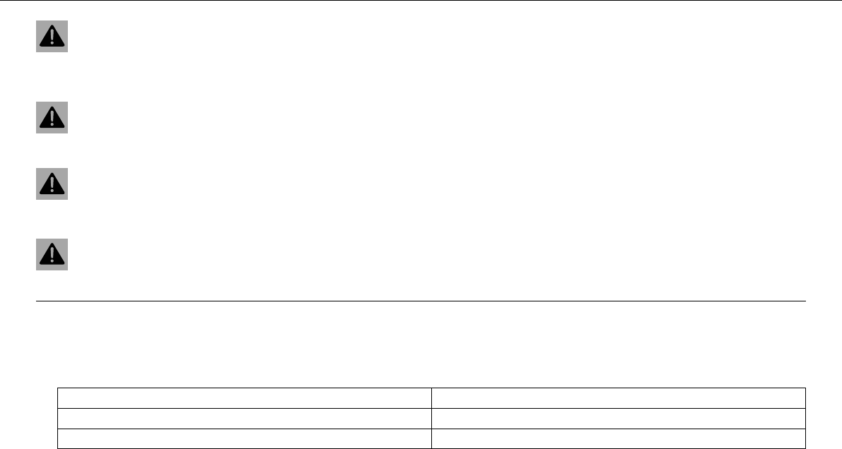
The symbols used are explained in the following.
Indicates an expected reaction (e.g. of a work step or a function).
Indicates an unexpected reaction (e.g. of a work step or a function).
All work marked with this symbol requires specialist knowledge and technical understanding. In the interest of your
own safety, have these jobs done in an authorized KTM workshop! There, your motorcycle will be serviced optimally
by specially trained experts using the specialist tools required.
Identifies a page reference (more information is provided on the specified page).
Formats used
The typographical and other formats used are explained in the following.
Eigenname Indicates a proprietary name.
Name®Identifies a protected name.
Marke™ Identifies a brand in merchandise traffic.
IMPORTANT NOTES 8
2IMPORTANT NOTES
Use definition
KTM sport motorcycles are designed and constructed to meet the normal demands of regular road and light offroad operation (dirt roads),
but not for use on race courses.
Info
The motorcycle is authorized for public road traffic in the homologous version only.
Maintenance
A prerequisite for perfect operation and prevention of wear is that the engine and chassis maintenance and adjustment work described in
the owner's manual are properly carried out. Poor adjustment and tuning of the engine and chassis can lead to damage and breakage of
components.
Using the motorcycle in extreme conditions such as very muddy or wet roads can lead to above-average wear of components such as the
transmission train or the brakes. For this reason, it may be necessary to service or replace worn parts before the limit specified in the
greasing and service table is reached.
Pay careful attention to the prescribed running-in period, inspection and maintenance intervals. If you observe these exactly, you will
ensure a much longer service life for your motorcycle.
Warranty
The maintenance work prescribed in the greasing and service table must be carried out in an authorized KTM workshop and confirmed in
the customer's service record, since otherwise no warranty claims will be recognized. No warranty claims can be considered for damage
resulting from manipulations and/or alterations to the vehicle.
Fuel, oils, etc.
You should use the fuels, oils and greases according to specifications as listed in the owner's manual.

IMPORTANT NOTES 9
Spare parts, accessories
For your own safety, use only spare parts and accessories approved by KTM, and have these mounted only in an authorized KTM workshop.
KTM accepts no liability for other products and any resulting damage or loss.
The currentKTMPowerParts for your vehicle can be found on the KTM website.
International KTM Website: http://www.ktm.com
Transport
Note
Danger of damage Danger of damage by the vehicle running away or falling over.
–Always place the vehicle on a firm and even surface.
Note
Fire hazard Some components (engine, radiator and exhaust system) get very hot when the engine is running.
–Do not place the vehicle where there are flammable or explosive substances.
–Switch off the engine and remove the ignition key.
–Use straps or other suitable devices to secure the motorcycle against accidents or falling over.
Environment
Offroad motorcycling is a wonderful sport and we naturally hope that you will be able to enjoy it to the fullest. However, it is a potential
problem for the environment and can lead to conflicts with other persons. But if you use your motorcycle responsibly, you can ensure that
such problems and conflicts do not have to occur. To protect the future of motorcycle sport, make sure that you use your motorcycle
legally, display environmental consciousness, and respect the rights of others.
IMPORTANT NOTES 10
Notes/warning notes
Pay attention to the specified notes and warnings.
Info
Various notes and warning labels are attached to the vehicle. Do not remove any notes or warning labels. If they are missing, you or
others may not recognize dangers and may therefore be injured.
Grades of risks
Danger
Danger that leads immediately and certainly to severe and permanent injury or death.
Warning
Danger that will probably lead to severe and permanent injury or death.
Caution
Danger that could possibly lead to slight injuries.
Note
Danger of serious damage to machine or material.
Warning
Risk of environmental damage.
OWNER'S MANUAL
–Read this owner's manual carefully and completely before making your first trip. It contains a lot of information and tips to help you
operate and handle your motorcycle. Only then will you find out how to customize the motorcycle ideally for your own use and how you
can protect yourself from injury. The owner's manual also contains important information on servicing the motorcycle.

IMPORTANT NOTES 11
–The owner's manual is an important component of the motorcycle and should be handed over to the new owner if the vehicle is sold.
VIEW OF VEHICLE 12
3VIEW OF VEHICLE
3.1
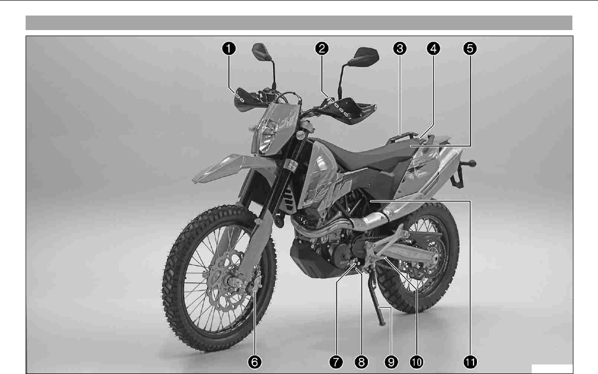
View of vehicle, front left side
100234-10

VIEW OF VEHICLE 13
1 Hand brake lever
2 Clutch lever
3 Handrail
4 Filler cap
5 Seat
6 Front brake caliper
7 Shift lever
8 Engine number
9 Side stand
10 Footrest
11 Seat release strap
VIEW OF VEHICLE 14
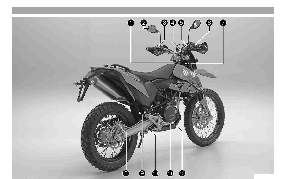
3.2View of vehicle, rear right side
100235-10

VIEW OF VEHICLE 15
1 Ignition/steering lock
2 Rear mirror
3 Light switch, flasher switch, horn
4 Combination instrument
5 Emergency OFF switch, electric starter button
6 Throttle grip
7 Chassis number
8 Rear brake caliper
9 Passenger footrest
10 Shock absorber rebound damping
11 Foot brake pedal
12 Engine oil level viewer
LOCATION OF SERIAL NUMBERS 16
4LOCATION OF SERIAL NU MBERS
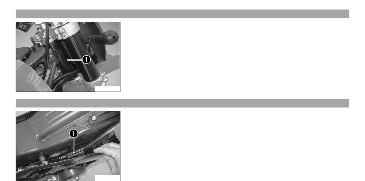
4.1
Chassis number
100217-10
The chassis numberis stamped on the steering head on the right.
4.2Type label
100218-10
Type labelis located on the upper right frame tube below the seat.
LOCATION OF SERIAL NUMBERS 17
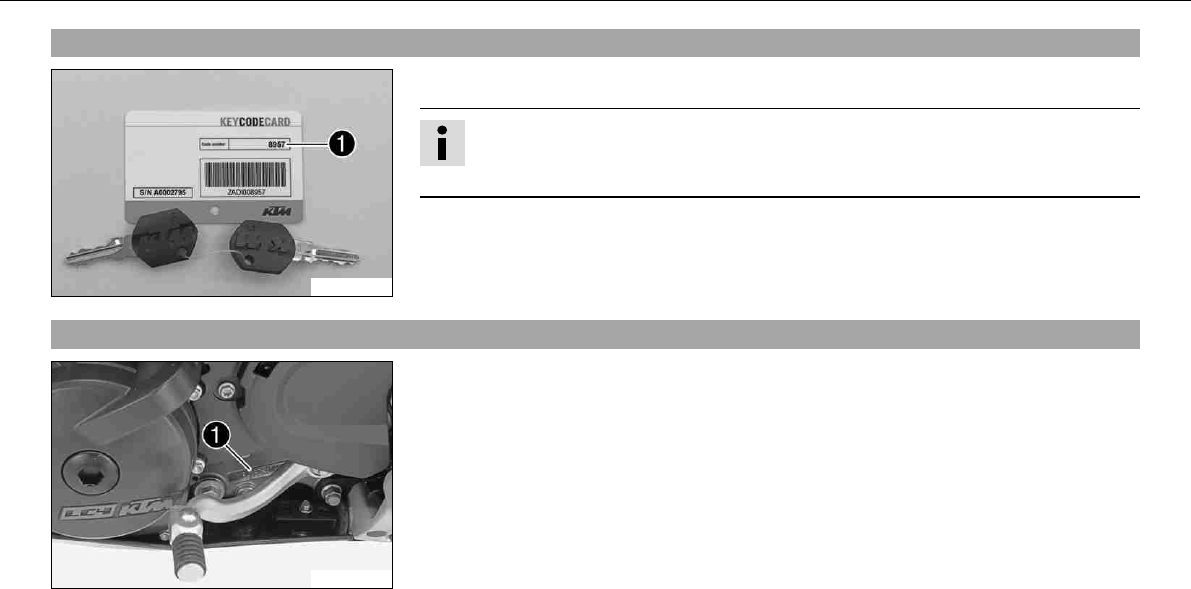
4.3Key number
100179-10
The key numbercan be found on theKEYCODECARD.
Info
You need the key number to order a spare key. Keep theKEYCODECARD in a safe
place.
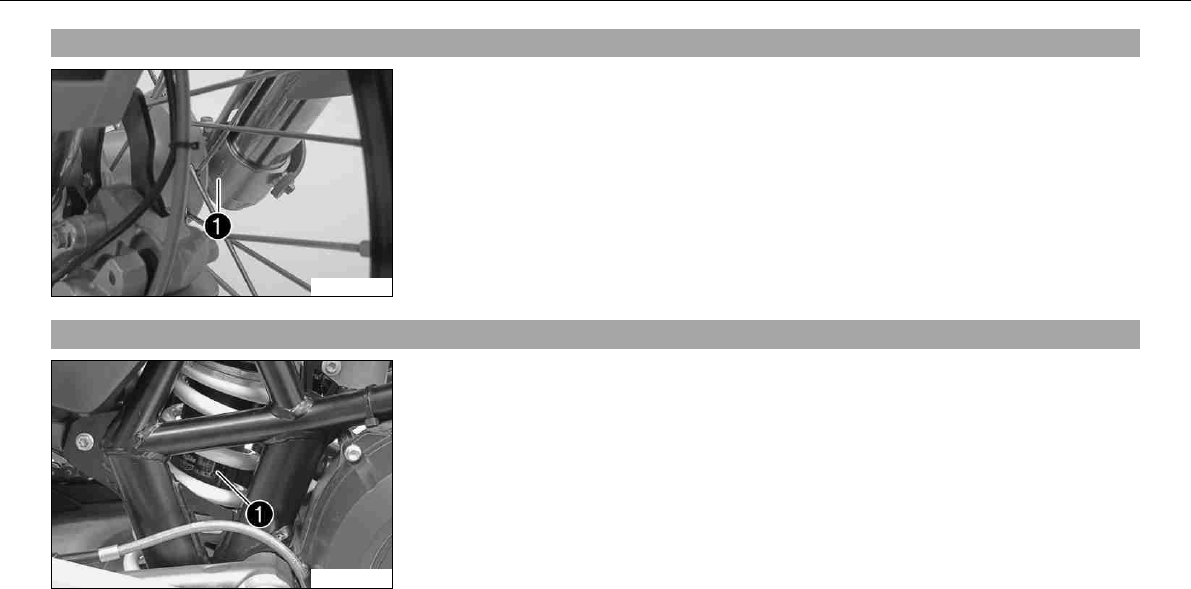
4.4Engine number
100211-10
The engine numberis stamped on the left side of the engine under the engine sprocket.
LOCATION OF SERIAL NUMBERS 18
4.5Fork part number
100214-10
The fork part numberis stamped on the inner side of the fork stub.
4.6Shock absorber part number
100216-10
Shock absorber part numbercan be viewed from the right side.
OPERATING ELEMENTS 19
5OPERATING ELEMENTS
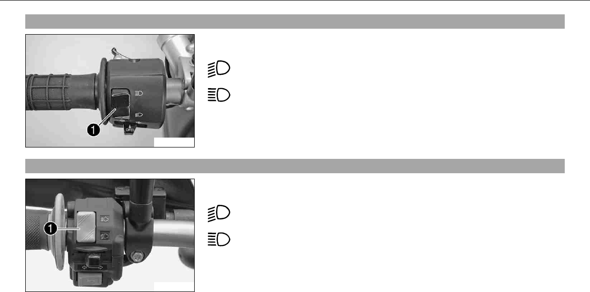
5.1Clutch lever
100219-10
The clutch leveris fitted on the left side of the handlebar.
The clutch is hydraulically operated and self-adjusting.
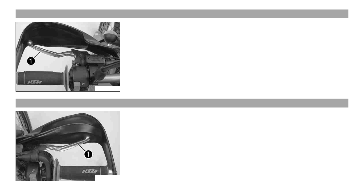
5.2Hand brake lever
100220-10
The hand break leveris fitted on the right side of the handlebar.
The hand brake lever operates the front brake.
OPERATING ELEMENTS 20
5.3Light switch
500020-01
The light switchis fitted on the left side of the handlebar.
Possible states
Low beam on –Light switch is turned downwards. In this position, the low
beam and tail light are switched on.
High beam on –Light switch is turned upwards. In this position, the high
beam and the tail light are switched on.
5.4Light switch
100222-10
The light switchis fitted on the left side of the handlebar.
Possible states
Low beam on –Light switch is turned downwards. In this position, the low
beam and tail light are switched on.
High beam on –Light switch is turned upwards. In this position, the high
beam and the tail light are switched on.
OPERATING ELEMENTS 21
5.5Headlight flasher switch
500020-11
The headlight flasher switchis fitted on the left side of the handlebar.
Possible states
• Headlight flasher switch in neutral position
• Headlight flasher switch pressed –In this position, the headlight flasher (high beam)
is actuated.
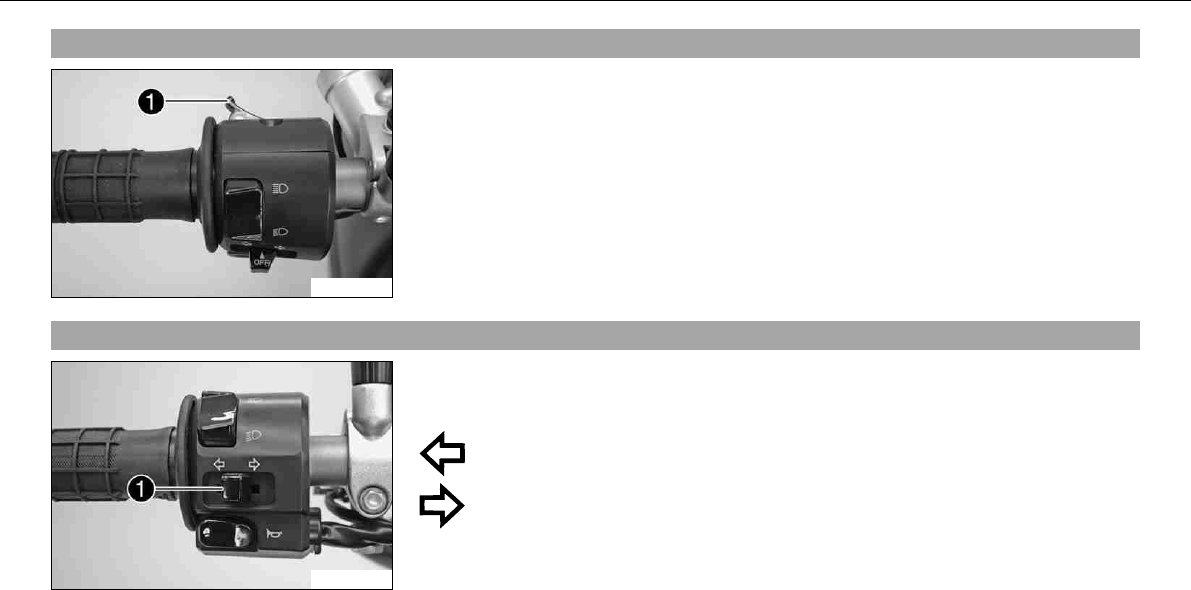
5.6Flasher switch
500021-10
The flasher switchis fitted on the left side of the handlebar.
Possible states
Flasher light off
Flasher light, left, on –Flasher switch pressed to the right. The flasher
switch returns automatically to the central position after use.
Flasher light, right, on –Flasher switch pressed to the right. The flasher
switch returns automatically to the central position after use.
To switch off the flasher light, press the flasher switch towards the switch case.
OPERATING ELEMENTS 22
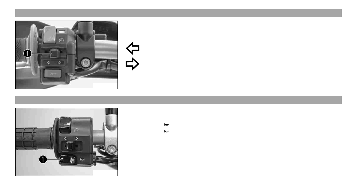
5.7Flasher switch
100223-10
The flasher switchis fitted on the left side of the handlebar.
Possible states
Flasher light off
Flasher light, left, on –Flasher switch pressed to the right. The flasher
switch returns automatically to the central position after use.
Flasher light, right, on –Flasher switch pressed to the right. The flasher
switch returns automatically to the central position after use.
To switch off the flasher light, press the flasher switch towards the switch case.
5.8Horn
500021-11
The horn buttonis fitted on the left side of the handlebar.
Possible states
• Horn buttonin neutral position
• Horn buttonpressed –The horn is operated in this position.
OPERATING ELEMENTS 23
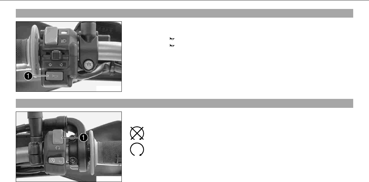
5.9Horn
100224-10
The horn buttonis fitted on the left side of the handlebar.
Possible states
• Horn buttonin neutral position
• Horn buttonpressed –The horn is operated in this position.
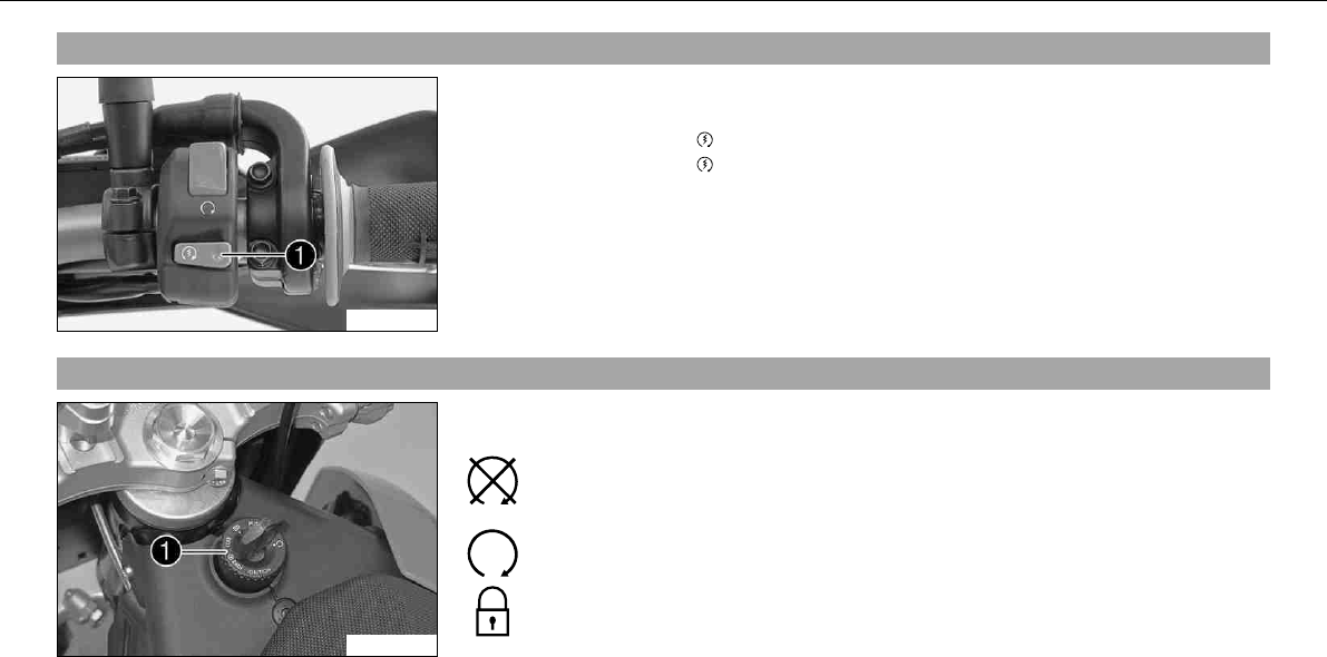
5.10Emergency OFF switch
100225-10
The emergency OFF switchis fitted on the left side of the handlebar.
Possible states
Emergency OFF switch off –In this position, the ignition circuit is inter-
rupted, a running engine stops, and the engine cannot be started.
Emergency OFF switch on –This position is necessary for operation as the
ignition circuit is closed.
OPERATING ELEMENTS 24
5.11Electric starter button
100226-10
The electric starter buttonis fitted on the right side of the handlebar.
Possible states
• Electric starter buttonin basic position
• Electric starter buttonpressed –In this position, the electric starter is actuated.
5.12Ignition/steering lock
100221-10
The ignition/steering lockis located in front of the seat.
Possible states
Ignition off –In this position, the ignition circuit is interrupted, a running
engine stops, and a non-running engine will not start. The ignition key can
be removed.
Ignition on –In this position, the ignition circuit is closed, and the engine
can be started.
Steering locked –In this position, the ignition circuit is interrupted and the
steering locked. The ignition key can be removed.
OPERATING ELEMENTS 25
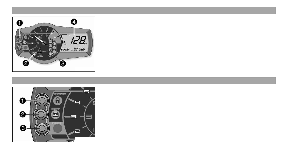
5.13Combination instrument
700116-01
The combination instrument is attached in fromt of the handlebar.
The combination instrument is divided into 4 function areas.
Function buttons
Tachometer
Indicator lights
Display
5.14Combination instrument - function buttons
700117-01
Press theMODEbuttonto change the display mode.
Possible display modes are total distance covered (ODO), tripmaster1(TRIP1) and tripmas-
ter2(TRIP2).
Press theSETbuttonto reset tripmaster1(TRIP1) and tripmaster2(TRIP2) to0.0.
Buttonhas no function.
OPERATING ELEMENTS 26
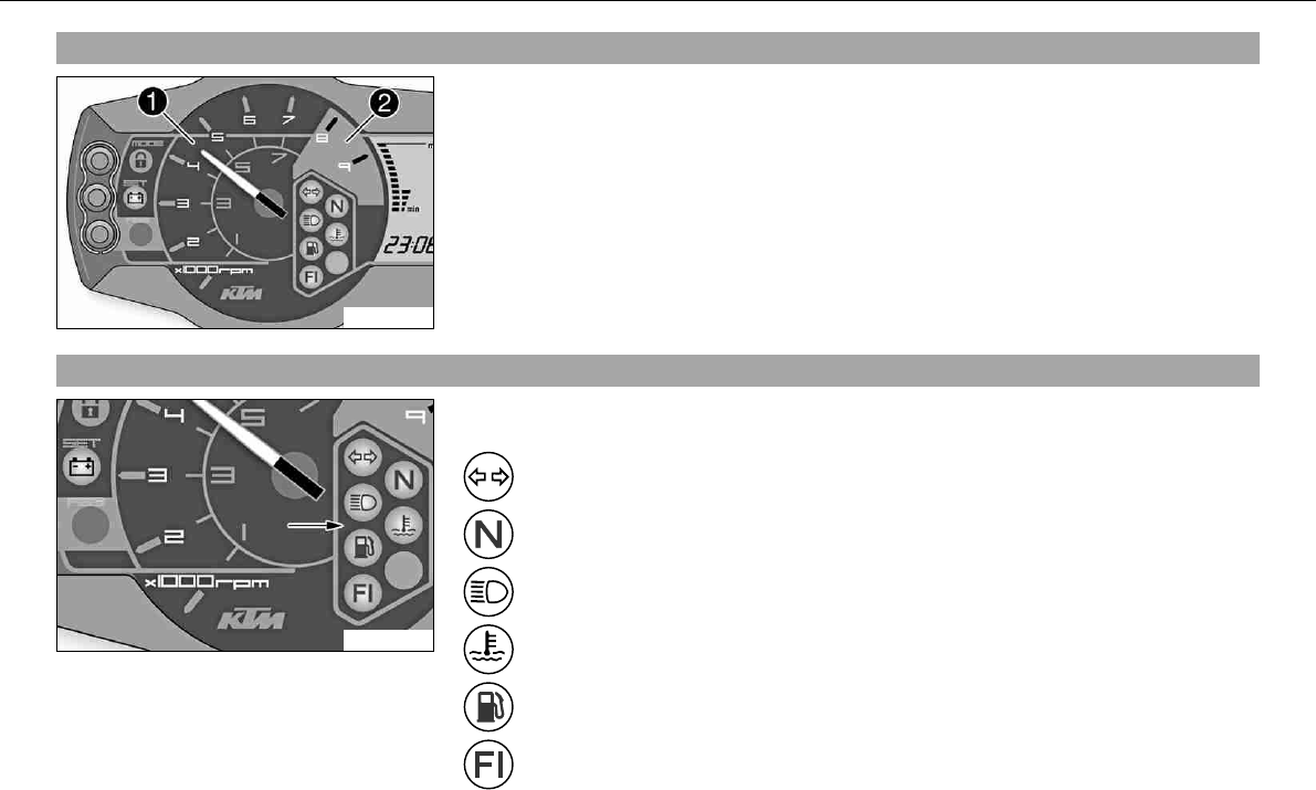
5.15Combination instrument - tachometer
100118-10
The tachometerdisplays the engine speed in revolutions per minute.
The red markingshows the excess engine speed range.
5.16Combination instrument - control lamps
100119-10
The indicator lamps provide additional information on the operating state of the motorcycle.
Possible states
Flashing indicator flashes green in flash rhythm –Flasher light is switched
on.
Idling speed indicator lamp lights up green –Transmission is in neutral.
High beam indicator lamp lights up blue –High beam is switched on.
Temperature warning lamp lights up red –Coolant has reached a critical
value.
Fuel level warning lamp lights up orange –Fuel level has reached the reserve
mark. Display switches toTRIPF.
FIwarning lamp(MIL) lights/flashes orange –The OBD has detected an
emission- or safety-critical error.
OPERATING ELEMENTS 27
Battery warning lamp lights up –Voltage in electrical system too low.
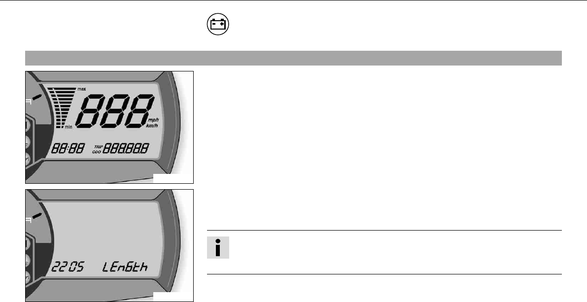
5.17Combination instrument - Display
700118-01
When you switch on the ignition, all display segments light up for a second as a function
test.
400404-01
LEnGTth
Following the display function test, the wheel circumferenceLEnGth is shown for one sec-
ond.
Info
2205 mm equals the circumference of the 21" front wheel with a series production
tire.
The display then changes to the last selected mode.
OPERATING ELEMENTS 28
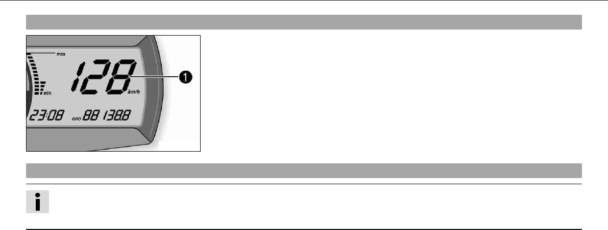
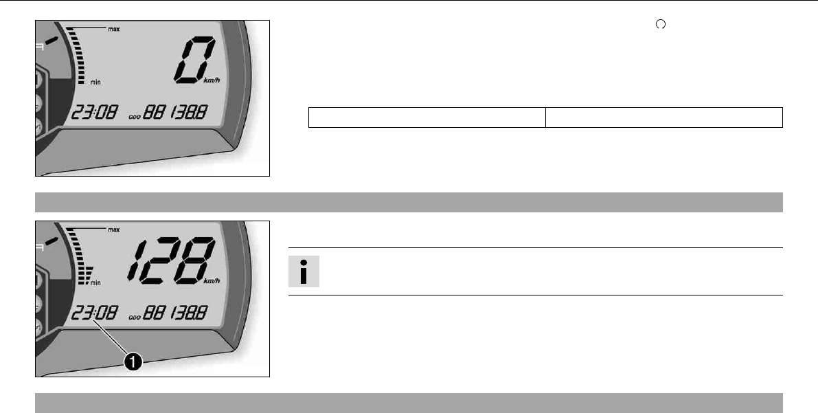
5.18Combination instrument - speed display
700114-01
The speedis displayed in kilometers per hourkm/h or miles per hourMph.
5.19Setting kilometers or miles
Info
If you change the unit, the ODO value is retained and converted accordingly.
Making the setting according to the country.
Condition
The motorcycle is standing.
OPERATING ELEMENTS 29
700120-01
–Switch on the ignition by turning the ignition key in the position.
–Press theMODEbutton several times until theODO display mode is active.
–Keep the MODEbutton pressed until the display mode changes fromKm/h to Mph or
from Mph to Km/h.
Specification
Activation duration of MODEbutton 10s
5.20Combination instrument - time
700115-01
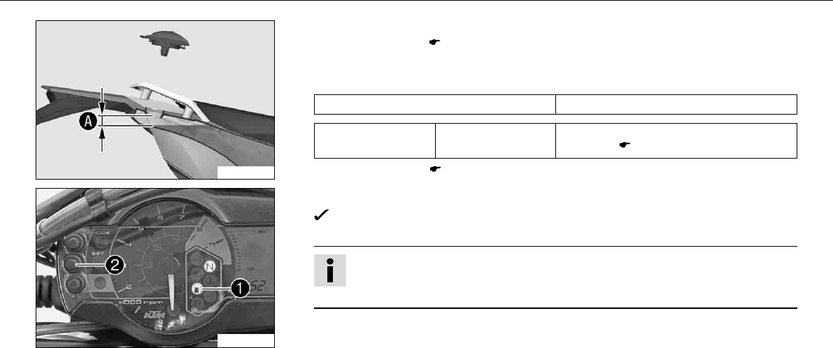
The time is shown in areaof the display.
Info
The time must be adjusted after the battery is disconnected or the fuse is changed.
5.21Setting the clock
Condition
The motorcycle is standing.
OPERATING ELEMENTS 30
700115-10
–Switch on the ignition by turning the ignition key in the position.
–Press theMODEbutton several times until theODO display mode is active.
–Keep theMODEbutton and theSETbutton pressed simultaneously.
The time begins to flash.
–Press theMODEbutton to adjust the hour.
–Press theSETbutton to adjust the minute.
–Keep theMODEbutton and theSETbutton pressed simultaneously.
The time is set.
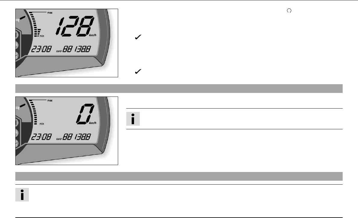
5.22Combination instrument -ODO display
700120-01
InODO mode, the total distance covered is shown in kilometers or miles.
Info
This value remains intact even if the battery is disconnected and/or the fuse blows.
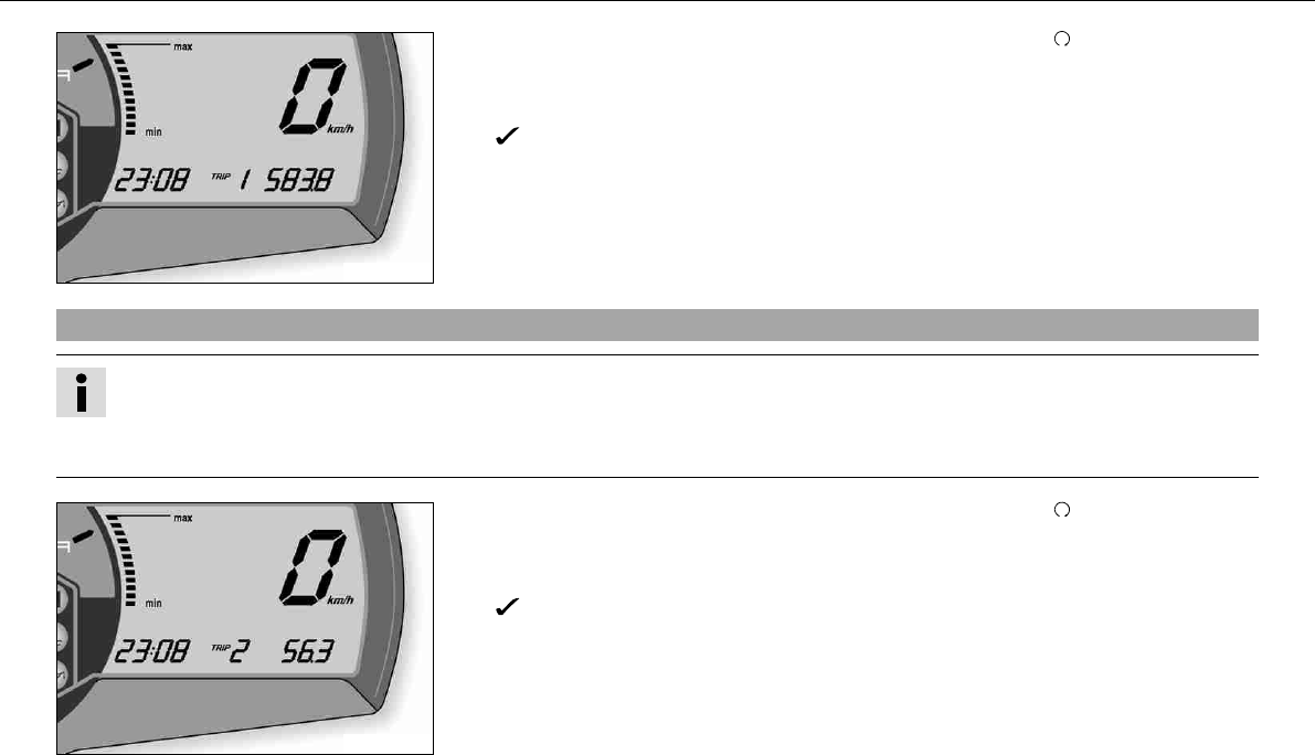
5.23Combination instrument - setting/resettingTRIP1 display
Info
The tripmasterTRIP1operates constantly and counts up to999.9.
You can use the tripmaster to measure trips or the distance between refuelling stops. After reaching 999.9, the tripmaster begins
again at 0.0.
OPERATING ELEMENTS 31
700121-01
–Switch on the ignition by turning the ignition key in the position.
–Press theMODEbutton several times until theTRIP1display mode is active.
–Keep theSETbutton pressed.
TheTRIP1display is at0.0.
5.24Combination instrument - setting/resettingTRIP2 display
Info
The tripmasterTRIP2operates constantly and counts up to999.9.
You can use the tripmaster to measure trips or the distance between refuelling stops. After reaching 999.9, the tripmaster begins
again at 0.0.
700122-01
–Switch on the ignition by turning the ignition key in the position.
–Press theMODEbutton several times until theTRIP2display mode is active.
–Keep theSETbutton pressed.
TheTRIP2display is at0.0.
OPERATING ELEMENTS 32
5.25Combination instrument -TRIPF display
700123-01
When the fuel level reaches the reserve mark, the display automatically changes toTRIPF
and begins to count from0.0, regardless of which display mode was previously active.
Info
Parallel to theTRIPFdisplay, the fuel warning light begins to light up.
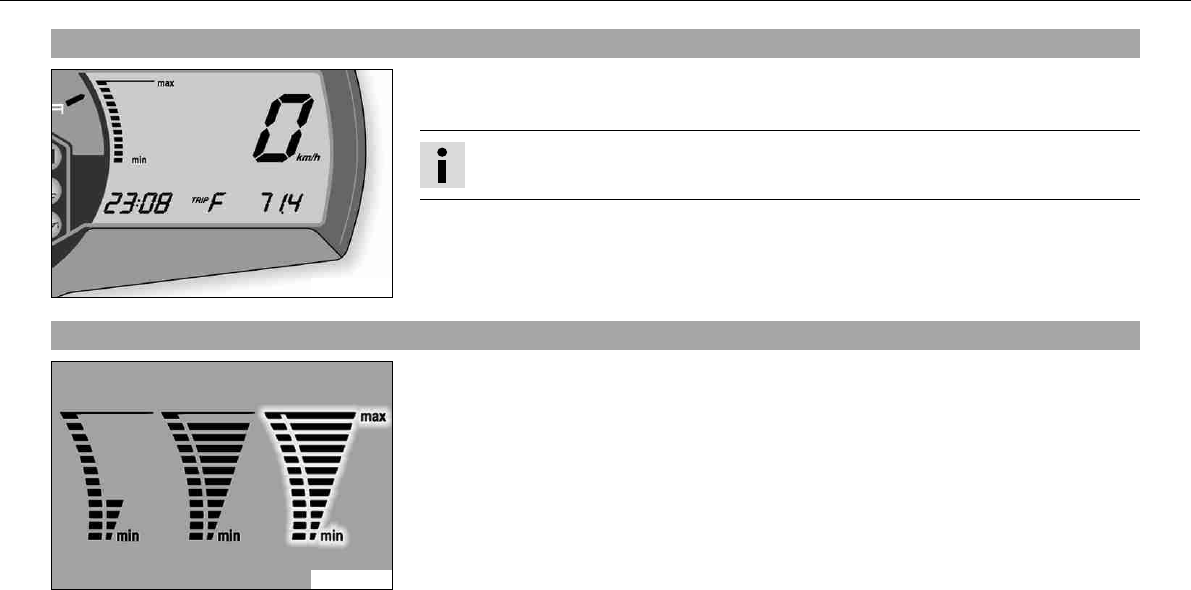
5.26Combination instrument - coolant temperature indicator
700124-01
The temperature indicator in the display consists of 12 bars. The more bars that light up,
the hotter the coolant. When the top bar lights up, all bars begin to flash simultaneously
and the temperature warning lamp begins to light up.
Possible states
• Engine cold –up to four bars light up.
• Engine at normal operating temperature –from five to eleven bars light up.
• Engine hot –all twelve bars flash.
OPERATING ELEMENTS 33
5.27Opening filler cap
100227-10
–Lift the cover of the filler capand insert the ignition key.
–Turn the ignition key 90° counterclockwise and remove the filler cap.
Info
The filler cap has a tank air vent system.
5.28Closing filler cap
100228-01
–Put the filler cap back on and turn the ignition key 90° clockwise.
–Remove the ignition key and fold down the cover.
OPERATING ELEMENTS 34
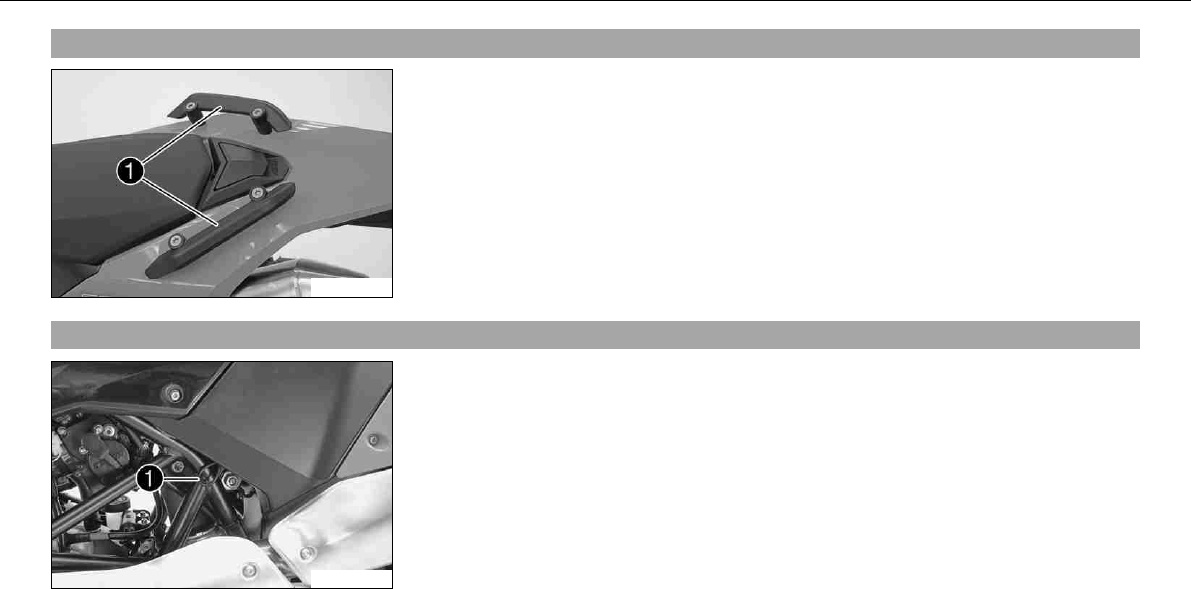
5.29Handrails
100229-10
The handrailsare used for moving the motorcycle around.
When you have a passenger, the passenger can hold on the handrails during the journey.
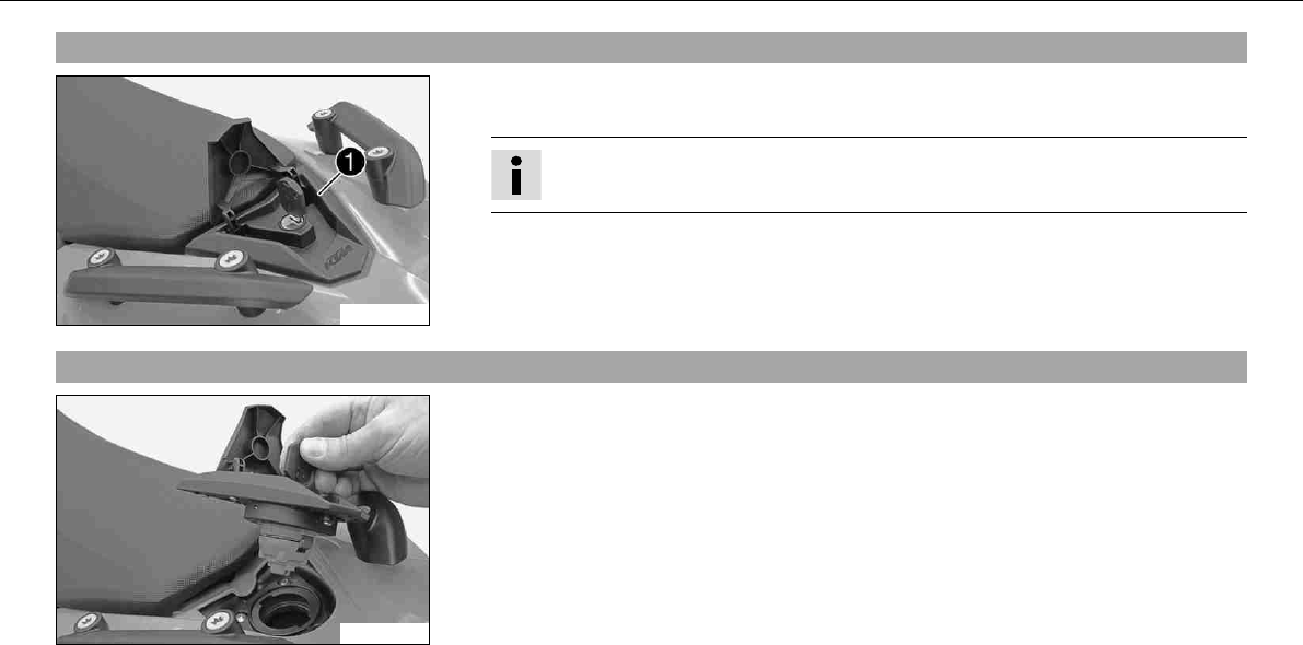
5.30Seat release
100230-10
The seat can be released using strap.
OPERATING ELEMENTS 35
5.31Passenger footrests
100231-01
The passenger footrestscan be folded up and down.
Possible states
• Passenger footrests folded up –For operation without a passenger.
• Passenger footrests folded down –For operation with a passenger.
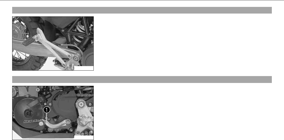
5.32Shift lever
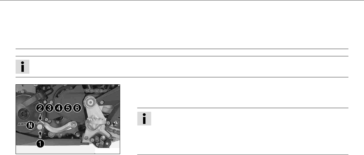
100215-10
The shift leveris mounted on the left side of the engine.
OPERATING ELEMENTS 36
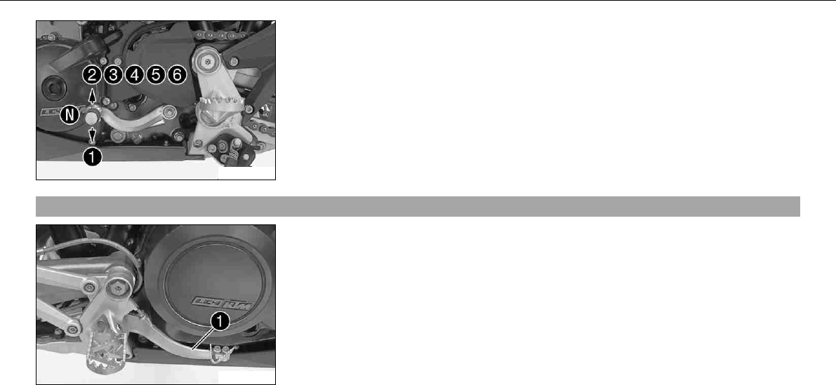
100212-10
The gear positions can be seen in the photograph.
The neutral or idle position is between the first and second gears.
5.33Foot brake pedal
100232-10
The footbrake pedalis located in front of the right footrest.
The footbrake pedal operates the rear brake.
OPERATING ELEMENTS 37
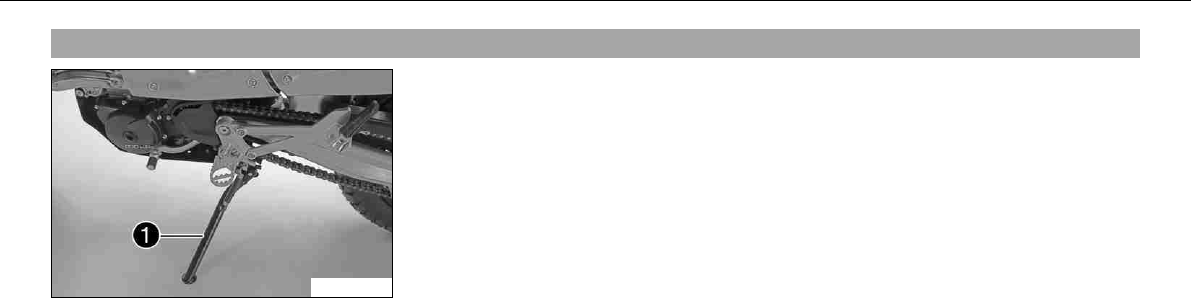
5.34Side stand
100233-10
The side standis coupled with the safety electric starter system - see the riding instruc-
tions.
Possible states
• Side stand folded out –The vehicle can be supported on the side stand. The safety
electric starter system is active.
• Side stand folded in –This position is mandatory for all journeys. The safety electric
starter system is inactive.
GENERAL TIPS AND HINTS ON PUTTING INTO OPERATION 38
6GENERAL TIPS AND HINTS ON PUTTING INT O OPERATION
6.1
Advice on first use
Danger
Danger of accidents Danger from inadequate traffic experience.
–Do not use the vehicle if you are inexperienced or if you have consumed alcohol or drugs.
Warning
Risk of injury Risk of injury by missing/inadequate protective clothing.
–Wear protective clothing (helmet, boots, gloves, pants and jacket with protectors) every time you ride the motorcycle. Always
wear protective clothing, which must be in perfect condition and meet legal requirements.
Warning
Danger of crashing Impairment of riding behavior due to different tire tread patterns on front and rear wheels.
–The front and rear wheels must be fitted with tires with similar tread patterns to prevent loss of control over the vehicle.
Warning
Danger of accidents Uncontrollable handling behavior caused by non-approved tires/wheels.
–Use only tires/wheels approved by KTM with the corresponding speed index.
Warning
Danger of accidents Reduced road grip with new tires.
–New tires have a smooth roll surface and therefore cannot provide full road grip. The entire roll surface must be roughened in
the first 200 kilometers (124.3 miles) by moderate driving at alternating angles. The full grip is not reached until the vehicle
has been run in.
Warning
Danger of accidents Brake system failure.
–If the foot brake pedal is not released, the brake linings drag permanently. The rear brake can fail due to overheating. Take your
foot off the foot brake pedal if you do not want to brake.
GENERAL TIPS AND HINTS ON PUTTING INTO OPERATION 39
Info
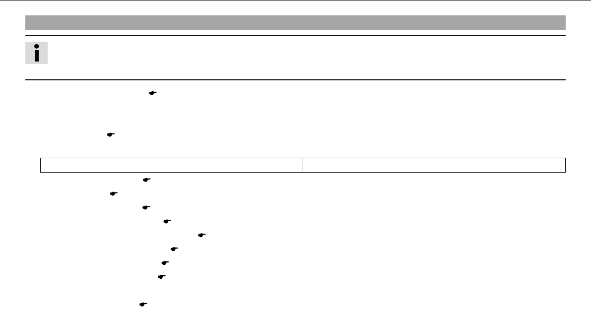
When using your vehicle, remember that others may feel disturbed by excessive noise.
–Make sure that the pre-delivery inspection work has been carried out by an authorized KTM workshop.
You receive a delivery certificate and the service record at vehicle handover.
–Before your first trip, read the entire operating instructions carefully.
–Get to know the operating elements.
–adjust the basic position of clutch lever. ( P. 129)
–Adjust the free travel of the handbrake lever. ( P. 77)
–Adjust the basic position of the foot brake pedal.x( P. 85)
–Get used to handling the vehicle on a car park before making a longer trip. Try also to ride as slowly as possible and in a standing posi-
tion to get a better feeling for the vehicle.
–Do not make any offroad trips that over-stress your ability and experience.
–Hold the handlebar firmly with both hands and keep your feet on the footrests when riding.
–Do not make any changes to the vehicle, and use only KTM approved parts.
Info
Parts from other manufacturers can reduce the operational safety of the vehicle.
–Run the engine in.
GENERAL TIPS AND HINTS ON PUTTING INTO OPERATION 40
6.2Running in the engine
–During the running-in phase, do not exceed the specified engine speed and engine performance.
Specification
Maximum engine speed
During the first: 1,000km (621.4mi) 6,000rpm
After the first: 1,000km (621.4mi) 7,800rpm
–Avoid fully opening the throttle!
6.3Loading the vehicle
Warning
Danger of accidents Unstable riding behavior.
–Do not exceed the maximum permitted weight and axle loads. The overall weight consists of: motorcycle operational and with a
full tank, driver and passenger with protective clothing and helmet, baggage.
Warning
Danger of accidents Unstable handling characteristics due to incorrect mounting of suitcase and/or tank rucksack.
–Mount and secure suitcase and tank rucksack according to the manufacturer's instructions.
Warning
Danger of accidents Unstable handling characteristics at high speed.
–Adapt your speed according to your payload. Ride more slowly if your motorcycle is loaded with cases or other baggage.
Maximum speed with baggage 130km/h (80.8mph)
Warning
Danger of accidents Risk of breakage of suitcase system.
–If you have fitted suitcases on your motorcycle, read the manufacturer's specifications concerning the maximum payload.
GENERAL TIPS AND HINTS ON PUTTING INTO OPERATION 41
Warning
Danger of accidents Poor visibility for other road users due to slipped baggage.
–If the tail light is covered, you are less visible to following traffic, especially in the dark. Check the way your baggage is fixed
regularly.
Warning
Danger of accidents Changed handling characteristics and longer stopping distance with excessive payload.
–Adapt your speed according to your payload.
Warning
Danger of accidents Unstable handling characteristics due to slipped baggage.
–Check the way your baggage is fixed regularly.
Warning
Danger of burns A hot exhaust system can burn baggage.
–Fasten your baggage in such a way that it cannot be burned or singed by the hot exhaust system.
–If you carry any baggage, make sure it is fixed firmly as close as possible to the center of the vehicle and ensure even weight distribu-
tion between the front and rear wheels.
–Do not exceed the overall maximum permitted weight and the axle loads.
Specification
Maximum permissible overall weight 350kg (772lb.)
Maximum permissible front axle load 150kg (331lb.)
Maximum permissible rear axle load 200kg (441lb.)
RIDING INSTRUCTIONS 42
7RIDING INSTRUCTIONS
7.1
Checks before putting into operation
Info
Make sure that the motorcycle is in a perfect technical condition before use.
In the interests of riding safety, make a habit of making a general check before you ride.
–Check the engine oil level. ( P. 133)
–Check the engine for loss of oil.
–Check the fuel level.
–Bleed fork legs. ( P. 62)
Specification
all 1,000km (621.4mi)
–Check the chain tension. ( P. 70)
–Clean the chain. ( P. 69)
–Check the tire condition. ( P. 98)
–Checking the tire air pressure. ( P. 100)
–Check the front brake brake fluid level. ( P. 78)
–Check the rear brake fluid level. ( P. 86)
–Check the front brake linings. ( P. 81)
–Check the rear brake linings. ( P. 89)
–Check brake system function.
–Check the coolant level. ( P. 124)
–Check that all operating elements are correctly adjusted and free to move.
–Check the functioning of the electrical equipment.
–Check that baggage is correctly secured.
–Sit on the motorcycle and check the rear mirror setting.
RIDING INSTRUCTIONS 43
7.2Starting
Danger
Danger of poisoning Exhaust gases are poisonous and can result in unconsciousness and/or death.
–When running the engine, always make sure there is sufficient ventilation, and do not start or run the engine in a closed space.
Caution
Danger of accidents If the vehicle is operated with a discharged battery or without a battery, electronic components and safety
equipment may be damaged.
–Never operate the vehicle with a discharged battery or without a battery.
Note
Engine failure High engine speeds in cold engines have a negative effect on the service life of the engine.
–Always warm up the engine at low engine speeds.
RIDING INSTRUCTIONS 44
100239-10
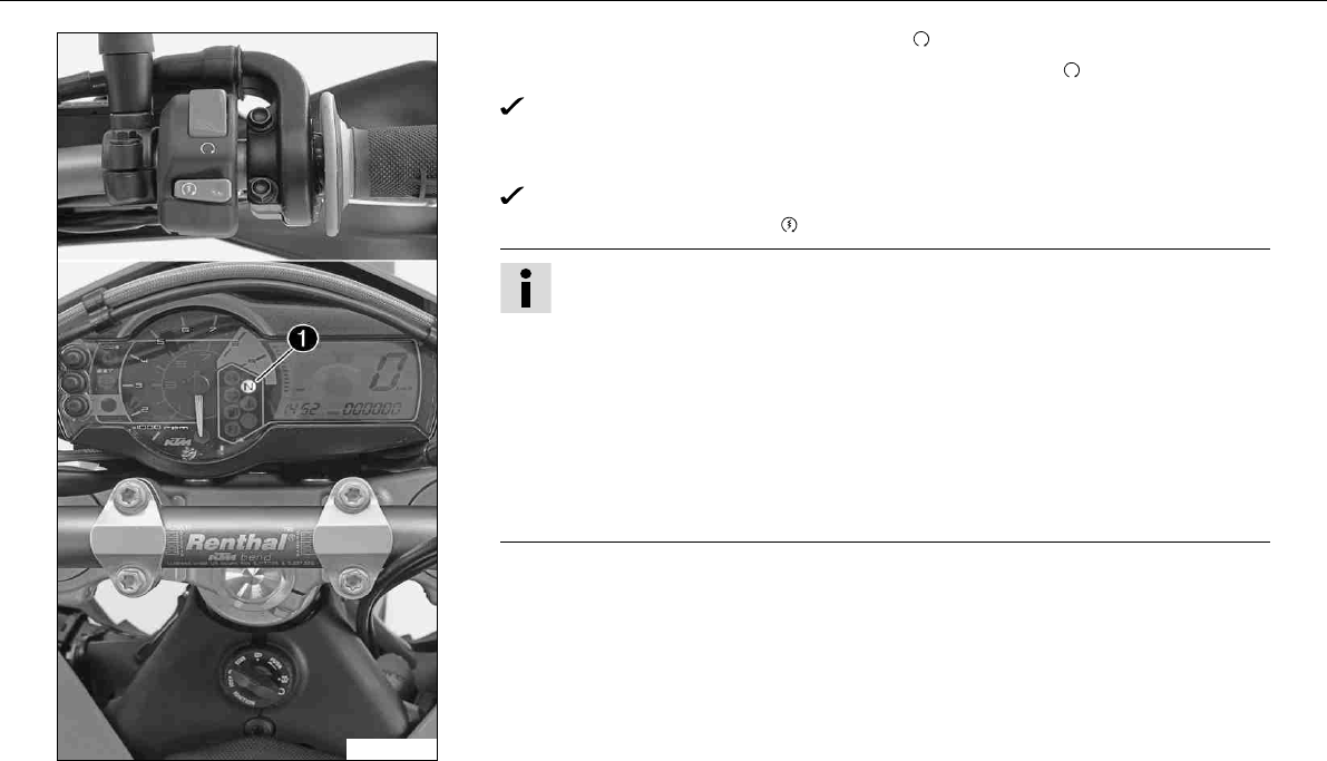
–Turn the emergency OFF switch to theposition.
–Switch on the ignition by turning the ignition key in the position.
After switching on the ignition, you can hear the fuel pump working for about 2
seconds. At the same time, the combination instrument runs a function test.
–Shift gear to neutral.
The green idling speed indicator lampNlights up.
–Press the electric starter button.
Info
Do not press the electric starter button until the combination instrument func-
tion test is finished.
Do not open the throttle when starting. If you open the throttle when starting,
the engine management injects no fuel and the engine cannot start.
Press the starter for a maximum of 5 seconds. Wait for at least 5 seconds until
trying again.
This motorcycle is equipped with a safety electric starter system. The engine
can be started only if the gearbox is in neutral or the clutch lever is pulled. If
you shift into gear when the side stand is folded out and then release the clutch
lever, the engine stalls.
–Take the weight off the side stand and swing it back up with your foot as far as it will
go.
RIDING INSTRUCTIONS 45
7.3Starting up
–Pull the clutch lever, engage 1st gear, release the clutch lever slowly and simultaneously open the throttle carefully.
7.4Shifting, riding
Warning
Danger of accidents An abrupt load alterations can cause the vehicle to get out of control.
–Avoid abrupt load alterations and sudden braking actions, and adapt your speed to the road conditions.
Warning
Danger of accidents If you change down at high engine speed, the rear wheel can lock up.
–Do not change into a low gear at high engine speed. The engine races and the rear wheel can block.
Warning
Danger of accidents Malfunctions caused by incorrect ignition key position.
–Do not change the ignition key position during a journey.
Warning
Danger of accidents Distraction from traffic activity by adjustments to the vehicle.
–Make all adjustments when the vehicle is at a standstill.
Warning
Risk of injury The passenger must be capable of sitting correctly on the passenger seat.
–The passenger must hold on to the rider or the handrails and place his feet on the passenger footrests. Note the regulations
governing the minimum age of passengers in your country.
Warning
Danger of accidents Danger of accidents caused by dangerous driving.
–Observe the traffic regulations and ride defensively and with foresight in order to recognize danger as early as possible.

RIDING INSTRUCTIONS 46
Warning
Danger of accidents Reduced road grip with cold tires.
–On every journey, take the first miles carefully at moderate speed until the tires reach operating temperature and optimal road
grip is ensured.
Warning
Danger of accidents Reduced road grip with new tires.
–New tires have a smooth roll surface and therefore cannot provide full road grip. The entire roll surface must be roughened in
the first 200 kilometers (124.3 miles) by moderate driving at alternating angles. The full grip is not reached until the vehicle
has been run in.
Warning
Danger of accidents Unstable riding behavior.
–Do not exceed the maximum permitted weight and axle loads. The overall weight consists of: motorcycle operational and with a
full tank, driver and passenger with protective clothing and helmet, baggage.
Warning
Danger of accidents Unstable handling characteristics due to slipped baggage.
–Check the way your baggage is fixed regularly.
Warning
Danger of accidents After a fall, check the vehicle.
–After a fall, check the vehicle as usual before putting it into operation.
Note
Engine failure Unfiltered intake air has a negative effect on the service life of the engine.
–Never ride the vehicle without an air filter since dust and dirt can get into the engine and result in increased wear.
RIDING INSTRUCTIONS 47
Note
Engine failure Overheating of engine.
–If the coolant temperature warning lamp lights up, stop and switch off the engine. Allow the engine to cool down and check the
coolant level in the radiator, and top up if necessary. If you continue with the coolant temperature warning lamp alight, you may have
engine failure.
Info
If you hear unusual noises while riding, stop immediately, switch off the engine and contact an authorized KTM workshop.
100212-10
–When conditions allow (incline, road situation, etc.), you can shift into a higher gear.
–Release the throttle while simultaneously pulling the clutch lever, shift into the next
gear, release the clutch and open the throttle.
Info
For the positions of the 6 forward gears, see the illustration. The neutral or idle
position is between the first and second gears. First gear is used for starting off
or for steep inclines.
The operating temperature is reached when 5 bars of the temperature indicator
light up.
–When you reach maximum speed after fully opening the throttle, turn back the throttle
to about ¾ of its range; the speed hardly drops, but the fuel consumption falls consid-
erably.
–Open the throttle only as far as the road and weather conditions permit. Particularly in
bends, do not shift and open the throttle only very cautiously.
–To shift down, brake if necessary and close the throttle at the same time.
–Pull the clutch lever and shift into a lower gear, release the clutch lever slowly and open
the throttle or shift again.
RIDING INSTRUCTIONS 48
–For example, if the engine stalls at a junction, just pull the clutch and press the electric
starter button. You do not need to shift into neutral.
–Switch off the engine if you expect to be standing for a long time.
–Avoid frequent and longer slipping of the clutch. This heats the engine oil, the engine
and the cooling system.
–Ride with a lower engine speed instead of with a high engine speed and a slipping
clutch.
–If the FIwarning lamp(MIL) starts to light up during the journey, stop immediately. If
you shift to neutral, theFIwarning lamp(MIL) begins to flash.
Info
From the flash rhythm, you can deduce a two-digit number, the so-called flash
code. The flash code tells you which component is affected by a fault.
7.5Braking
Warning
Danger of accidents If you brake too hard, the wheels can lock.
–Adapt your braking to the traffic situation and the road conditions.
Warning
Danger of accidents Reduced braking due to wet or dirty brakes.
–Clean or dry dirty or wet brakes by riding and braking gently.
Warning
Danger of accidents Reduced braking caused by spongy pressure point of front or rear brake.
–Have the brake system checked in an authorized KTM workshop, and do not ride any further.
RIDING INSTRUCTIONS 49
Warning
Danger of accidents Brake system failure.
–If the foot brake pedal is not released, the brake linings drag permanently. The rear brake can fail due to overheating. Take your
foot off the foot brake pedal if you do not want to brake.
Warning
Danger of accidents Longer stopping distance due to higher overall weight.
–Take the longer stopping distance into account when carrying a passenger and baggage.
Warning
Danger of accidents Delayed brake action on salted roads.
–Salt can be deposited on the brake discs. To achieve the normal braking effect, the brake discs must first be cleaned by brak-
ing.
–To brake, release the throttle and operate the front and rear brakes simultaneously.
–On sandy, wet or slippery surfaces, use the rear brake.
–Braking should always be completed before you go into a bend. Change down to a lower gear appropriate to your road speed.
–On long downhill stretches, use the braking effect of the engine. Change down one or two gears, but do not overstress the engine. In
this way, you have to brake far less and the brakes do not overheat.
7.6Stopping, parking
Warning
Risk of misappropriation Usage by unauthorized persons.
–Never leave the vehicle while the engine is running. Secure the vehicle against use by unauthorized persons. If you leave the
vehicle, lock the steering and remove the ignition key.
RIDING INSTRUCTIONS 50
Warning
Danger of burns Some vehicle components get very hot when the machine is driven.
–Do not touch hot components such as exhaust system, radiator, engine, shock absorber and brakes. Allow these components to
cool down before starting work on them.
Note
Danger of damage Danger of damage by the vehicle running away or falling over.
–Always place the vehicle on a firm and even surface.
Note
Fire hazard Some components (engine, radiator and exhaust system) get very hot when the engine is running.
–Do not place the vehicle where there are flammable or explosive substances.
Note
Material damage Damage and destruction of components by excessive load.
–The side stand is designed for the weight of the motorcycle only. Do not sit on the motorcycle when it is supported by the side stand
only. The side stand and/or the frame could be damaged and the motorcycle could fall over.
–Brake the motorcycle.
–Shift gear to neutral.
–Switch off the ignition by turning the ignition key in the position.
Info
If the engine is switched off with the emergency OFF switch and the ignition remains switched on at the ignition lock, power
continues to flow to most power consumers and the battery will discharge. You should therefore always switch off the engine
with the ignition key - the emergency OFF switch is intended for emergencies only.
–Park the motorcycle on a hard surface.
–Swing the side stand forward with your foot as far as it will go and lean the vehicle on it.
RIDING INSTRUCTIONS 51
–Lock the steering by moving the handlebar to the left, pressing down the ignition key in the positionand turning it to the position.
To make locking the steering easier, move the handlebar a little to the left and right. Remove the ignition key.
7.7Refueling
Danger
Fire hazard Fuel can easily catch fire.
–Never fill up the vehicle near open flames or burning cigarettes, and always switch off the engine first. Be careful that no fuel is
spilt, especially on hot vehicle components. Clean up spilt fuel immediately.
–Fuel in the fuel tank expands when warm and can escape if the tank is overfilled. See specifications on filling up with fuel.
Warning
Danger of poisoning Fuel is poisonous and a health hazard.
–Avoid contact between fuel and skin, eyes and clothing. Do not inhale fuel vapors. If fuel gets into your eyes, rinse immediately
with water and contact a doctor. Wash affected skin areas immediately with soap and water. If fuel is swallowed, contact a doc-
tor immediately. Change clothing that has come into contact with fuel.
Warning
Environmental hazard Improper handling of fuel is a danger to the environment.
–Do not allow fuel to get into the ground water, the ground, or the sewage system.
Info
This motorcycle is equipped with a regulated catalyst. Leaded fuel will destroy the catalyst. You should therefore use unleaded fuel
only.
RIDING INSTRUCTIONS 52
400405-10
–switch off engine.
–Open the filler cap. ( P. 33)
–Fill the fuel tank with fuel up to measurement.
Specification
Measurement of20mm (0.79in)
Fuel tank content 12l (3.2USgal) Super unleaded (ROZ 95 / RON 95 /
PON 91) ( P. 168)
–Close the filler cap. ( P. 33)
100240-10
–Press theSETfunction button for 2 seconds.
The fuel level warning lampswitches off. TRIPFis set to 0 and appears in the
previous display mode.
Info
If you do not press theSETfunction button, the reset takes place automati-
cally after about 3 minutes.
GREASING AND SERVICE TABLE 53
8GREASING AND SERVICE TA BLE
8.1
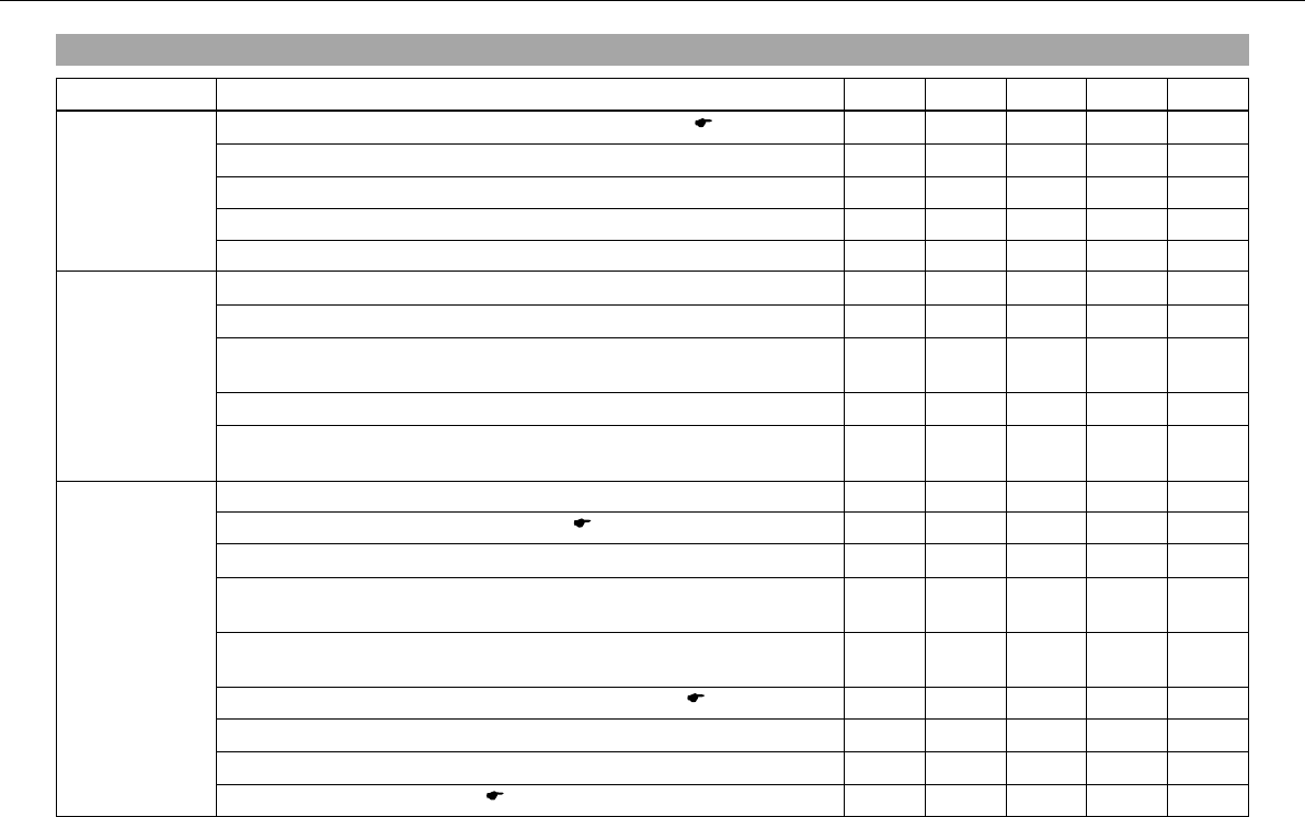
Important maintenance work to be carried out by an authorized KTM workshop.
K10N K50A K100A J1A J2A
Engine Change engine oil and oil filter, clean oil screens.x( P. 133) •••••
Check and adjust valve clearance.x• •
Check engine mounting screws for tightness. • • • • •
Replace spark plug. •
Check engine bolts accessible from outside for tightness. • • • • •
Fuel injection Check connection boots for cracks and leakage.x• • •
Read out the error memory with a KTM diagnostic tool.x•••••
Check fuel hoses, SLS hoses and vent hoses for damage, correct fit-
ting and leaks.x•••••
Clean, check and grease the O-ring of the fuel hose connection.x• • • •
Check the cable harness of the throttle valve body for damage and cor-
rect positioning.x• • •
Attachments Check the cooling system for leakage. • • • • •
Check the antifreeze and coolant level. ( P. 122) • • • • •
Check the functioning of the radiator fan.x•••••
Check the exhaust system for leaks and correct fitting and check that
the exhaust holders are tight.x•••••
Check Bowden cables for damage, smooth operation, routing without
sharp bends and setting. •••••
Check/correct the fluid level of the hydraulic clutch. ( P. 129) • • • •
Check air filter and change if necessary. Clean the air filter box.x• • • •
Check cables for damage and routing without sharp bends.x•••••
Check the headlamp setting. ( P. 118) • • • • •
GREASING AND SERVICE TABLE 54
K10N K50A K100A J1A J2A
Attachments Check the functioning of the electrical equipment. • • • • •
Check screws and nuts for tightness. • • • • •
Brakes Check the front brake linings. ( P. 81) • • • • •
Check the rear brake linings. ( P. 89) • • • • •
Check the brake discs. ( P. 75) • • • • •
Check the front brake brake fluid level. ( P. 78) • • • • •
Check the rear brake fluid level. ( P. 86) • • • • •
Change brake fluid.x•
Check brake lines for damage and leakage. • • • • •
Check the free play of the foot brake lever. ( P. 85) • • • • •
Check braking. • • • • •
Check screws and guide bolts of brake system for tightness.x•••••
Chassis Check shock absorber and fork for leakage and functioning.x•••••
Clean dust boots of fork legs.x• • • •
Bleed fork legs. ( P. 62) • • • • •
Check swingarm bearing.x•••••
Check play of steering head bearing.x( P. 65) •••••
Check all screws to see if they are tight. • • • • •
Grease Pro‑Lever deflector.x•
Wheels Check the spoke tension. ( P. 101) • • • • •
Check rim run-out.x•••••
Check the tire condition. ( P. 98) • • • • •
Checking the tire air pressure. ( P. 100) • • • • •
GREASING AND SERVICE TABLE 55
K10N K50A K100A J1A J2A
Wheels Check the chain wear. ( P. 74) • • • • •
Check rear sprocket / engine sprocket for tightness. • • • • •
Check rear sprocket / engine sprocket for wear. ( P. 73) • • • • •
Check the chain tension. ( P. 70) • • • • •
Clean the chain. ( P. 69) • • • • •
Check wheel bearing for play.x• • • •
Checking the rear hub rubber dampers.x( P. 97) • • • •
K10N: after 1,000 km (621.4 mi)
K50A: every 5,000 km (3,107 mi) / after every race
K100A: every 10,000 km (6,214 mi)
J1A: annually
J2A: every 2 years
8.2Important maintenance work to be carried out by an authorized KTM workshop. (as additional order)
K100A J1A J2A
Carry out a complete fork service.x• •
Carry out a complete shock absorber service.x• •
Clean and grease steering head bearing and sealing elements.x•
Treat electric contacts with contact spray. • •
Clean the battery terminals and treat them with contact grease. • •
Change coolant.x•
K100A: every 10,000 km (6,214 mi)
J1A: annually
J2A: every 2 years
MAINTENANCE WORK ON CHASSIS AND ENGINE 56
9MAINTENANCE WORK ON C HASSIS AND ENGINE
9.1
Jacking up the motorcycle
Note
Danger of damage Danger of damage by the vehicle running away or falling over.
–Always place the vehicle on a firm and even surface.
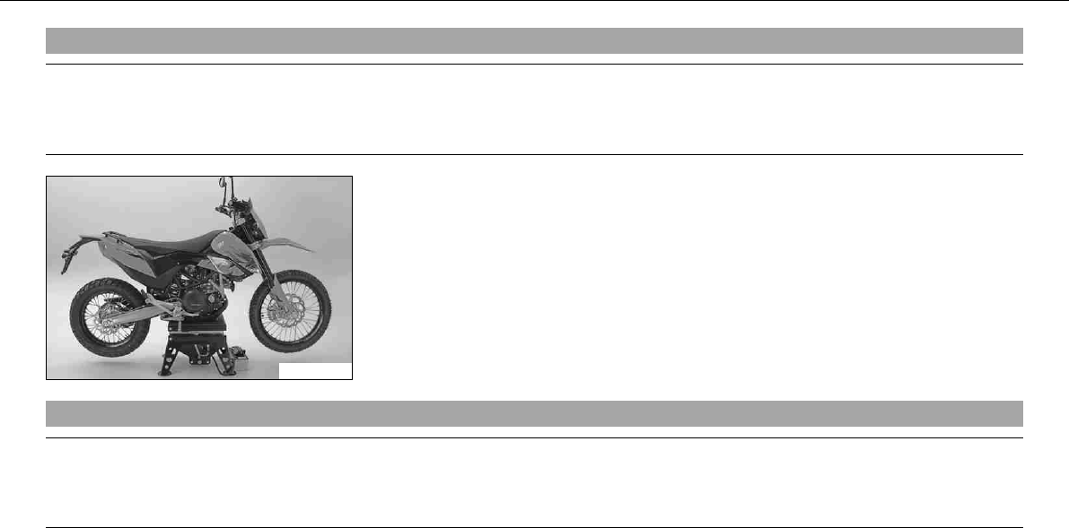
100241-01
–Jack up the motorcycle on the underride guard underneath the engine. The wheels must
no longer touch the ground.
–Secure the motorcycle against falling over.
9.2Removing the motorcycle from the work stand
Note
Danger of damage Danger of damage by the vehicle running away or falling over.
–Always place the vehicle on a firm and even surface.
–Remove the motorcycle from the work stand and rest it on its side stand.
–Remove the work stand.
MAINTENANCE WORK ON CHASSIS AND ENGINE 57
9.3Fork/shock absorber
100242-01
The fork and the shock absorber offer many options of adapting the chassis to your riding
style and the payload.
Info
To help you adapt the vehicle, we have summarized our findings in Table. You
can find the table on the underside of the seat.
These adjustments should be understood as a guideline and should always be the basis
of your own personal chassis adaptation. Do not change the adjustments at random or by
more than ± 40%, since otherwise the riding characteristics could deteriorate, particularly
at high speeds.
9.4Adjusting compression damping of fork
Info
The hydraulic compression damping determines the fork suspension behavior.
100243-10
–Remove protection covers.
–Turn adjusting screwsclockwise until they stop.
Info
The adjusting screws are located at the bottom end of the fork legs.
Make the same adjustment on both fork legs.
MAINTENANCE WORK ON CHASSIS AND ENGINE 58
–Turn back counterclockwise the number of clicks corresponding to the fork type.
Specification
Compression damping
Comfort 20clicks
Standard 15clicks
Sport 10clicks
full payload 10clicks
Info
Turn clockwise to increase damping, turn counterclockwise to reduce suspension
damping.
–Mount protection covers.
9.5Adjusting rebound damping of fork
Info
The hydraulic rebound damping determines the fork suspension behavior.
100244-10
–Turn adjusting screwsclockwise until they stop.
Info
The adjusting screws are located at the top end of the fork legs.
Make the same adjustment on both fork legs.
MAINTENANCE WORK ON CHASSIS AND ENGINE 59
–Turn back counterclockwise the number of clicks corresponding to the fork type.
Specification
Rebound damping
Comfort 20clicks
Standard 15clicks
Sport 10clicks
full payload 10clicks
Info
Turn clockwise to increase damping, turn counterclockwise to reduce suspension
damping.
9.6Compression damping of shock absorber
The shock absorber can regulate compression damping in low- and high-speed range separately (Dual Compression Control).
The term low and high speed refers to the movement of the shock absorber during compression and not the riding speed of the motorcycle.
The low- and high-speed technology works non-specifically.
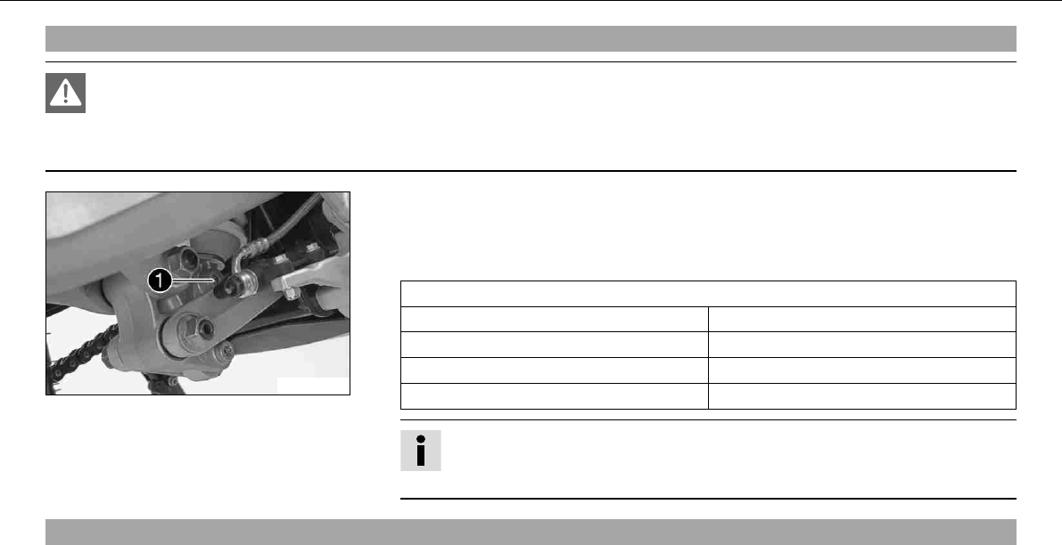
9.7Adjusting the low-speed compression damping of the shock absorber
Danger
Danger of accidents The shock absorber is under high pressure.
–The shock absorber is filled with highly compressed nitrogen, so never dismantle the shock absorber or carry out any mainte-
nance on it yourself.
Info
The low-speed setting can be seen during the slow to normal compression of the shock absorber.
MAINTENANCE WORK ON CHASSIS AND ENGINE 60
100245-10
–Turn the adjusting screwclockwise with a screwdriver until it stops.
Info
Do not loosen nut!
–Turn back counterclockwise the number of clicks corresponding to the shock absorber
type.
Specification
Compression damping, low-speed
Comfort 20clicks
Standard 15clicks
Sport 10clicks
full payload 10clicks
Info
Turn clockwise to increase damping, turn counterclockwise to reduce suspension
damping.
9.8Adjusting high-speed compression damping of the shock absorber
Danger
Danger of accidents The shock absorber is under high pressure.
–The shock absorber is filled with highly compressed nitrogen, so never dismantle the shock absorber or carry out any mainte-
nance on it yourself.
MAINTENANCE WORK ON CHASSIS AND ENGINE 61
Info
The high-speed setting can be seen during the fast compression of the shock absorber.
100246-10
–Turn the adjusting screwclockwise with an open-ended spanner until it stops.
Info
Do not loosen nut!
–Turn back counterclockwise the number of turns corresponding to the shock absorber
type.
Specification
Compression damping, high-speed
Comfort 2turns
Standard 1.5turns
Sport 1turn
full payload 1turn
Info
Turn clockwise to increase damping, turn counterclockwise to reduce suspension
damping.
MAINTENANCE WORK ON CHASSIS AND ENGINE 62
9.9Adjusting rebound damping of the shock absorber
Danger
Danger of accidents The shock absorber is under high pressure.
–The shock absorber is filled with highly compressed nitrogen, so never dismantle the shock absorber or carry out any mainte-
nance on it yourself.
100247-10
–Turn the adjusting screwclockwise until it stops.
–Turn back counterclockwise the number of clicks corresponding to the shock absorber
type.
Specification
Rebound damping
Comfort 20clicks
Standard 15clicks
Sport 10clicks
full payload 10clicks
Info
Turn clockwise to increase damping, turn counterclockwise to reduce suspension
damping.
9.10Bleeding fork legs
–Lean the motorcycle on the side stand.
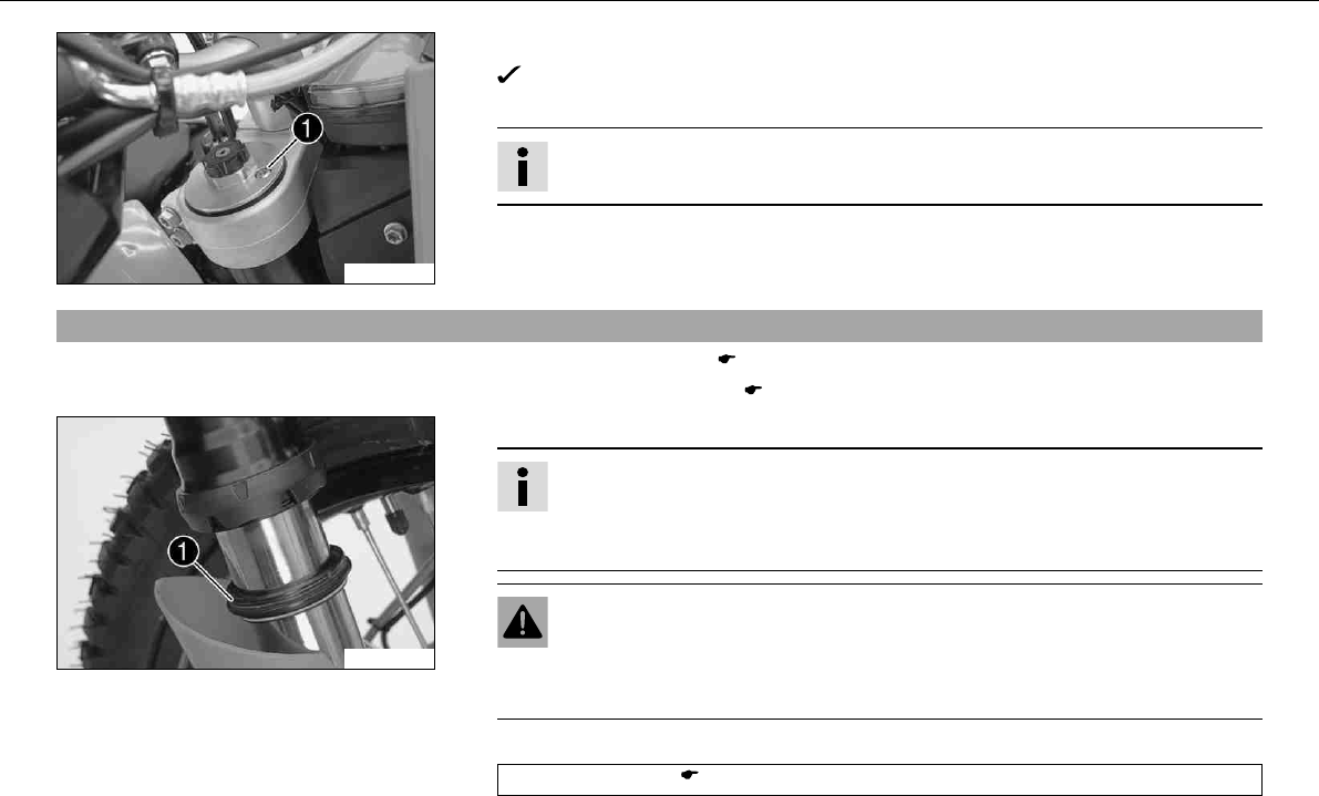
MAINTENANCE WORK ON CHASSIS AND ENGINE 63
100248-10
–Remove bleeder screwsbriefly.
Any excess pressure escapes from the interior of the fork.
–Mount and tighten bleeder screws.
Info
Carry out this action on both fork legs.
9.11Cleaning dust boots of fork legs
–Jack up the motorcycle. ( P. 56)
–Loosen the fork protection. ( P. 64)
100293-10
–Push dust bootsof both fork legs downwards.
Info
The dust boots should remove dust and coarse dirt particles from the fork tubes.
Over time, dirt can penetrate behind the dust boots. If this dirt is not removed,
the oil seals behind can start to leak.
Warning
Danger of accidents Reduced braking due to oil or grease on the brake discs.
–Always keep the brake discs free of oil and grease, and clean them with
brake cleaner when necessary.
–Clean and oil the dust boots and inner fork tube of both fork legs.
Universal oil spray ( P. 170)
–Press the dust boots back into their normal position.
MAINTENANCE WORK ON CHASSIS AND ENGINE 64
–Remove excess oil.
–Position the fork protection. ( P. 64)
–Remove the motorcycle from the work stand. ( P. 56)
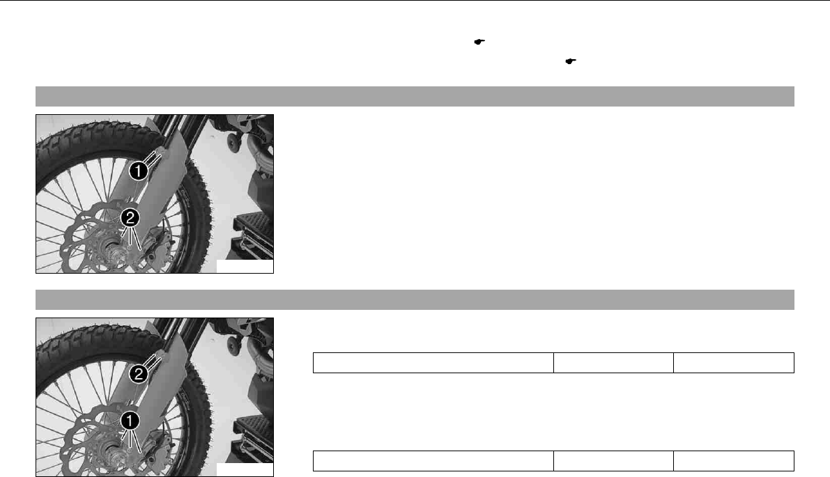
9.12Loosening the fork protection
100292-10
–Remove screwsand take off clamp.
–Remove screwson left fork leg. Push the fork protection downwards.
–Remove the screws on the right fork leg. Push the fork protection downwards.
9.13Positioning the fork protection
100292-11
–Position the fork protection on the left fork leg. Mount and tighten screws.
Specification
Remaining screws, chassis M6 10Nm (7.4lbfft)
–Position the brake line and cable harness. Put the clamp on, mount and tighten
screws.
–Position the fork protection on the right fork leg. Mount and tighten screws.
Specification
Remaining screws, chassis M6 10Nm (7.4lbfft)
MAINTENANCE WORK ON CHASSIS AND ENGINE 65
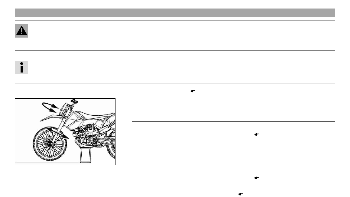
9.14Checking play of steering head bearingx
Warning
Danger of accidents Unsafe riding behavior due to incorrect steering head bearing play.
–The steering head bearing play should be adjusted immediately in an authorized KTM workshop.
Info
If the bike is driven for a longer time with play in the steering head bearing, the bearing and the bearing seats in the frame can be
damaged after time.
–Jack up the motorcycle. ( P. 56)
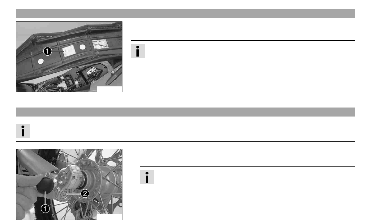
100298-10
–Move the handlebar to the straight-ahead position. Move the fork legs to and fro in the
direction of travel.
No play should be noticeable in the steering head bearing.
» If there is noticeable play present:
–Adjust play of the steering head bearing.x( P. 66)
–Move the handlebar to and fro over the entire steering range.
The handlebar must be able to move easily over the entire steering range. No resting
locations should be noticeable.
» If click positions are noticeable:
–Adjust play of the steering head bearing.x( P. 66)
–Check the steering head bearing and change if necessary.
–Remove the motorcycle from the work stand. ( P. 56)
MAINTENANCE WORK ON CHASSIS AND ENGINE 66
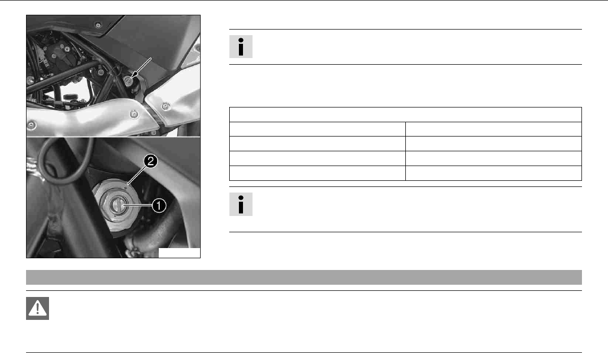
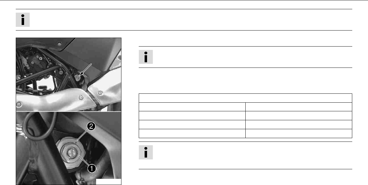
9.15Adjusting play of steering head bearingx
–Jack up the motorcycle. ( P. 56)
100297-10
–Loosen screw. Remove screw.
–Loosen and retighten screw.
Specification
Screw, top steering head M20x1.5 10Nm (7.4lbfft)
–Using a plastic hammer, tap lightly on the upper triple clamp to avoid strains.
–Fully tighten screw.
Specification
Screw, top triple clamp M8 17Nm (12.5lbfft)
–Mount and tighten screw.
Specification
Screw, steering stem M8 20Nm
(14.8lbfft)
Loctite®243™
–Check play of steering head bearing.x( P. 65)
–Remove the motorcycle from the work stand. ( P. 56)
0
0
BB
0
0
AA
MAINTENANCE WORK ON CHASSIS AND ENGINE 67
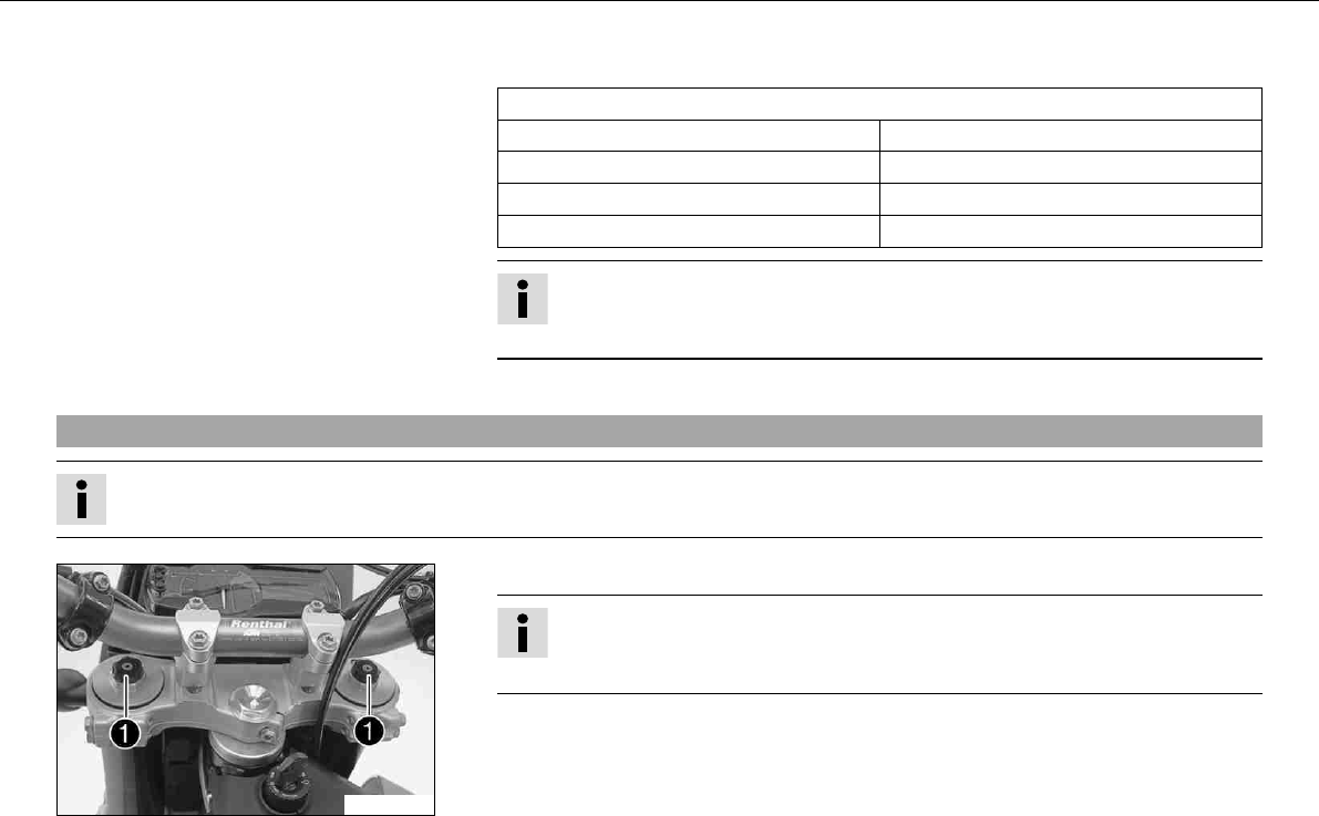
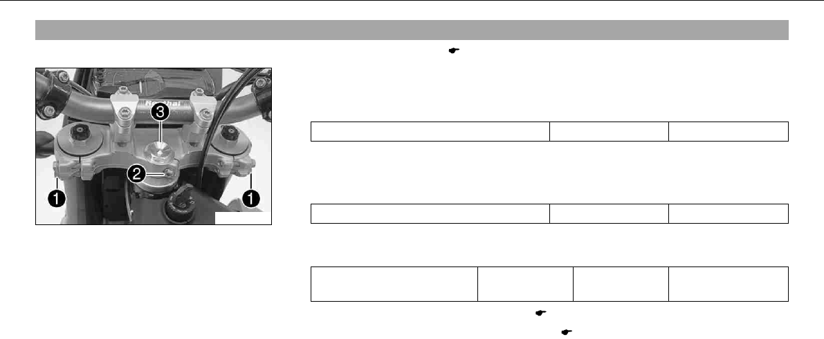
9.16Adjusting the handlebar anglex
100279-10
–Loosen screw.
–Move the handlebar to the desired position and slightly tichten the screws.
–Move the handlebar carefully in both directions as far as it will go.
» If the handlebar instruments touch the fuel tank:
–Correct the handlebar angle.
Info
The distance between the handlebar support and the handlebar clamp
must be the same at the front and rear.
–Fully tighten screw.
Specification
Screw, handlebar clamp M8 20Nm
(14.8lbfft)
Loctite®243™
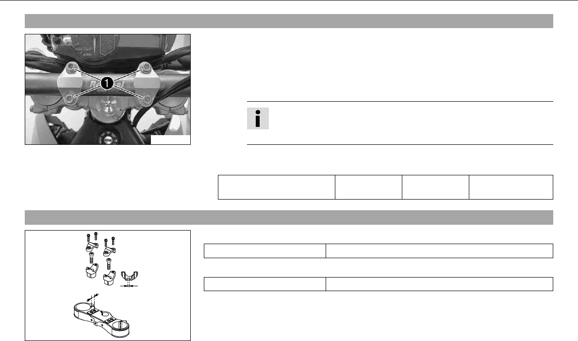
9.17Handlebar position
400271-11
On the upper triple clamp, there are 2 holes at a distanceto each other.
Distancebetween holes 15mm (0.59in)
The holes on the handlebar support are placed at a distancefrom the center.
Distancebetween holes 3.5mm (0.138in)
The handlebar can be mounted in 4 different positions. In this way, the handlebar can be
installed in the position most comfortable for the rider.
0
0
22
0
0
11
MAINTENANCE WORK ON CHASSIS AND ENGINE 68
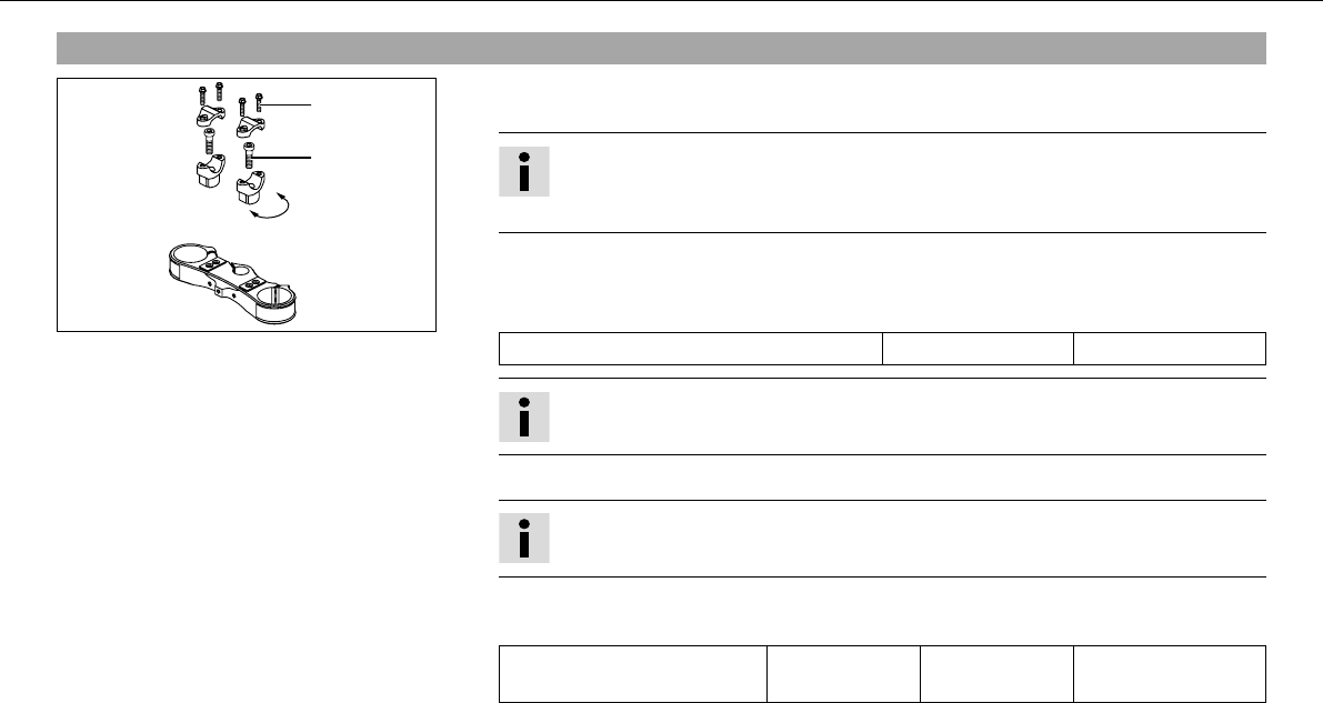
9.18Adjusting handlebar positionx
400271-10
–Remove the four screws. Remove the handlebar clamp. Remove the handlebar and
lay it to one side.
Info
Protect the motorcycle and its attachments from damage by covering them.
Do not bend the cables and lines.
–Remove the two screws. Remove the handlebar support.
–Place the handlebar support in the required position. Fit and tighten the two screws.
Specification
Screw, handlebar support M10 40Nm (29.5lbfft)
Info
Position the left and right handlebar supports evenly.
–Position the handlebar.
Info
Make sure cables and wiring are positioned correctly.
–Position the handlebar clamp. Fit and evenly tighten the four screws.
Specification
Screw, handlebar clamp M8 20Nm
(14.8lbfft)
Loctite®243™
MAINTENANCE WORK ON CHASSIS AND ENGINE 69
9.19Checking chain dirt
–Check the chain for coarse dirt accumulation.
» If the chain is very dirty:
–Clean the chain. ( P. 69)
9.20Cleaning the chain
Warning
Danger of accidents Oil or grease on the tires reduces their grip.
–Remove oil and grease with a suitable cleaning material.
Warning
Danger of accidents Reduced braking due to oil or grease on the brake discs.
–Always keep the brake discs free of oil and grease, and clean them with brake cleaner when necessary.
Warning
Environmental hazard Problem materials cause environmental damage.
–Dispose of oil, grease, filters, fuel, cleaning substances, brake fluid, batteries, etc. according to regulations.
Info
The service life of the chain depends largely on its maintenance.
–Clean the chain regularly.
–Rinse off loose dirt with a soft jet of water.
–Remove old grease remains with chain cleaner.
Chain cleaner ( P. 169)
MAINTENANCE WORK ON CHASSIS AND ENGINE 70
–After drying, apply chain spray.
Offroad chain spray ( P. 170)
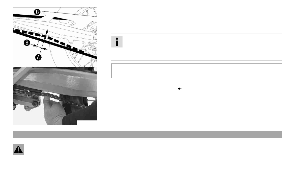
9.21Checking the chain tension
Warning
Danger of accidents Danger caused by incorrect chain tension.
–If the chain tension is too high, the components of the secondary power train (chain, engine sprocket, rear sprocket, bearings
in transmission and rear wheel) are under additional load. Apart from premature wear, in extreme cases the chain can rupture
or the countershaft of the transmission can break. On the other hand, if the chain is loose, it can fall off the engine sprocket or
the rear sprocket and block the rear wheel or damage the engine. Check for correct chain tension and adjust if necessary.
MAINTENANCE WORK ON CHASSIS AND ENGINE 71
100249-10
–Lean the motorcycle on the side stand.
–Shift gear to neutral.
–Push the chain upward at a distancefrom the chain sliding guard and determine the
chain tension.
Info
The upper chain sectionmust be taut.
Chain wear is not always even, so you should repeat this measurement at differ-
ent chain positions.
Chain tension 5mm (0.2in)
Distance to chain sliding guard 30mm (1.18in)
» If the chain tension does not meet specifications:
–Adjust the chain tension. ( P. 71)
9.22Adjusting chain tension
Warning
Danger of accidents Danger caused by incorrect chain tension.
–If the chain tension is too high, the components of the secondary power train (chain, engine sprocket, rear sprocket, bearings
in transmission and rear wheel) are under additional load. Apart from premature wear, in extreme cases the chain can rupture
or the countershaft of the transmission can break. On the other hand, if the chain is loose, it can fall off the engine sprocket or
the rear sprocket and block the rear wheel or damage the engine. Check for correct chain tension and adjust if necessary.
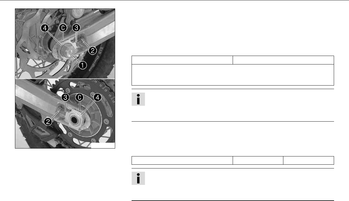
MAINTENANCE WORK ON CHASSIS AND ENGINE 72
100250-10
–Lean the motorcycle on the side stand.
–Shift gear to neutral.
–Loosen nut.
–Loosen nuts.
–Adjust the chain tension by turning the adjusting screwsleft and right.
Specification
Chain tension 5mm (0.2in)
Turn the adjusting screwsleft and right so that the markings on the left and right
chain adjustersare in the same position relative to the reference marks. The
rear wheel is then correctly aligned.
Info
The upper chain section must be taut.
Chain wear is not always even, so you should repeat this measurement at differ-
ent chain positions.
–Tighten nuts.
–Make sure that the chain adjustersare fitted correctly on the adjusting screws.
–Tighten nut.
Specification
Nut, rear wheel spindle M25x1.5 90Nm (66.4lbfft)
Info
The wide adjustment range of the chain adjusters (32 mm) enables different
secondary transmissions with the same chain length.
The chain adjusterscan be turned by 180°.
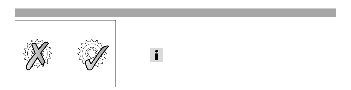
MAINTENANCE WORK ON CHASSIS AND ENGINE 73
9.23Checking rear sprocket / engine sprocket for wear
100132-10
–Check rear sprocket / engine sprocket for wear.
» If the rear sprocket / engine sprocket are worn:
–Replace rear sprocket / engine sprocket.
Info
The engine sprocket, rear sprocket and chain should always be replaced
together.
For safety reasons, the chain has no chain joint. Always have the chain
replaced in an authorized KTM workshop, where the necessary chain
rivet tool is available.
–Check chain guides for tightness and wear.
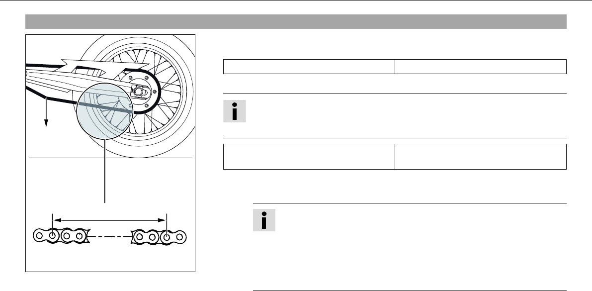
B
1 2 3 16 17 18
A
MAINTENANCE WORK ON CHASSIS AND ENGINE 74
9.24Checking chain wear
400409-10
–Shift into neutral, pull the lower chain section with the specified weight.
Specification
Weight of chain wear measurement 15kg (33lb.)
–Measure the distanceof 18 chain links in the lower chain section.
Info
Chain wear is not always even, so you should repeat this measurement at differ-
ent chain positions.
Maximum distanceat the longest
chain section
272mm (10.71in)
» If the distanceis greater than the specified measurement:
–Have the chain changed.
Info
When the chain is replaced, the rear sprocket and engine sprocket
should also be changed.
New chains wear out faster on old, worn sprockets.
For safety reasons, the chain has no chain joint. Always have the chain
changed in an authorized KTM workshop, where the necessary tool is
available.
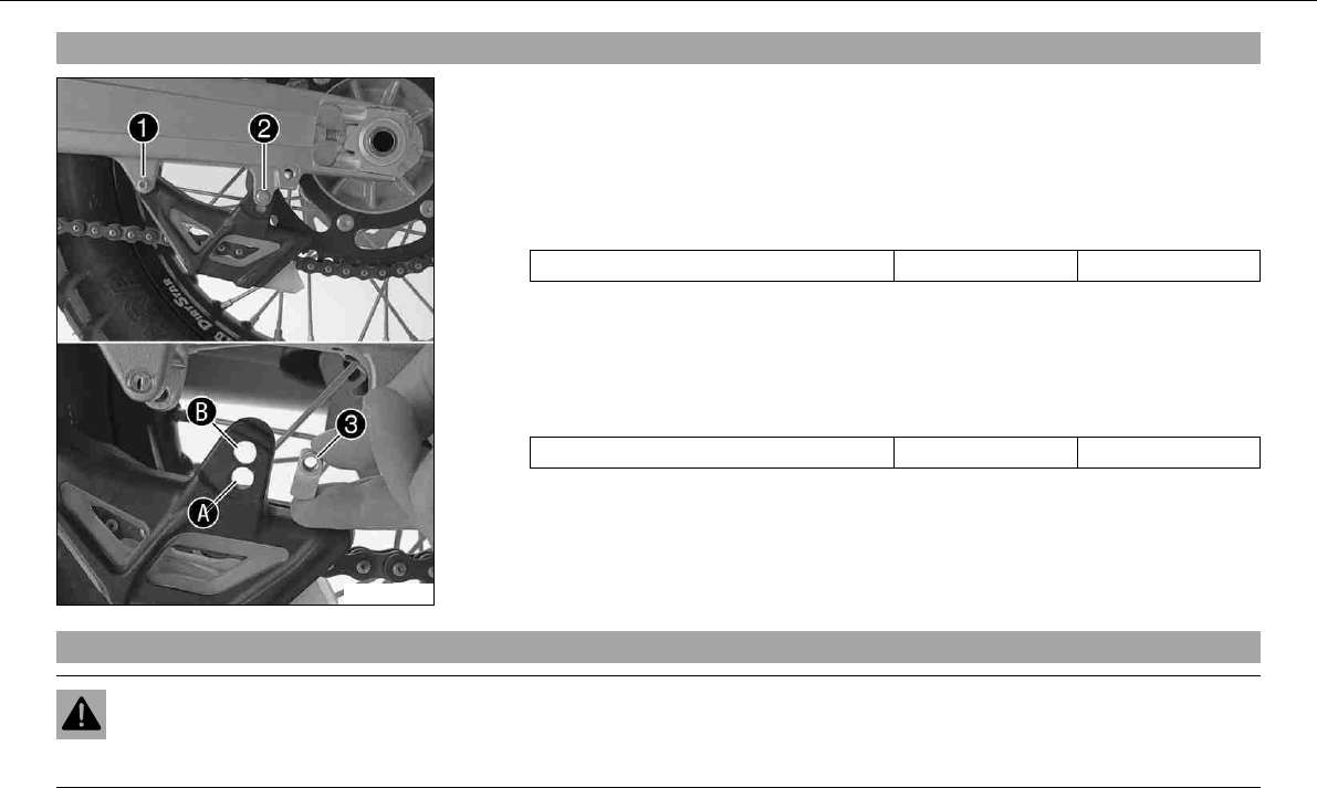
MAINTENANCE WORK ON CHASSIS AND ENGINE 75
9.25Adjusting chain guidex
100299-10
–Remove screwsand. Take off the chain guide.
Conditions
Number of teeth: ≤44teeth
–Insert nutin hole. Position the chain guide.
–Mount and tighten screwsand.
Specification
Remaining screws, chassis M6 10Nm (7.4lbfft)
Conditions
Number of teeth: ≥45teeth
–Insert nutin hole. Position the chain guide.
–Mount and tighten screwsand.
Specification
Remaining screws, chassis M6 10Nm (7.4lbfft)
9.26Checking brake discs
Warning
Danger of accidents Reduced braking due to worn brake discs.
–Worn brake discs should be replaced immediately in an authorized KTM workshop.
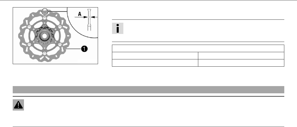
MAINTENANCE WORK ON CHASSIS AND ENGINE 76
400406-10
–Check the thickness of the front and rear brake discs at several places on the disc to
see if it conforms to measurement.
Info
Wear reduces the thickness of the brake disc around the area used by the brake
linings..
Wear limit of brake discs
front 4.5mm (0.177in)
Rear 3.5mm (0.138in)
» If the brake disc thickness is less than the specified value:
–Change the brake disc.
9.27Checking free play of hand brake lever
Warning
Danger of accidents Brake system failure.
–If there is no free travel on the hand brake lever, pressure builds up on the front brake in the brake system. The front brake can
fail due to overheating. Adjust free travel on hand brake lever according to specifications.
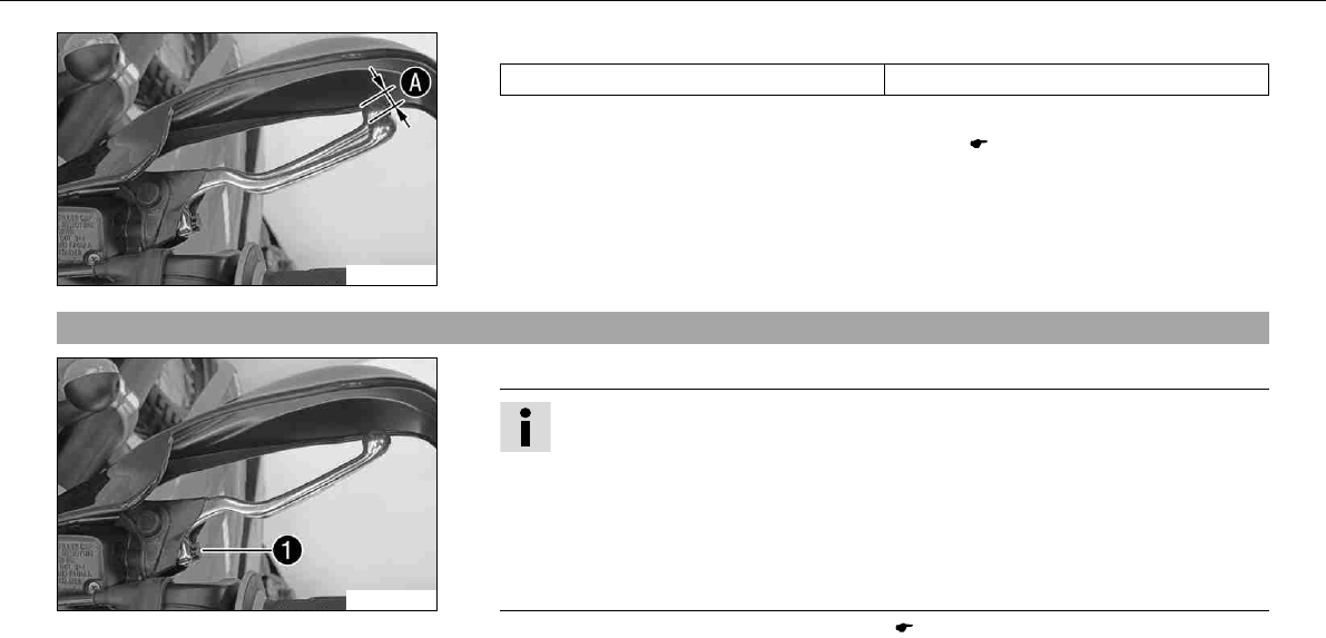
MAINTENANCE WORK ON CHASSIS AND ENGINE 77
100251-10
–Push the hand brake to the handlebar and check free play.
Free play of hand brake lever ≥3mm (≥0.12in)
» If the free travel does not meet specifications:
–Adjust the free travel of the handbrake lever. ( P. 77)
9.28Adjusting free travel of handbrake lever
100252-10
–Adjust the free travel of the handbrake lever with the adjustment screw.
Info
Turn the adjustment screw clockwise to reduce free travel. The pressure point
moves away from the handlebar.
Turn the adjustment screw counterclockwise to increase free travel. The pressure
point moves towards the handlebar.
The range of adjustment is limited.
Turn the adjusting screw by hand only, and do not apply any force.
Do not make any adjustments while riding!
–Check the free play of the hand brake lever. ( P. 76)
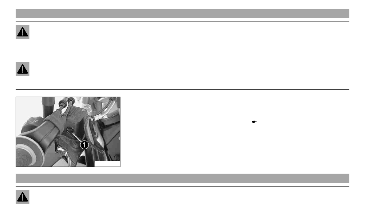
MAINTENANCE WORK ON CHASSIS AND ENGINE 78
9.29Checking front brake fluid level
Warning
Danger of accidents Brake system failure.
–MINIf the brake fluid level falls below the MIN mark, this indicates a leakage in the brake system or worn-out brake linings.
Have the brake system checked in an authorized KTM workshop, and do not ride any further.
Warning
Danger of accidents Reduced braking due to old brake fluid.
–Have the front and rear brake fluid replaced according to the service plan in an authorized KTM workshop.
100253-10
–The brake fluid level must not fall below the center of the level viewerwhen the
brake fluid reservoir is vertical.
» If the brake fluid level is lower than the center of the level viewer:
–Add brake fluid for the front brake.x( P. 78)
9.30Adding brake fluid for front brakex
Warning
Danger of accidents Brake system failure.
–MINIf the brake fluid level falls below the MIN mark, this indicates a leakage in the brake system or worn-out brake linings.
Have the brake system checked in an authorized KTM workshop, and do not ride any further.
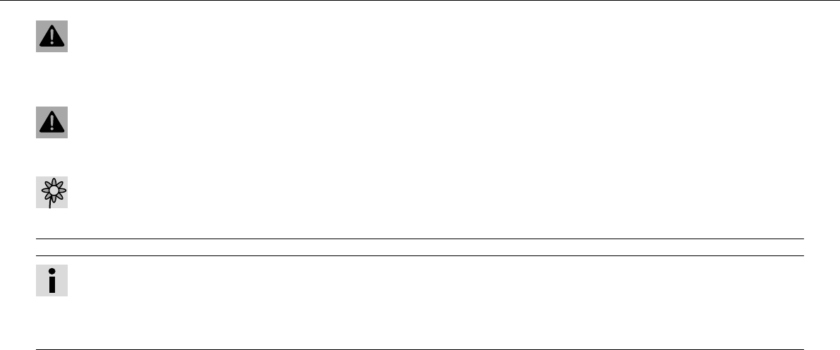
MAINTENANCE WORK ON CHASSIS AND ENGINE 79
Warning
Skin irritations Brake fluid can cause skin irritation on contact.
–Avoid contact with skin and eyes, and keep out of the reach of children.
–If brake fluid gets into your eyes, rinse thoroughly with water and contact a doctor immediately.
Warning
Danger of accidents Reduced braking due to old brake fluid.
–Have the front and rear brake fluid replaced according to the service plan in an authorized KTM workshop.
Warning
Environmental hazard Problem materials cause environmental damage.
–Dispose of oil, grease, filters, fuel, cleaning substances, brake fluid, batteries, etc. according to regulations.
Info
Never user DOT5 brake fluid! It is based on silicone oil and is colored purple. Oil seals and brake lines are not designed for DOT5
brake fluid.
Avoid contact between brake fluid and painted parts. Brake fluid attacks paint!
Use only clean brake fluid from a sealed container!
–Move the brake fluid reservoir mounted on the handlebar to a horizontal position.
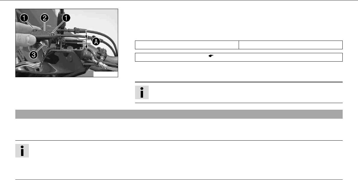
MAINTENANCE WORK ON CHASSIS AND ENGINE 80
100254-10
–Remove screws.
–Remove coverwith membrane.
–Add brake fluid to level.
Specification
Measurement of5mm (0.2in)
Brake fluid DOT4/DOT5.1 ( P. 166)
–Check parts for damage and wear. Replace damaged or worn parts.
–Position the cover with the membrane. Mount and tighten screws.
Info
Clean up overflowed or spilt brake fluid immediately with water.
9.31Brake linings
The brake linings fitted by KTM were tested over long periods and ensure optimal braking properties. The type names of brake pads are
entered in the homologation documents.
Info
Brake linings available from accessory suppliers are often not tested and approved for use on KTM vehicles. The construction and
friction factor of the brake linings and therefore the brake power can differ considerably from the original KTM brake linings. If
brake linings are used that differ from the originals, there is no guarantee that they comply with the original license. The vehicle
no longer corresponds to the condition at delivery, and the warranty is no longer valid.
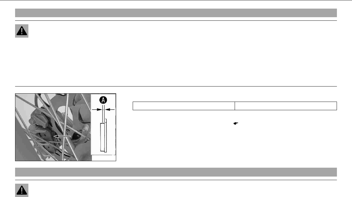
MAINTENANCE WORK ON CHASSIS AND ENGINE 81
9.32Checking the front brake linings
Warning
Danger of accidents Reduced braking due to worn brake linings.
–Worn brake linings should be replaced immediately in an authorized KTM workshop.
Note
Danger of accidents Reduced braking due to damaged brake discs.
–If the brake linings are not changed in time, the steel brake lining carriers grind on the brake disc. The braking effect is greatly
reduced and the brake discs are destroyed.
100255-10
–Check the brake linings for minimum thickness.
Minimum thickness≥1mm (≥0.04in)
» If the minimum thickness is less than specified:
–Change the front brake linings.x( P. 81)
9.33Changing the front brake liningsx
Warning
Danger of accidents Improper brake maintenance and repair.
–Always have your brake system maintained and repaired in an authorized KTM workshop.

MAINTENANCE WORK ON CHASSIS AND ENGINE 82
Warning
Skin irritations Brake fluid can cause skin irritation on contact.
–Avoid contact with skin and eyes, and keep out of the reach of children.
–If brake fluid gets into your eyes, rinse thoroughly with water and contact a doctor immediately.
Warning
Danger of accidents Reduced braking due to old brake fluid.
–Have the front and rear brake fluid replaced according to the service plan in an authorized KTM workshop.
Warning
Danger of accidents Reduced braking due to oil or grease on the brake discs.
–Always keep the brake discs free of oil and grease, and clean them with brake cleaner when necessary.
Warning
Danger of accidents Reduced braking due to use of non-approved brake linings.
–Brake linings available from accessory suppliers are often not tested and approved for use on KTM vehicles. The construction
and friction factor of the brake linings and therefore the brake power can differ considerably from the original KTM brake lin-
ings. If brake linings are used that differ from the originals, there is no guarantee that they comply with the original license.
The vehicle no longer corresponds to the condition at delivery, and the warranty is no longer valid.
Warning
Environmental hazard Problem materials cause environmental damage.
–Dispose of oil, grease, filters, fuel, cleaning substances, brake fluid, batteries, etc. according to regulations.
Info
Never user DOT5 brake fluid! This is based on silicone oil and is colored purple. Oil seals and brake lines are not designed for
DOT5 brake fluid.
Avoid contact between brake fluid and painted parts. Brake fluid attacks paint!
Use only clean brake fluid from a sealed container!
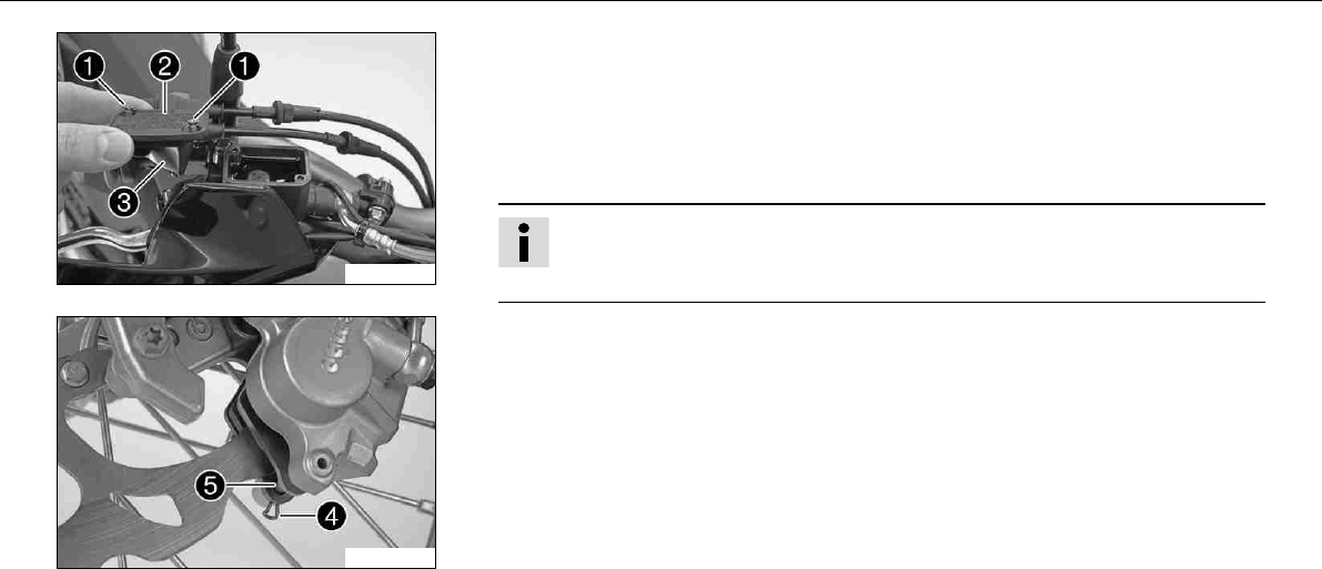
MAINTENANCE WORK ON CHASSIS AND ENGINE 83
100254-11
–Move the brake fluid reservoir mounted on the handlebar to a horizontal position.
–Remove screws.
–Remove the coverwith membrane.
–Press the brake caliper by hand on to the brake disc in order to press back the brake
pistons. Ensure that brake fluid does not overflow from the brake fluid reservoir and
suction it off if necessary.
Info
Make sure when pushing back the brake pistons that you do not press the brake
caliper against the spokes.
100290-10
–Remove split pin, remove bolttoward the right by striking it and remove the brake
linings.
–Clean brake caliper and brake caliper support.
–Check parts for damage and wear. Replace damaged or worn parts.
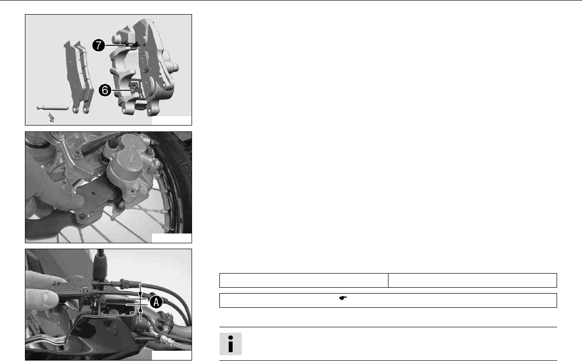
MAINTENANCE WORK ON CHASSIS AND ENGINE 84
400418-10
–Check that leaf springin the brake caliper and sliding platein the brake caliper
support are seated correctly.
100291-01
–Insert the brake pads, insert the bolt and mount the split pin.
–Operate the hand brake lever repeatedly until the brake linings lie on the brake disc and
there is a tight spot.
100254-12
–Adjust the brake fluid level to level.
Specification
Measurement of5mm (0.2in)
Brake fluid DOT4/DOT5.1 ( P. 166)
–Position the cover with the membrane. Mount and tighten screws.
Info
Clean up overflowed or spilt brake fluid immediately with water.
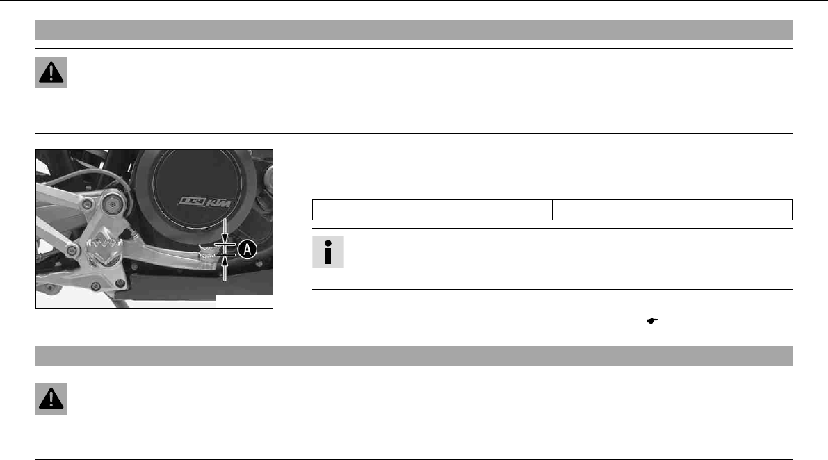
MAINTENANCE WORK ON CHASSIS AND ENGINE 85
9.34Checking free play of foot brake lever
Warning
Danger of accidents Brake system failure.
–If there is no free travel on the foot brake pedal, pressure builds up on the rear brake in the brake system. The rear brake can
fail due to overheating. Adjust free travel on foot brake pedal according to specifications.
100256-10
–Move the foot brake lever back and forth between the end stop and the contact to the
foot brake cylinder piston and check free travel.
Specification
Free play at foot brake lever 3… 5mm (0.12… 0.2in)
Info
You will know that contact has been made with the foot brake cylinder piston
when there is increased resistance when you activate the foot brake pedal.
» If the free travel does not meet specifications:
–Adjust the basic position of the foot brake pedal.x( P. 85)
9.35Adjusting basic position of foot brake pedalx
Warning
Danger of accidents Brake system failure.
–If there is no free travel on the foot brake pedal, pressure builds up on the rear brake in the brake system. The rear brake can
fail due to overheating. Adjust free travel on foot brake pedal according to specifications.
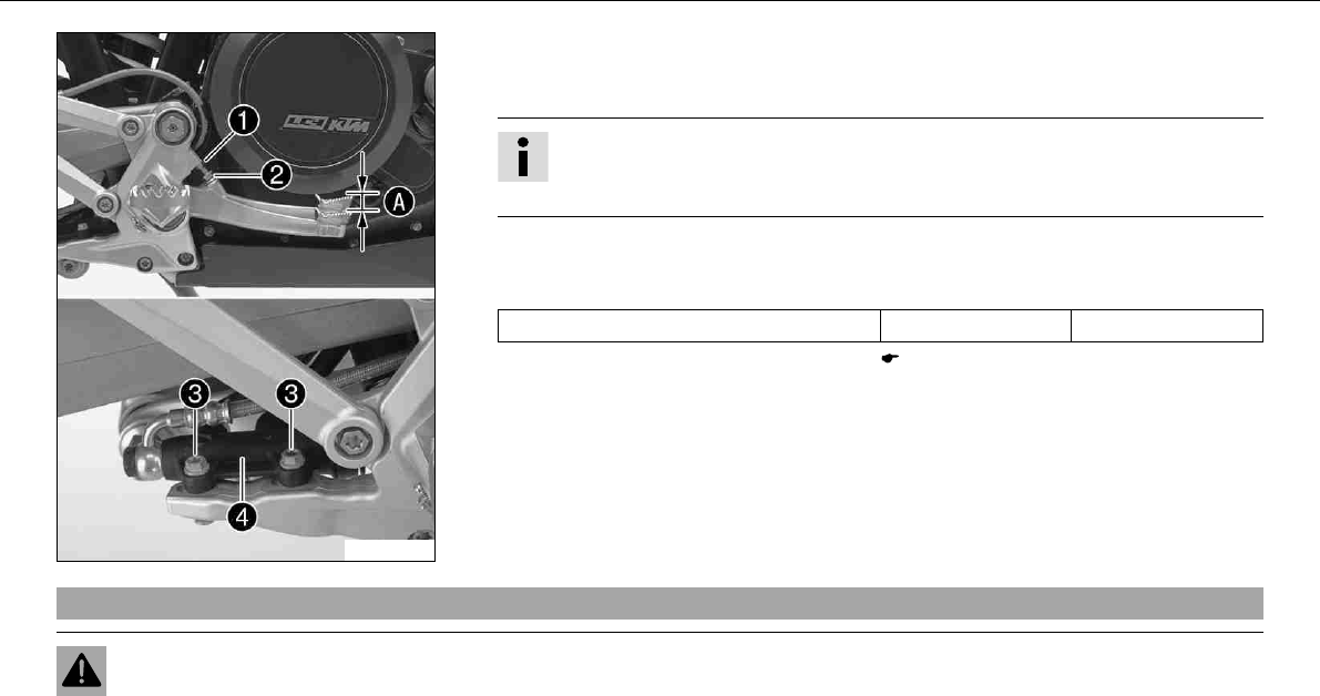
MAINTENANCE WORK ON CHASSIS AND ENGINE 86
100257-10
–Remove screw connectionon foot brake cylinder.
–To adjust the basic position of the foot brake pedal as needed, loosen nutand turn
screwaccordingly.
Info
The range of adjustment is limited. The screw must be screwed into the footrest
bracket by at least four turns.
–Position foot brake cylinderso that the foot brake pedal has the necessary free travel.
Hold screwsin place and tighten the nuts.
Specification
Nut, foot brake cylinder screw M6 10Nm (7.4lbfft)
–Check the free play of the foot brake lever. ( P. 85)
–Tighten nut.
9.36Checking rear brake fluid level
Warning
Danger of accidents Brake system failure.
–MINIf the brake fluid level falls below the MIN mark, this indicates a leakage in the brake system or worn-out brake linings.
Have the brake system checked in an authorized KTM workshop, and do not ride any further.
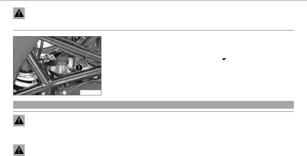
MAINTENANCE WORK ON CHASSIS AND ENGINE 87
Warning
Danger of accidents Reduced braking due to old brake fluid.
–Have the front and rear brake fluid replaced according to the service plan in an authorized KTM workshop.
100258-10
–Stand the vehicle upright.
–Check the brake fluid level in the brake fluid reservoir.
» If the fluid level reaches theMINmarking:
–Top up the brake fluid of the rear brake.x( P. 87)
9.37Topping up brake fluid of rear brakex
Warning
Danger of accidents Brake system failure.
–MINIf the brake fluid level falls below the MIN mark, this indicates a leakage in the brake system or worn-out brake linings.
Have the brake system checked in an authorized KTM workshop, and do not ride any further.
Warning
Skin irritations Brake fluid can cause skin irritation on contact.
–Avoid contact with skin and eyes, and keep out of the reach of children.
–If brake fluid gets into your eyes, rinse thoroughly with water and contact a doctor immediately.
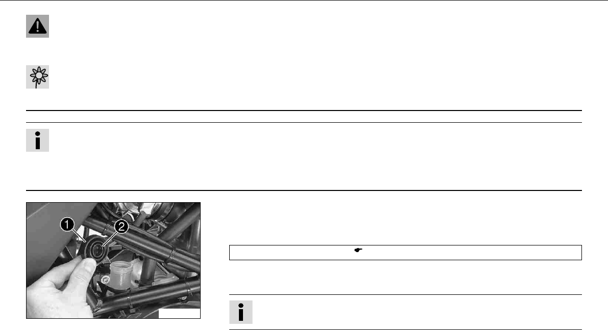
MAINTENANCE WORK ON CHASSIS AND ENGINE 88
Warning
Danger of accidents Reduced braking due to old brake fluid.
–Have the front and rear brake fluid replaced according to the service plan in an authorized KTM workshop.
Warning
Environmental hazard Problem materials cause environmental damage.
–Dispose of oil, grease, filters, fuel, cleaning substances, brake fluid, batteries, etc. according to regulations.
Info
Never user DOT5 brake fluid! This is based on silicone oil and is colored purple. Oil seals and brake lines are not designed for
DOT5 brake fluid.
Avoid contact between brake fluid and painted parts. Brake fluid attacks paint!
Use only clean brake fluid from a sealed container!
100259-10
–Stand the vehicle upright.
–Remove screw coverwith membrane.
–Top up the brake fluid toMAX level.
Brake fluid DOT4/DOT5.1 ( P. 166)
–Check parts for damage and wear. Replace damaged or worn parts.
–Refit screw with membrane.
Info
Clean up overflowed or spilt brake fluid immediately with water.
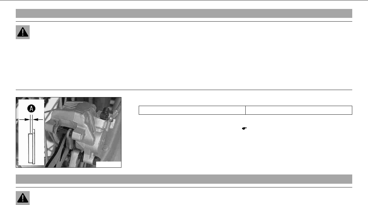
MAINTENANCE WORK ON CHASSIS AND ENGINE 89
9.38Checking the rear brake linings
Warning
Danger of accidents Reduced braking due to worn brake linings.
–Worn brake linings should be replaced immediately in an authorized KTM workshop.
Note
Danger of accidents Reduced braking due to damaged brake discs.
–If the brake linings are not changed in time, the steel brake lining carriers grind on the brake disc. The braking effect is greatly
reduced and the brake discs are destroyed.
100260-10
–Check the brake linings for minimum thickness.
Minimum thickness≥1mm (≥0.04in)
» If the minimum thickness is less than specified:
–Change the rear brake linings.x( P. 89)
9.39Changing rear brake liningsx
Warning
Danger of accidents Improper brake maintenance and repair.
–Always have your brake system maintained and repaired in an authorized KTM workshop.
MAINTENANCE WORK ON CHASSIS AND ENGINE 90
Warning
Skin irritations Brake fluid can cause skin irritation on contact.
–Avoid contact with skin and eyes, and keep out of the reach of children.
–If brake fluid gets into your eyes, rinse thoroughly with water and contact a doctor immediately.
Warning
Danger of accidents Reduced braking due to old brake fluid.
–Have the front and rear brake fluid replaced according to the service plan in an authorized KTM workshop.
Warning
Danger of accidents Reduced braking due to oil or grease on the brake discs.
–Always keep the brake discs free of oil and grease, and clean them with brake cleaner when necessary.
Warning
Danger of accidents Reduced braking due to use of non-approved brake linings.
–Brake linings available from accessory suppliers are often not tested and approved for use on KTM vehicles. The construction
and friction factor of the brake linings and therefore the brake power can differ considerably from the original KTM brake lin-
ings. If brake linings are used that differ from the originals, there is no guarantee that they comply with the original license.
The vehicle no longer corresponds to the condition at delivery, and the warranty is no longer valid.
Warning
Environmental hazard Problem materials cause environmental damage.
–Dispose of oil, grease, filters, fuel, cleaning substances, brake fluid, batteries, etc. according to regulations.
Info
Never user DOT5 brake fluid! This is based on silicone oil and is colored purple. Oil seals and brake lines are not designed for
DOT5 brake fluid.
Avoid contact between brake fluid and painted parts. Brake fluid attacks paint!
Use only clean brake fluid from a sealed container!
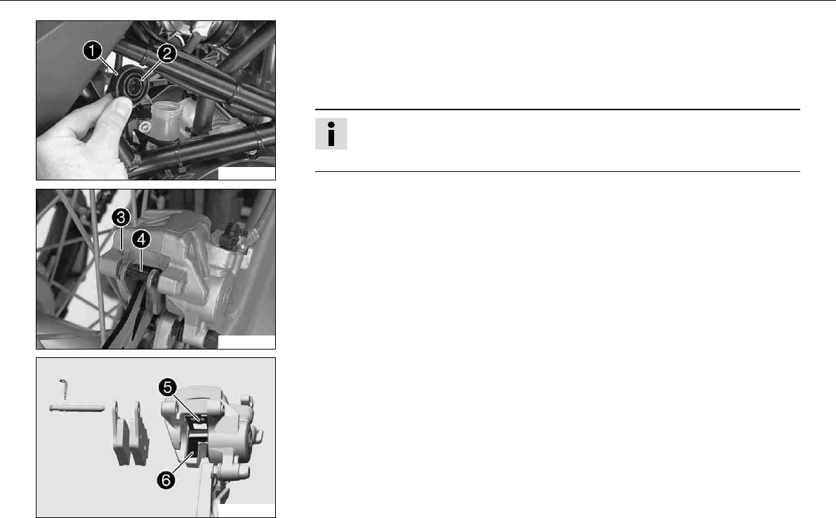
MAINTENANCE WORK ON CHASSIS AND ENGINE 91
100259-10
–Stand the vehicle upright.
–Remove screw coverwith membrane.
–Press the brake caliper by hand on to the brake disc in order to press back the brake
piston. Ensure that brake fluid does not overflow from the brake fluid reservoir and suc-
tion it off if necessary.
Info
Make sure when pushing back the brake piston that you do not press the brake
caliper against the spokes.
100288-10
–Remove split pin, remove bolttoward the left by striking it and remove the brake
linings.
–Clean brake caliper and brake caliper support.
–Check parts for damage and wear. Replace damaged or worn parts.
400419-10
–Check that leaf springin the brake caliper and sliding platein the brake caliper
support are seated correctly.
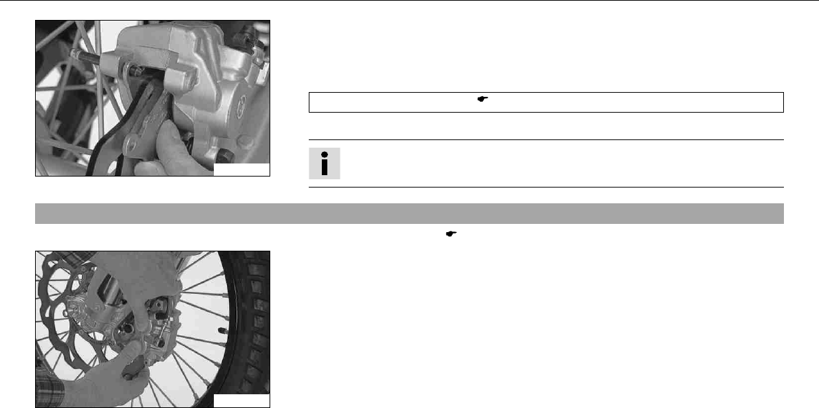
MAINTENANCE WORK ON CHASSIS AND ENGINE 92
100289-01
–Insert the brake pads, insert the bolt and mount the split pin.
–Operate the foot brake lever repeatedly until the brake linings lie on the brake disc and
there is a tight spot.
–Adjust the brake fluid level to the MAXmark.
Brake fluid DOT4/DOT5.1 ( P. 166)
–Refit screw with membrane.
Info
Clean up overflowed or spilt brake fluid immediately with water.
9.40Removing front wheelx
–Jack up the motorcycle. ( P. 56)
100261-01
–Press the brake caliper by hand on to the brake disc in order to press back the brake
pistons.
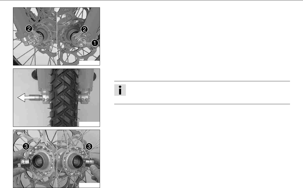
MAINTENANCE WORK ON CHASSIS AND ENGINE 93
100262-10
–Remove screw.
–Loosen screw.
100263-10
–Holding the front wheel, withdraw the wheel spindle. Take the front wheel out of the
fork.
Info
Do not pull the hand brake lever when the front wheel is removed.
Always lay the wheel down in such a way that the brake disc is not damaged.
100264-10
–Remove the spacing sleeves.
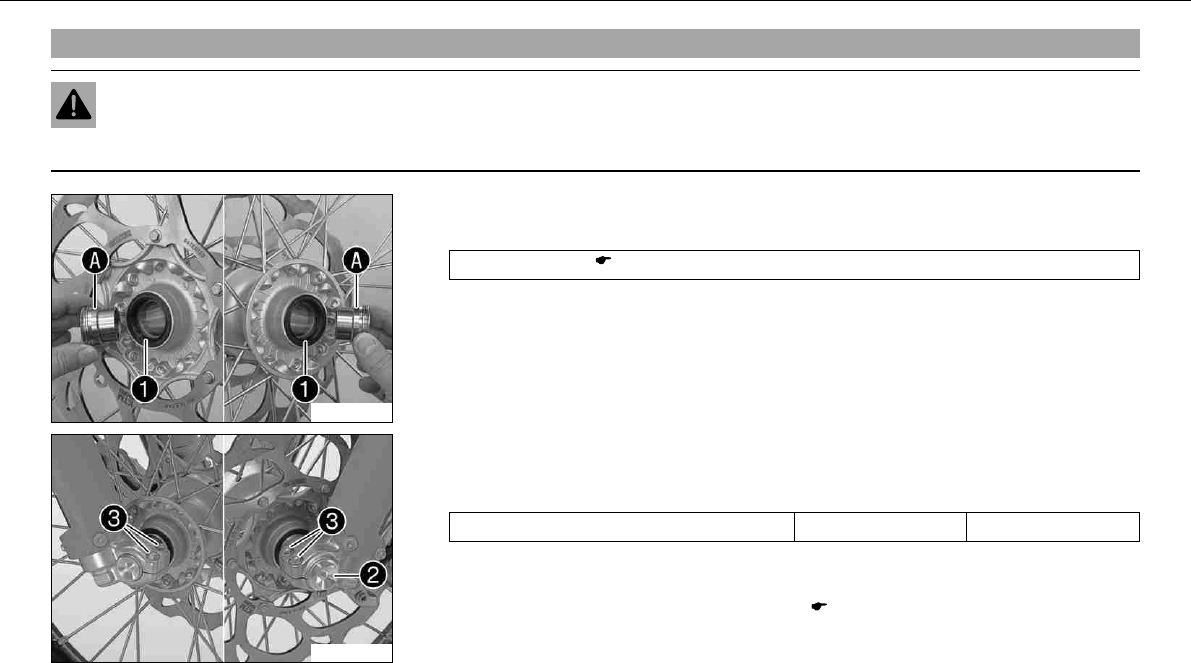
MAINTENANCE WORK ON CHASSIS AND ENGINE 94
9.41Fitting front wheelx
Warning
Danger of accidents Reduced braking due to oil or grease on the brake discs.
–Always keep the brake discs free of oil and grease, and clean them with brake cleaner when necessary.
100265-10
–Check parts for damage and wear. Replace damaged or worn parts.
–Clean and grease shaft seal ringsand bearing surfaceof the spacing sleeves.
Long-life grease ( P. 170)
–Fit the spacing sleeves.
100266-10
–Lift the front wheel into the fork, position it, and insert the wheel spindle.
–Mount and tighten screw.
Specification
Screw, front wheel spindle M24x1.5 40Nm (29.5lbfft)
–Operate the hand brake lever several times until the brake pads are lying correctly on
the brake disc.
–Remove the motorcycle from the work stand. ( P. 56)
–Pull the front wheel brake and push down hard on the fork several times to align the
fork legs.
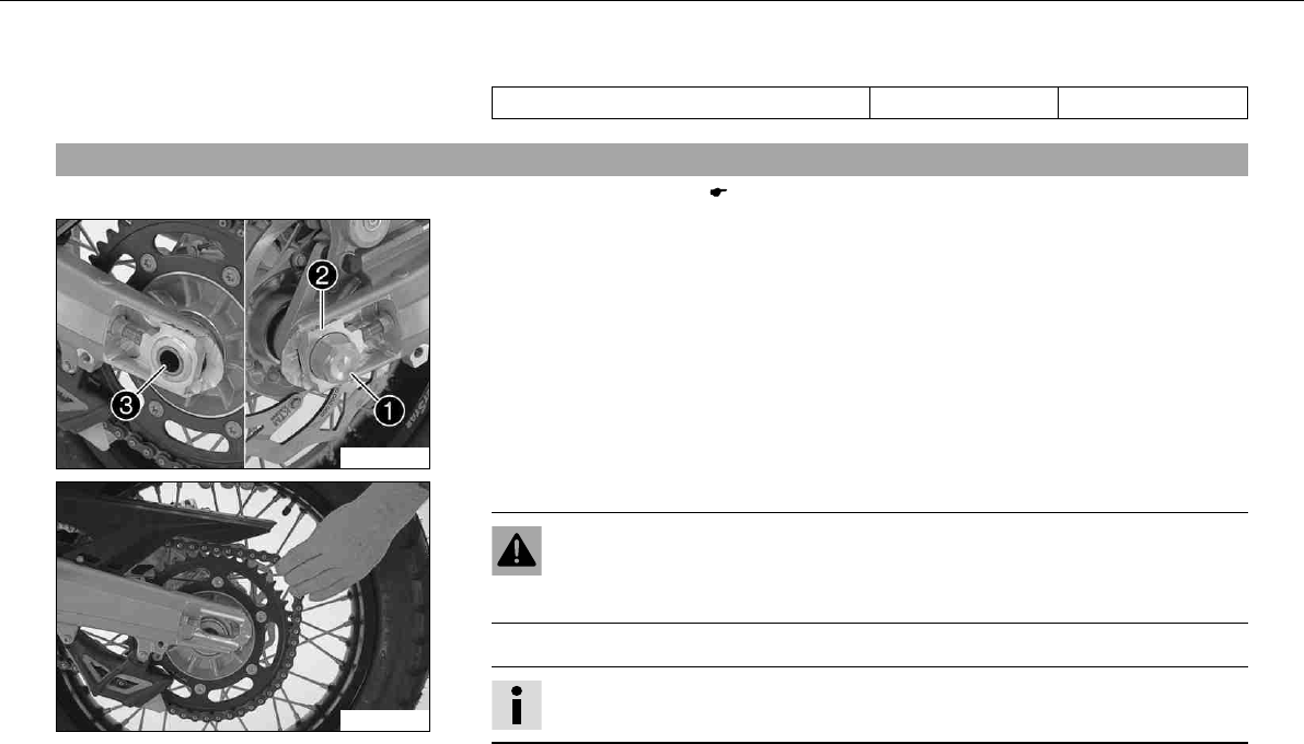
MAINTENANCE WORK ON CHASSIS AND ENGINE 95
–Fully tighten screw.
Specification
Screw, fork stub M8 15Nm (11.1lbfft)
9.42Removing rear wheelx
–Jack up the motorcycle. ( P. 56)
100267-10
–Press the brake caliper by hand on to the brake disc in order to press back the brake
piston.
–Remove nut. Remove chain adjuster.
–Holding the rear wheel, withdraw the wheel spindle.
100268-01
–Push the rear wheel forwards as far as possible and take the chain off the rear sprocket.
Warning
Danger of accidents Reduced braking due to damaged brake discs.
–Always lay the wheel down in such a way that the brake disc is not damaged.
–Take the rear wheel out of the swing arm.
Info
Do not operate the foot brake when the rear wheel is removed.
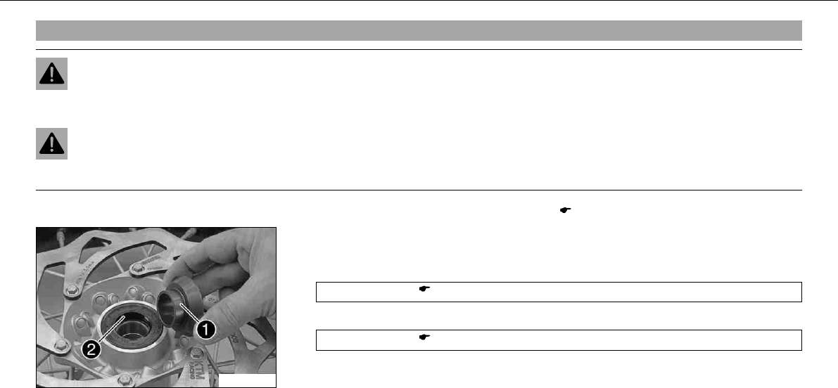
MAINTENANCE WORK ON CHASSIS AND ENGINE 96
9.43Fitting rear wheelx
Warning
Danger of accidents Reduced braking due to oil or grease on the brake discs.
–Always keep the brake discs free of oil and grease, and clean them with brake cleaner when necessary.
Warning
Danger of accidents No braking effect when operating the rear brake.
–After installing the rear wheel, always operate the footbrake until the pressure point is reached.
–Checking the rear hub rubber dampers.x( P. 97)
100269-10
–Check parts for damage and wear. Replace damaged or worn parts.
–Remove the bushing. Clean and grease the roll surfaces of the bushing and the shaft
seal ring.
Long-life grease ( P. 170)
–Clean and grease the thread of the wheel spindle and nut.
Long-life grease ( P. 170)
–Mount the rubber damper and rear sprocket carrier in the rear wheel.
–Place the rear wheel in the swingarm and bring the brake disc on the brake caliper into
contact.
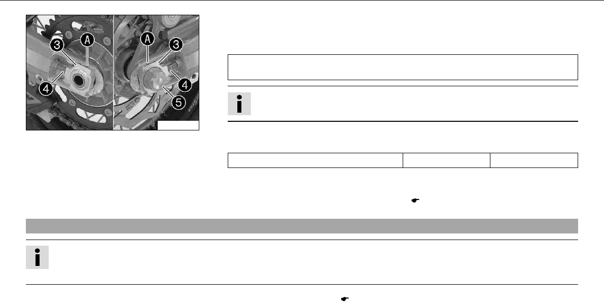
MAINTENANCE WORK ON CHASSIS AND ENGINE 97
100270-10
–Push the rear wheel forward as far as possible and place the chain on the rear sprocket.
–Mount the wheel spindle, chain adjuster and nut.
Specification
In order for the rear wheel to be correctly aligned, the markings on the left and right
chain adjusters must be in the same position relative to the reference marks.
Info
Fit the chain left and right adjustersin similar positions.
–Tighten nut.
Specification
Nut, rear wheel spindle M25x1.5 90Nm (66.4lbfft)
–Operate the foot brake lever repeatedly until the brake linings lie on the brake disc and
there is a tight spot.
–Remove the motorcycle from the work stand. ( P. 56)
9.44Checking the rear hub rubber dampersx
Info
The engine power is transmitted from the rear sprocket to the rear wheel via 6 rubber dampers. They eventually wear out during
operation. If the rubber dampers are not changed in time, the rear sprocket carrier and the rear hub will be damaged.
–Remove the rear wheel.x( P. 95)
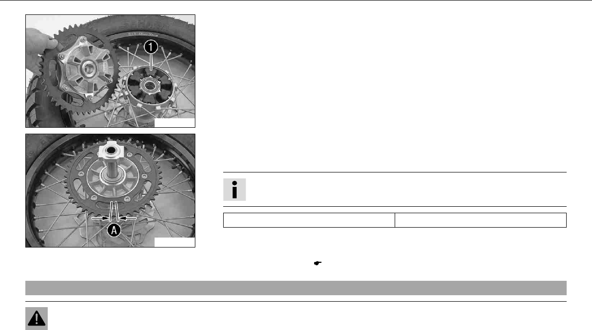
MAINTENANCE WORK ON CHASSIS AND ENGINE 98
100271-10
–Check rubber dampersof the rear hub for damage and wear.
» If the rubber dampers of the rear hub are damaged or worn:
–Change all rubber dampers in the rear hub.
100272-10
–Lay the read wheel on a workbench with the rear sprocket facing upwards and insert the
wheel spindle in the hub.
–To check the play, hold the rear wheel tight and try to rotate the rear sprocket.
Info
Measure the play on the outside of the rear sprocket.
Play in rubber dampers, rear wheel ≤5mm (≤0.2in)
» If the playis more than the specified value:
–Change all rubber dampers in the rear hub.
–Fit the rear wheel.x( P. 96)
9.45Tire condition checking
Warning
Danger of accidents Uncontrollable handling behavior caused by a flat tire.
–For your own safety, have damaged tires changed immediately.
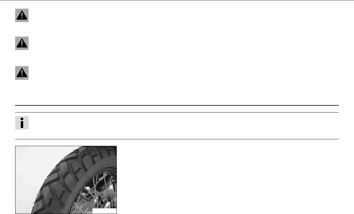
MAINTENANCE WORK ON CHASSIS AND ENGINE 99
Warning
Danger of crashing Impairment of riding behavior due to different tire tread patterns on front and rear wheels.
–The front and rear wheels must be fitted with tires with similar tread patterns to prevent loss of control over the vehicle.
Warning
Danger of accidents Uncontrollable handling behavior caused by non-approved tires/wheels.
–Use only tires/wheels approved by KTM with the corresponding speed index.
Warning
Danger of accidents Reduced road grip with new tires.
–New tires have a smooth roll surface and therefore cannot provide full road grip. The entire roll surface must be roughened in
the first 200 kilometers (124.3 miles) by moderate driving at alternating angles. The full grip is not reached until the vehicle
has been run in.
Info
The type, condition and air pressure of the tires all have an important impact on the riding behavior of the motorcycle.
Worn tires have a negative effect on riding behavior, especially on wet surfaces.
100273-01
–Check the front and rear tire for cuts, penetrations and other damage.
» If the tires exhibits cuts, penetrations or other damage:
–Change the tires.
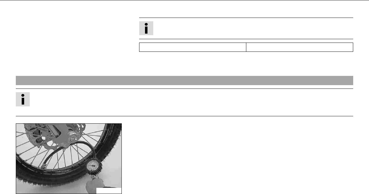
MAINTENANCE WORK ON CHASSIS AND ENGINE 100
–Check the depth of the tread.
Info
Note local national regulations concerning the minimum tread depth.
Minimum tread depth ≥2mm (≥0.08in)
» If the minimum tread depth is insufficient:
–Change the tires.
9.46Checking tire air pressure
Info
Low tire air pressure leads to abnormal wear and overheating of the tire.
Correct tire air pressure ensures optimal riding comfort and maximum tire service life.
100274-01
–Remove dust cap.
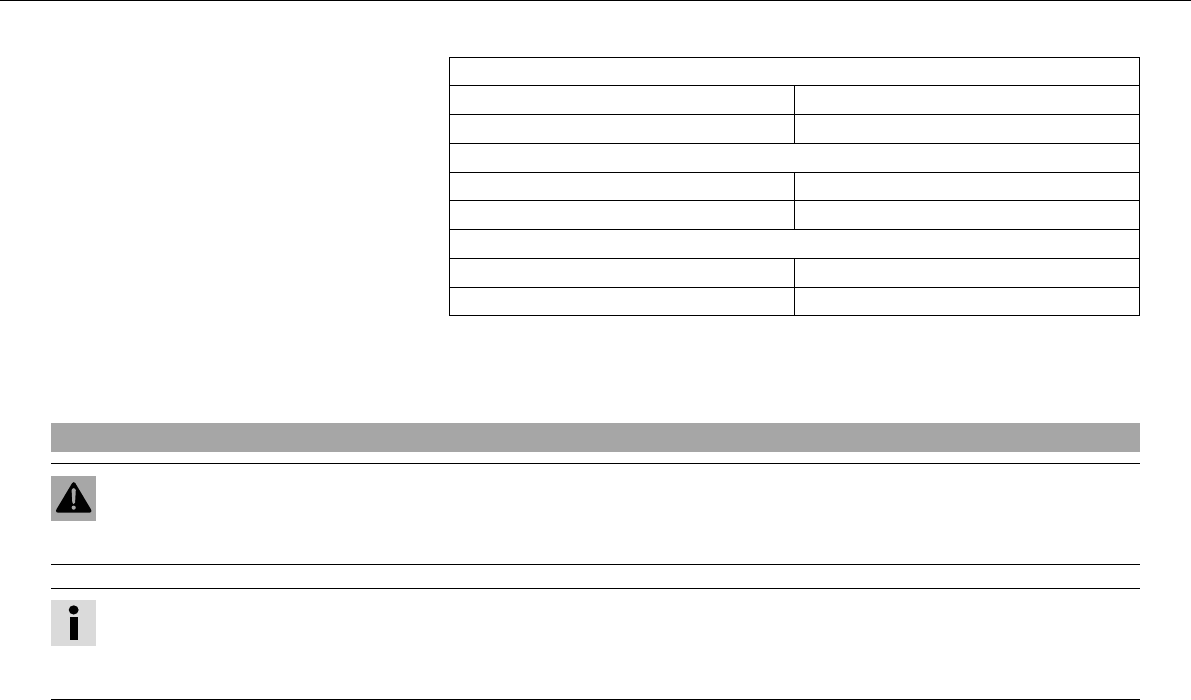
MAINTENANCE WORK ON CHASSIS AND ENGINE 101
–Check tire air pressure when tires are cold.
Tire air pressure, offroad, single rider
front 1.5bar (22psi)
Rear 1.5bar (22psi)
Tire air pressure, road, solo
front 1.8bar (26psi)
Rear 1.8bar (26psi)
Tire air pressure with passenger / fully loaded
front 2.0bar (29psi)
Rear 2.2bar (32psi)
» If the tire pressure does not meet specifications:
–Correct tire pressure.
–Mount dust cap.
9.47Checking spoke tension
Warning
Danger of accidents Unstable riding behavior due to loose spokes.
–If you ride with loose spokes, the spokes can break. Have the spoke tension corrected in an authorized KTM workshop.
Info
A loose spoke can cause wheel imbalance, which leads to more loose spokes in a short time.
If the spokes are too tight, they can break due to local overload.
Check the spoke tension regularly, especially on a new motorcycle.
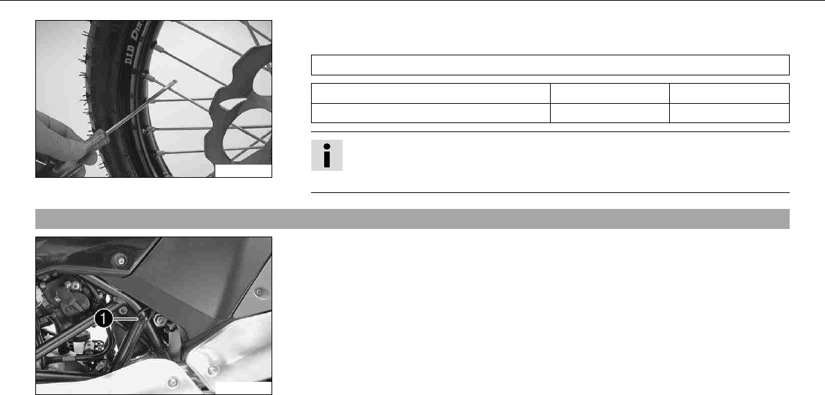
MAINTENANCE WORK ON CHASSIS AND ENGINE 102
100275-01
–To check spoke tension, tap each spoke with a screwdriver.
Specification
You should hear a high note.
Spoke nipple, front wheel M5 4Nm (3lbfft)
Spoke nipple, rear wheel M5 4Nm (3lbfft)
Info
If you hear different tone frequencies from different spokes, this is an indication
of different spoke tensions.
9.48Removing the seat
100230-10
–Pull on strapand raise the rear of the seat at the same time.
–Pull back the seat and lift it off.
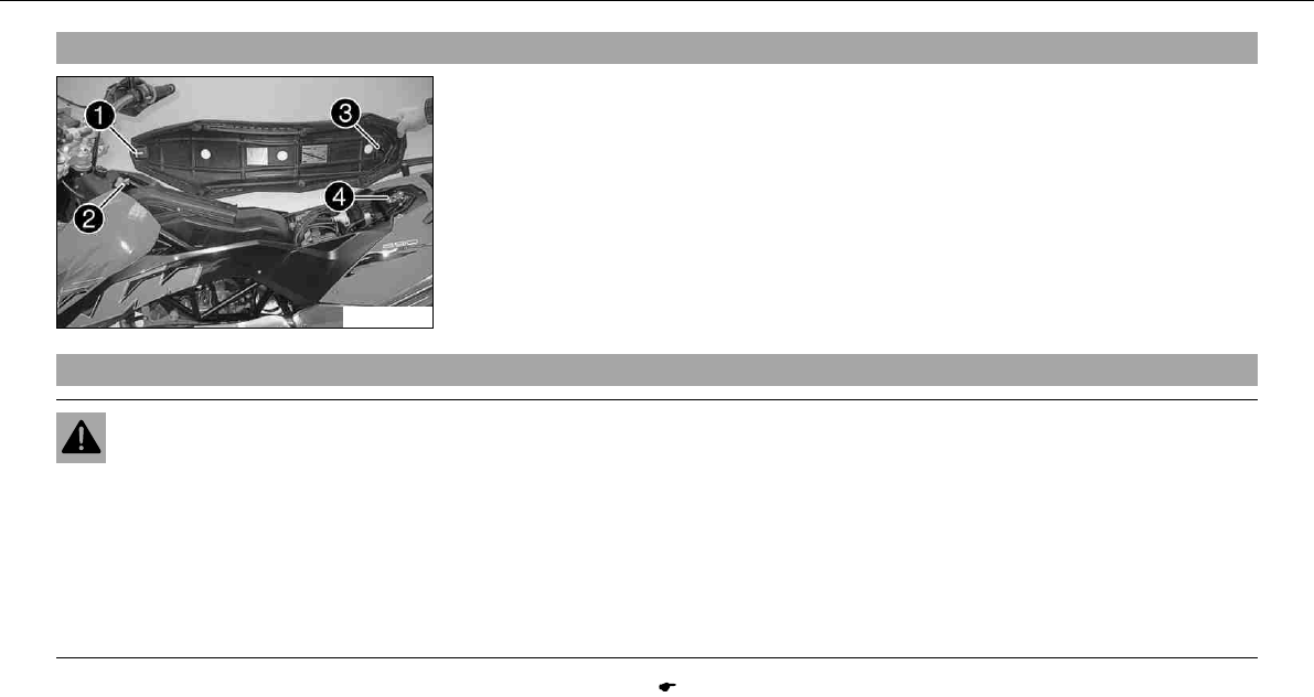
MAINTENANCE WORK ON CHASSIS AND ENGINE 103
9.49Mounting the seat
100276-10
–Hook slotof the seat onto screw, press the rear downward and at the same time
push it forward.
–Push locking pininto lock housingand push the back of the seat down until the
locking pin locks in place with an audible click.
–Finally, check that the seat is correctly mounted.
9.50Removing the batteryx
Warning
Risk of injury Battery acid and battery gases cause serious cauterization.
–Keep batteries out of the reach of children.
–Wear suitable protective clothing and goggles.
–Avoid contact with battery acid and battery gases.
–Keep the battery away from sparks or open fire. Charge only in well ventilated rooms.
–In the event of skin contact, rinse with large amounts of water. If battery acid gets in the eyes, rinse with water for at least 15
minutes and contact a doctor.
–Remove the seat. ( P. 102)
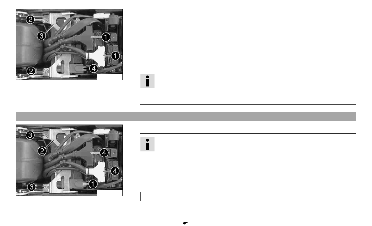
MAINTENANCE WORK ON CHASSIS AND ENGINE 104
100277-10
–Disconnect the negative (minus) cable of the battery.
–Pull off connectorin an upward direction.
–Remove screws.
–Pull retaining bracketof the battery forward and remove it.
–Take off the positive terminal cover.
–Disconnect the positive (plus) cable of the battery.
–Press the wiring harness to one side and pull the battery out of the battery rack.
Info
Never operate the motorcycle with a discharged battery or without a battery. In
both cases, electrical components can safety equipment can be damaged. The
vehicle is then no longer safe to ride.
9.51Installing the batteryx
100277-11
–Slide the battery into the battery rack.
Info
The battery terminals must be at the rear.
–Attach the positive cable and mount positive terminal cover.
–Position retaining bracket.
–Mount and tighten screws.
Specification
Remaining screws, chassis M6 10Nm (7.4lbfft)
–Plug in connector.
–Attach the minus cable.
–Mount the seat. ( P. 103)
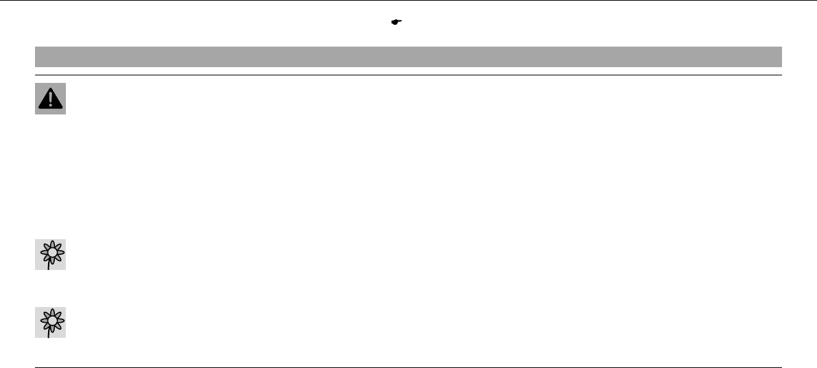
MAINTENANCE WORK ON CHASSIS AND ENGINE 105
–Set the clock. ( P. 29)
9.52Recharging the batteryx
Warning
Risk of injury Battery acid and battery gases cause serious cauterization.
–Keep batteries out of the reach of children.
–Wear suitable protective clothing and goggles.
–Avoid contact with battery acid and battery gases.
–Keep the battery away from sparks or open fire. Charge only in well ventilated rooms.
–In the event of skin contact, rinse with large amounts of water. If battery acid gets in the eyes, rinse with water for at least 15
minutes and contact a doctor.
Warning
Environmental hazard Components and battery acid are a danger to the environment.
–Do not dispose of batteries in normal household waste. Take defective or used batteries to a battery recycling operator.
Warning
Environmental hazard Problem materials cause environmental damage.
–Dispose of oil, grease, filters, fuel, cleaning substances, brake fluid, batteries, etc. according to regulations.
MAINTENANCE WORK ON CHASSIS AND ENGINE 106
Info
Even if there is no load on the battery, it loses power every day.
The charge state and the type of charge are very important for the service life of the battery.
Fast recharging with a high charge current shortens the battery's service life.
If the charge current, the charge voltage and the charge time are exceeded, electrolyte escapes through the breathing holes. The
battery capacity is then reduced.
If the battery becomes discharged from starting, it must be recharged immediately.
If the battery rests for an extended time in a discharged state, it becomes over-discharged and sulfated, which will result in its
destruction.
The battery is maintenance-free, i.e., the acid level does not have to be checked.
–Switch off all power-consuming components and switch off the engine.
–Remove the battery.x( P. 103)
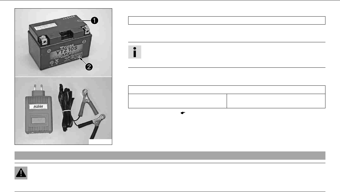
MAINTENANCE WORK ON CHASSIS AND ENGINE 107
100151-10
–Connect the battery charger to the battery. Switch on the battery charger.
Battery charger(58429074000)
You can also use the battery charger to test rest potential and start potential of the bat-
tery, and to test the generator. With this device, you cannot overcharge the battery.
Info
Never remove the lid.
Charge the battery according to the instructionson the battery casing.
–After charging, switch off and disconnect the battery charger.
Specification
The charge current, charge voltage and charge time must not be exceeded.
Charge the battery regularly when the
motorcycle is not in use.
3months
–Install the battery.x( P. 104)
9.53Changing the main fuse
Warning
Fire hazard The electrical system can be overloaded by the use of incorrect fuses.
–Use only fuses with the prescribed amperage. Never by-pass or repair fuses.
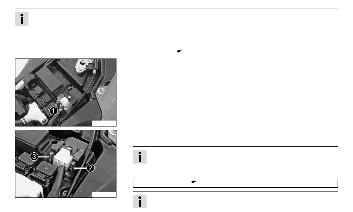
MAINTENANCE WORK ON CHASSIS AND ENGINE 108
Info
The main fuse protects all power-consuming components of the vehicle. It is located in the housing of the electric starter relay next
to the battery.
–Switch off all power-consuming components and switch off the engine.
–Remove the seat. ( P. 102)
600604-10
–Remove protection covers.
600605-10
–Remove a defective main fusewith a needle nose plier.
–Check parts for damage and wear. Replace damaged or worn parts.
Info
A reserve fuseis located in the starter relay.
–Fit a new main fuse.
Fuse(58011109130) ( P. 158)
Info
If the new fuse burns out, contact an authorized KTM workshop.
–Check the functioning of the electrical equipment.
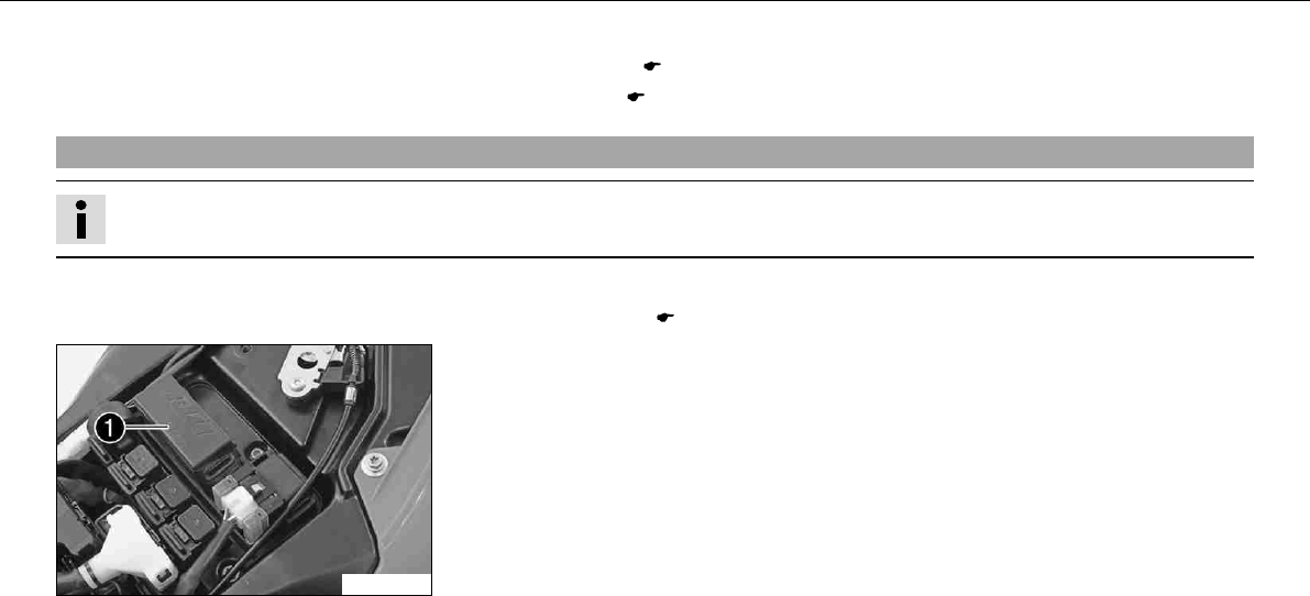
MAINTENANCE WORK ON CHASSIS AND ENGINE 109
–Attach the protection covers.
–Mount the seat. ( P. 103)
–Set the clock. ( P. 29)
9.54Changing fuses of individual power consumers
Info
The fuse box containing the fuses of individual power consumers is located under the seat.
–Switch off all power-consuming components and switch off the engine.
–Remove the seat. ( P. 102)
600604-11
–Open the fuse box cover.
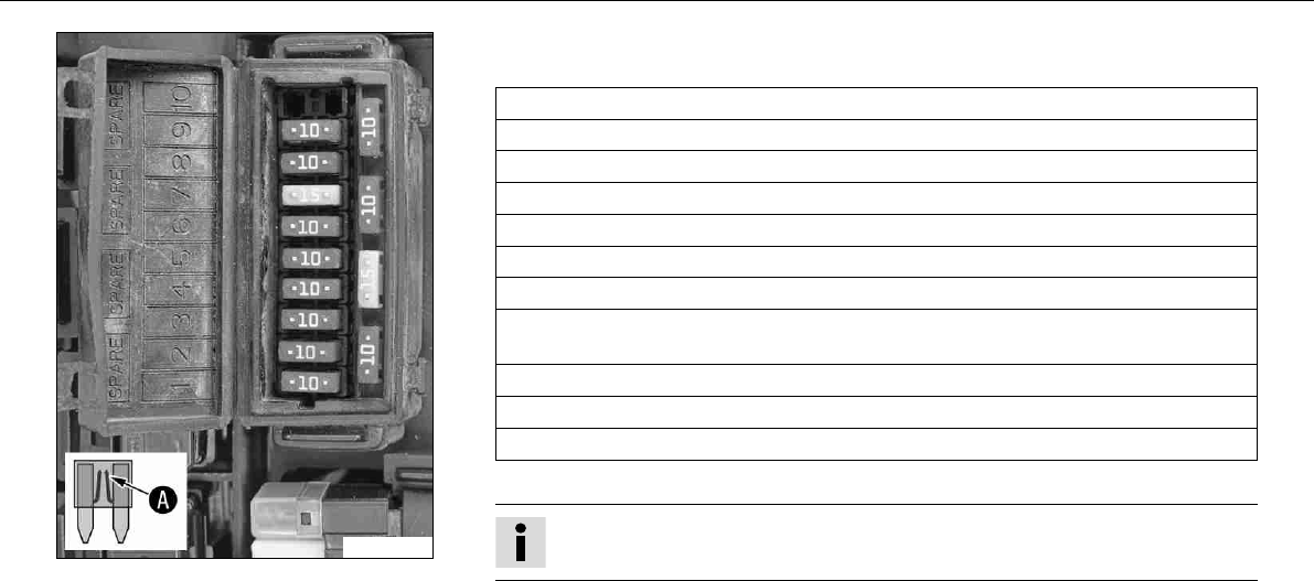
MAINTENANCE WORK ON CHASSIS AND ENGINE 110
600606-10
–Remove defective fuse.
Specification
Fuse1- 10A - ignition, combination instrument, alarm system (optional)
Fuse2- 10A - clock, ignition (EFI control unit)
Fuse3- 10A - throttle valve control unit
Fuse4- 10A - fuel pump
Fuse5- 10A - radiator fan
Fuse6- 10A - horn, brake light, flasher light, alarm system (optional)
Fuse7- 15A - high beam, low beam, parking light, tail light, license plate lamp
Fuse8- 10A - for supplementary equipment (accessories connected with ignition
switch)
Fuse9- 10A - for supplementary equipment (standard accessories)
Fuse10 - not used
FuseSPARE - 10A/15A - spare fuses
–Check parts for damage and wear. Replace damaged or worn parts.
Info
A defective fuse is shown by a burned-out fuse wire.
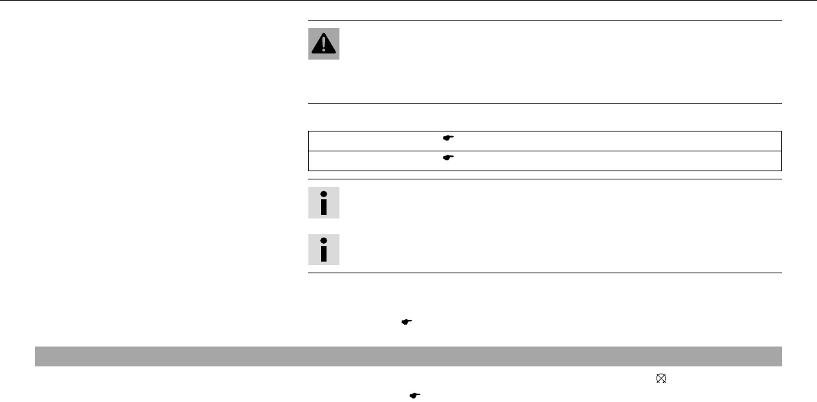
MAINTENANCE WORK ON CHASSIS AND ENGINE 111
Warning
Fire hazard The electrical system can be overloaded by the use of incorrect
fuses.
–Use only fuses with the prescribed amperage. Never by-pass or repair fuses.
–Use spare fuses with the correct rating only.
Fuse(75011088010) ( P. 158)
Fuse(75011088015) ( P. 158)
Info
If the new fuse burns out, contact an authorized KTM workshop.
Tip
Replace the spare fuse in the fuse box so that it will be available if needed.
–Check the functioning of the power consumer.
–Close the fuse box cover.
–Mount the seat. ( P. 103)
9.55Adjusting the engine characteristic
–Switch off the ignition by turning the ignition key in the position.
–Remove the seat. ( P. 102)
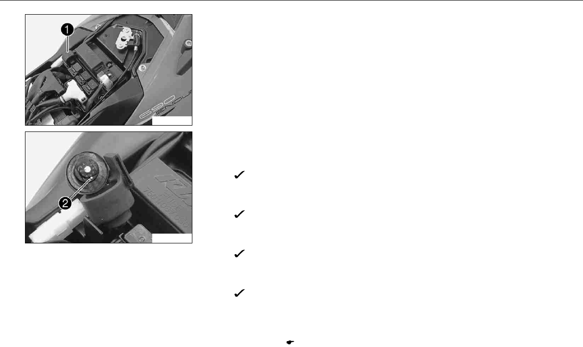
MAINTENANCE WORK ON CHASSIS AND ENGINE 112
100237-10
–Pull the Map‑Selectswitch and holderupward off of the retaining bracket.
–Pull the Map‑Selectswitch out of the holder.
100238-10
–Turn the adjusting wheel until the desired digit is next to marking.
Set the Map‑Selectswitch to Soft.
–Set the adjusting wheel to position1.
Soft –reduced homologated peak performance for better driveability.
Set the Map‑Selectswitch to Advanced.
–Set the adjusting wheel to position2.
Advanced –homologated performance with extremely direct responsiveness.
Set the Map‑Selectswitch to Standard.
–Set the adjusting wheel to position3,4,5,6,7,8or 9.
Standard –homologated performance with balanced responsiveness.
Set the Map‑Selectswitch to poor fuel quality.
–Set the adjusting wheel to position0.
Poor fuel quality –homologated performance is reduced in accordance with the
fuel quality, use for no more than 1 tank of fuel
–Position the Map‑Selectswitch in the holder.
–Slide the Map‑Selectswitch with the holder downward onto the retaining bracket.
–Mount the seat. ( P. 103)
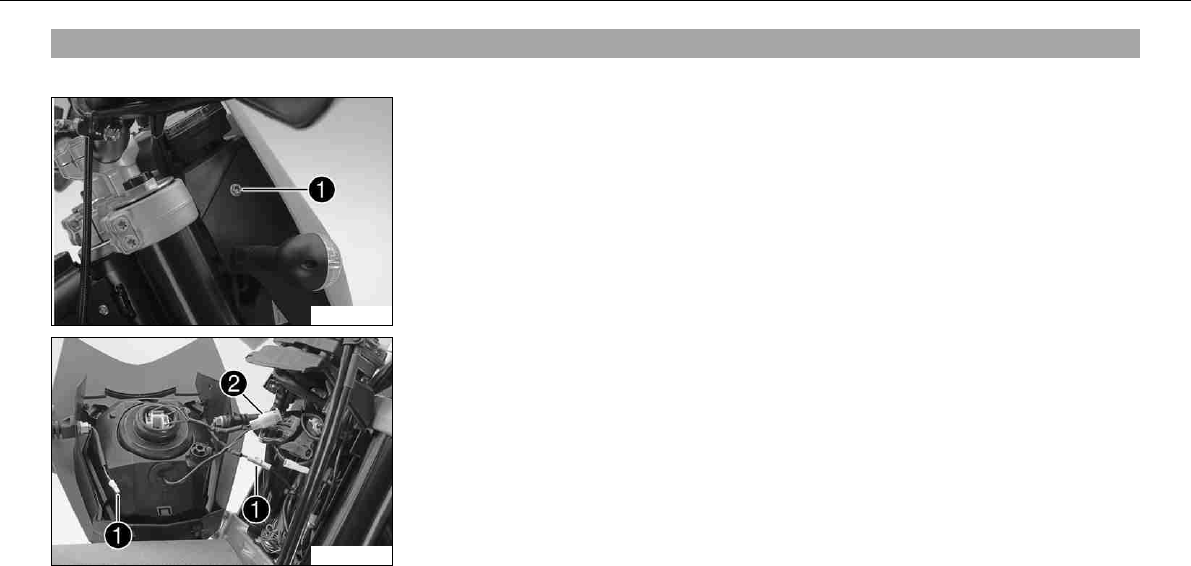
MAINTENANCE WORK ON CHASSIS AND ENGINE 113
9.56Removing headlight mask with headlight
–Switch off all power-consuming components and switch off the engine.
600607-10
–Protect the fender against damage by covering it with a cloth.
–Remove the screwson the left and right.
–Tilt the headlight mask forward and lift it off.
100294-10
–Disconnect the connectors of flasher lightsand headlight.
–Place the headlight mask to one side.
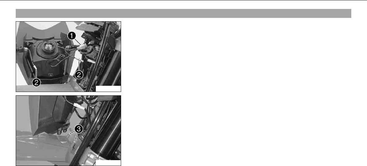
MAINTENANCE WORK ON CHASSIS AND ENGINE 114
9.57Refitting the headlight mask with the headlight
100294-11
–Connect the connectors of headlightand flasher lights.
–Check lighting function.
100295-10
–Remove the cloth from the fender, attach the headlight mask to pointson the fender
and swing it up to the steering head.
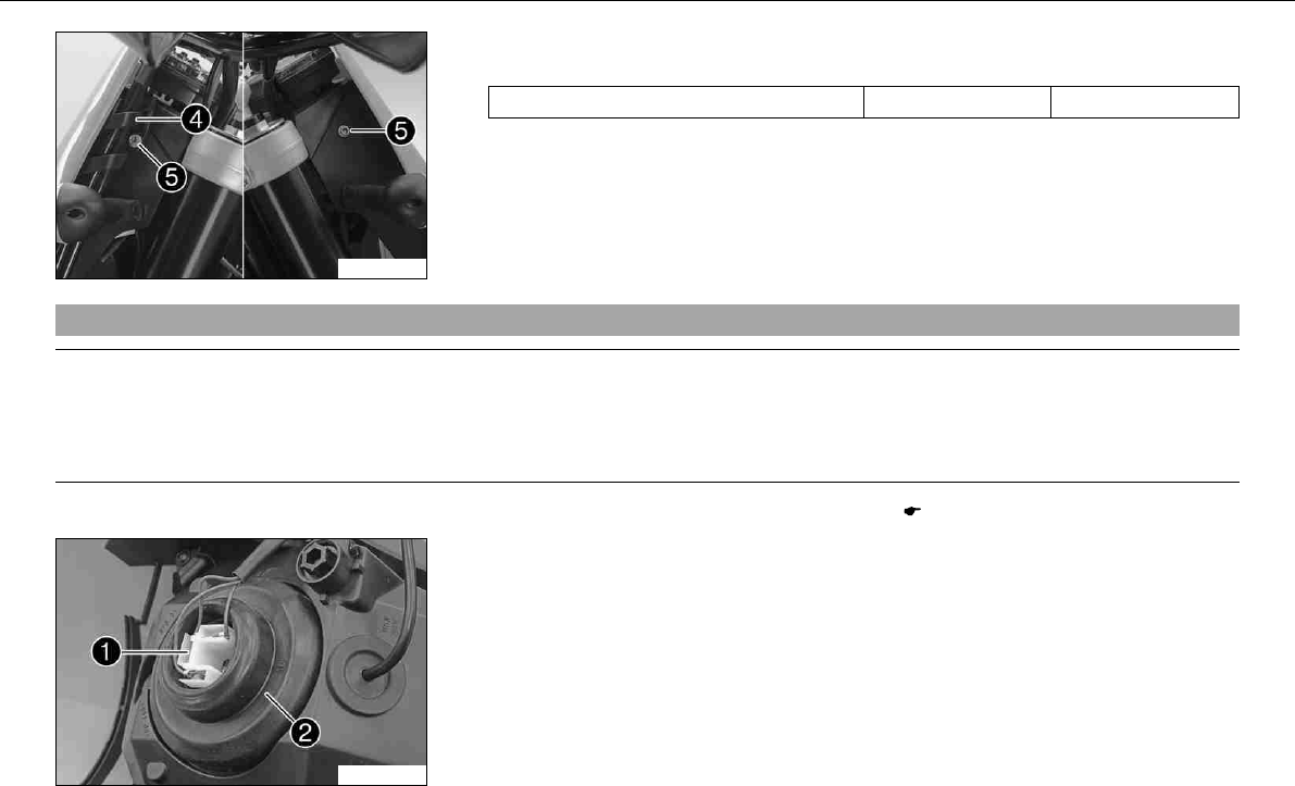
MAINTENANCE WORK ON CHASSIS AND ENGINE 115
100296-10
–Position brake-hose guide. Mount and tighten screws.
Specification
Remaining screws, chassis M6 10Nm (7.4lbfft)
9.58Changing the headlight bulb
Note
Damage to reflector Keep the glass of the bulb free of grease.
–Clean the glass bulb with a clean cloth before mounting. Any grease on the glass will evaporate by the heat and be deposited on the
reflector.
–Remove the headlight mask with the headlight. ( P. 113)
600610-10
–Pull off connector.
–Take off rubber capof the headlight bulb.
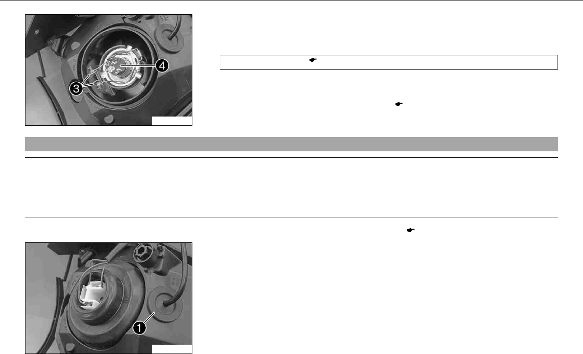
MAINTENANCE WORK ON CHASSIS AND ENGINE 116
600611-10
–Detach spring bar.
–Remove headlight bulb.
–Insert a new headlight bulb into the headlight housing.
Headlight(H4/P43t) ( P. 158)
–Fit the headlight bulb in the headlight using the spring bar.
–Replace the rubber cap. Attach the connector.
–Refit the headlight mask with the headlight. ( P. 114)
9.59Changing the parking light bulb
Note
Damage to reflector Keep the glass of the bulb free of grease.
–Clean the glass bulb with a clean cloth before mounting. Any grease on the glass will evaporate by the heat and be deposited on the
reflector.
–Remove the headlight mask with the headlight. ( P. 113)
600610-12
–Remove rubber cap.
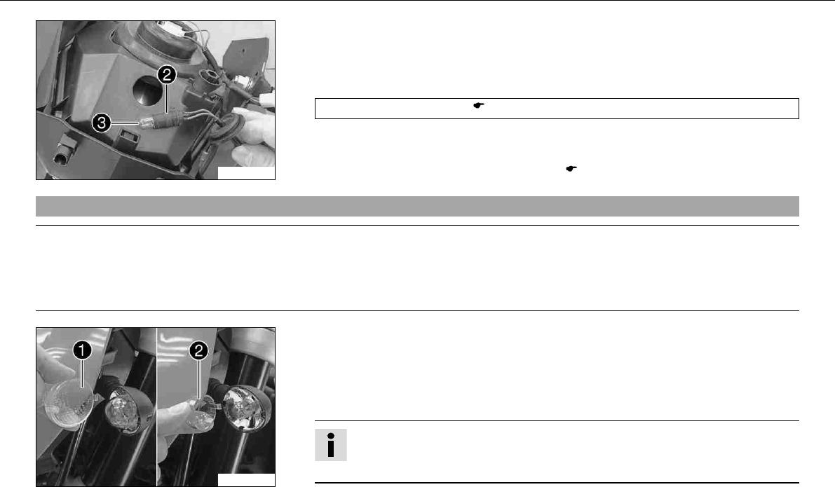
MAINTENANCE WORK ON CHASSIS AND ENGINE 117
600612-10
–Pull bulb socketout of the reflector.
–Pull parking light bulbout of the bulb socket.
–Check parts for damage and wear. Replace damaged or worn parts.
–Insert a new parking light bulb into the bulb socket.
Parking light(W2,1x9,5d) ( P. 158)
–Insert the bulb socket into the reflector.
–Insert the rubber cap.
–Refit the headlight mask with the headlight. ( P. 114)
9.60Changing the flasher bulb
Note
Damage to reflector Keep the glass of the bulb free of grease.
–Clean the glass bulb with a clean cloth before mounting. Any grease on the glass will evaporate by the heat and be deposited on the
reflector.
100301-10
–Remove the screw on the rear of the flasher housing.
–Carefully swing the diffuserforwards and remove it.
–Lightly pinch the orange capat the holding points and remove it.
–Press the flasher bulb carefully into the holder, turn it about 30° counterclockwise and
remove it from the holder.
Info
Do not touch the reflector with your fingers and try to avoid contact with oil or
grease.
–Check parts for damage and wear. Replace damaged or worn parts.
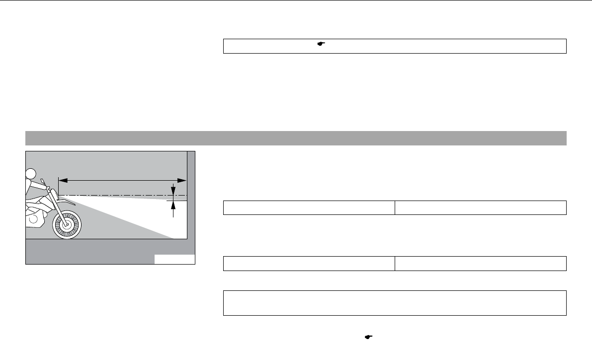
0
0
BB
0
0
AA
MAINTENANCE WORK ON CHASSIS AND ENGINE 118
–Press the new flasher bulb carefully into the holder and turn it clockwise as far as it will
go.
Flasher light(BA15s) ( P. 158)
–Mount the orange cap.
–Position the diffuser.
–Insert the screw and turn it first counterclockwise until you feel it click into the thread.
Tighten the screw.
–Check the flasher function.
9.61Checking headlamp setting
400408-10
–On a light-colored wall with a horizontal area in front of it, make a mark as high as the
center of the low beam headlight.
–Make another mark at a distance ofunder the first mark.
Specification
Distance5cm (2in)
–Stand the motorcycle at a distance ofin front of the wall and switch on the low
beam.
Specification
Distance5m (16ft)
–Check the headlamp setting.
The boundary between light and dark must be exactly on the lower mark for a motor-
cycle with driver.
» If the boundary between light and dark does not meet specifications:
–Adjust the headlight range. ( P. 119)
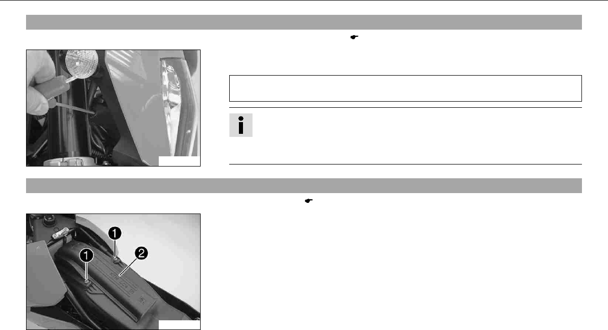
MAINTENANCE WORK ON CHASSIS AND ENGINE 119
9.62Adjusting the headlight range
–Check the headlamp setting. ( P. 118)
600613-01
–Use a screwdriver (see illustration) to adjust the headlight range.
Specification
The boundary between light and dark must be exactly on the lower mark for a motor-
cycle with a rider (mark is applied under: Checking headlight adjustment).
Info
Turn clockwise to increase the light range, turn counterclockwise to reduce the
light range.
If you have a payload, you may have to correct the headlight range.
9.63Removing the air filterx
–Remove the seat. ( P. 102)
100285-10
–Remove screws. Remove filter box top.
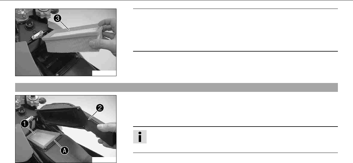
MAINTENANCE WORK ON CHASSIS AND ENGINE 120
100286-10
Note
Engine failure Unfiltered intake air has a negative effect on the service life of the
engine.
–Never ride the vehicle without an air filter since dust and dirt can get into the
engine and result in increased wear.
–Remove air filter.
9.64Installing the air filterx
100287-10
–Check parts for damage and wear. Change damaged or worn parts. Change the air filter
if it is dirty or wet.
–Clean the air filter box.
–Mount air filter.
Info
The air filter must be in contact with the air filter box along the entire sealing
surface.
–Attach filter box topat the front of the air filter box and swing it down.
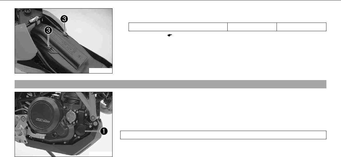
MAINTENANCE WORK ON CHASSIS AND ENGINE 121
100285-11
–Mount and tighten screws.
Specification
Remaining screws, chassis M6 10Nm (7.4lbfft)
–Mount the seat. ( P. 103)
9.65Cooling system
600614-10
The water pumpin the engine forces the coolant to flow.
The pressure resulting from the warming of the cooling system is regulated by a valve in
the radiator cap. Heat expansion causes excess coolant to flow into the compensating
tank. If the temperature falls, the excess coolant is sucked back into the cooling system.
The specified coolant temperature is therefore permissible without danger of function prob-
lems.
125°C (257°F)
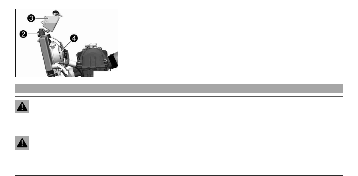
MAINTENANCE WORK ON CHASSIS AND ENGINE 122
400407-10
The coolant is cooled by the air stream and a radiator fan, which is controlled by a ther-
moswitch.
The lower the speed, the less the cooling effect. Dirty cooling fins also reduce the cooling
effect.
9.66Checking the antifreeze and coolant level
Warning
Danger of scalding The coolant gets very hot when the motorcycle is driven and is under high pressure.
–Do not open the radiator, radiator hoses or other cooling system components when the engine is hot. Allow the engine and cool-
ing system to cool down. If you scald yourself, hold the affected area under cold water immediately.
Warning
Danger of poisoning Coolants are poisonous and a health hazard.
–Avoid contact between coolants and skin, eyes and clothing. If fuel gets into your eyes, rinse immediately with water and con-
tact a doctor. Wash affected skin areas immediately with soap and water. If coolant is swallowed, contact a doctor immediately.
Change clothes that have come into contact with coolants. Keep coolants out of the reach of children.
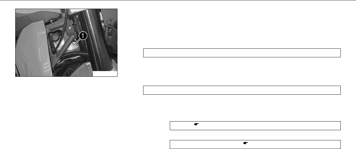
MAINTENANCE WORK ON CHASSIS AND ENGINE 123
100283-10
Condition
Engine is cold.
–Stand the motorcycle on its side stand on a horizontal surface.
–Remove the cap of the compensating tank.
–Check antifreeze of coolant.
−25… −45°C (−13… −49°F)
» If the antifreeze of the cooling liquid does not meet specifications:
–Correct antifreeze of coolant.
–Check the coolant level in the compensating tank.
The coolant level must be within the range shown in the figure.
» If the level of the cooling liquid does not meet specifications:
–Correct the coolant level.
Alternative 1
Coolant ( P. 166)
Alternative 2
Coolant (mixed ready to use) ( P. 166)
–Mount the cap of the compensating tank.
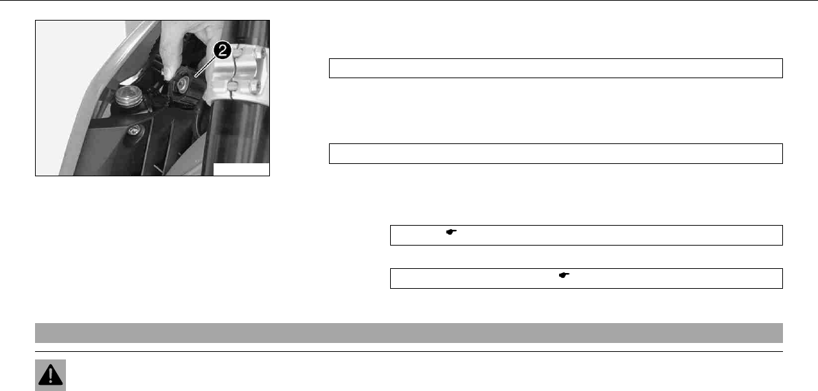
MAINTENANCE WORK ON CHASSIS AND ENGINE 124
100284-10
–Screw off the radiator cap.
–Check antifreeze of coolant.
−25… −45°C (−13… −49°F)
» If the antifreeze of the cooling liquid does not meet specifications:
–Correct antifreeze of coolant.
–Check the coolant level in the radiator.
The radiator must be completely full.
» If the level of the cooling liquid does not meet specifications:
–Correct the coolant level and find out the cause of the loss.
Alternative 1
Coolant ( P. 166)
Alternative 2
Coolant (mixed ready to use) ( P. 166)
–Refit the radiator cap.
9.67Checking the coolant level
Warning
Danger of scalding The coolant gets very hot when the motorcycle is driven and is under high pressure.
–Do not open the radiator, radiator hoses or other cooling system components when the engine is hot. Allow the engine and cool-
ing system to cool down. If you scald yourself, hold the affected area under cold water immediately.
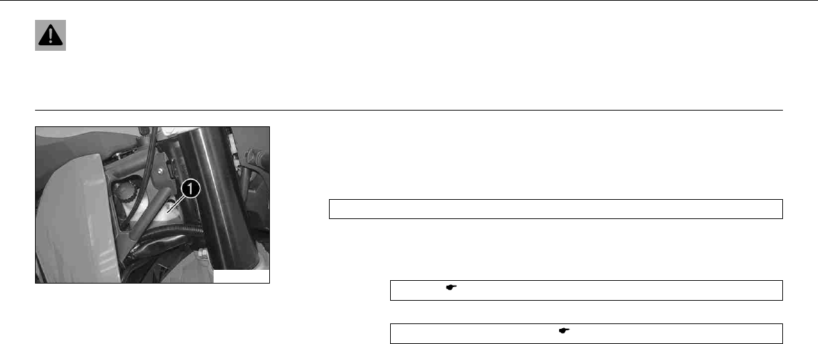
MAINTENANCE WORK ON CHASSIS AND ENGINE 125
Warning
Danger of poisoning Coolants are poisonous and a health hazard.
–Avoid contact between coolants and skin, eyes and clothing. If fuel gets into your eyes, rinse immediately with water and con-
tact a doctor. Wash affected skin areas immediately with soap and water. If coolant is swallowed, contact a doctor immediately.
Change clothes that have come into contact with coolants. Keep coolants out of the reach of children.
100283-10
Condition
Engine is cold.
–Stand the motorcycle on its side stand on a horizontal surface.
–Check the coolant level in the compensating tank.
The coolant level must be within the range shown in the figure.
» If the level of the cooling liquid does not meet specifications:
–Correct the coolant level.
Alternative 1
Coolant ( P. 166)
Alternative 2
Coolant (mixed ready to use) ( P. 166)
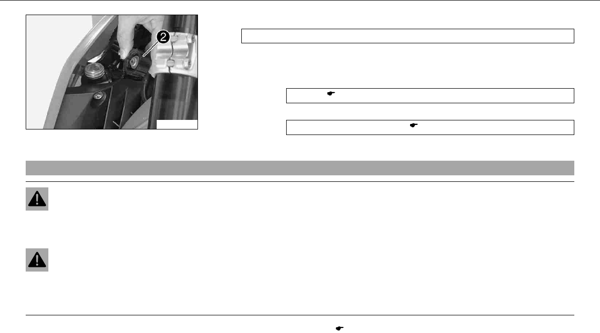
MAINTENANCE WORK ON CHASSIS AND ENGINE 126
100284-10
–Screw off the radiator capand check the coolant level in the radiator.
The radiator must be completely full.
» If the level of the cooling liquid does not meet specifications:
–Correct the coolant level and find out the cause of the loss.
Alternative 1
Coolant ( P. 166)
Alternative 2
Coolant (mixed ready to use) ( P. 166)
–Refit the radiator cap.
9.68Draining coolantx
Warning
Danger of scalding The coolant gets very hot when the motorcycle is driven and is under high pressure.
–Do not open the radiator, radiator hoses or other cooling system components when the engine is hot. Allow the engine and cool-
ing system to cool down. If you scald yourself, hold the affected area under cold water immediately.
Warning
Danger of poisoning Coolants are poisonous and a health hazard.
–Avoid contact between coolants and skin, eyes and clothing. If fuel gets into your eyes, rinse immediately with water and con-
tact a doctor. Wash affected skin areas immediately with soap and water. If coolant is swallowed, contact a doctor immediately.
Change clothes that have come into contact with coolants. Keep coolants out of the reach of children.
–Remove the engine guard. ( P. 132)
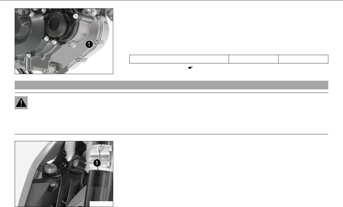
MAINTENANCE WORK ON CHASSIS AND ENGINE 127
600616-10
–Stand the vehicle upright.
–Place a suitable container under the engine.
–Remove screw. Remove the radiator cap.
–Completely drain the coolant.
–Fit screwwith a new seal and tighten it.
Specification
Plug, drain hole of water pump M10x1 15Nm (11.1lbfft)
–Install the engine guard. ( P. 132)
9.69Filling the cooling systemx
Warning
Danger of poisoning Coolants are poisonous and a health hazard.
–Avoid contact between coolants and skin, eyes and clothing. If fuel gets into your eyes, rinse immediately with water and con-
tact a doctor. Wash affected skin areas immediately with soap and water. If coolant is swallowed, contact a doctor immediately.
Change clothes that have come into contact with coolants. Keep coolants out of the reach of children.
600618-10
–Stand the motorcycle on its side stand on a horizontal surface.
–Remove radiator cap.
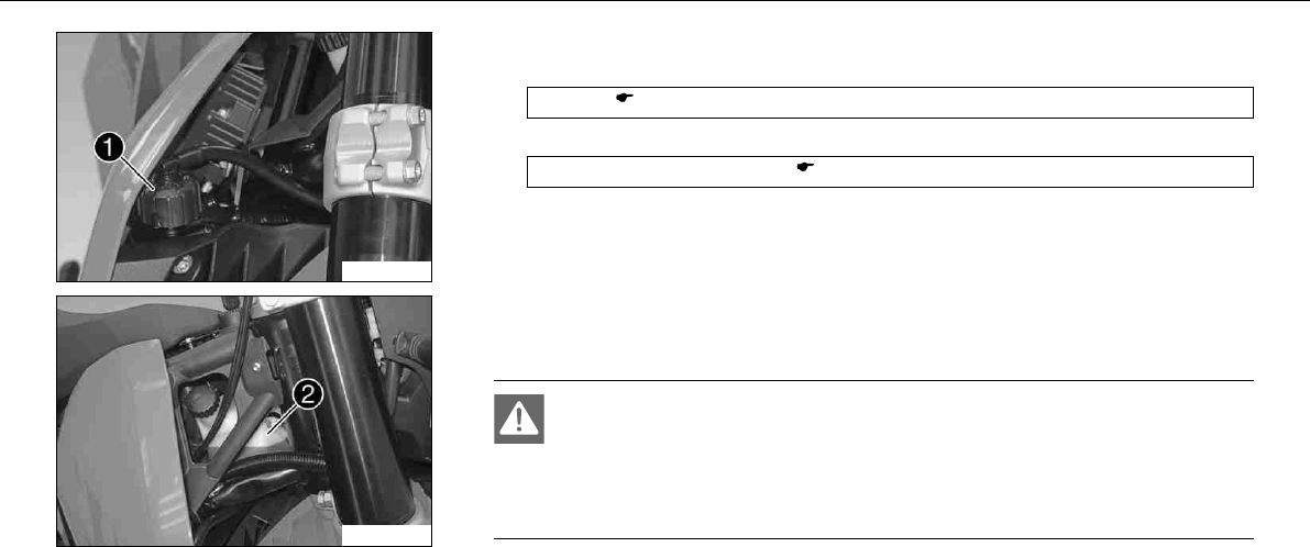
MAINTENANCE WORK ON CHASSIS AND ENGINE 128
600619-10
–Refill the coolant.
Alternative 1
Coolant ( P. 166)
Alternative 2
Coolant (mixed ready to use) ( P. 166)
–Fill the radiator completely with coolant. Mount radiator cap.
100283-11
–Remove the cap from compensating tankand add coolant to the level shown in the
figure.
–Mount the cap of the compensating tank.
Danger
Danger of poisoning Exhaust gases are poisonous and can result in
unconsciousness and/or death.
–When running the engine, always make sure there is sufficient ventilation,
and do not start or run the engine in a closed space.
–Start the engine and run it until the 5th bar of the temperature indicator lights up.
–Switch off the engine and allow it to cool down.
–After the engine has cooled down, check the coolant level in the radiator and in the
compensating tank again and add more coolant if necessary.
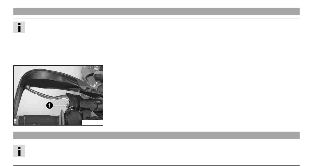
MAINTENANCE WORK ON CHASSIS AND ENGINE 129
9.70Adjusting basic position of clutch lever
Info
Turn the adjusting screw clockwise to increase the distance between the clutch lever and the handlebar.
Turn the adjusting screw counterclockwise to decrease the distance between the clutch lever and the handlebar.
The range of adjustment is limited.
Turn the adjusting screw by hand only, and do not apply any force.
Do not make any adjustments while riding!
100282-10
–Adjust the basic setting of the clutch lever to your hand size by turning adjusting
screw.
9.71Checking/correcting fluid level of hydraulic clutch
Info
The fluid level rises with increasing wear of the clutch lining disc.
Do not use brake fluid.
–Move the clutch fluid reservoir mounted on the handlebar to a horizontal position.
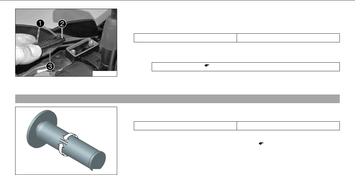
MAINTENANCE WORK ON CHASSIS AND ENGINE 130
100281-10
–Remove screws.
–Remove the coverwith membrane.
–Check the fluid level.
Fluid level under top level of container. 4mm (0.16in)
» If the fluid level does not meet specifications:
–Correct the fluid level of the hydraulic clutch.
Hydraulic fluid (15) ( P. 167)
–Check parts for damage and wear. Replace damaged or worn parts.
–Position the cover with the membrane. Mount and tighten screws.
9.72Checking play in gas Bowden cable
400192-10
–Move the handlebar to the straight-ahead position. Move the throttle grip backwards
and forwards to ascertain the play in the gas Bowden cable.
Play in gas Bowden cable 3… 5mm (0.12… 0.2in)
» If the gas Bowden cable play does not meet specifications:
–Adjust the play in the gas Bowden cable.x( P. 131)
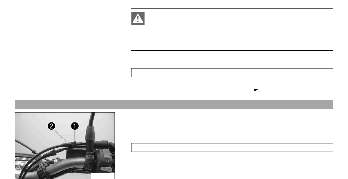
MAINTENANCE WORK ON CHASSIS AND ENGINE 131
Danger
Danger of poisoning Exhaust gases are poisonous and can result in
unconsciousness and/or death.
–When running the engine, always make sure there is sufficient ventilation,
and do not start or run the engine in a closed space.
–Start the engine and let it run idle. Move the handlebar to and fro over the entire steer-
ing range.
The idle speed must not change.
» If the idle speed changes:
–Adjust the play in the gas Bowden cable.x( P. 131)
9.73Adjusting play in gas Bowden cablex
100280-10
–Move the handlebar to the straight-ahead position.
–Loosen the lock nut.
–Adjust the play in the gas Bowden cable by turning the adjusting screw.
Specification
Play in gas Bowden cable 3… 5mm (0.12… 0.2in)
–Tighten the lock nut.
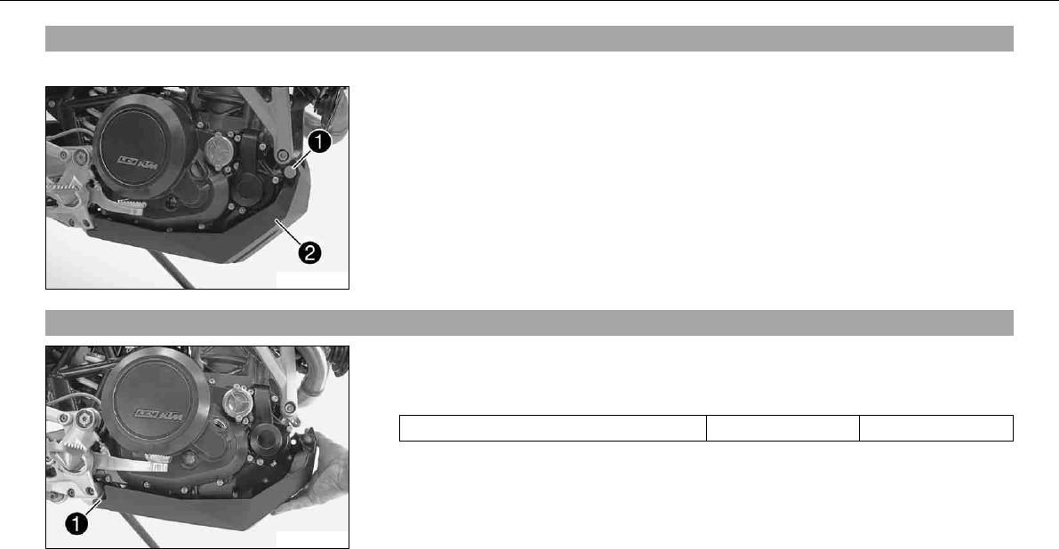
MAINTENANCE WORK ON CHASSIS AND ENGINE 132
9.74Removing the engine guard
–Stand the motorcycle on its side stand on a horizontal surface.
100198-10
–Remove screwson the left and right.
–Pull the engine guard forward out of the holders and set it down.
9.75Installing the engine guard
100199-10
–Slide the engine guard into holdersat the rear.
–Position the engine guard. Mount and tighten screws.
Specification
Remaining screws, chassis M6 10Nm (7.4lbfft)
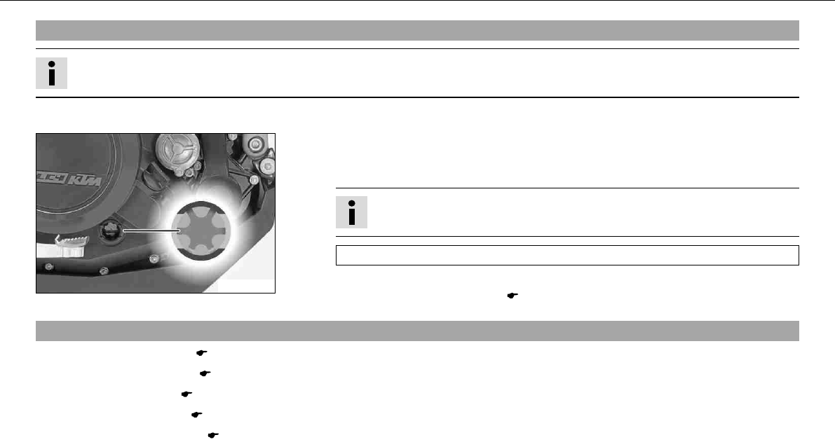
MAINTENANCE WORK ON CHASSIS AND ENGINE 133
9.76Checking engine oil level
Info
The engine oil level must be checked when the engine is at operating temperature.
–Stand the motorcycle upright on a horizontal surface.
100210-10
Condition
The engine is at operating temperature.
–Check the engine oil level.
Info
After switching off the engine, wait for one minute and then check.
The engine oil must be between the lower and upper edge of the oil level viewer.
» If the engine oil level is not at the specified level:
–Top up the engine oil. ( P. 140)
9.77Changing engine oil and oil filter, cleaning oil screensx
–Drain the engine oil.x( P. 134)
–Remove the oil filter.x( P. 135)
–Clean oil screens.x( P. 137)
–Mount the oil filter.x( P. 137)
–Fill up with engine oil.x( P. 139)
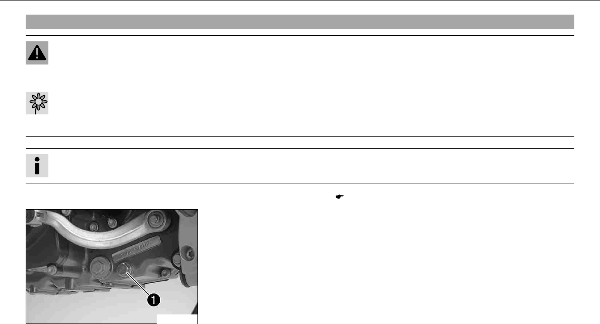
MAINTENANCE WORK ON CHASSIS AND ENGINE 134
9.78Draining engine oilx
Warning
Danger of scalding Engine oil and gear oil get very hot when the motocycle is driven.
–Wear suitable protective clothing and gloves. If you scald yourself, hold the affected area under cold water immediately.
Warning
Environmental hazard Problem materials cause environmental damage.
–Dispose of oil, grease, filters, fuel, cleaning substances, brake fluid, batteries, etc. according to regulations.
Info
Drain the engine oil only when the engine is warm.
–Remove the engine guard. ( P. 132)
100200-10
–Place a suitable container under the engine.
–Remove the oil drain plugwith the magnet and seal ring.
–Completely drain the engine oil.
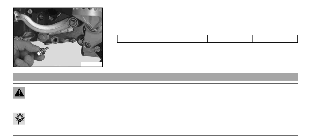
MAINTENANCE WORK ON CHASSIS AND ENGINE 135
100201-01
–Thoroughly clean the oil drain plug with a magnet.
–Check parts for damage and wear. Replace damaged or worn parts.
–Refit the oil drain plugwith the magnet and seal ring and tighten it.
Specification
Oil drain plug with magnet M12x1,5 20Nm (14.8lbfft)
9.79Removing the oil filterx
Warning
Danger of scalding Engine oil and gear oil get very hot when the motocycle is driven.
–Wear suitable protective clothing and gloves. If you scald yourself, hold the affected area under cold water immediately.
Warning
Environmental hazard Problem materials cause environmental damage.
–Dispose of oil, grease, filters, fuel, cleaning substances, brake fluid, batteries, etc. according to regulations.
–Place a suitable container under the engine.
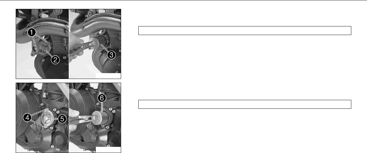
MAINTENANCE WORK ON CHASSIS AND ENGINE 136
100202-10
–Remove screws. Remove oil filter coverwith O-ring.
–Pull the oil filter insertout of the oil filter casing.
Circlip pliers reverse (51012011000)
100203-10
–Remove screws. Remove oil filter coverwith O-ring.
–Pull the oil filter insertout of the oil filter casing.
Circlip pliers reverse (51012011000)
–Completely drain the engine oil.
–Thoroughly clean parts and sealing area.
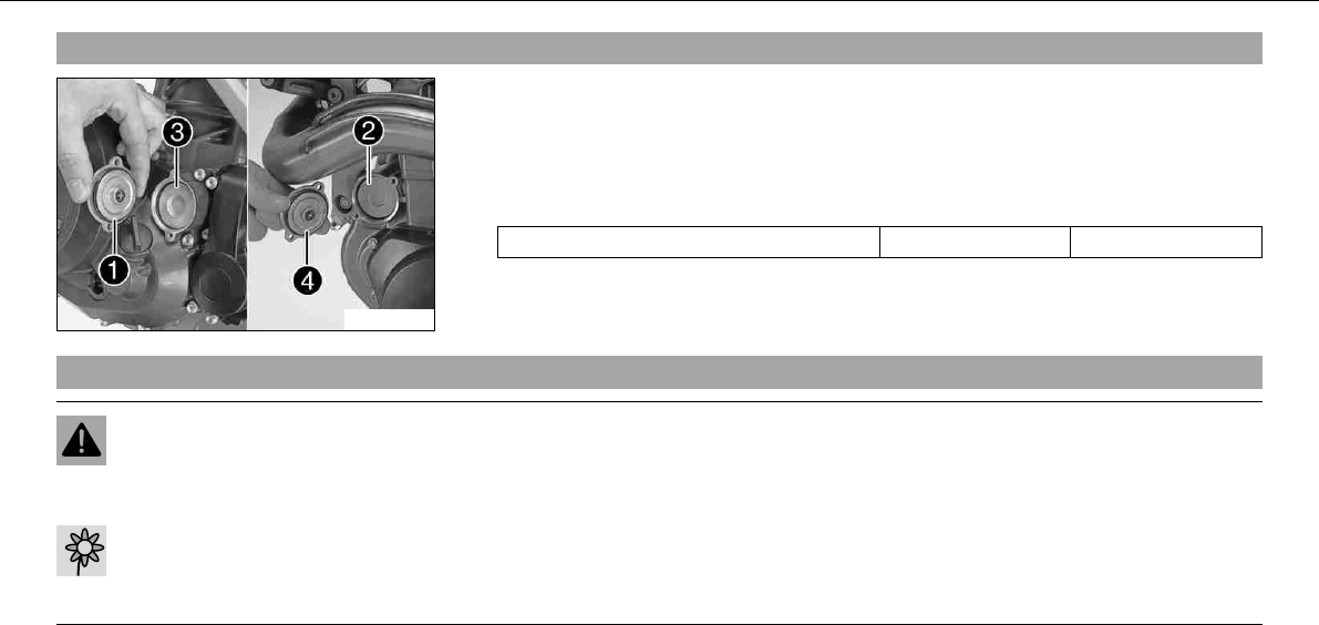
MAINTENANCE WORK ON CHASSIS AND ENGINE 137
9.80Mounting oil filterx
100204-10
–Check parts for damage and wear. Replace damaged or worn parts.
–Insert oil filterand.
–Oil the O-rings of the oil filter cover. Refit the oil filter coverand.
–Mount and tighten screws.
Specification
Screw, oil filter cover M5 6Nm (4.4lbfft)
9.81Cleaning oil screensx
Warning
Danger of scalding Engine oil and gear oil get very hot when the motocycle is driven.
–Wear suitable protective clothing and gloves. If you scald yourself, hold the affected area under cold water immediately.
Warning
Environmental hazard Problem materials cause environmental damage.
–Dispose of oil, grease, filters, fuel, cleaning substances, brake fluid, batteries, etc. according to regulations.
–Place a suitable container under the engine.
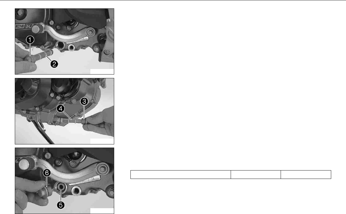
MAINTENANCE WORK ON CHASSIS AND ENGINE 138
100205-10
–Remove the plugwith the oil screenand O-rings.
100206-10
–Remove the plugwith the oil screenand O-rings.
–Drain the remaining engine oil.
–Thoroughly clean parts and sealing area.
–Check parts for damage and wear. Replace damaged or worn parts.
100207-10
–Position oil screenwith O-rings.
–Refit plugwith O-ring and tighten it.
Specification
Plug, oil screen M20x1,5 15Nm (11.1lbfft)
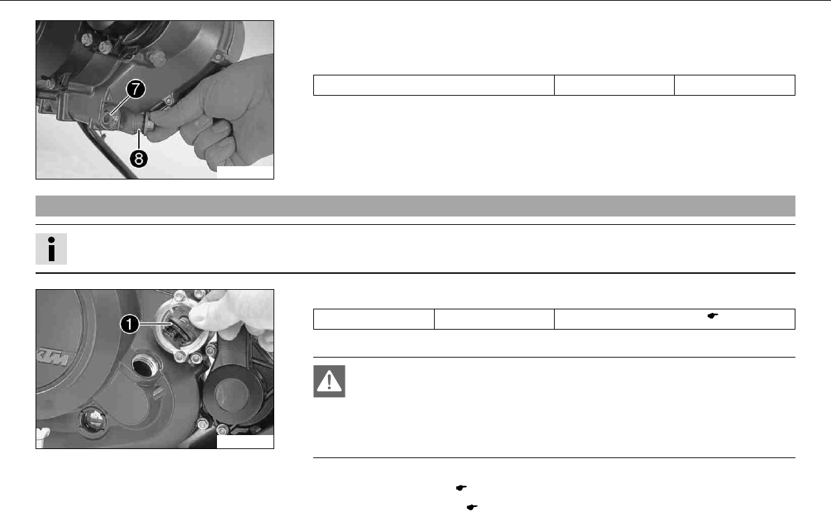
MAINTENANCE WORK ON CHASSIS AND ENGINE 139
100208-10
–Position oil screenwith O-rings.
–Refit plugwith O-ring and tighten it.
Specification
Plug, oil screen M20x1,5 15Nm (11.1lbfft)
9.82Filling up with engine oilx
Info
Too little engine oil or poor-quality engine oil results in premature wear to the engine.
100209-10
–Remove filler plug with O-ringfrom the clutch cover and add engine oil.
Engine oil 1.70l (1.8qt.) Engine oil (SAE 10W/60) ( P. 167)
–Refit plug with O-ringand tighten it.
Danger
Danger of poisoning Exhaust gases are poisonous and can result in
unconsciousness and/or death.
–When running the engine, always make sure there is sufficient ventilation,
and do not start or run the engine in a closed space.
–Start the engine and check that it is oil-tight.
–Install the engine guard. ( P. 132)
–Check the engine oil level. ( P. 133)
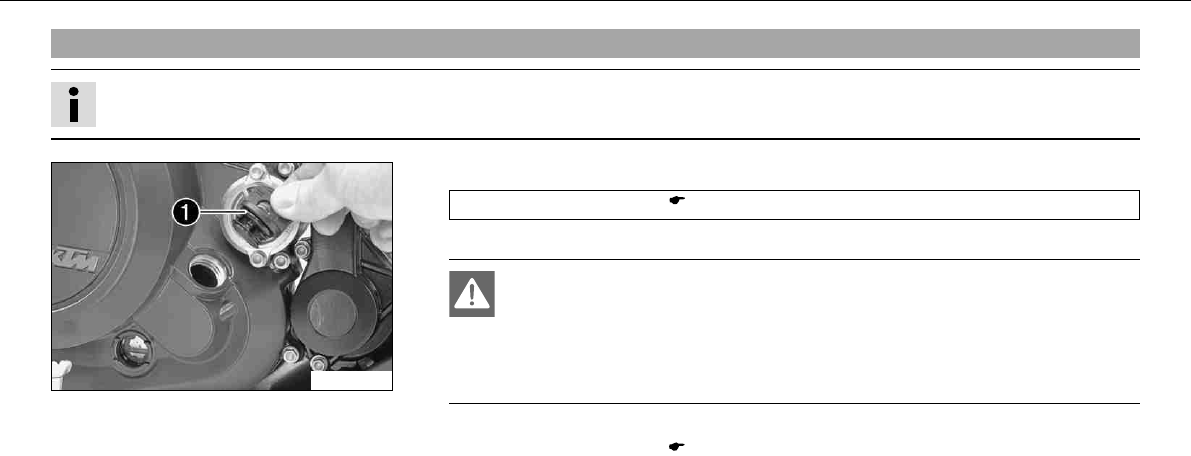
MAINTENANCE WORK ON CHASSIS AND ENGINE 140
9.83Topping up engine oil
Info
Too little engine oil or poor-quality engine oil results in premature wear to the engine.
100209-10
–Remove filler plug with O-ringfrom the clutch cover and add engine oil.
Engine oil (SAE 10W/60) ( P. 167)
–Refit plug with O-ringand tighten it.
Danger
Danger of poisoning Exhaust gases are poisonous and can result in
unconsciousness and/or death.
–When running the engine, always make sure there is sufficient ventilation,
and do not start or run the engine in a closed space.
–Start the engine and check that it is oil-tight.
–Check the engine oil level. ( P. 133)
TROUBLESHOOTING 141
10TROUBLESHOOTING
Faults Possible cause Action
Engine does not turn when the electric
starter button is pressed
Operating error –Carry out the instructions for starting.
( P. 43)
Battery discharged –Recharge the battery.x( P. 105)
–Check the cause of discharging.
Fuse1,2,3,or4blown –Change the fuses of individual power
consumers. ( P. 109)
Main fuse burned out –Change the main fuse. ( P. 107)
Ignition/steering lock or emergency OFF
switch defective
–Have ignition/steering lock or emergency
OFF switch checked.
Defect in safety start system –Have the safety start system checked.
Engine turns only if the clutch lever is
drawn
The vehicle is in gear –Shift gear to neutral.
The vehicle is in gear and the side stand is
folded out
–Shift gear to neutral.
Defect in safety start system –Have the safety start system checked.
Engine turns although a gear is engaged Defect in safety start system –Have the safety start system checked.
Engine turns but does not start. Operating error –Carry out the instructions for starting.
( P. 43)
Fuse4blown –Change the fuses of individual power
consumers. ( P. 109)
Coupling of fuel hose connection not con-
nected
–Reconnect coupling of fuel hose connec-
tion.
Socket connector of cable harness oxidized –Clean socket connector and treat it with
contact spray.
Defect in fuel injection system –Read the error memory with the KTM
diagnostics tool and correct the fault.
Engine has too little power. Air filter very dirty –Have the air filter changed.
TROUBLESHOOTING 142
Faults Possible cause Action
Engine has too little power. Fuel filter very dirty –Have the fuel filter changed.
Defect in fuel injection system –Read the error memory with the KTM
diagnostics tool and correct the fault.
Engine overheats. Too little coolant in cooling system –Check the cooling system for leakage.
–Check the coolant level. ( P. 124)
Radiator fins very dirty –Clean radiator fins.
Foam formation in cooling system –Drain the coolant.x( P. 126)
–Fill the cooling system.x( P. 127)
Buckled or damaged radiator hose –Have the radiator hose changed.
Thermostat defective –Have thermostat checked.
Fuse5blown –Change the fuses of individual power
consumers. ( P. 109)
Defect in radiator fan system –Have the radiator fan system checked.
Air in cooling system –Fill the cooling system.x( P. 127)
FIwarning lamp (MIL) lights/flashes Defect in fuel injection system –Read the error memory with the KTM
diagnostics tool and correct the fault.
Engine dies during the journey Lack of fuel –Fill up with fuel. ( P. 51)
Fuse1,2or4blown –Change the fuses of individual power
consumers. ( P. 109)
High oil consumption Engine vent hose bent –Route the vent hose without bends or
change it if necessary.
Engine oil level too high –Check the engine oil level. ( P. 133)
Engine oil too thin (low viscosity) –Change engine oil and oil filter, clean oil
screens.x( P. 133)
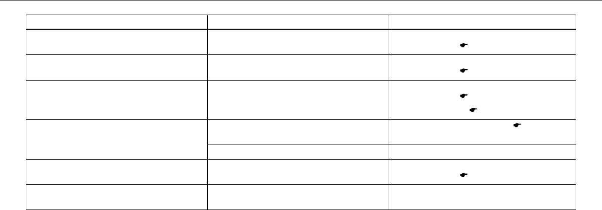
TROUBLESHOOTING 143
Faults Possible cause Action
Headlight and parking light not functioning Fuse7blown –Change the fuses of individual power
consumers. ( P. 109)
Flasher light, brake light and horn not
functioning
Fuse6blown –Change the fuses of individual power
consumers. ( P. 109)
Time is not (correctly) displayed Fuse2blown –Change the fuses of individual power
consumers. ( P. 109)
–Set the clock. ( P. 29)
Battery discharged Ignition not switched off when vehicle was
parked
–Recharge the battery.x( P. 105)
Battery is not charged by generator –Check charging voltage.
Combination instrument shows nothing in
the display
Fuse1blown –Change the fuses of individual power
consumers. ( P. 109)
Speedometer in combination instrument
not functioning
Speedometer cable harness damaged or
plug oxidized
–Have the cable harness and plug
checked.

FLASHING CODE 144
11FLASHING CODE
Fault Description Possible cause Action
02 FIwarning lamp (MIL) flashes
briefly 2x
Malfunction in ignition pulse
generator circuit
–Check the ignition pulse
generator.x
06 FIwarning lamp (MIL) flashes
briefly 6x
Input signal from throttle valve
sensor too low/high
–Check the throttle valve sen-
sor.x
08 FIwarning lamp (MIL) flashes
briefly 8x
Input signal from throttle grip
sensor too low/high
–Check the throttle grip sen-
sor.x
09 FIwarning lamp (MIL) flashes
briefly 9x
Input signal from pressure sen-
sor of induction manifold too
low/high
–Check the pressure sen-
sor of the induction mani-
fold.x
12 FIwarning lamp (MIL) flashes 1x
long, 2x short
Input signal from coolant tem-
perature sensor too low/high
–Check the temperature sen-
sor coolant.x
13 FIwarning lamp (MIL) flashes 1x
long, 3x short
Input signal from intake air
temperature sensor too low/high
–Check the intake air temper-
ature sensor.x
14 FIwarning lamp (MIL) flashes 1x
long, 4x short
Input signal from ambient air
pressure sensor too low/high
–Check the ambient air pres-
sure sensor.x
15 FIwarning lamp (MIL) flashes 1x
long, 5x short
Input signal from roll angle sen-
sor too low/high
–Check the roll angle sen-
sor.x
17 FIwarning lamp (MIL) flashes 1x
long, 7x short
Malfunction in lambda probe
circuit
–Check the lambda probe.x
24 FIwarning lamp (MIL) flashes 2x
long, 4x short
Malfunction in voltage supply
circuit of EFI control unit
–Check the EFI control unit
voltage supply.x
25 FIwarning lamp (MIL) flashes 2x
long, 5x short
Malfunction in side stand
switch circuit
–Check the side stand
switch.x
26 FIwarning lamp (MIL) flashes 2x
long, 6x short
Malfunction in Hall sensor
throttle valve control circuit
–Check the Hall sensor throt-
tle valve control.x

FLASHING CODE 145
Fault Description Possible cause Action
27 FIwarning lamp (MIL) flashes 2x
long, 7x short
Malfunction in voltage supply
circuit of throttle valve control
unit
–Check the throttle valve con-
trol unit voltage supply.x
33 FIwarning lamp (MIL) flashes 3x
long, 3x short
Malfunction in injection valve
circuit
–Check the injection
valve.x
37 FIwarning lamp (MIL) flashes 3x
long, 7x short
Malfunction in ignition coil cir-
cuit
–Check the ignition coil.x
41 FIwarning lamp (MIL) flashes 4x
long, 1x short
Fault/short-circuit in fuel pump
control circuit
–Check the fuel pump con-
trol.x
45 FIwarning lamp (MIL) flashes 4x
long, 5x short
Malfunction or short-circuit
after positive in lambda probe
heating circuit
–Check the lambda probe
heating.x
54 FIwarning lamp (MIL) flashes 5x
long, 4x short
Fault/short-circuit in secondary
air valve circuit
–Check the secondary air
valve.x
55 FIwarning lamp (MIL) flashes 5x
long, 5x short
Malfunction in throttle valve
control unit circuit (internal)
–Check the throttle valve con-
trol unit.x
58 FIwarning lamp (MIL) flashes 5x
long, 8x short
Malfunction in release of throt-
tle stepper in EPT mode
–Check the throttle valve con-
trol unit.x
–Check the EFI control
unit.x
60 FIwarning lamp (MIL) flashes 6x
long
Malfunction in throttle stepper
circuit
–Check the throttle stepper
motor.x
68 FIwarning lamp (MIL) flashes 6x
long, 8x short
Connection of pressure sensor
of induction manifold leaky
–Check the connection of
the pressure sensor of the
induction manifold.x
90 FIwarning lamp (MIL) flashes 9x
long
Throttle valve position not plau-
sible
–Check the throttle valve
position.x
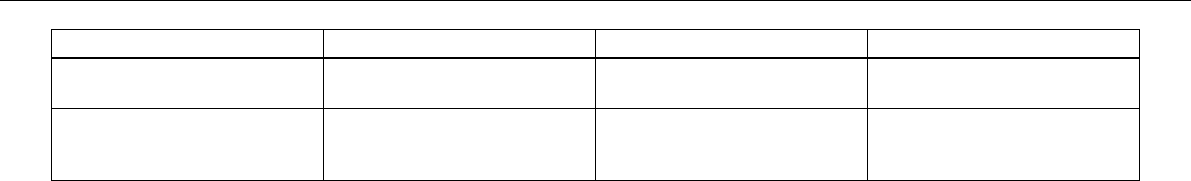
FLASHING CODE 146
Fault Description Possible cause Action
91 FIwarning lamp (MIL) flashes 9x
long, 1x short
Malfunction in CAN bus com-
munication
–Check CAN bus communica-
tion.x
92 FIwarning lamp (MIL) flashes 9x
long, 2x short
Malfunction in voltage supply
circuit of throttle valve control
unit (internal)
–Check the throttle valve con-
trol unit.x
CLEANING 147
12CLEANING
12.1
Cleaning motorcycle
Note
Material damage Damage and destruction of components by high-pressure cleaning equipment.
–Never clean the vehicle with high-pressure cleaning equipment or a strong water-jet. The excessive pressure can penetrate electrical
components, connects, Bowden cables, and bearings, etc., and can damage or destroy these parts.
Warning
Environmental hazard Problem materials cause environmental damage.
–Dispose of oil, grease, filters, fuel, cleaning substances, brake fluid, batteries, etc. according to regulations.
Info
If you clean the motorcycle regularly, its value and appearance are maintained over a long period.
Avoid direct sunshine on the motorcycle during cleaning.
–Before you clean the motocycle, seal the exhaust system to prevent penetration by water.
–First remove coarse dirt particles with a gentle water spray.
–Spray very dirty areas with a normal motorcycle cleaner and then clean with a paintbrush.
Motorcycle cleaner ( P. 170)
Info
Use warm water containing normal motorcycle cleaner and a soft sponge.
If you have ridden the vehicle on salted roads, clean it with cold water. Warm water would reinforce the effect of the salt.
–After rinsing the motorcycle thoroughly with a soft jet of water, dry it with compressed air and a cloth.
CLEANING 148
Warning
Danger of accidents Reduced braking due to wet or dirty brakes.
–Clean or dry dirty or wet brakes by riding and braking gently.
–After cleaning, ride the vehicle a short distance until the engine warms up, and then apply the brakes.
Info
The heat produced causes water at inaccessible positions in the engine and the brakes to evaporate.
–Push back the protection covers on the handlebar instruments to allow water to evaporate.
–After the motorcycle has cooled off, oil or grease all moving parts and bearings.
–Clean the chain. ( P. 69)
–Treat bare metal parts (except for brake discs and exhaust system) with anti-corrosion materials.
Cleaning and polishing materials for metal, rubber and plastic ( P. 169)
–Treat all painted parts with a mild paint polish.
High-luster polish for paint ( P. 169)
–To prevent electrical problems, treat electric contacts and switches with contact spray.
Contact spray ( P. 169)
–Oil the ignition/steering lock.
Universal oil spray ( P. 170)
CONSERVATION FOR WINTER OPERATION 149
13CONSERVATION FOR WI NTER OPERATION
13.1
Conservation for winter operation
Info
If you use the motorcycle in winter, you must expect salt on the roads. You should therefore take precautions against aggressive
road salt.
If you have ridden the vehicle on salted roads, clean it with cold water. Warm water would reinforce the effect of the salt.
–Clean the motorcycle. ( P. 147)
–Treat the engine, the swingarm, and all other bare or galvanized parts (except brake discs) with a wax-based anti-corrosion substance.
Info
To prevent serious reduction of the braking efficiency, make sure no anti-corrosion substance gets on to the brake discs.
After use on salted roads, clean the motorcycle thoroughly with cold water and dry it properly.
–Clean the chain. ( P. 69)
STORAGE 150
14STORAGE
14.1Storage
Info
If you want to garage the motorcycle for a longer period, take the following actions.
Before storing the motorcycle, check all parts for function and wear. If service, repairs or replacements are necessary, you should
do this during the storage period (less workshop overload). In this way, you can avoid long workshop waiting times at the start of the
new season.
–Make sure the tank is as empty as possible so that you can fill up with fresh fuel when you put the motorcycle back into operation.
–Clean the motorcycle. ( P. 147)
–Change engine oil and oil filter, clean oil screens.x( P. 133)
–Check the antifreeze and coolant level. ( P. 122)
–Checking the tire air pressure. ( P. 100)
–Remove the battery.x( P. 103)
–Recharge the battery.x( P. 105)
Specification
Storage temperature of battery without direct sunshine. 0… 35°C (32… 95°F)
–The storage place should be dry and not subject to large temperature differences.
Info
KTM recommends jacking up the motorcycle.
–Jack up the motorcycle. ( P. 56)
STORAGE 151
–Cover the motorcycle with a porous sheet or blanket.
Info
Do not use non-porous materials since they prevent humidity from escaping, thus causing corrosion.
Avoid running the engine for a short time only. Since the engine cannot warm up properly, the water vapor produced during
combustion condenses and causes valves and exhaust system to rust.
14.2Putting into operation after storage
–Remove the motorcycle from the work stand. ( P. 56)
–Recharge the battery.x( P. 105)
–Install the battery.x( P. 104)
–Set the clock. ( P. 29)
–Fill up with fuel. ( P. 51)
–Carry out checks before putting into operation. ( P. 42)
–Make a test ride.

TECHNICAL DATA - ENGINE 152
15TECHNICAL DATA - ENGIN E
Design 1-cyliner 4-stroke engine, water-cooled
Displacement 654cm³ (39.91cuin)
Stroke 80mm (3.15in)
Bore 102mm (4.02in)
Compression ratio 11,8:1
Control OHC, 4 valves controlled via rocker arm, chain drive
Valve diameter, intake 40mm (1.57in)
Valve diameter, exhaust 34mm (1.34in)
Valve play, cold 0.07… 0.13mm (0.0028… 0.0051in)
Crankshaft bearing 2 roller bearings
Conrod bearing Needle bearing
Piston pin bearing Bronze bush
Pistons Forged light alloy
Piston rings 1 L-ring, 1 tapered compression piston ring, 1 oil scraper ring
Engine lubrication Pressure circulation lubrication with 2 rotor pumps
Primary transmission 36:79
Clutch APTC antihopping clutch in oil-bath / hydraulically actuated
Gearbox 6-gears, claw-shifted
Transmission ratio
1st gear 14:35
2nd gear 16:28
3rd gear 21:28
4th gear 21:23
5th gear 23:22
TECHNICAL DATA - ENGINE 153
6th gear 23:20
Mixture preparation Electronic fuel injection
Ignition Contactless controlled fully electronic ignition with digital ignition
adjustment
Generator 12V, 224W
Spark plug NGK LKAR 8AI - 9
spark plug electrode gap 0.9mm (0.035in)
Cooling Water cooling, permanent circulation of coolant by water pump
Starting aid Electric starter, automatic decompressor
15.1Capacity - engine oil
Engine oil 1.70l (1.8qt.) Engine oil (SAE 10W/60) ( P. 167)
15.2Capacity - coolant
Coolant 1.20l (1.27qt.) Coolant ( P. 166)
Coolant (mixed ready to use) ( P. 166)

TECHNICAL DATA - ENGINE TIGHTENING TORQUES 154
16TECHNICAL DATA - ENGINE T IGHTENING TORQUES
Plug, oil bore self-tapping 9Nm (6.6lbfft) Loctite®243™
Screw, membrane fixation M3 2.5Nm (1.84lbfft) Loctite®243™
Oil jet, conrod lubrication M4 2Nm (1.5lbfft) Loctite®243™
Hose clamp, intake flange M4 1.5Nm (1.11lbfft) –
Screw, cover plate for oil return line M5 6Nm (4.4lbfft) –
Screw, breather cover on valve cover M5 3Nm (2.2lbfft) Loctite®243™
Screw, gear sensor M5 5Nm (3.7lbfft) Loctite®243™
Screw, clutch spring M5 6Nm (4.4lbfft) –
Locking screw for bearing M5 6Nm (4.4lbfft) Loctite®648™
Screw, oil filter cover M5 6Nm (4.4lbfft) –
Screw, oil pump cover M5 6Nm (4.4lbfft) Loctite®243™
Oil jet, piston cooling M6x0.75 4Nm (3lbfft) Loctite®243™
Screw, locking lever M6 10Nm (7.4lbfft) Loctite®243™
Screw, Autodecompression M6 3… 4Nm (2.2… 3lbfft) Loctite®243™
Screw, axial lock of camshaft M6 10Nm (7.4lbfft) Loctite®243™
Screw, timing chain guide rail M6 10Nm (7.4lbfft) Loctite®243™
Screw generator cover M6 10Nm (7.4lbfft) –
Screw in generator cover (chain shaft
through-hole)
M6 10Nm (7.4lbfft) Loctite®243™
Screw, ignition pulse generator M6 10Nm (7.4lbfft) Loctite®243™
Screw, rocker arm shaft M6 12Nm (8.9lbfft) –
Screw, clutch cover M6 10Nm (7.4lbfft) –
Screw, clutch slave cylinder M6x20 10Nm (7.4lbfft) Loctite®243™
Screw, clutch slave cylinder M6x35 10Nm (7.4lbfft) –

TECHNICAL DATA - ENGINE TIGHTENING TORQUES 155
Screw, engine housing M6 10Nm (7.4lbfft) –
Screw, shift drum locating M6 10Nm (7.4lbfft) Loctite®243™
Screw, shift lever M6 10Nm (7.4lbfft) Loctite®222
Screw, timing chain tensioning rail M6 10Nm (7.4lbfft) Loctite®243™
Screw, starter motor M6 10Nm (7.4lbfft) Loctite®243™
Screw, stator bracket M6 10Nm (7.4lbfft) Loctite®243™
Screw, thermostat housing M6 10Nm (7.4lbfft) Loctite®243™
Screw, valve cover M6 10Nm (7.4lbfft) –
Screw, water pump cover M6 10Nm (7.4lbfft) –
Screw, water pump wheel M6 10Nm (7.4lbfft) Loctite®243™
Screw, cylinder M6 10Nm (7.4lbfft) Loctite®243™
Screw, cylinder head M6 10Nm (7.4lbfft) Loctite®243™
Plug, vacuum connection M6 10Nm (7.4lbfft) Loctite®243™
Stud, exhaust flange M8 10Nm (7.4lbfft) Loctite®243™
Plug, crankshaft location M8 20Nm (14.8lbfft) –
Screw, unlocking of timing chain ten-
sioner
M10x1 10Nm (7.4lbfft) –
Plug, drain hole of water pump M10x1 15Nm (11.1lbfft) –
Plug, oil bore for oil radiator M10x1 15Nm (11.1lbfft) –
Plug, oil bore M10x1 15Nm (11.1lbfft) Loctite®243™

TECHNICAL DATA - ENGINE TIGHTENING TORQUES 156
Screw, cylinder head M10 Tightening sequence:
Tighten diagonally, beginning
with the rear screw on the
chain shaft.
Step 1
15Nm (11.1lbfft)
Step 2
30Nm (22.1lbfft)
Step 3
45Nm (33.2lbfft)
Step 4
60Nm (44.3lbfft)
lubricated with engine oil
Spark plug M12x1,25 17Nm (12.5lbfft) –
Coolant temperature sensor on cylinder
head
M12x1.5 12Nm (8.9lbfft) –
Oil drain plug with magnet M12x1,5 20Nm (14.8lbfft) –
Oil pressure regulator valve plug M12x1.5 20Nm (14.8lbfft) –
Plug, oil bore M14x1,5 15Nm (11.1lbfft) Loctite®243™
Engine case stud M16x1.5 25Nm (18.4lbfft) Loctite®243™
Ignition rotor nut M18x1,5 100Nm (73.8lbfft) –
Nut, engine sprocket M20x1,5 60Nm (44.3lbfft) Loctite®243™
Nut, inner clutch hub M20x1,5 100Nm (73.8lbfft) Loctite®243™
Nut, primary gear M20LHx1,5 100Nm (73.8lbfft) Loctite®243™
Plug, oil screen M20x1,5 15Nm (11.1lbfft) –
Plug, timing chain tensioner M20x1,5 25Nm (18.4lbfft) –
Screw in generator cover M24x1.5 8Nm (5.9lbfft) –
Plug, oil thermostat M24x1,5 15Nm (11.1lbfft) –

TECHNICAL DATA - CHASSIS 157
17TECHNICAL DATA - CHAS SIS
Frame Lattice frame made of chrome molybdenum steel tubing, powder-
coated
Fork WP 4860 MXMA
Shock absorber WPSuspension4618 with Pro‑Lever deflector
Suspension travel
front 250mm (9.84in)
Rear 250mm (9.84in)
Brake system
front Disc brake with dual-piston brake caliper, floating
Rear Disc brake with single-piston brake caliper, floating
Diameter of brake discs
front 300mm (11.81in)
Rear 240mm (9.45in)
Wear limit of brake discs
front 4.5mm (0.177in)
Rear 3.5mm (0.138in)
Tire air pressure, road, solo
front 1.8bar (26psi)
Rear 1.8bar (26psi)
Tire air pressure with passenger / fully loaded
front 2.0bar (29psi)
Rear 2.2bar (32psi)
Tire air pressure, offroad, single rider
front 1.5bar (22psi)
Rear 1.5bar (22psi)

TECHNICAL DATA - CHASSIS 158
Rear wheel gearing 15:45
Chain 5/8x1/4” X‑ring
Steering head angle 63°
Wheelbase 1,498±15mm (58.98±0.59in)
Seat height unloaded 910mm (35.83in)
Ground clearance unloaded 300mm (11.81in)
Weight without fuel 138.5kg (305.3lb.)
Maximum permissible front axle load 150kg (331lb.)
Maximum permissible rear axle load 200kg (441lb.)
Maximum permissible overall weight 350kg (772lb.)
Battery YTZ10S Battery voltage: 12V
Nominal capacity: 8.6Ah
maintenance-free
Fuse 58011109130 30A
Fuse 75011088015 15A
Fuse 75011088010 10A
17.1Lighting equipment
Headlight H4/P43t 12V
60/55W
Parking light W2,1x9,5d 12V
5W
Instrument lights and indicator lamps LED
Flasher light BA15s 12V
10W
TECHNICAL DATA - CHASSIS 159
Brake / tail light LED
Licence plate lamp W2,1x9,5d 12V
5W
Front tire Rear tire
90/90-2154HTL
Metzeler Enduro3Sahara
140/80-1870HTL
Metzeler Enduro3Sahara
For further information, see the Service section under:
http://www.ktm.com
17.2Capacity - fuel
Fuel tank content 12l (3.2USgal) Super unleaded (ROZ 95 / RON 95 / PON 91) ( P. 168)
Fuel reserve 2.5l (2.6qt.)

TECHNICAL DATA - FORK 160
18TECHNICAL DATA - FORK
Fork part number 14.18.7D.11
Fork WP 4860 MXMA
Compression damping
Comfort 20clicks
Standard 15clicks
Sport 10clicks
full payload 10clicks
Rebound damping
Comfort 20clicks
Standard 15clicks
Sport 10clicks
full payload 10clicks
Spring length with preload spacer(s) 472mm (18.58in)
Spring rate
Weight of rider: 75… 85kg (165… 187lb.) 5.4N/mm (30.8lb/in)
Air chamber length 110±20mm (4.33±0.79in)
Fork length 890mm (35.04in)
Fork oil ( P. 167) SAE 5

TECHNICAL DATA - SHOCK ABSORBER 161
19TECHNICAL DATA - SHOCK AB SORBER
Shock absorber part number 15.18.7D.11
Shock absorber WPSuspension4618 with Pro‑Lever deflector
Compression damping, high-speed
Comfort 2turns
Standard 1.5turns
Sport 1turn
full payload 1turn
Compression damping, low-speed
Comfort 20clicks
Standard 15clicks
Sport 10clicks
full payload 10clicks
Rebound damping
Comfort 20clicks
Standard 15clicks
Sport 10clicks
full payload 10clicks
Spring preload 19mm (0.75in)
Spring rate
Weight of rider: 75… 85kg (165… 187lb.) 80N/mm (457lb/in)
Spring length 220mm (8.66in)
Gas pressure 10bar (145psi)
Static sag 25mm (0.98in)
Riding sag 80… 90mm (3.15… 3.54in)

TECHNICAL DATA - SHOCK ABSORBER 162
Fitted length 395mm (15.55in)

TECHNICAL DATA - CHASSIS TIGHTENING TORQUES 163
20TECHNICAL DATA - CHASSIS T IGHTENING TORQUES
Remaining screws, chassis M5 4Nm (3lbfft) –
Spoke nipple, front wheel M5 4Nm (3lbfft) –
Spoke nipple, rear wheel M5 4Nm (3lbfft) –
Screw, exhaust heat shield M5 8Nm (5.9lbfft) –
Screw, electrical holder M5 3Nm (2.2lbfft) –
Screw, footbrake pedal foothold M5 6Nm (4.4lbfft) Loctite®243™
Screw, fuel pump M5 6Nm (4.4lbfft) –
Screw, fuel level indicator M5 3Nm (2.2lbfft) –
Screw, side cover M5 2Nm (1.5lbfft) –
Screw, headlight mask M5 5Nm (3.7lbfft) –
Screw, side stand switch M5 3Nm (2.2lbfft) –
Screw, seat lock M5 3Nm (2.2lbfft) Loctite®222
Screw, starter cable on starter M5 3Nm (2.2lbfft) –
Nut, foot brake cylinder screw M6 10Nm (7.4lbfft) –
Remaining nuts, chassis M6 15Nm (11.1lbfft) –
Remaining screws on fuel tank M6 6Nm (4.4lbfft) –
Remaining screws, chassis M6 10Nm (7.4lbfft) –
Screw, brake fluid reservoir of rear brake M6 5Nm (3.7lbfft) –
Screw, rear brake disc M6 14Nm (10.3lbfft) Loctite®243™
Screw, front brake disc M6 14Nm (10.3lbfft) Loctite®243™
Screw, license plate holder, bottom M6 8Nm (5.9lbfft) –
Screw, ball joint of push rod on foot-
brake cylinder
M6 10Nm (7.4lbfft) Loctite®243™
Screw, radiator bracket M6 5Nm (3.7lbfft) –

TECHNICAL DATA - CHASSIS TIGHTENING TORQUES 164
Screw, magnetic holder on side stand M6 10Nm (7.4lbfft) Loctite®243™
Screw, voltage regulator/rectifier M6 8Nm (5.9lbfft) –
Screw, SLS valve M6 4Nm (3lbfft) –
Screw, ignition lock M6 10Nm (7.4lbfft) Loctite®243™
Nut, rear sprocket screw M8 35Nm (25.8lbfft) Loctite®243™
Nut, manifold on cylinder head M8 25Nm (18.4lbfft) Copper paste
Remaining nuts, chassis M8 30Nm (22.1lbfft) –
Remaining screws, chassis M8 25Nm (18.4lbfft) –
Screw, exhaust clamp on main silencer M8 25Nm (18.4lbfft) –
Screw, front brake caliper M8 25Nm (18.4lbfft) Loctite®243™
Screw, main silencer holder M8 25Nm (18.4lbfft) –
Screw, main silencer holder on fuel tank M8 25Nm (18.4lbfft) Loctite®243™
Screw, rear footrest bracket M8x16 25Nm (18.4lbfft) –
Screw, front footrest bracket M8 25Nm (18.4lbfft) –
Screw, spring holder on side stand
bracket
M8 25Nm (18.4lbfft) Loctite®243™
Screw, top triple clamp M8 17Nm (12.5lbfft) –
Screw, bottom triple clamp M8 12Nm (8.9lbfft) –
Screw, fork stub M8 15Nm (11.1lbfft) –
Screw, steering stem M8 20Nm (14.8lbfft) Loctite®243™
Screw, handrail M8 20Nm (14.8lbfft) –
Screw, license plate holder, top M8 20Nm (14.8lbfft) –
Screw, fuel tank, top M8 25Nm (18.4lbfft) Loctite®243™
Screw, fuel tank, bottom M8 25Nm (18.4lbfft) –

TECHNICAL DATA - CHASSIS TIGHTENING TORQUES 165
Screw, handlebar clamp M8 20Nm (14.8lbfft) Loctite®243™
Screw, side stand bracket M8 25Nm (18.4lbfft) –
Screw, connection lever on frame M8 30Nm (22.1lbfft) –
Remaining nuts, chassis M10 50Nm (36.9lbfft) –
Remaining screws, chassis M10 45Nm (33.2lbfft) –
Engine carrying screw M10 45Nm (33.2lbfft) Loctite®243™
Screw, top shock absorber M10 45Nm (33.2lbfft) Loctite®243™
Screw, bottom shock absorber M10 45Nm (33.2lbfft) Loctite®243™
Screw, foot brake pedal M10LH 25Nm (18.4lbfft) Loctite®243™
Screw, handlebar support M10 40Nm (29.5lbfft) –
Screw, engine bearer on frame M10 45Nm (33.2lbfft) –
Screw, side stand M10 35Nm (25.8lbfft) Loctite®243™
Lambda probe M12x1.25 24.5Nm (18.07lbfft) –
Screw, swingarm pivot M12x1.75 80Nm (59lbfft) –
Nut, linkage lever to rocker arm M14x1.5 100Nm (73.8lbfft) –
Nut, linkage lever on swingarm M14x1.5 100Nm (73.8lbfft) –
Screw, top steering head M20x1.5 10Nm (7.4lbfft) –
Screw, bottom steering head M20x1.5 60Nm (44.3lbfft) Loctite®243™
Screw, front wheel spindle M24x1.5 40Nm (29.5lbfft) –
Nut, rear wheel spindle M25x1.5 90Nm (66.4lbfft) –
SUBSTANCES 166
21SUBSTANCES
Brake fluid DOT4/DOT5.1
according to
–DOT
Specification
–Use only brake fluid that complies with the specified standards (see specifications on the container) and that possesses the corre-
sponding properties. KTM recommendsCastrol andMotorex®products.
Supplier
Castrol
–RESPONSEBRAKEFLUIDSUPERDOT4
Motorex®
–BrakeFluidDOT5.1
Coolant
Specification
–Use only suitable coolant (even in countries with high temperatures). Using inferior antifreeze can result in corrosion and foaming.
KTM recommends Motorex®products.
Mixture ratio
Antifreeze: −25… −45°C (−13… −49°F) 50% Anti-corrosion/antifreeze
50% distilled water
Coolant (mixed ready to use)
Antifreeze −40°C (−40°F)
Supplier
Motorex®
–AntiFreeze
SUBSTANCES 167
Engine oil (SAE 10W/60)
according to
–JASOT903MA ( P. 171)
–SAE ( P. 171) (SAE 10W/60)
Specification
–Use only engine oils that comply with the specified standards (see specifications on the container) and that possess the corresponding
properties. KTM recommends Motorex®products.
Synthetic engine oil
Supplier
Motorex®
–CrossPower4T
Fork oil (SAE 5)
according to
–SAE ( P. 171) (SAE 5)
Specification
–Use only oils that comply with the specified standards (see specifications on the container) and that possesses the corresponding prop-
erties. KTM recommends Motorex®products.
Supplier
Motorex®
–RacingForkOil
Hydraulic fluid (15)
according to
–ISO VG (15)

SUBSTANCES 168
Specification
–Use only hydraulic fluid that complies with the specified standards (see specifications on the container) and that possesses the corre-
sponding properties. KTM recommends Motorex®products.
Supplier
Motorex®
–HydraulicFluid75
Super unleaded (ROZ 95 / RON 95 / PON 91)
according to
–DINEN228 (ROZ 95 / RON 95 / PON 91)

AUXILIARY SUBSTANCES 169
22AUXILIARY SUBSTANCES
Chain cleaner
Specification
–KTM recommendsMotorex®products.
Supplier
Motorex®
–ChainClean611
Cleaning and polishing materials for metal, rubber and plastic
Specification
–KTM recommendsMotorex®products.
Supplier
Motorex®
–Protect&Shine645
Contact spray
Specification
–KTM recommendsMotorex®products.
Supplier
Motorex®
–AccuContact
High-luster polish for paint
Specification
–KTM recommendsMotorex®products.
Supplier
Motorex®
–MotoPolish

AUXILIARY SUBSTANCES 170
Long-life grease
Specification
–KTM recommendsMotorex®products.
Supplier
Motorex®
–LongTherm2000
Motorcycle cleaner
Specification
–KTM recommendsMotorex®products.
Supplier
Motorex®
–MotoClean900
Offroad chain spray
Specification
–KTM recommends Motorex®products.
Supplier
Motorex®
–ChainLube622
Universal oil spray
Specification
–KTM recommendsMotorex®products.
Supplier
Motorex®
–Joker440Universal

STANDARDS 171
23STANDARDS
JASOT903MA
Different technical development directions required a new specification for 4-stroke motorcycles –the JASO T903 MA Standard. Ear-
lier, engine oils from the automobile industry were used for 4-stroke motorcycles because there was no separate motorcycle specification.
Whereas long service intervals are demanded for automobile engines, high performance at high engine speeds are in the foreground for
motorcycle engines. With most motorcycles, the gearbox and the clutch are lubricated with the oil as the engine. The JASO MA Standard
meets these special requirements.
SAE
The SAE viscosity classes were defined by the Society of Automotive Engineers and are used for classifying oils according to their viscos-
ity. The viscosity describes only one property of oil and says nothing about quality.

INDEX 172
INDEX
A
Air filter
fitting ....................................120
removing ..................................119
Antifreeze
checking ..................................122
B
Baggage ......................................40
Battery
fitting ....................................104
recharging .................................105
removing ..................................103
Brake discs
checking ...................................75
Brake fluid
adding brake fluid for front brake . . . . . . . . . . . . . . . . . .78
ofrearbrake,adding ...........................87
Brake fluid level
Checking the front brake brake fluid level . . . . . . . . . . . . 78
ofrearbrake,checking .........................86
Brakelinings .................................. 80
changingforrearbrake .........................89
Changing the front brake linings . . . . . . . . . . . . . . . . . . . 81
of front brake, checking . . . . . . . . . . . . . . . . . . . . . . . . .81
ofrearbrake,checking .........................89
Brakes .......................................48
Braking ......................................48
C
Chain
checkingdirt ................................69
checkingwear ...............................74
cleaning ...................................69
Chain guide
adjusting ...................................75
Chain tension
adjusting ...................................71
checking ...................................70
Chassis number .................................16
Checking headlamp setting .........................118
Cleaning ................................. 147-148
Clutch
checking/correcting fluid level . . . . . . . . . . . . . . . . . . . 129
Clutchlever................................... 19
adjusting basic position . . . . . . . . . . . . . . . . . . . . . . . . 129
Combinationinstrument ........................... 25
Coolant temperature indicator . . . . . . . . . . . . . . . . . . . . 32
Display ....................................27
DisplayODO ................................30
DisplayTRIPF ...............................32
Functionbuttons .............................25
Indicatorlights ...............................26
Setting kilometers or miles . . . . . . . . . . . . . . . . . . . . . . .28
Settingtheclock .............................29

INDEX 173
Setting/resettingTRIP1display ...................30
Setting/resettingTRIP2display ...................31
Speeddisplay ...............................28
Tachometer .................................26
Time ......................................29
Conservation for winter operation .....................149
Coolant
draining ..................................126
Coolant level
checking ..............................122,124
Coolingsystem................................ 121
filling ....................................127
D
Display .......................................27
Dust boots
cleaning ...................................63
E
Electric starter button .............................24
Emergency OFF switch .............................23
Engine
runningin ..................................40
Engine characteristic
adjusting ..................................111
Engine guard
installing ..................................132
removing ..................................132
Engine number ..................................17
Engine oil
changing ..................................133
draining ..................................134
refilling ...................................139
toppingup .................................140
Engine oil level
checking ..................................133
Environment .....................................9
F
Filler cap
closing ....................................33
opening ....................................33
Filling up
Fuel ......................................51
Flasher bulb
changing ..................................117
Flasher switch ............................... 21-22
Flashing code ............................. 144-146
Footbrakepedal................................ 36
adjusting basic position . . . . . . . . . . . . . . . . . . . . . . . . .85
checkingfreeplay ............................85
Fork........................................ 57
Adjusting compression damping . . . . . . . . . . . . . . . . . . .57
Adjustingrebound ............................58
Bleedingforklegs .............................62

INDEX 174
Fork part number ................................18
Fork protector
positioning .................................64
remove ....................................64
Front wheel
fitting .....................................94
removing ...................................92
Fuel, oils, etc. ...................................8
Fuse
of individual power consumer, changing . . . . . . . . . . . . . 109
H
Handbrakelever ............................... 19
adjustingfreetravel ...........................77
checkingfreeplay ............................76
Handlebar angle
adjusting ...................................67
Handlebarposition .............................. 67
adjusting ...................................68
Handrails .....................................34
Headlight
Adjusting the light range . . . . . . . . . . . . . . . . . . . . . . . 119
Headlight bulb, changing ..........................115
Headlight flasher switch ............................21
Headlight mask with headlight
fitting ....................................114
removing ..................................113
Horn ..................................... 22-23
I
Ignition lock ...................................24
Indicator lights ..................................26
K
Key number ....................................17
L
Light switch ....................................20
Loading the vehicle ...............................40
M
Main fuse
changing ..................................107
Maintenance ....................................8
Motorcycle
cleaning ..................................147
jackingup ..................................56
removing from the work stand . . . . . . . . . . . . . . . . . . . . .56
O
Oil filter
changing ..................................133
fitting ....................................137
removing ..................................135
Oil screen
cleaning ..................................133

INDEX 175
Oil screens
cleaning ..................................137
OWNER'S MANUAL
Basics .....................................10
P
Parking ......................................49
Parking light bulb
changing ..................................116
Passenger footrests ...............................35
Play in gas Bowden cable
adjusting ..................................131
checking ..................................130
Putting into operation
Adviceonfirstuse ............................38
afterstorage ...............................151
Checks before putting into operation . . . . . . . . . . . . . . . . 42
R
Rear hub rubber dampers
checking ...................................97
Rear sprocket / engine sprocket
checkingforwear .............................73
Rear wheel
fitting .....................................96
removing ...................................95
Riding ...................................... 45
Startingup .................................45
S
Seat
mounting .................................103
removing ..................................102
Seat release ...................................34
Shift lever .....................................35
Shifting ......................................45
Shockabsorber ................................ 57
adjusting rebound damping . . . . . . . . . . . . . . . . . . . . . .62
compression damping, general . . . . . . . . . . . . . . . . . . . .59
compression damping, high-speed, adjusting . . . . . . . . . .60
compression damping, low-speed, adjusting . . . . . . . . . . .59
Shock absorber part number .........................18
Side stand .....................................37
Spare parts, accessories ............................9
Spoke tension
checking ..................................101
Starting ......................................43
Steering head bearing play
adjusting ...................................66
checking ...................................65
Steering lock ...................................24
Stopping ......................................49
Storage .....................................150
T
Tachometer ....................................26

INDEX 176
Technical data
Chassis ............................... 157-159
Chassis tightening torques . . . . . . . . . . . . . . . . . . 163-165
Engine ............................... 152-153
Engine tightening torques . . . . . . . . . . . . . . . . . . 154-156
Fork .....................................160
Shockabsorber ......................... 161-162
Tire air pressure
checking ..................................100
Tire condition
checking ...................................98
Transport ......................................9
Troubleshooting ............................ 141-143
Type label .....................................16
V
View of vehicle
frontleft ...................................12
rearrightside ...............................14
W
Warranty .......................................8

KTM-Sportmotorcycle AG
5230 Mattighofen/Austria
http://www.ktm.com
03/2008 Photo Mitterbauer
*3211239en*
3211239en
