KTV Global 29GG 29 Inches Flat Type TV Broadcast Receiver User Manual 29GG400 10 15
KTV Global Corporation 29 Inches Flat Type TV Broadcast Receiver 29GG400 10 15
Contents
- 1. User manual 1of 3
- 2. User Manual 2 of 3
- 3. User Manual 3 of 3
User manual 1of 3
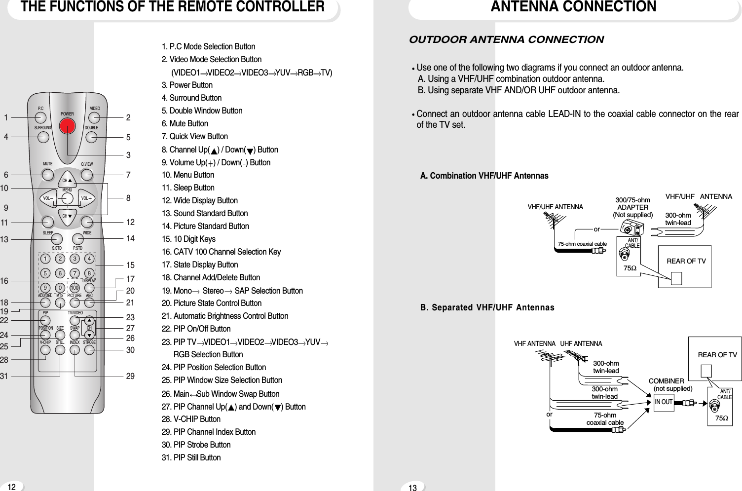
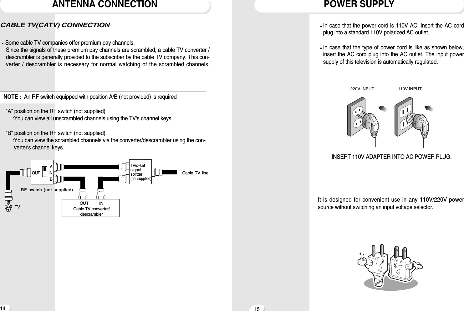
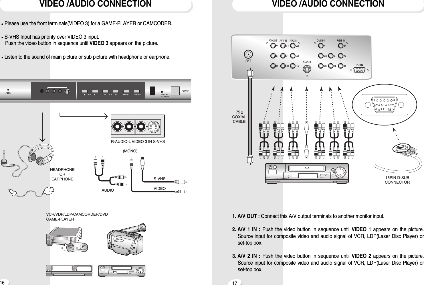
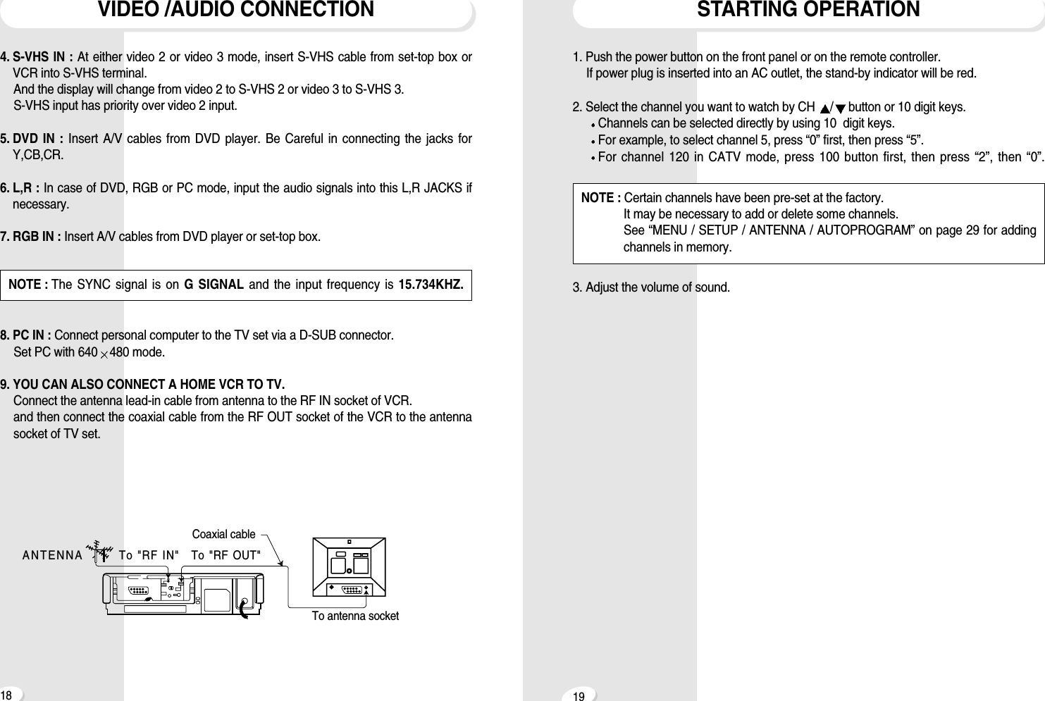
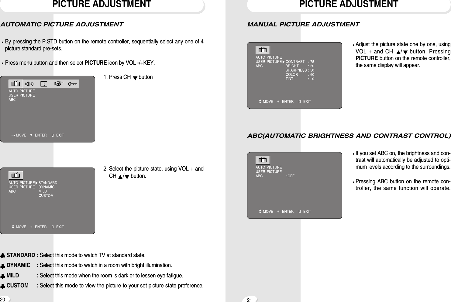
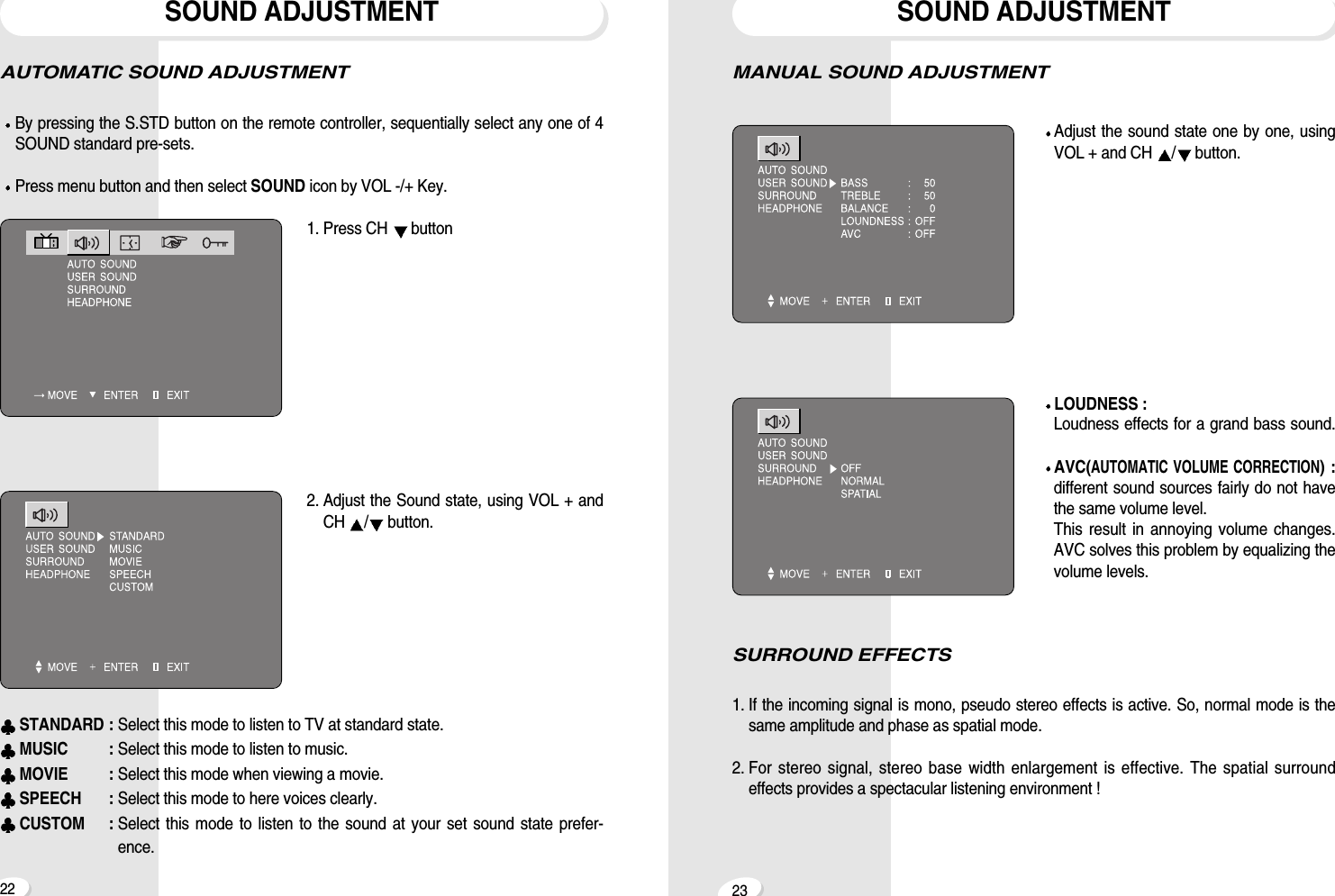
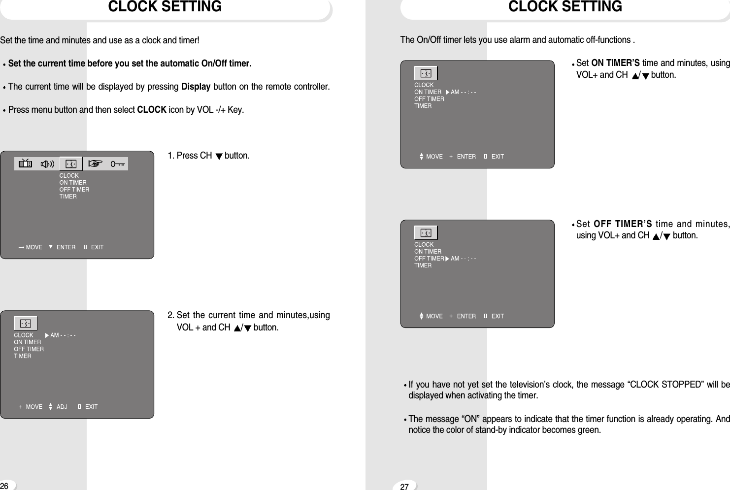
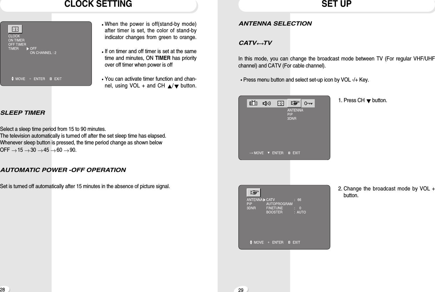
![2524SOUND ADJUSTMENTSTEREO SOUND SYSTEMWhen the power is switched on or channel changes, “ [[S]], ]” symbols are automati-cally displayed, depending on the current broadcast signal.If the receiving signal is weak, noise may be heard.In such case, press MTS button and set the sound mode mono for better sound recep-tion.SOUND ADJUSTMENTHEADPHONEAdjust the volume of sound by VOL + andCH /button.STEREO SOUND SYSTEMThis TV has a built-in BTSC system(ZenithDBX System) decoder to receive stereobroadcast and SAP(Secondary AudioProgram) such as a bilingual broadcast.Whenever MTS button is pressed, the reception mode will change as below. MONO STEREO SAPThe “ [[S]], ] ” symbols indicate that a broadcasting station is transmitting a multiplexsound broadcast. [[S]] STEREO SYMBOL] SAP SYMBOL](https://usermanual.wiki/KTV-Global/29GG.User-manual-1of-3/User-Guide-229838-Page-13.png)