KTV Global LT64BD FM Transmitter User Manual
KTV Global Corporation FM Transmitter
UserManual.wiki
>
KTV Global
>
LT64BD User Manual
USER MANUAL
Navigation menu
Upload a User Manual
Namespaces
Wiki Guide
HTML
PDF
Info
Views
User Manual
Discussion / Help
Navigation
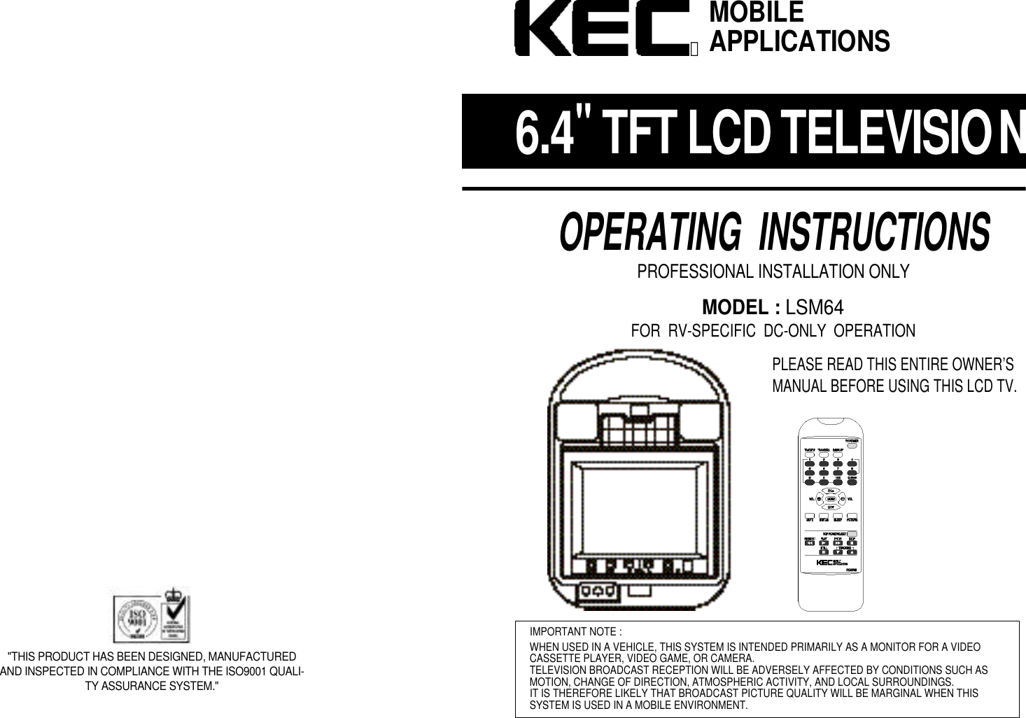
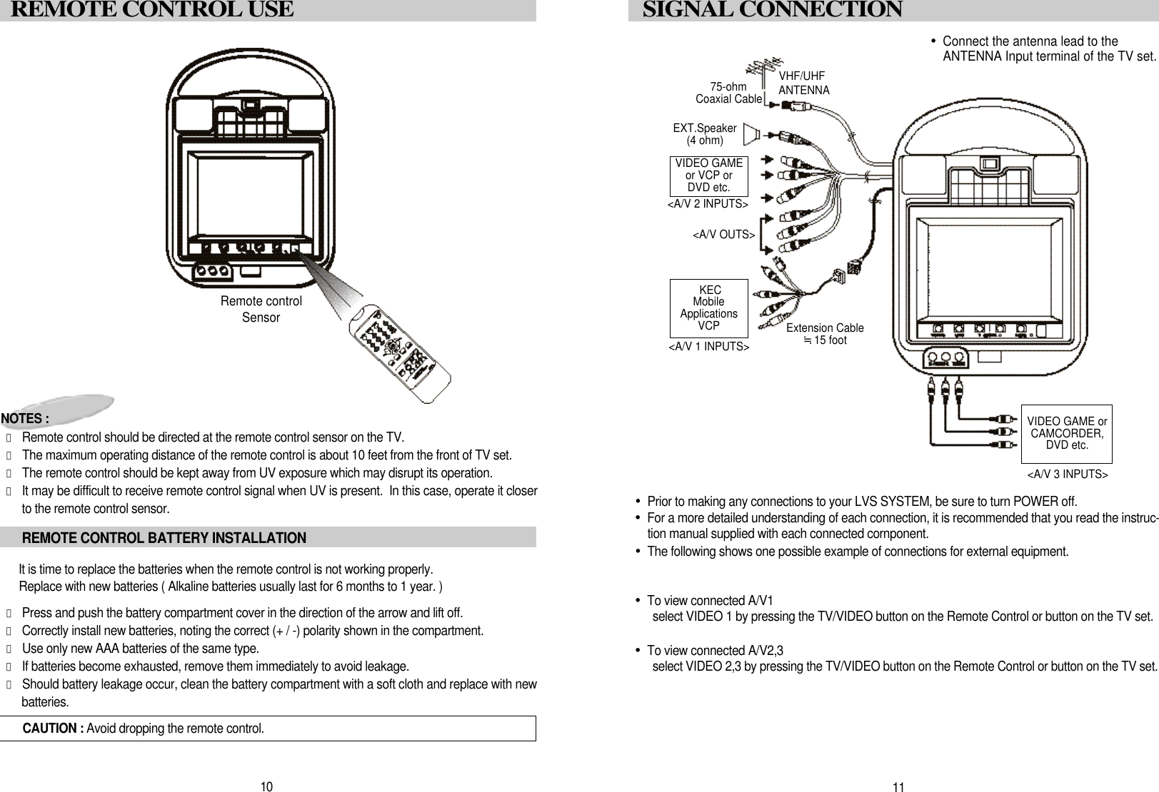
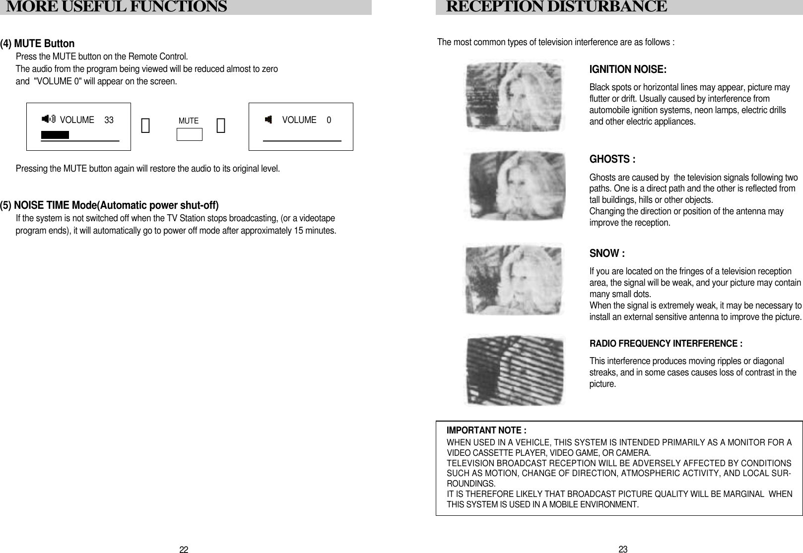
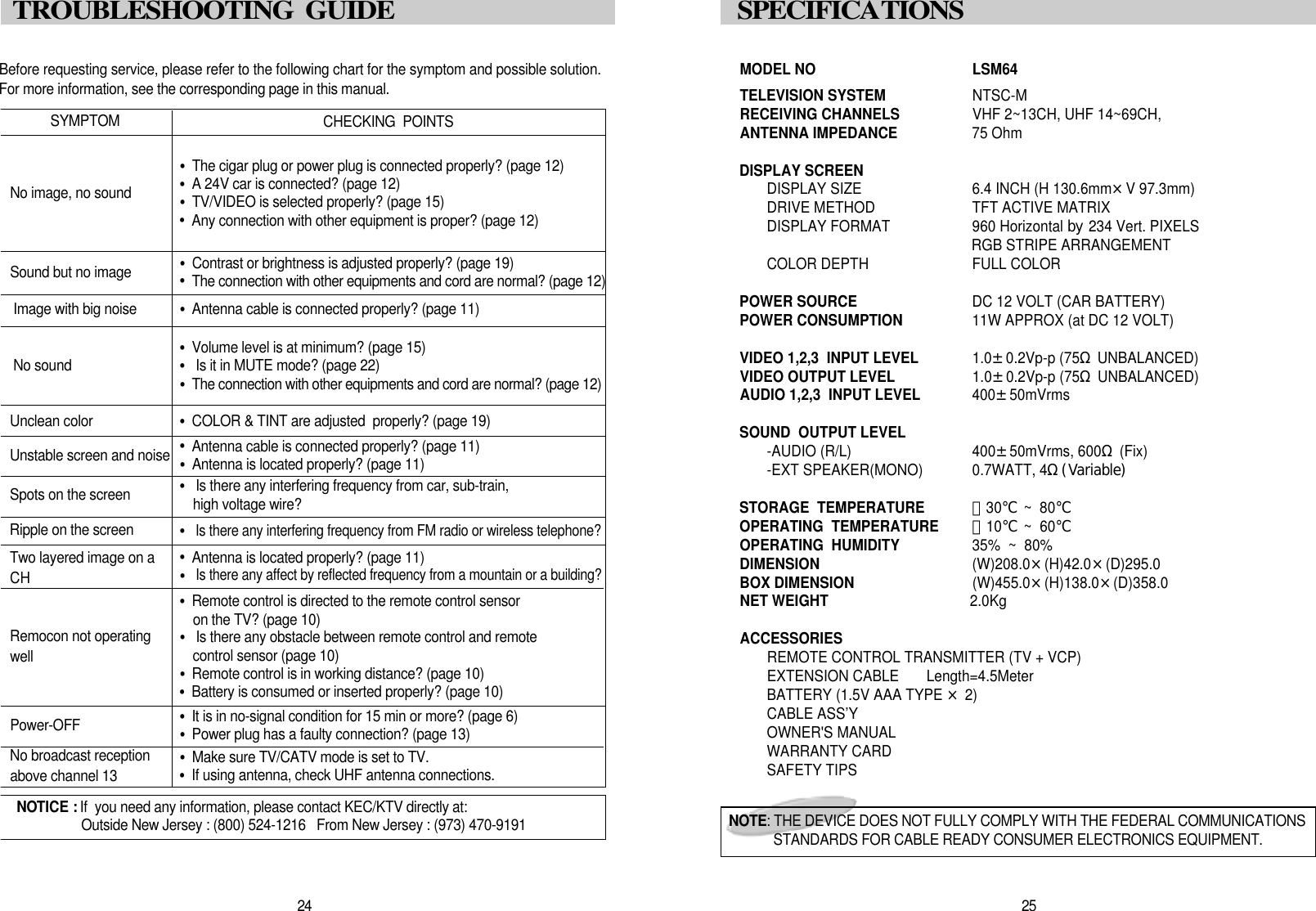
![1 3DOME LIGHT CONNECTION(1) “NEGATIVE” Type Door CircuitRed wire - 12 volt constant power.Brown wire - Chassis ground.This wire provides a ground to the dome light circuit when the three (3) position switch isin the “on” position. If this wire is not connected the dome light will not operate when theswitch is in the “on” position. White wire - Negative door switch.This wire connects to the negative door switch. This wire should be locate in the headliner where the factory dome light was removed. When one of the doors are opened onthe vehicle this wire will have continuity (shorted) to ground.(2) “POSITIVE” Type Door CircuitRed wire - Chassis ground.Brown wire - 12 Volt constant power.A constant power lead may have to be run up to the head liner area for this connection.Check all wires for constant power that were attached to the factory dome light.White wire - Positive door switch.This wire attaches to the positive door switch wire. This wire should be located in thehead liner area where the factory dome light was removed. When one of the doors areopened on the vehicle this wire will have 12 volt power on it. AUDIO SYSTEM•Audio output is Monophonic when receiving on-air broadcast signals.•Audio output is Stereo when a stereo audio signal is fed from external audio equipment that is con-nected to the [selected] A/V1 or A/V2, A/V3 Input terminals.•The SPEAKER JACK teminal is a high level output whose sound level is Variable up to 0.7W max-imun when connected to a 4-ohm speaker.VIDEO SYSTEM•This model incorporates 3sets of AUDIO/VIDEO INPUTS (A/V1 & A/V2, A/V3 for direct connectionof 3 external program sources (Video Game, Camcorder, Video Player, etc.).•Direct connection results in superior video quality from the connected program sources.•Refer to the instruction manual supplied with each external instrument for details.1 2SIGNAL CONNECTIONPOWER CONNECTIONCONNECTING TO CAR POWERNOTE : The cable assembly used to connect the L,M64 to the 12-Volt power supply variesdepending on product packaging.NOTE MANUFACTURER : TEASUNG ELECTRIC CO.,LTD. TYPE# : AWM STYLE 1015W A R N I N GThe DC Battery Cord is ONLY for use with this model.Do not use it to power any other productF R O M RED : DC12VCAR BATTERY BLACK : GROUNDPOWER ConnectionsRED : +12V DCBLACK : GROUNDRed, Brown, White and LeadsThese leads provide power for the dome light circuit. The LSM64 is configured to beused with vehicles that use a “negative” type door dircuit. However, the LSM64 can bereconfigured for vehicles that use a “positive” type door circuit. Most import anddomestic vehicles utilize a “negative” circuit. Ford and Lincoln/Mercury vehicles areusually “positive” type circuits. Check your specific vehicle for the type of circuit it uti-lizes before proceeding with the installation.](https://usermanual.wiki/KTV-Global/LT64BD/User-Guide-134453-Page-7.png)