KZ Broand Technologies AM4000D12 LTE Outdoor CPE User Manual LTE AM4000D B12 17
KZ Broadband Technologies, Ltd. LTE Outdoor CPE LTE AM4000D B12 17
Contents
- 1. User Manuel
- 2. User Manual
User Manual
AirMaster 4000D B12/17 LTE Outdoor CPE
User Manual
Page 2
Table of Contents
1.OVERVIEW ............................................................................................................................................... 4
1.1.USER INTERFACE SPECIFICATION ............................................................................................................ 4
1.2.LTE INTERFACE SPECIFICATION .............................................................................................................. 4
2.GETTING STARTED ................................................................................................................................ 4
2.1.PACKING LIST AND CPE UNIT ................................................................................................................. 4
2.2.INSTALLING THE EQUIPMENT .................................................................................................................. 5
Device logic connection ......................................................................................................................... 5
Installing Outdoor Unit (ODU) ............................................................................................................. 6
3.RF SIGNAL ADJUSTING ........................................................................................................................ 8
RF Signal Adjusting ............................................................................................................................... 8
Wireless Link Status ............................................................................................................................... 8
LED Display .......................................................................................................................................... 9
4.MANAGING CPE DEVICE ..................................................................................................................... 9
WEB GUI Login ..................................................................................................................................... 9
Device Status ........................................................................................................................................ 10
5.DEVICE RESET ...................................................................................................................................... 13
6.FAQ AND TROUBLESHOOTING ........................................................................................................ 13

Page 3
PLEASE READ THESE SAFETY PRECAUTIONS!
RF Energy Health Hazard
The radio equipment described in this guide uses radio frequency transmitters. Although
the power level is low, the concentrated energy from a directional antenna may pose a
health hazard. Do not allow people to come in close proximity to the front of the antenna
while the transmitter is operating.
Protection from Lightning
Before connecting this instrument to the power line, make sure that the voltage of the
power source matches the requirements of the instrument. The unit must be standards.
Disposal and Recycling Information
Pursuant to the WEEE EU Directive electronic and electrical waste must not be disposed of
with unsorted waste. Please contact your local recycling authority for disposal of this
product.
Reduction of Hazardous Substances
This CPE is compliant with the EU Registration, Evaluation, Authorization and Restriction
of Chemicals (REACH) Regulation (Regulation No 1907/2006/EC of the European
Parliament and of the Council) and the EU Restriction of Hazardous Substances (RoHS)
Directive (Directive 2002/95/EC of the European Parliament and of the Council).
FCC Notice, USA
The Airstream CPE units complies with Part 15 of the FCC Rules. Operation is subject to the
following two conditions:
(1) This device may not cause harmful interference, and (2) this device must accept any interference
received, including interference that may cause undesired operation.
NOTE 1: This equipment has been tested and found to comply with the limits for a Class B digital
device, pursuant to part 15 of the FCC Rules. These limits are designed to provide reasonable
protection against harmful interference in a residential installation. This equipment generates, uses
and can radiate radio frequency energy and, if not installed and used in accordance with the
instructions, may cause harmful interference to radio communications. However, there is no guarantee
that interference will not occur in a particular installation. If this equipment does cause harmful
interference to radio or television reception, which can be determined by turning the equipment off
and on, the user is encouraged to try to correct the interference by one or more of the following
measures:
- Reorient or relocate the receiving antenna.
- Increase the separation between the equipment and receiver.
-Connect the equipment into an outlet on a circuit different from that to which the receiver is
connected.
-Consult the dealer or an experienced radio/TV technician for help.
NOTE 2: Any changes or modifications to this unit not expressly approved by the party responsible
for compliance could void the user's authority to operate the equipment.
FCC Radiation Exposure Statement
Page 4
This equipment complies with FCC radiation exposure limits set forth for an uncontrolled
environment. This equipment should be installed and operated with minimum distance 20cm between
the radiator & your body.
1. Overview
The AM4000D is a high performance 4G LTE outdoor CPE product designed
to enable quick LTE fixed data service deployment to the remote customers. It
provides high data throughput and networking features to end users who need
both bandwidth and quality service in the remote area.
1.1. User Interface Specification
Model Description & User Interface
AM4000D
- Panel antenna: 5dBi
- 1 RJ45 10/100M ETH Port
- PWR, RUN, LAN, SIM, LTE (1-5) LEDs
- 48 VDC PoE supply, ODU Power <12 Watts
- Dimensions: 203 mm (L) × 203 mm (W) × 161 mm (D)
- Weight: < 1.6 Kg
1.2. LTE Interface Specification
Frequency Bands Band 12/17
Radio Access 3GPP LTE Release9
Operation Mode FDD, 2RX, 1TxD, DLMIMO
Output Power 23dBm at antenna port
Throughput Category 4
SIM Support SIM card slot (2FF)
2. Getting Started
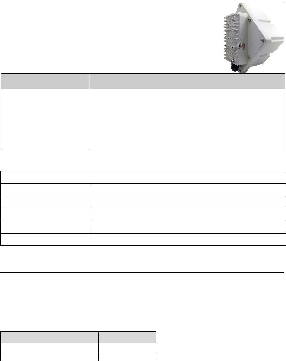
2.1. Packing list and CPE Unit
Upon receiving the product, please unpack the product package carefully. Each product is shipped
with the following items:
Table 2-1 Packing List
Outdoor CPE Products Quantity
CPE Main Unit 1
PoE Power Adapter 1
Page 5
Power Cord 1
Mounting brackets 1
PC Ethernet Cable 1
If you find any of the items missed, please contact your local distributor immediately.
CPE Packing List:
Please unpack the package and check the unit for the following items.
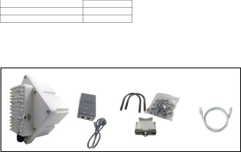
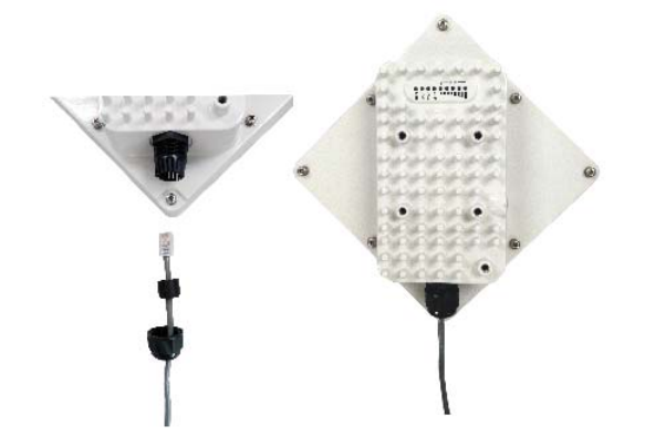
2.2. Installing the Equipment
Device logic connection
For outdoor CPE product, it is preferred that the CPE device be installed in a shaded area to avoid
direct sun light exposure which may cause over heat in certain extreme weather condition. The CPE
should be properly grounded for proper protection against lighting or power surge.
To power on the device, the outdoor CPE must use a 48V PoE integrated DC power supply adapter.
The power adapters can operate in 100-250V AC range and therefore can be used in different country.
Once the device is powered up, the user should wait for about 2 minutes before the device becomes
operational. For CPE with the RUN LED indicator, the LED will stop fast flashing when the CPE
completes the startup procedure.
To connect PC, LAN switch or other type of IP device to the CPE product, the user should use
standard CAT5 Ethernet cable and connect to the appropriate LAN port. Once connect the CPE LAN
LED indicator should come on.
Page 6
Installing Outdoor Unit (ODU)
Mounting Bracket:
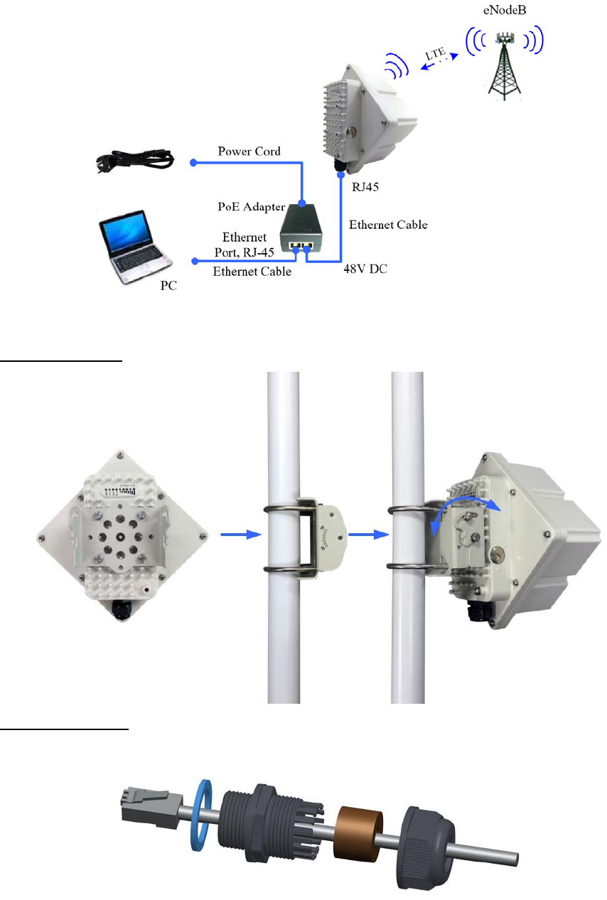
Header Connection:
Page 7
Page 8
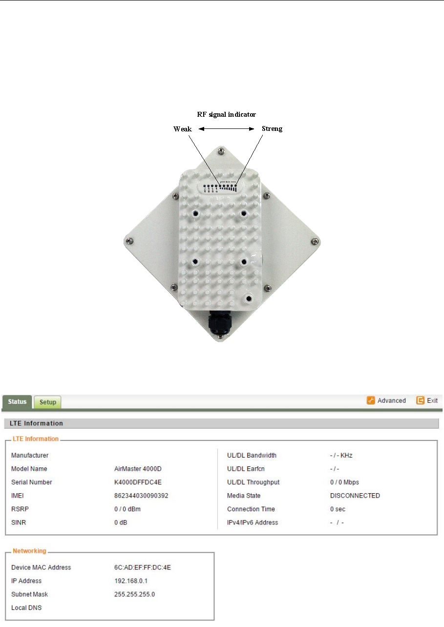
3. RF Signal Adjusting
RF Signal Adjusting
After the CPE outdoor unit has installed, the direction of antenna’s azimuth and pitch angle needs to
adjust for the best signal strength. In near line of sight condition, the CPE will have the best signal
when the antenna is directly pointing the base station.
User can adjust the holder to change the direction and angle of the antenna while observing the RF
LED on the outdoor unit which indicates the signal strength.
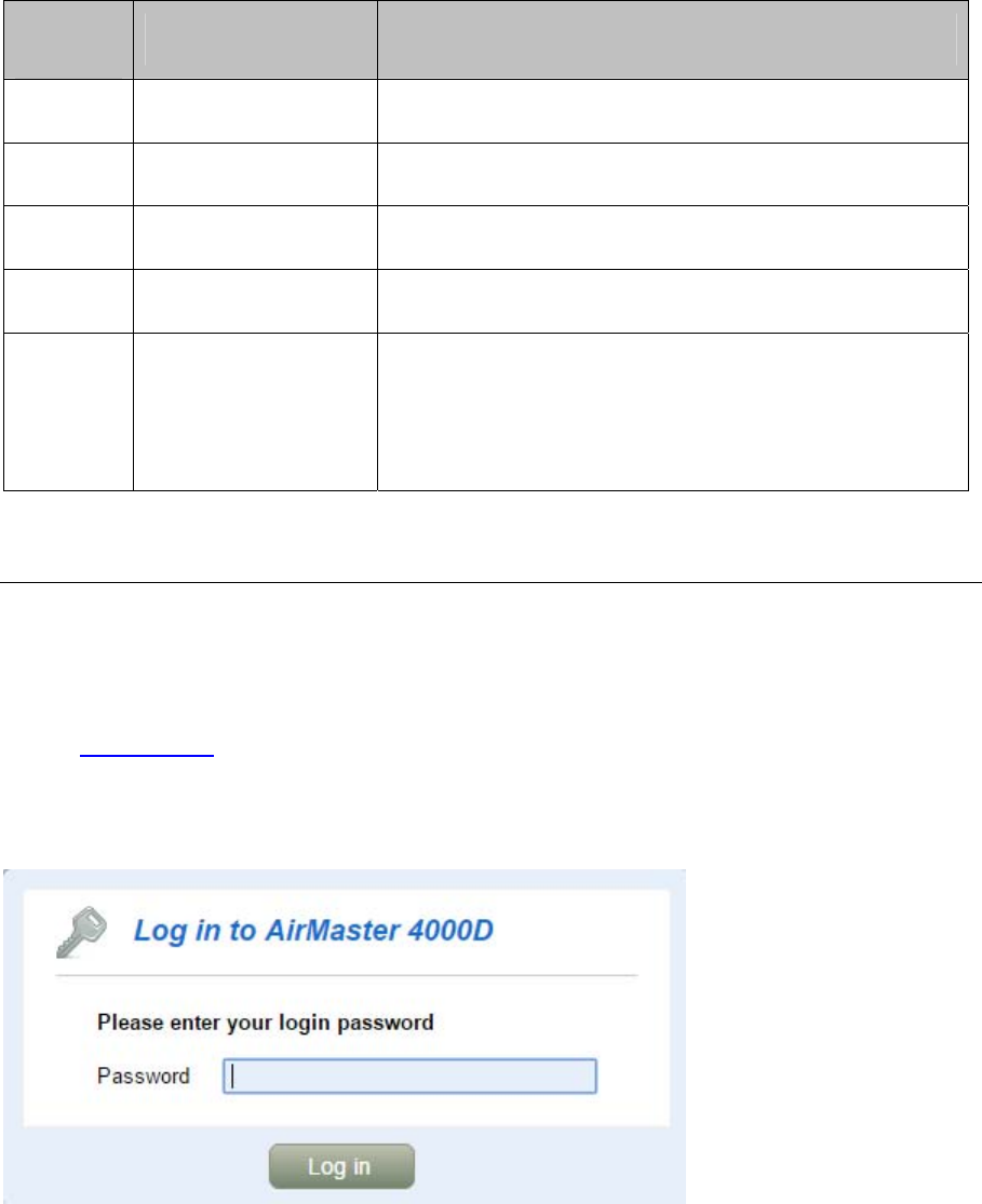
Wireless Link Status
The user can further view more detailed wireless link through the WEB GUI interface under the
device status link. The following wireless link information can be displayed.
Page 9
LED Display
LED
Indicator Function Description
PWR Power Indicator Green Color – Device is powered on
RUN System Run Indicator Fast Blinking – Device is rebooting
Solid Green – Device is in normal operation
LAN LAN port status Solid Green – LAN port is up
Blinking Green – LAN data activity in progress
SIM SIM Card Indicator Light is on – SIM card state ready.
RF(5LEDs) RF Signal Strength
5 level signal strengths indication by 5 green LEDs
1 green LED: RSRP<= -118dBm
2 green LEDs: -118dBm <=RSRP< -105dBm
3 green LEDs: -105dBm<=RSRP< -95dBm
4 green LEDs: -95dBm<=RSRP< -85dBm
5 green LEDs: -85dBm<=RSRP
4. Managing CPE Device
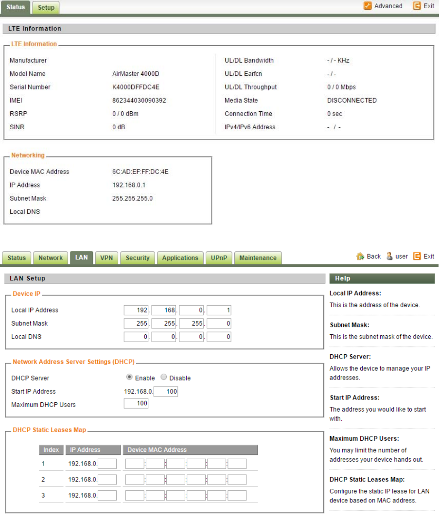
WEB GUI Login
It is a preferred to setup the CPE using a Web browser from a local PC connected to CPE LAN port.
The user should ensure that the connected PC acquired IP address via DHCP from the device. After IP
connectivity is established between the PC and CPE device, the user may launch a Web browser and
specify http://10.1.1.1 in the address bar. A window will pop up requesting password. Input the user
login password and then click the “Log in” button. After successful log on, the default home page of
the WEB GUI interface will appear. Note that the default user password is “user123”. The admin
password is protected and only available to the network operator.
Page 10
Device Status
Once the user is logged in, the following window device status window will be prompted for viewing.
It contains both the wireless link information, networking and device information configured for the
device. For wireless info gives quite detailed information about the radio connection and user can use
it to determine the receiving signal strength and transmit power of the device.
LAN Configuration
The LAN setting allows user to specify the DHCP server setting for the LAN devices including the
pool address, IP and MAC binging and whether DHCP server should be enabled.
User is advised to leave the default setting unchanged for quick configuration and smooth device
Page 11
operation.
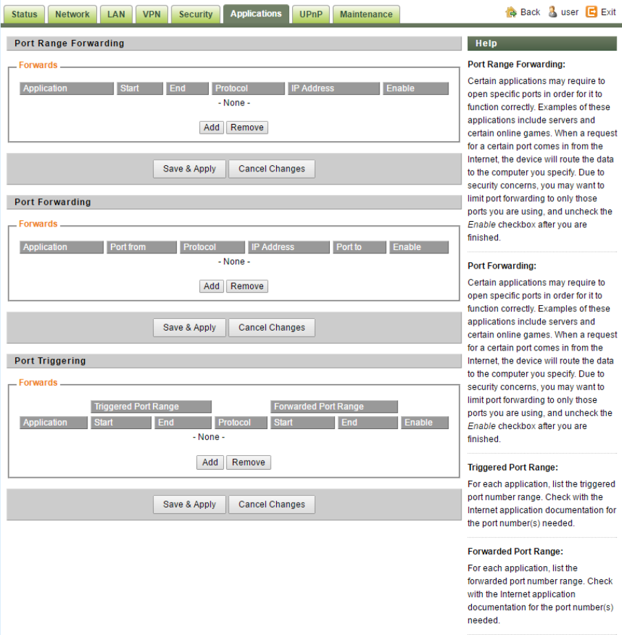
Applications Configuration
Port Range Forwarding:
Certain applications may require to open specific ports in order for it to function correctly. Examples
of these applications include servers and certain online games. When a request for a certain port
comes in from the Internet, the device will route the data to the computer you specify. Due to security
concerns, you may want to limit port forwarding to only those ports you are using, and uncheck the
Enable checkbox after you are finished.
Port Forwarding:
Certain applications may require to open specific ports in order for it to function correctly. Examples
of these applications include servers and certain online games. When a request for a certain port
comes in from the Internet, the device will route the data to the computer you specify. Due to security
Page 12
concerns, you may want to limit port forwarding to only those ports you are using, and uncheck the
Enable checkbox after you are finished.
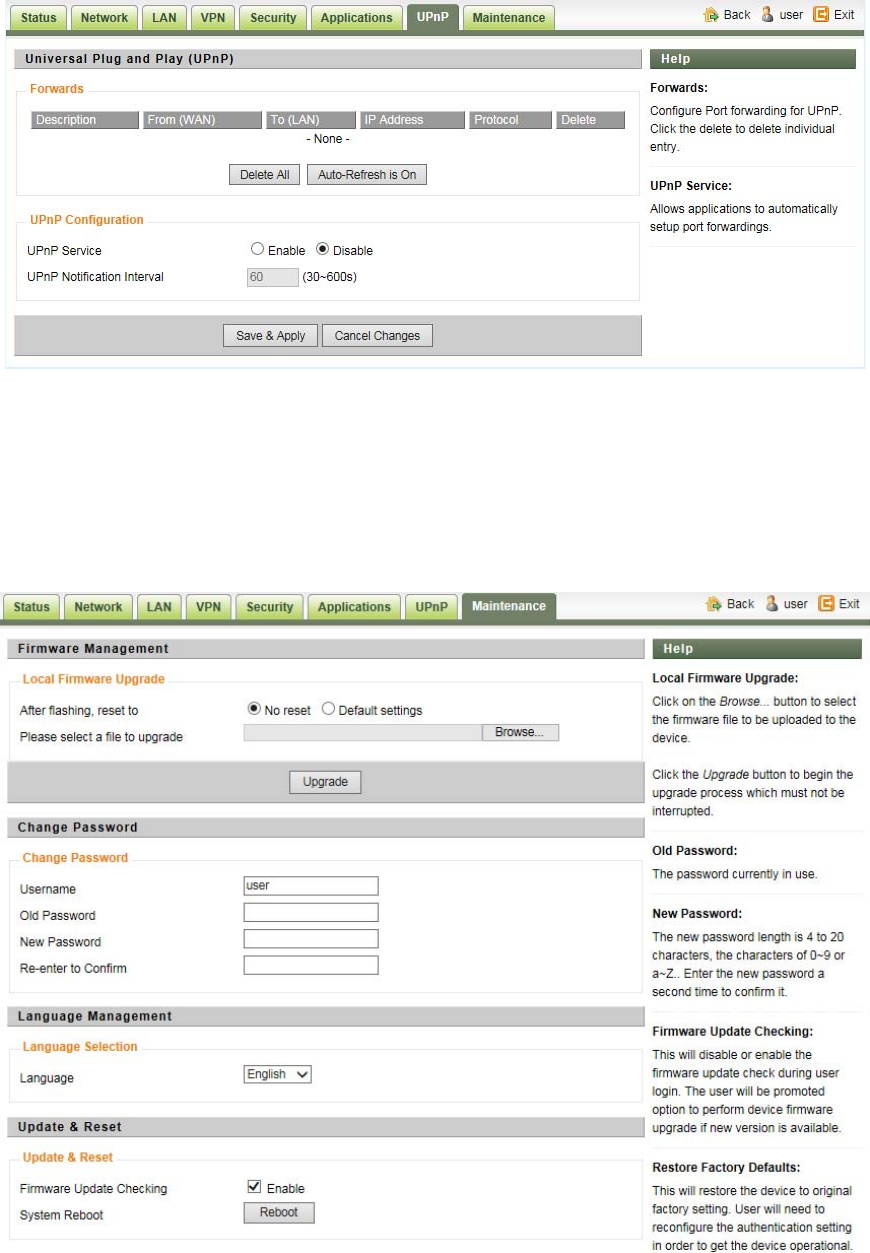
UPnP Setting
Forwards:
Configure Port forwarding for UPnP. Click the trash sign to delete individual entry.
UPnP Service:
Allows applications to automatically setup port forwarding.
Maintenance

Page 13
Firmware Upgrade over HTTP:
Click on the Browser button to select the firmware file to be uploaded to the device.
Click the Upgrade button to begin the upgrade process. Upgrade must not be interrupted.
Old Password:
The password currently in use.
New Password:
The new password must not exceed 63 characters in length and must not include any spaces. Enter the
new password a second time to confirm it.
Firmware Update Checking:
This will disable or enable the firmware update check during user login. The user will be promoted
option to perform device firmware upgrade if new version is available.
Restore Factory Defaults:
This will restore the device to original factory setting. User will need to reconfigure the authentication
setting in order to get the device operational.
System Reboot:
Click the Reboot button to restart the device.
5. Device Reset
In case the user forgets the login password, a reset password can be obtaining from the operator by
given the device MAC address. The user can enter the reset password in the login window and a
system reset will be performed and the unit will be rebooted. The user can then be allowed to use the
original default login password to gain access to the unit WEB GUI again.
After factory reset, the device may need to be reconfigured by the user or even operator to gain
network access. This is not a recommended operation and special care must be taken to ensure the
device will be properly re-configured after factory reset.
6. FAQ and Troubleshooting
1) My PC cannot connect to the CPE.
Re-plug the PC Ethernet cable and check if the PC LAN connection is up or showing activity.
Check if the system run LED is on. If it is not, check the power cord and make sure it is
connected properly. Also verify that the AC power supply is available.
If the PC LAN shows no activity and system run LED is off but the power cord is connected
properly and there is AC supply, then it is likely the adapter is damaged. Please contact
distributor to obtain replacement part.
2) My PC cannot acquire IP from the CPE.
First check if the Network card is up and working properly. Then check the PC NIC
Page 14
configuration and make sure the DHCP is enabled.
To release and renew the correct IP address, please unplug the Ethernet cable from PC and
wait for about 5 seconds, then connect it again.
If the problem persists, please contact the operator or distributor for further diagnose.
3) My CPE networking is not working properly.
You may want to check if the LTE connection is up and running properly. You can do this by
login the WEB GUI and check the LTE Interface Info page.
You may want to perform a factory reset and see if the problem is being corrected. You can do
this by log into the WEB GUI perform restore the unit to default factory setting.
If the problem cannot be corrected by factory reset, please contact the operator or distributor
for further diagnose.
4) I forget the login password and like to reset the unit to factory default.
Please contact the operator or distributor and give them the IMEI number of the unit. The
operator or distributor can issue you a RESET password for you to enter in the WEB login
window.
After the unit is reset to factory default, you can login using the default password.