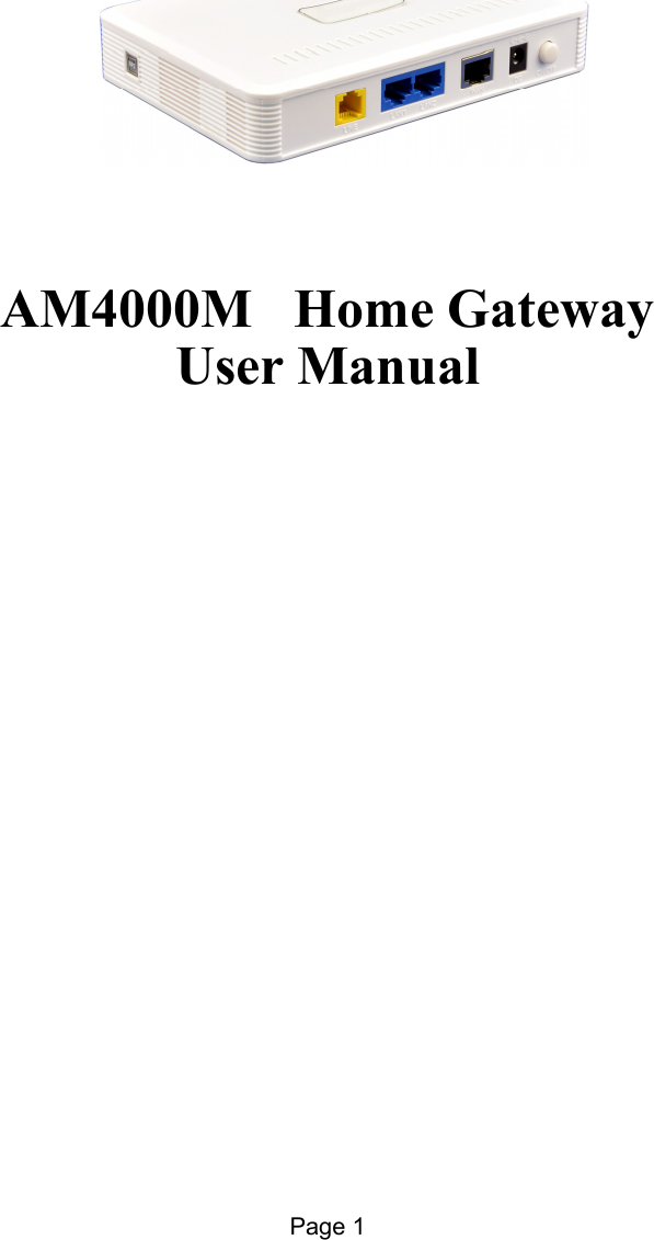
KZ Broand Technologies AM4000MHGW Home Gateway User Manual LTE AirMaster4000M

KZ Broadband Technologies, Ltd. Home Gateway LTE AirMaster4000M

Users Manual

Page 1                  AM4000M   Home Gateway  User Manual
Page 2   PLEASE READ THESE SAFETY PRECAUTIONS! RF Energy Health Hazard     The radio equipment described in this guide uses radio frequency transmitters. Although the power level is low, the concentrated energy from a directional antenna may pose a health hazard. Do not allow people to come in close proximity to the front of the antenna while the transmitter is operating. Protection from Lightning     Before connecting this instrument to the power line, make sure that the voltage of the power source matches the requirements of the instrument. The unit must be standards. Disposal and Recycling Information Pursuant to the WEEE EU Directive electronic and electrical waste must not be disposed of with unsorted waste. Please contact your local recycling authority for disposal of this product. Reduction of Hazardous Substances This CPE is compliant with the EU Registration, Evaluation, Authorization and Restriction of Chemicals (REACH) Regulation (Regulation No 1907/2006/EC of the European Parliament and of the Council) and the EU Restriction of Hazardous Substances (RoHS) Directive (Directive 2002/95/EC of the European Parliament and of the Council).  FCC Notice, USA This device complies with Part 15 of the FCC Rules. Operation is subject to the following two conditions: (1) This device may not cause harmful interference, and (2) this device must accept any interference received, including interference that may cause undesired operation.  NOTE 1: This equipment has been tested and found to comply with the limits for a Class B digital device, pursuant to part 15 of the FCC Rules. These limits are designed to provide reasonable protection against harmful interference in a residential installation. This equipment generates, uses and can radiate radio frequency energy and, if not installed and used in accordance with the instructions, may cause harmful interference to radio communications. However, there is no guarantee that interference will not occur in a particular installation. If this equipment does cause harmful interference to radio or television reception, which can be determined by turning the equipment off and on, the user is encouraged to try to correct the interference by one or more of the following measures: - Reorient or relocate the receiving antenna. - Increase the separation between the equipment and receiver. -Connect the equipment into an outlet on a circuit different from that to which the receiver is connected. -Consult the dealer or an experienced radio/TV technician for help.  NOTE 2: Any changes or modifications to this unit not expressly approved by the party responsible for compliance could void the user's authority to operate the equipment. FCC Radiation Exposure Statement: This equipment complies with FCC radiation exposure limits set forth for an uncontrolled environment. This equipment should be installed and operated with minimum distance 20cm between the radiator & your body.
Page 3   Table of contents   1.OVERVIEW ............................................................................................................................................... 41.1USER INTERFACE SPECIFICATION ............................................................................................................ 41.2WI-FI INTERFACE(IDU) .......................................................................................................................... 42.GETTING STARTED ................................................................................................................................ 42.1PACKING LIST AND CPE UNIT ................................................................................................................. 42.2INSTALLING THE EQUIPMENT .................................................................................................................. 5Device logic connection ......................................................................................................................... 5LED Display .......................................................................................................................................... 63.MANAGING CPE DEVICE ..................................................................................................................... 63.1WEB LOGIN—172.16.1.1 ...................................................................................................................... 63.2SYSTEM STATUS DISPLAY ....................................................................................................................... 63.3NETWORK CONFIGURATION ....................................................................................................................  7Modify MTU Size ................................................................................................................................... 73.4WI-FI CONFIGURATION-MODIFY SSID/SECURITY .................................................................................. 8WPS setting ............................................................................................................................................ 93.5SERVICE CONFIGURATION-DMZ SETTING .............................................................................................. 93.6VOIP CONFIGURATION-SIP ACCOUNT SETTING..................................................................................... 103.7SYSTEM MAINTENANCE ........................................................................................................................  11Telnet Enable all and modify password ............................................................................................... 11TR069 Configuration ........................................................................................................................... 11Firmware Upgrade over HTTP ............................................................................................................ 13Load Factory Default ........................................................................................................................... 134.HARDWARE RESET .............................................................................................................................. 145.FAQ AND TROUBLESHOOTING ........................................................................................................ 14
Page 4   1. Overview AM4000M is an indoor multiservice gateway unit (IDU) that supports advanced networking, VoIP gateway and WLAN AP functionalities. It enables wide service coverage and provides high data throughput and networking features to customers who needs easy broadband access, low cost VoIP service and Wi-Fi connectivity.  1.1 User Interface Specification Model  Description & User Interface AM4000M -  1 RJ45 10/100M ETH (PoE),2 RJ45 10/100M ETH,1 RJ11/FXS Line -  Power, NET, Wi-Fi, LAN1-2, LINE, WPS -  24V/1.0A DC -  Dimensions: 135 mm (L) × 105 mm (W) × 30mm (D) -  Weight:  < 300g 1.2 Wi-Fi Interface(IDU) Radio Access  802.11b/g/n (300 Mbps) Output Power  15 1dBm Antenna 3dBi built-in antenna Security  64/128 bit WEP, WPA/WPA2 2. Getting Started   2.1 Packing list and CPE Unit Upon receiving the product, please unpack the product package carefully. Each product is shipped with the following items:  Table 2-1 Packing List  Products  Quantity IDU unit  1 24V DC Power adapter  1 PC Ethernet Cable  1 If you find any of the items is missing, please contact our local distributor immediately.
Page 5   CPE Unit: Unpacking the Equipment Table 2-1 lists all the standard parts that are supplied in your LTE CPE Unit Installation Package. Please take the time to unpack the package and check its contents against this list.  2.2 Installing the Equipment   Device logic connection AM4000M is user-friendly and easy to setup. To power on the IDU device, the IDU must uses a 24V DC power supply adapter. The power adapters can operate in 90-250V AC range and therefore can be used in different countries. Once the IDU device is powered up, the user should wait for about 2 minutes before the device becomes operational.  To connect PC, LAN switch or other type of IP device to the product, the user should use standard CAT5 Ethernet cable and connect to the appropriate LAN port of the IDU. Once connect the CPE LAN LED indicator should come on.  To use the phone service, user can simply plug the phone line to the CPE RJ11 port in the back. If the line is not registered or configured, a fast busy tone will be provided and the corresponding LINE LED light will be off.
Page 6    LED Display LED Indicator LED Indicator  Function  Description AM4000M PWR  Power Indicator   Orange Color – Device is power on and booting Green Color – Device at work NET WAN Indicator  OFF – NO wireless network access. Blinking Green – WAN data transmission in progress. WLAN  Wi-Fi status indicator  Green Light is on –Wi-Fi is enabled and working LAN  LAN port status OFF – No LAN cable connected Solid Green – The LAN port is up Blinking Green – LAN data transmission in progress Vo i c e   POTS line status indicator OFF – Line is not registered or provisioned. Green Color – The line is ready and registered Green Blinking – Voice Call in progress WPS  WPS Service Access  Blinking Orange – Device WPS at work Note: WAN port can also provide the POE power supply. 3. Managing CPE Device The AM4000M offers rich management features which facilitate the task of service provider. It supports local management access, Telnet, WEB, and centralized remote OTA configuration, upgrades management and device monitoring via standard TR-069 ACS systems. 3.1 WEB Login—172.16.1.1 It is a preferred to setup the CPE using a Web browser from a local PC connected to device LAN port. The user should ensure that the connected PC had acquired IP address via DHCP from the device. After IP connectivity is established between the PC and CPE device, the user may launch a Web browser and specify  http://172.16.1.1 in the address bar. A window will pop up requesting password. Input the user login password and then click the “Log In” button. After successful log on, the default home page of the WEB GUI interface will appear. Note that the default user password is “admin123”.  3.2 System Status Display Once the user is logged in, the following window System status window will be prompted for viewing. It contains the System Status, WAN link information, Network Configuration, Wi-Fi Configuration, VoIP Configuration and System Management.
Page 7    3.3 Network Configuration  Modify MTU Size The default Operation Mode is Router, and the PC of the user that connected to device LAN port will obtain IP address via DHCP server of the device. The default MTU Size is 1500, user can modify the MTU Size if necessary.
Page 8    Note: After configure any parameters to the device, you must click the “Apply””Save & Commit “button to save the configuration otherwise the configuration will not take effect. 3.4 Wi-Fi Configuration-Modify SSID/Security In Wi-Fi configuration, the user can modify the default SSID and select the desired Security Policy to protect device Wi-Fi access. For easy configuration, the user can use one of the following three common security policies for setup.  WPA-PSK / WPA2-PSK      The most commonly used standard Wi-Fi Security policy.   For all the configuration changes to take effect, the user is required to click on the “apply” button to save the configuration. Click on the “Save & Commit” button to complete the parameters setup and begin to use the device.
Page 9     WPS setting When a quick and convenient access to connect is needed, the WPS function is useful.  3.5 Service Configuration-DMZ Setting By enabling this option will make the specified local LAN host (DMZ IP) was exposed to the Internet, all ports can be accessed by other computers on the Internet.
Page 10   3.6 Voip Configuration-SIP Account Setting In this configuration page, the user requires to enter the SIP user name, account and password information if he desires to configure the VoIP networking. And the register status must to enable, the register server IP also requires to configure. The SIP server configuration will be performed by the network operator via admin management. The SIP account status is displayed for user information. When the SIP line is registered and ready, the LINE LED in the front panel will be light up.  If the device VoIP function is not working properly, the user is advised to contact the network operator for assistance.   It would show “register success” of the Port Status after register succeed.
Page 11   3.7 System Maintenance WEB GUI menu to configure the device in more details (see diagram below). The configuration is easy to use and self explanatory.  You can select the language or modify the web login password via the General Setting page.  Telnet Enable all and modify password You can also set Telnet Management as Enable All for all the users, include WAN user, LAN user and the Wireless station to telnet to the CPE.  cmd shell and run command: telnet 172.16.1.1 Login: admin   Password: root123  TR069 Configuration After enable the tr069 management in the General Setting page, you must also configure the validity acs url for monitoring the device via standard TR-069 ACS systems.
Page 12
Page 13    Firmware Upgrade over HTTP Click on the Browser button to select the firmware file to be uploaded to the device. Click the” Apply” button to begin the upgrade process.   Please do not interrupt the upgrade process and continue to wait for the following pop window to appear, then Restore Defaults and Reboot.   Load Factory Default Click the “Load Default” button will restore the device to original factory setting. User will need to reconfigure the authentication setting in order to get the device operational.
Page 14   4. Hardware Reset In case the user forgot the login password, the device can be reset by pressing (using a pin) the reset button next to the LAN port for 10 seconds and then wait for the CPE to reboot and complete the restart. The user can then be allowed to use the original default login password to gain access to the unit WEB GUI again.  After factory reset, the device may need to be reconfigured by the user or even operator to gain network access. This is not a recommended operation and special care must be taken to ensure the device will be properly re-configured after factory reset.   5. FAQ and Troubleshooting  1) My PC cannot connect to the CPE.   Re-plug the PC Ethernet cable and check if the PC LAN connection is up or showing activity.   Check if the system run LED is on. If it is not, check the power cord and make sure it is connected properly. Also verify that the AC power supply is available.   If the PC LAN shows no activity and system run LED is off but the power cord is connected properly and there is AC supply, then it is likely the adapter is damaged. Please contact distributor to obtain replacement part.  2) My PC cannot acquire IP from the CPE.   First check if the Network card is up and working properly. Then check the PC Network card configuration and make sure the DHCP is enabled.  To release and renew the correct IP address, please unplug the Ethernet cable from PC and wait for about 5 seconds, then connect it again.   If the problem persists, please contact the operator or distributor for further diagnose. 3) My CPE networking is not working properly.   You may want to check if the WAN connection is up and running properly. You can do this by login the WEB GUI and check the Interface Info page.  You may want to perform a factory reset and see if the problem is being corrected. You can do this by log into the WEB GUI using “admin” password and perform restore the unit to default factory setting.   If the problem cannot be corrected by factory reset, please contact the operator or distributor for further diagnose. 4) I forget the login password and like to reset the unit to factory default.   The user can hold the RESET button on the reverse side of CPE for 10 seconds to clear and reset the unit to factory default setting.    After the unit is reset to factory default, you can login using the default password.

Navigation menu