Kaba Access Operations Manual E Plex / Power Electronic Pushbutton Lock 2000 Series Installation Instructions Powerplex Pkg3218
E-Plex 2000 / PowerPlex 2000 Series Installation Instructions - PKG3218 e-plex-2000-powerplex-2000-series-installation-instructions-pkg3218 E-Plex 2000 Electronic Pushbutton Lock - Kaba Access & Data Systems
Kaba E-Plex / PowerPlex Electronic Pushbutton Lock - 2000 Series Installation Instructions e-plex-2000-powerplex-2000-series-installation-instructions-pkg3218 Installation Instructions
User Manual: Kaba Access Kaba E-Plex / PowerPlex Electronic Pushbutton Lock - 2000 Series Installation Instructions Installation Instructions
Open the PDF directly: View PDF ![]() .
.
Page Count: 48
E-PLEX®2000 and 2400 Series
PowerPlex 2000 and 2400 Series
INSTALLATION INSTRUCTIONS

2
APPLICABLE FOR UNITED KINGDOM INSTALLATIONS ONLY
It is the responsibility of the installer to ensure that the installation of this product
complies with the relevant regulations applicable to the territory / country (UK only).
K_`jcfZbnXj`eZcl[\[`eXjlZZ\jj]lc]`i\k\jk<E(-*+$( feXk`dY\i[ffi#n_`Z_
i\c`\[fek_\lj\f]`ekld\jZ\ekgifk\Zk`feXj[\kX`c\[Y\cfn%
K_`jgifk\Zk`fedljkY\i\gc`ZXk\[\oXZkcp#kf\ejli\k_Xkk_\g\i]fidXeZ\f]X
j`d`cXi]`i\[ffi`jefkZfdgifd`j\[%
Intumescent gasket requirements for fire doors
Product Fire Door type -
timber or mineral
composite
(to BS EN 1634-1)
Around tubular
latch or
lockcase
Behind forend Behind strike
plate (and any
back box)
Kaba Pack
E-plex 5000
E-plex 5200
E-plex 5700
(_i$,*ddk_`Zb
fi
(
⁄
)
_i$++ddk_`Zb
@ek\i[\ejj_\\k
o(ddk_`Zb
@ek\i[\ejj_\\k
o)ddk_`Zb
@ek\i[\ejj_\\k
o)ddk_`Zb
GXZb(
B898$:PC@E;<I$G8:B$(
E-plex 2000
PowerPlex 2000
(_i$,*ddk_`Zb
fi
(
⁄
)
_i$++ddk_`Zb
@ek\i[\ejj_\\k
o(ddk_`Zb
@ek\i[\ejj_\\k
o)ddk_`Zb
@ek\i[\ejj_\\k
o(ddk_`Zb
GXZb(
B898$:PC@E;<I$G8:B$(
Simplex (L)1000
Simplex 5000
Simplex 6200
Simplex 8100
(_i$,*ddk_`Zb
fi
(
⁄
)
_i$++ddk_`Zb
@ek\i[\ejj_\\k
o(ddk_`Zb
@ek\i[\ejj_\\k
o)ddk_`Zb
@ek\i[\ejj_\\k
o)ddk_`Zb
GXZb(
B898$:PC@E;<I$G8:B$(
Simplex 7100
with tubular
latch
or tubular bolt
(
⁄
)
_i$++ddk_`Zb @ek\i[\ejj_\\k
o(ddk_`Zb
@ek\i[\ejj_\\k
o)ddk_`Zb
@ek\i[\ejj_\\k
o(ddk_`Zb
GXZb)
@KC$B898$.'''$(
;ffikpg\jZfm\i\[Ypk_\k\jk\m`[\eZ\
J`e^c\c\X]fi[flYc\c\X]#j`e^c\XZk`fek`dY\ifid`e\iXcZfdgfj`k\[ffij\kk\jk\[kf<E(-*+$(
D`e`dldc\X]k_`Zbe\jj
-'d`elk\jÅ,*dd
*'d`elk\jÅ++dd
K_\c\Xm\jj_flc[_Xm\_Xi[nff[c`gg`e^jf]d`e`dld-ddk_`Zbe\jjXe[Xd`e`dld[\ej`kpf]-*'b^&d*
K_\[ffi]iXd\f]*'d`elk\[ffij\kjj_XccY\f]jf]knff[fi_Xi[nff[n`k_Xd`e`dld[\ej`kpf]+,'b^&d*
K_\[ffi]iXd\f]-'d`elk\[ffij\kjj_XccY\f]jf]knff[fi_Xi[nff[n`k_Xd`e`dld[\ej`kpf]-*'b^&d*
=fiXcc-'d`elk\Xggc`ZXk`fej#k_\[ffic\X]j_Xcc`eZcl[\efe$ZfdYljk`Yc\jlY$]XZ`e^j

3
TABLE OF CONTENTS
A. Cylindrical Installation . . . . . . . . . . . . . . . . . . . . . . . . . . . . . . . . . . . . . . . . . . . . .4
B. Mortise Installation . . . . . . . . . . . . . . . . . . . . . . . . . . . . . . . . . . . . . . . . . . . . . . . .11
C. Exit Trim Installation . . . . . . . . . . . . . . . . . . . . . . . . . . . . . . . . . . . . . . . . . . . . . .33
D. Installing Outside Lever on Non-Mechanical Override . . . . . . . . . . . . . . . . .37
E. Reversing the Outside Lever for Series Without Mechanical Override . . .37
F. Installing Optional K-I-L Key or Best Removable Core . . . . . . . . . . . . . . . .38
Override and Outside Lever
G. Testing the Operations of the Outside Lever . . . . . . . . . . . . . . . . . . . . . . . .40
H. Testing the Mechanical Key Override with Change Key . . . . . . . . . . . . . . . .41
I. Changing Lock Cylinders . . . . . . . . . . . . . . . . . . . . . . . . . . . . . . . . . . . . . . . . . .42
J. Changing Best-Type Core . . . . . . . . . . . . . . . . . . . . . . . . . . . . . . . . . . . . . . . . .43
K. Removing and Reassembling the Outside Lever . . . . . . . . . . . . . . . . . . . . . .43
L. Installing Rubber Bumpers . . . . . . . . . . . . . . . . . . . . . . . . . . . . . . . . . . . . . . . .44
M. Installing Battery Pack . . . . . . . . . . . . . . . . . . . . . . . . . . . . . . . . . . . . . . . . . . . .44
N. Testing the Operation of the Lock . . . . . . . . . . . . . . . . . . . . . . . . . . . . . . . . . .45
Warranty card . . . . . . . . . . . . . . . . . . . . . . . . . . . . . . . . . . . . . . . .center of book
For technical assistance, call 1-800-849-TECH (8324) or 336-725-1331
Please read and follow all directions carefully.
These instructions are designed for use by maintenance professionals or lock
installers who are familiar with common safety practices and competent to
perform the steps described. Kaba Access Control is not responsible for dam-
age or malfunction due to incorrect installation.
Important: Carefully inspect windows, doorframe, door, etc. to ensure that the
recommended procedures will not cause damage. Kaba Access Control standard
warranty does not cover damages caused by installation.

4
A. CYLINDRICAL
CHECKLIST
Parts and Tools List
Each E-Plex/PowerPlex 2xxx lockset includes:
• Outside lock housing
• Inside lock assembly
• Outside lever
• Gasket for outside lock housing (not for PowerPlex 2000 versions)
• Cylindrical latch
• Cylinder drive unit
• Battery holder with 3 AA batteries (not included in PowerPlex 2000 versions)
• Drilling templates
• Hardware bag, includes:
- Square spindle
- Phillips screw (6-32 x 5⁄16") (not for PowerPlex 2000 versions)
- Strike kit
- (3) mounting screws (12-24, 1⁄8" hex head)
- Allen Key 1⁄8" — Allen Key 5⁄64"
- (2) 1" (25 mm) Phillips mounting screws
- (1) extension spring
- (4) pairs of Flat Head screws 10-24
- (3) spacers
• Key Override (Optional)
- (1) cylinder with 2 keys for override (if equipped)
- (1) cylinder plug (if equipped)
- (1) cylinder cap (if equipped)
- (2) adaptors for best-type cylinders (if equipped)
- (1) override shaft tool (if equipped)
Warning: For E-Plex/PowerPlex 2000 locks, the Master Code of this lock has
been factory preset: 1,2,3,4,5,6,7,8. To activate lock functions, the master
combination must be changed at the time of installation.
For E-Plex 24xx locks, you will have to generate an access code using the web
application to test the lock operation.
5
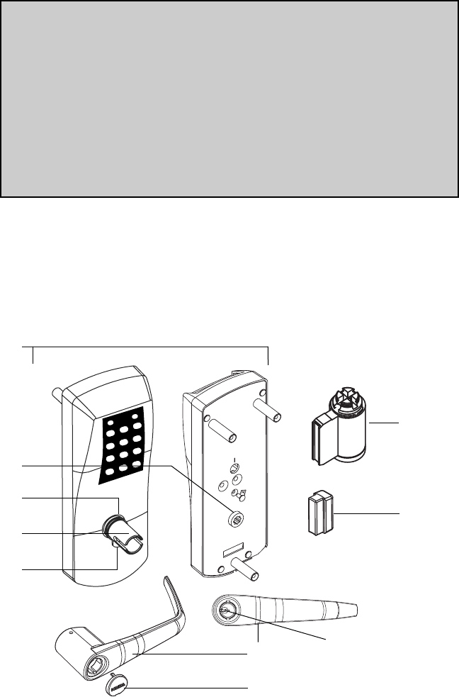
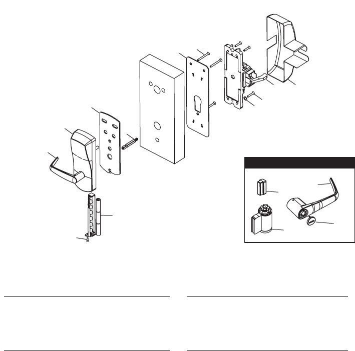
DIAGRAM OF LOCK:
BackFront
(A)
(D)
(B)
(E)
(F)
(G)
(H)
(I)
(J)
(C)
TOOLS REQUIRED:
TOOLS REQUIRED:
• Safety glasses
• 1⁄2" (13 mm) chisel
• 1⁄8" (3 mm) drill bit
• 1⁄2" (13 mm) drill bit
• 7⁄8" (22 mm) drill bit or hole saw
• 1" (25 mm) drill bit or hole saw
• 21⁄8" (54 mm) hole saw
• Drill
• Awl or center punch
• Rubber mallet
• Small flat screwdriver (less than 1⁄8")
• Phillips screwdriver (#2)
• Fine steel file
• Router
• Adjustable square
• Tape measure
• Pencil
• Tape
• Cleaning supplies (drop cloth,
vacuum)
• Spanner screwdriver #6
(A) Lock housing
(B) Inside drive hub
(C) Nylon washer
(D) Drive tube
(E) Lever catch
(F) Countersink
(G) Outside Lever
(H) Cap (if equipped)
(I) Cylinder (if equipped)
(J) Cylinder plug (if equipped)
6
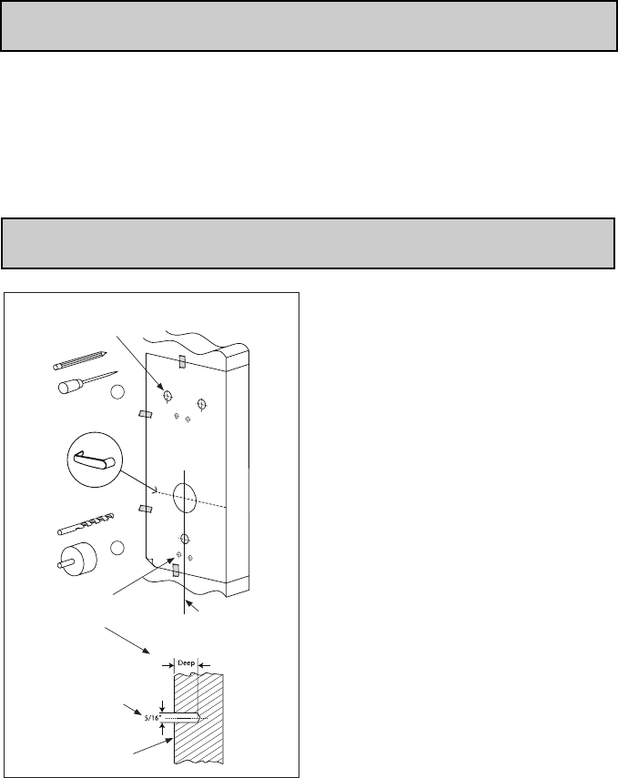
A-1. Door Preparation
Note: Drill from both sides of the door to prevent unsightly damage.
1. Determine which template fits your E-Plex 2xxx installation (either the
23⁄8" [60 mm] Backset or the 2 3⁄4" [70 mm] Backset).
2. Place appropriate paper template (supplied) onto door and mark for
holes. Drill the three 1⁄2" (13 mm) holes first. Next drill the 2 1⁄8" (54 mm)
cross bore hole. Drill the 1" (25 mm) hole last.
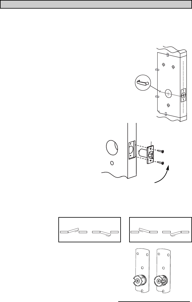
3. Mortise door edge for latch unit faceplate 3⁄16" (5 mm)
deep to dimensions shown. Insert latch unit into the
1" (25 mm) hole, making certain that the latch bolt
bevel faces direction of closing door.
4. Secure the latch to the door using two 1" (25 mm)
Phillips Mounting screws supplied. Latch unit
faceplate must be flush with door (for doors with
1" diameter hole, use sleeve on latch).
A-2. LOCK HANDING
The E-Plex 2xxx is a non-handed lock
that is preassembled for left-hand
door installations.
1. Determine the hand of your door. For Left Hand doors, proceed to section C.
For Right Hand doors, follow steps below.
2. Remove the two connecting screws from the
cylindrical drive unit. Rotate cylindrical drive
unit 180º. Reposition spacer(s) as found
before disassembly. Remount drive unit with
the two connecting screws.
D
Closing Direction
Left Hand Left Hand Reverse Bevel R
LEFT HAND DOOR
Right Hand Right Hand Reverse Bevel
RIGHT HAND DOOR
L
LH Assembly RH Assembly
Cylindrical Drive Unit Position
7
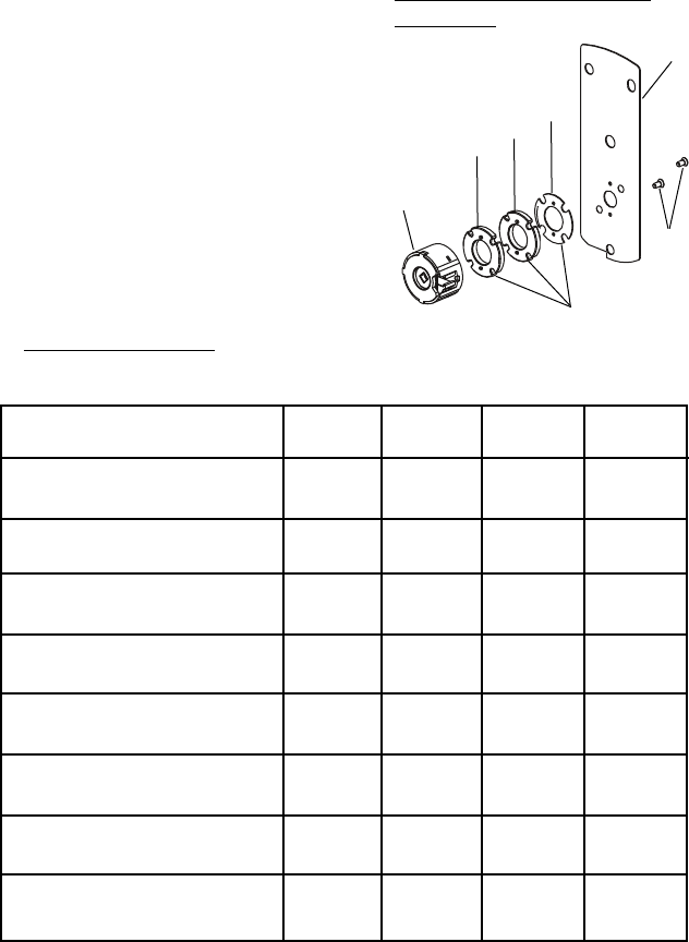
A-3. DOOR THICKNESS
Depending on the kind of spacers shipped with the lock, choose Table 1 or
Table 2 to prepare the attachment plate and cylindrical drive unit for door
thickness different than 1 3⁄4" assembled in the factory.
Note: It is very important to assemble the spacers in the position shown.
1. LOCK WITH 3 DIFFERENT SPACERS
The cylindrical unit and plate assembly is
shipped assembled in factory for 1 3⁄4"
(44 mm) door thickness (1 11⁄16" [43 mm]
to less than 1 7⁄8" [48 mm]) with 2 spac-
ers "04"; 1 spacer "02" and 2 flat head
screws 5⁄8" (16 mm) LG. For other door
thicknesses, use Door Thickness Table 1
for appropriate spacers and screws
included in the hardware bag.
Prepare attachment plate and
cylindrical drive unit for door
thicknesses less than 1 11⁄16"
(43 mm) or 1 7⁄8" (48 mm) and
above according to the
Door Thickness Table 1.
Door Thickness Table 1
Door Spacer Spacer Spacer Screw
Thickness 02 04 05 length
13⁄8" (35 mm) to -1 -
3⁄8"
19⁄16" (40 mm) (10 mm)
Over 1 9⁄16" (40 mm) to -2 -1⁄2"
less than 1 11⁄16" (43 mm) (13 mm)
13⁄4" (44 mm) DOOR 12 -
5⁄8"
111⁄16 (43 mm) to less than 1 7⁄8" (16 mm)
17⁄8" (48 mm) to 1- 1
5⁄8"
115⁄16" (49 mm) (16 mm)
Over 1 15⁄16" (49 mm) to 2- 1
3⁄4"
less than 2 1⁄8" (54 mm) (19 mm)
21⁄8" (54 mm) to - 1 1 3⁄4"
23⁄16" (56 mm) (19 mm)
Over 2 3⁄16" (56 mm) to 21 1
7⁄8"
23⁄8" (60 mm) (22 mm)
Over 2 3⁄8" (60 mm) to -- 2
7⁄8"
21⁄2" (64 mm) (22 mm)
Screws
Cylindrical
Unit
Assembly
05
04
02
Spacers
Attachment
Plate
Correct Position of Spacers
See Table 1
8
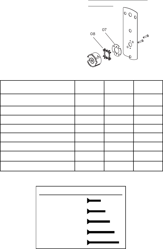
2. LOCK WITH 2 DIFFERENT SPACERS
The cylindrical unit and plate assembly is
shipped assembled in factory for 1 3⁄4"
(44 mm) door thickness up to 1 13⁄16" [46
mm] with 2 spacers "07"; 1 spacer "08"
and 2 flat head screws 5⁄8" (16 mm) long.
For other door thicknesses, use Door
Thickness Table 2 for appropriate spac-
ers and screws included in the hardware
bag.
Door Thickness Table 2
Door Spacer Spacer Screw
Thickness 07 08 length
13⁄8" (35 mm) to 1 9⁄16" (40 mm) 2-
3⁄8" (10 mm)
15⁄8" (41 mm) to 1 11⁄16" (43 mm) 11
1⁄2" (13 mm)
13⁄4" (44 mm) to 1 13⁄16" (46 mm) 21
5⁄8" (16 mm)
17⁄8" (48 mm) to 1 15⁄16" (49 mm) -2
5⁄8" (16 mm)
2" (51 mm) to 2 1⁄16" (52.5 mm) 12
3⁄4" (19 mm)
21⁄8" (54 mm) to 2 3⁄16" (56 mm) 2 2 3⁄4" (19 mm)
21⁄4" (57 mm) to 2 5⁄16" (59 mm) -3
7⁄8" (22 mm)
23⁄8" (60 mm) to 2 1⁄2" (64 mm) 13
7⁄8" (22 mm)
Screw Length Full Scale
Length 3⁄8"(10 mm)
Length 1⁄2"(13 mm)
Length 5⁄8"(16 mm)
Length 3⁄4"(19 mm)
Length 7⁄8"(22 mm)
Correct Position of Spacers
See Table 2
9
A-4. INSTALLING LOCK HOUSINGS
1. Remove the cylindrical plate assembly from
the outside housing (a). Insert the slotted end
of the square spindle into the outside housing
lever hub until it locks, at an angle of 45º.
(The spindle can be removed by pulling on it,
if oriented incorrectly.)
2. Assemble gasket onto the outside
housing (a). Assemble cylindrical plate
assembly onto the outside lock hous-
ing. (Not required for PowerPlex 2000
versions)
3. Place the outside housing (a) and
cylindrical plate assembly on the
door so that it engages the latch as
shown.
4.
On the inside trim assembly, turn the
lever to the correct horizontal rest
position for the handing of the door.
Install the tension spring (l) between
the stop plate (h) and the post (p).
Square Spindle Position
correct incorrect
a
Cylindrical Plate
Assembly
(outside)
cylindrical
unit
latch
h
p
l
Gasket (not for
PowerPlex 2000
version)
10
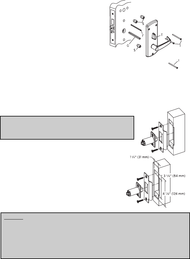
A-5. INSTALLING THE STRIKE
Note: Use only the strike and strike box supplied. The
use of non-approved parts will result in a functionality
problem and may void the warranty.
1. Mark location of strike on the door frame, making
certain that the strike opening is aligned with
latch bolt.
2. Mortise doorframe for strike 3⁄32" (3 mm)
deep minimum to dimensions shown. Make
cut out for dust box. Secure strike to the
door frame using two 1" (25 mm)
combination screws.
Caution: Check the operation of the latch by making sure that the deadlatch
stops against the strike as shown and does not slide into the strike opening
when the door is closed. If that situation occurs, then a total lockout may
occur. This will void our warranty of the complete lock mechanism. If
necessary, correct the door over-travel by using the rubber bumpers as
described in Section P (Installing Rubber Bumpers).
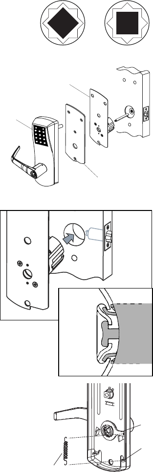
5. Put the thumbturn (T) in a vertical
position. Assemble 3 spacers (S) on
the door (for recent models only).
Place the inside trim assembly on the
door so that the upper and lower
spindles (F) and (G) engage the
thumbturn and the inside lever.
Fasten to the outside housing using
the three 1/8" hex drive mounting
screws (I). Install the screws without
tightening. Verify the inside lever and
thumbturn operates smootly. If not
move the inside and outside housings
slightly. Then tighten the screws.

11
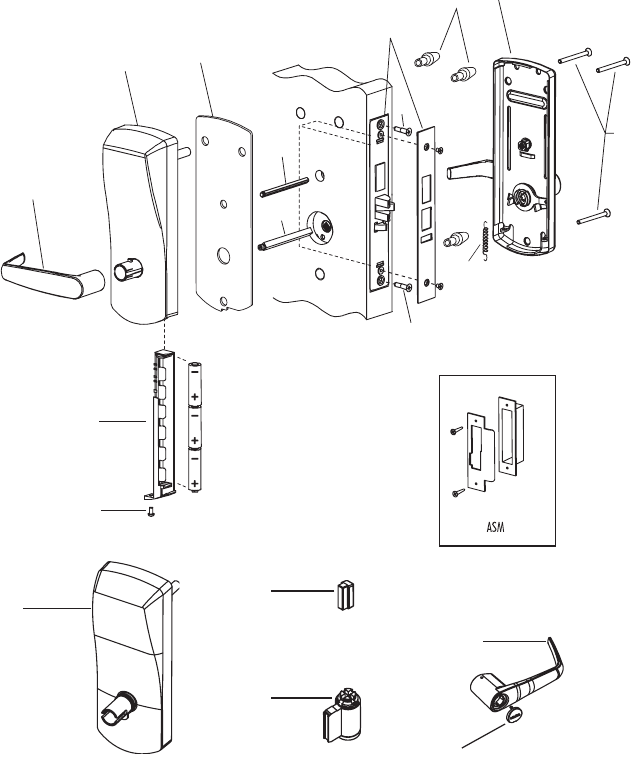
B. MORTISE
Checklist and Exploded Views (Mortise Only)
Each E2x00 Mortise lockset includes:
(A) Outside lever handle
(or)
Parts for Mechanical override model only:
(A1) Outside lever handle
(B1) Outside housing
(C1) Cylinder plug
(D1) Cylinder (for locks with KIL option)
(E1) Cylinder cap
(E2) Instruction sheet “How to attach lever on lock”
(B) Outside housing
(C) Battery holder with 3 AA batteries (not for PowerPlex 2000 versions)
(D) Mortise (ASM only shipped assembled with faceplate and 2 x 8-32 x 1/4”
screws)
(E) Inside trim assembly, details depend on lock model
(E3) Drilling template
(N) Outdoor Gasket (not for PowerPlex 2000 versions)
Parts inside hardware bag:
(F) Thumbturn (hex) spindle
(G) Square spindle
(H) Phillips screw (6-32X 5/16”) (not for PowerPlex 2000 versions)
(I) 3 x mounting screws (12-24, 1/8” Hex Head)
(J) 2 Machined screws (12-24X 1/2” Philips) & 2 wood screws (#12 X 1” Philips)
(K) Strike kit (screws, strike and dustbox)
(L) 1 extension spring
(R2) 1 Cylinder with 2 keys for E2x00 with override
(S) 3 spacers for recent Models only
(T) Allen Key 1/8”
(U) Allen Key 5/64”

12
Tools Required:
• Safety Glasses
• 1/2” (13mm) chisel
• 1/8” (3mm) drill bit
• 1/2” (13mm) drill bit
• 1” (25mm) drill bit or hole saw
• Drill
• Awl or center punch
• Hammer Rubber mallet
• Small flat screwdriver
• Philips screwdriver (#2)
• Fine steel file
• Mortising machine
• Router
• Mortise faceplate router template
• Adjustable square
• Tape measure
• Pencil
• Tape
• Cleaning supplies (drop cloth, vacuum)
13
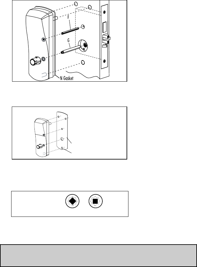
American Standard Mortise illustrated
A
C
H
B
N
F
D
S
G
J
J
L
I
E
K
B1
D1
C1
A1
E1
14
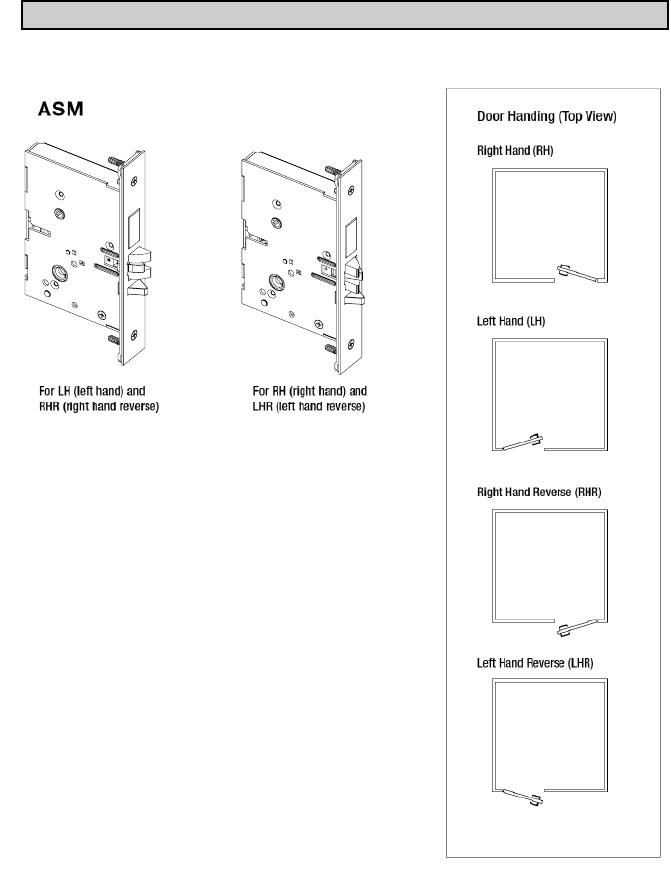
B-1. Installation of Standard ASM Models
1. Check the Mortise Handing
a. Compare the mortise with the diagram below. If the mortise is the
correct handing for the door, continue with step 2.
Note: Refer to B-2 to change the handing of a field-reversible mortise.
15
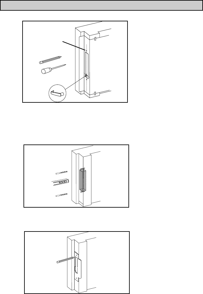
2. Install the Strike
a. Align the paper template on the door frame at the desired handle
height, and along the vertical center line of the mortise (CL), which is
also the center line of the door edge, allowing for any bumpers on the
door frame.
Note: Respect applicable building codes regarding handle height.
b. Mark the locations of the dust box cutout and mounting screws for the
strike.
c. Mortise the door frame to receive the dust box, and drill the pilot holes
for the mounting screws (dimensions and depths marked on template).
d. Position the strike against the doorframe and align it with the
mounting screw holes. Trace the outline of the strike.
(CL)
16
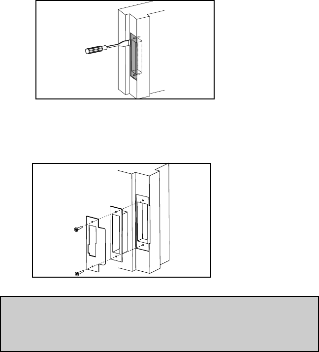
e. Remove material from within the strike outline so that the strike will
be flush with the doorframes.
f. For ASM, install the dust box (optional for wood door frames, required
for metal door frames), and check the strike handing on the template.
Install the strike using the screws provided. Use wood screws for wood
frame and machined screws for steel frames.
Note: When strike is installed on wood frames under one inch thick, wood
screws supplied are not adequate. Use screws of efficient length to
engage the structural stud behind the frame. Use only the strike and
dust box supplied. Use of non-approved parts may void the warranty.
17
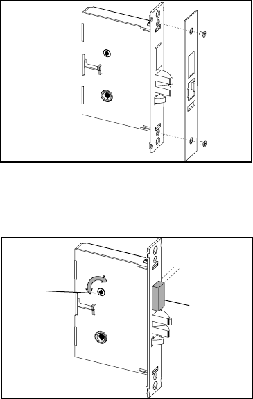
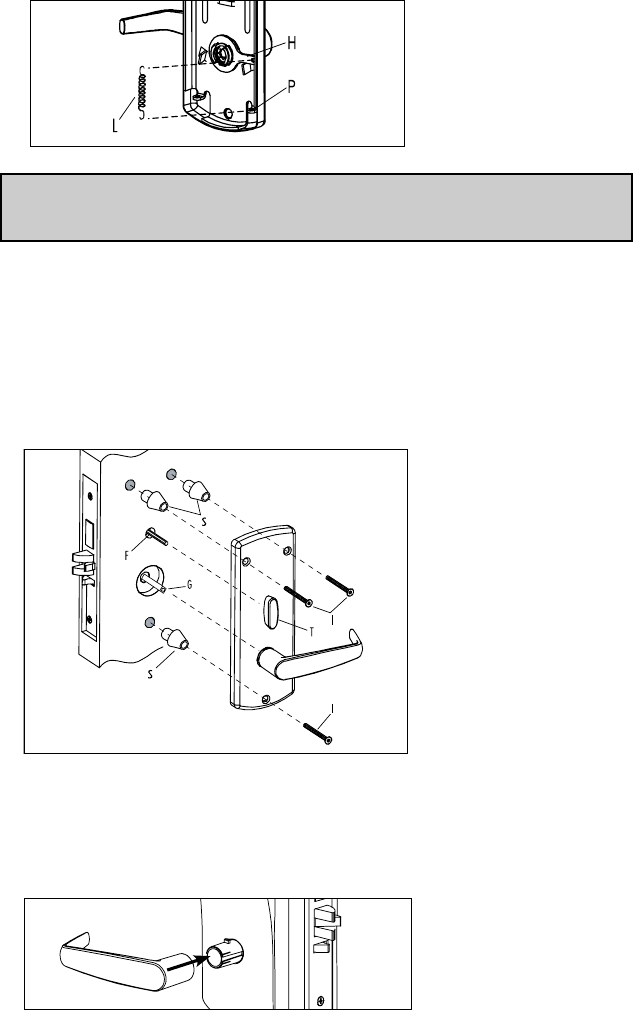
B-2. Reversing the Mortise Handing
1. Reversible ASM
a. Remove the mortise faceplate. Place the mortise on a flat surface
for the following steps.
b. Partially extend the deadbolt:
For normal ASM, rotate hub (H) using a screwdriver, until the deadbolt
(D) extends approximately 1/4”.
Proceed to step c.
1/4”
H
D
18
For Autodeadbolt ASM, rotate hub (H) until the deadbolt (D) is fully
retracted. The deadbolt will extend approx. 1/16” from the mortise case.
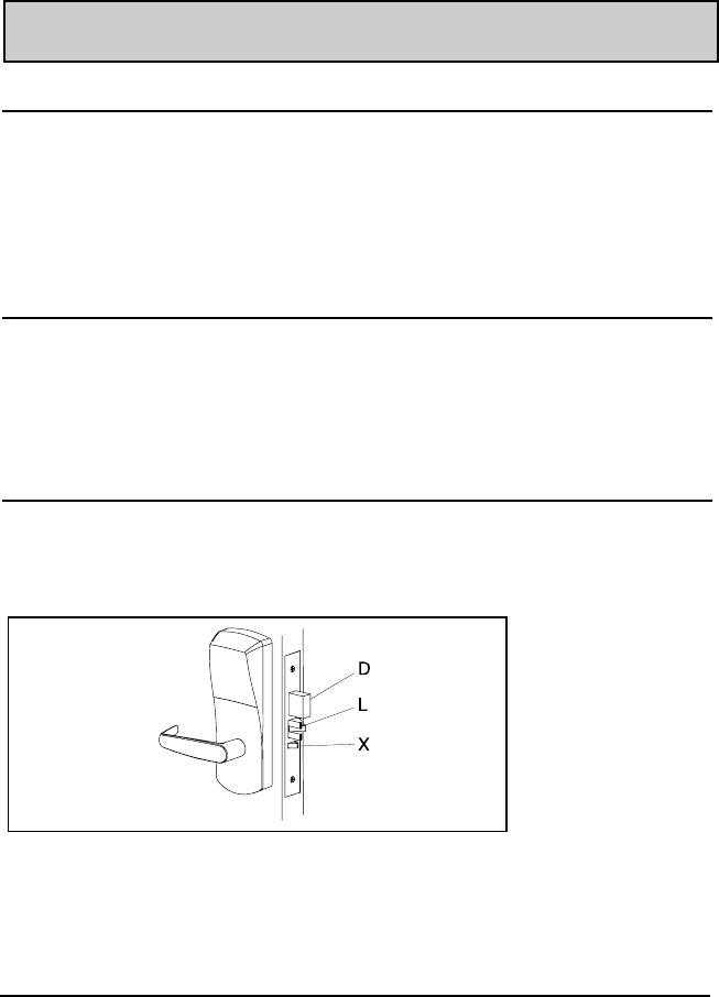
Hold deadbolt (D) gently. Press and release the auxiliary latch (X). You should
feel the deadbolt trigger and begin to extend under the force of the spring.
Release the deadbolt (D) gently. It should extend to 5/16” approx. and stop. If
the deadbolt extends past this point, gently press it in until it locks at 5/16”
throw, or start step b again.
D (hold gently)
X (press and release)
D
5/16”
D
1/16”
H
19
1. Reversible ASM (continued)
c. Push in the latch bolt (L) to the middle of its stroke, and hold it there.
(Continue Step 1 and 2)
Hold the latch (L) inside the mortise, and insert the tailpiece retaining
tool (S, part #027-510382 or #041-513342 available separately) so that
the tailpiece (T) will not drop inside the mortise case. Hold the tool and
the latch with one hand, and slide up the tailpiece using a small screwdriver.
Continue to hold tool (S). Release the latch bolt (L) and keep the anti-
friction latch (F) toward the flat side of the latch bolt so that the bolt
extends fully.
12
Use a small screwdriver
to lift unlock mechanism.
Unlock PositionLock Position
Push in the latchbolt to the
end of the stroke, and hold
it there.
LL
L
T
S
(part #027-510382)
L
F
S
20
d. Pull out the latch bolt (L), until it just clears the front plate. (Note: If
you remove the bolt completely, you must turn it 90° to re-insert it.)
Rotate the latch bolt (L) 180°. Re-insert it to the end of its stroke.
Holding tool (S) in place, re-engage tailpiece (T) with latch bolt (L)
(slide tailpiece down). There may be some play required to align the
parts. Remove the tool (S).
Release the latch to the middle of the stroke and hold it there. Use a
small screwdriver to push the lock mechanism back on lock position
(see step 1 and 2) .
Note: The lock mechanism has to be horizontal on lock position
L
180°
L
L
T
S
21
f. The mortise should look like the diagram below. (Check the orientation
of the latch bolt and auxiliary latch.) Check the bevel of the mortise and
change it if required as described in section B-4, paragraph 6.
m
For LH (left hand) and RHR
(right hand reverse)
For RH (right hand) and
LHR (left hand reverse)
ASM
W
V
W
V
Only apply to mortise no deadbolt,
auto-deadbolt and armed automatic deadbolt
e. Release the latch bolt (L). Position the latch bolt so that the bottom
tooth of the anti-friction latch (F) remains inside the mortise case as
shown.
Note: If the tooth of (F) is outside the mortise, you will not be able to re-
assemble the faceplate on the mortise.
L
F
L
F (tooth)
mortise
bottom view
6
m
a
22
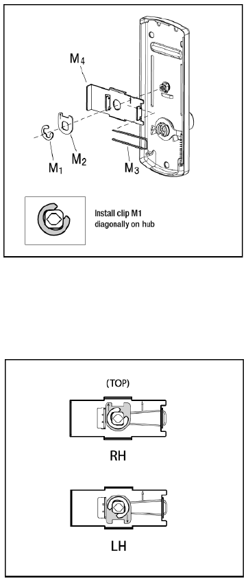
B-3. Additional steps for Autodeadbolt ASM inside trim assembly
If not already installed at the factory, put the thumbturn in the vertical position and
install all four (4) parts (M) as shown, on the inside trim assembly.
Turn the thumbturn all the way to the right for a RH installation (arrow on M2 points UP),
or all the way to the left for a LH installation (arrow on M2 points DOWN). The thumbturn
should stop in the vertical position, and the stopper cam (M2) will be in the position illus-
trated below.
23
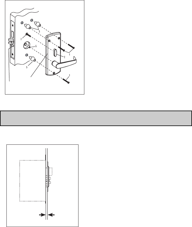
Place 3 spacers (S) on the door (for recent models only). Place the inside trim
assembly on the door so that the upper and lower spindles (F) and (G) engage the
thumbturn and the inside lever. Fasten to the outside housing using the three 1/8"
hex head mounting screws (I).
Note: For Auto Deadbolt models the gap between the mortise front plate and the
strike must not exceed 1/4 “
Turn Knob Vertical
X
Door Frame
M
Door Door Frame
Mortise
Max. 1
/4"

24
KABA E-PLEX®and PowerPlex 2xxx SERIES
LIMITED WARRANTY
Kaba Access Control warrants this product to be free from defects in material
and workmanship under normal use and service for a period of three (3) years.
Kaba Access Control will repair or replace, at our discretion, 2xxx Series Locks
found by Kaba Access Control analysis to be defective during this period. Our
only liability, whether in tort or in contract, under this warranty is to repair or
replace products that are returned to Kaba Access Control within the three (3)
year warranty period.
This warranty is in lieu of and not in addition to any other warranty or condi-
tion, express or implied, including without limitation merchantability, fitness for
purpose or absence of latent defects.
ATTENTION: This warranty does not cover problems arising out of improper
installation, neglect or misuse. All warranties implied or written will be null and
void if the lock is not installed properly and / or if any supplied component part
is substituted with a foreign part. If the lock is used with a wall bumper, the
warranty is null and void. If a doorstop is required, we recommend the use of a
floor secured stop.
The environment and conditions of use determine the life of finishes
on Kaba Access Control products. Finishes on Kaba Access Control products
are subject to change due to wear and environmental corrosion. Kaba Access
Control cannot be held responsible for the
deterioration of finishes.
Authorization to Return Goods
Returned merchandise will not be accepted without prior approval. Approvals
and Returned Goods Authorization Numbers (RGA Numbers) for the 2xxx
Series are available through our Customer Service department in Winston-
Salem, NC (800) 849-8324. The serial number of a lock is required to obtain
this RGA Number. The issuance of an RGA does not imply that a credit or
replacement will be issued.
The RGA number must be included on the address label when material
is returned to the factory. All component parts including latches and strikes
(even if not inoperative) must be included in the package with return. All
merchandise must be returned prepaid and properly packaged to the address
indicated.

KABA ACCESS & DATA SYSTEMS AMERICAS
2941 INDIANA AVE
WINSTON-SALEM, NC 27199-3770
NO POSTAGE
NECESSARY
IF MAILED
IN THE
UNITED STATES
BUSINESS REPLY MAIL
FIRST-CLASS MAIL WINSTON SALEM NCPERMIT NO. 1563
POSTAGE WILL BE PAID BY ADDRESSEE

Thank you for purchasing our product. In order to
protect your investment and to enable us to better
serve you in the future, please fill out this registration
card and return it to Kaba Access Control, or
register online at www.kabaaccess.com.
This lock will be used in what type of facility?
oCommercial Building oIndustrial / Manufacturing oAirport
oCollege/University oGovernment/Military oSchool/Educational
oHospital/Healthcare oOther (please specify)
What area is being secured with this lock? (e.g. Front Door, Common Door, Exercise Room)
This lock is:
oNew Installation
oReplacing a conventional keyed lock
oReplacing a Kaba Mechanical Pushbutton Lock
oReplacing a Kaba Electronic Access Control
oReplacing a Keyless Lock other than Kaba
How did you learn about Kaba Access Control Pushbutton Locks?
oAdvertisement o Previous Use oInternet / Web oAnother Use
oLocksmith oMaintenance oTraining Class oOther (please specify)
What was your reason for buying this lock?
Who installed your lock?
oLocksmith oMaintenance oOther
oCheck here if you would like more information on Kaba Access Control locks.
Name
Position
Company
Address
City
State ZIP (Postal Code) Country
Phone
Email
Name of Dealer Purchased From
Date of Purchase
Lock Model Number
REGISTRATION CARD
25
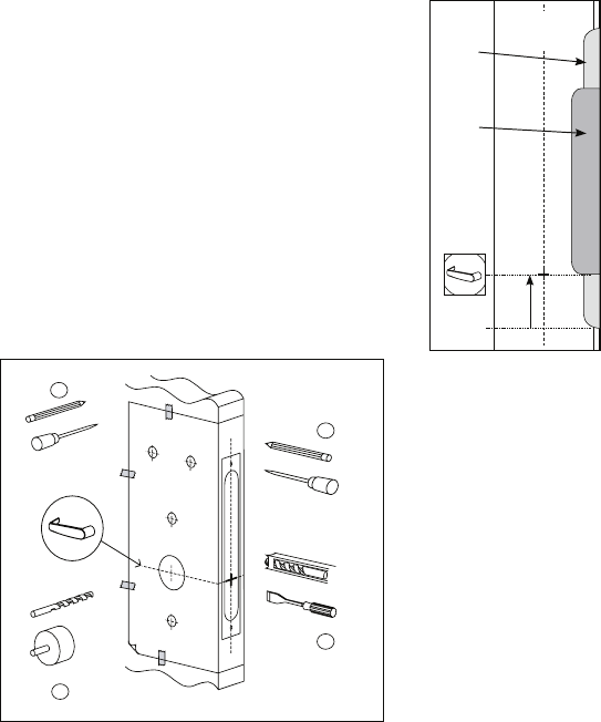
B-4. Install the Mortise
1. Mark the handle height on the edge of the
door, as determined directly from the strike.
For ASM, the axis of rotation of the handle is
level with the bottom lip of the strike.
2. Align the template along the vertical center
line of the mortise (CL) at the desired handle
height, and tape it to the door. Mark all holes
and cutouts for the mortise in the edge of the
door and remove the template.
ESM
Strike
(ESM)
ASM
Strike
11
/4"
Door
(CL)
(ASM shown) LH/RHR
3. Locate the two sets of vertical fold lines on the template allowing you to
adjust the positioning of the template depending on the bevel of the door.
If the door has no bevel, fold the template along the solid lines. Align the
fold with the edge of the door and mark the holes for the lock. Repeat on
the other side of the door.
If the door has a 3º bevel, fold and align the dashed line marked “H" on the
template with the higher-beveled edge of the door and mark the lock holes
on that side of the door. Repeat on the side with the lower-beveled edge
using the dashed line marked “L". Remove the template.
2
5
4
3
(ASM shown) LH/RHR
26
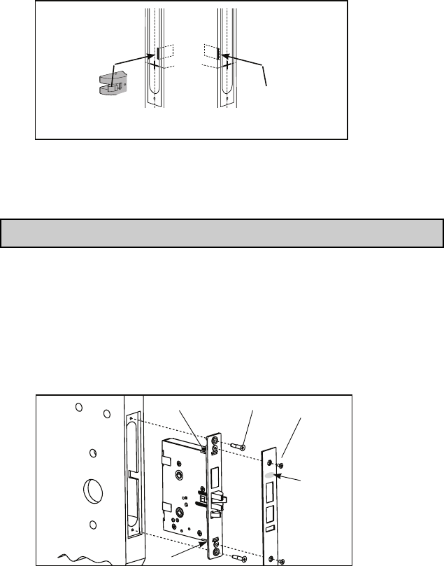
4. Prepare the cut-outs for the mortise in the edge of the door using a
mortising machine, router and chisel (for dimensions, refer to template).
Ensure clearance is provided for moving latch parts as indicated on the
template.
5. Drill the holes in the sides of the door (for dimensions, refer to template).
Note: Drill from both sides of the door to prevent unsightly damage
6. For ASM only, check the bevel of the mortise. If adjustment is required,
loosen bevel screws (R) and adjust mortise front plate angle to match the
bevel of the door. Re-tighten screws.
Install the mortise with 2 screws (Q). Use wood screws for wood doors
and machined screws for steel doors.
Install mortise faceplate (P) with the two 8-32 x 1/4" screws provided.
RH/LHR (ASM shown) LH/RHR
(ASM shown) LH/RHR
Logo
P
Q
R
R
27
B-5. Install the Outside Housing and Inside Trim Assembly
for 2000 and 2400 Series without Key Override (for
E2000 and 2400 Series Key Override, see Section F)
1. Install the gasket (N) (if required) on the outside housing prior to
assembly, aligning the notch in the gasket with the battery compartment.
2. Insert the slotted end of the square spindle (G) into the outside lever hub
until it locks, at an angle of 45º. (The spindle can be removed by pulling
on it, if oriented incorrectly.)
3. Insert the thumbturn spindle (F) in the upper hub of the outside housing.
(It will clip in place.)
Note: For doors more than 2 1/2” thick, order the appropriate hardware bag
to receive the correct length of spindles and mounting screws.
4. Place the outside housing on the door so that the spindles engage the
hubs on the mortise.
I
incorrect
I
Outdoor Gasket
Notch
incorrect
I
Square Spindle Position
correct incorrect
28
5. On the inside trim assembly turn the lever to the correct horizontal rest
position for the handing of the door. Install the tension spring (L)
between the handle (H) and the post (P).
Note: For Autodeadbolt ASM, Office and Storeroom models, refer to
section B-3
6. Put the thumbturn (T) in a vertical position. Place 3 spacers (S) on the
door (for recent models only) and place the inside trim assembly on the
door so that the upper and lower spindles (F) and (G) engage the thumb-
turn and the inside lever. Fasten to the outside housing using the three
1/8" hex drive mounting screws (I). Install the screws without tightening.
Verify the inside lever and thumbturn operates smootly. If not move the
inside and outside housings slightly. Then tighten the screws.
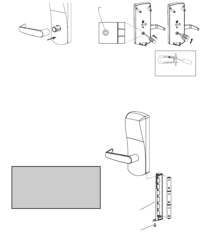
7. Assemble the lever on the outside housing, in the horizontal rest position
appropriate to the handing of the door. Simply push the lever onto the
tube until it clicks in place. If more force is required, use a rubber mallet.
Test the attachment of the handle by pulling smartly on it. (For locks with
key override, see p. 35)
incorrect
I
t
n
e
incorrect
29
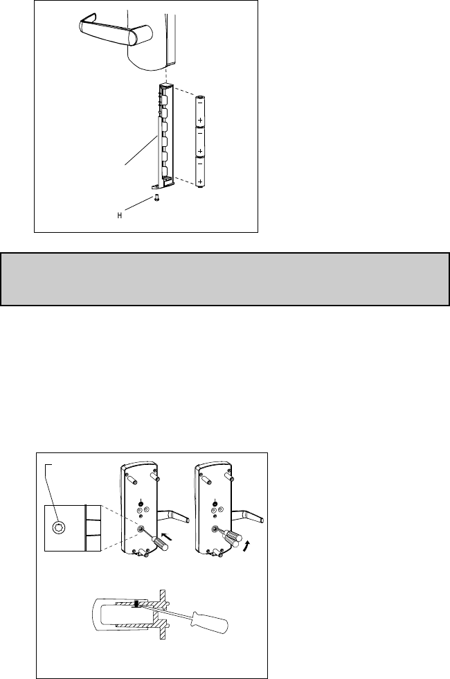
8. Three AA batteries should already be installed in the battery holder (C).
Insert the battery holder into the outside housing and secure it using the
supplied 6-32 x 5/16" (7.9mm) Phillips screw (H).
Note: If the lock makes a continuous buzzing noise or the red LED lights
continuously, reset the electronics by removing the battery holder for ten
seconds then reinsert it.
B-6. Reversing the Outside Lever
(for Series without Mechanical Override)
The lever is field reversible. If the handing is incorrect, insert a small pick or
flat screwdriver in the hole in the hub as shown. Gently pry back the spring
clip inside the hub, and remove the handle.
R
C
R
Access Hole
cut-away view
30
B-9.Testing (E-2400 Series ONLY)
Caution! Perform the following procedures in order, with the door OPEN
unless otherwise indicated.
Inside Lever:
Turn the inside lever downward. The latch bolt retracts fully.
If the lever or the thumbturn feels tight (hard to turn or does not return easily
to its horizontal position), check the alignment of the lock assemblies. Loosen
the mounting screws and shift the inside trim assembly slightly until the fric-
tion is eliminated. If the problem persists check the position of the holes on
the door (compared to the mortise).
Standard Deadbolt:
Turn the thumbturn back and forth. The deadbolt extends and retracts fully
and without undue friction.
Turn the thumbturn to extend the deadbolt again then turn the inside lever.
The deadbolt and the latch bolt retract simultaneously and fully without undue
friction.
Optional Autodeadbolt:
Press and hold the auxiliary bolt (X). The deadbolt (D) will extend. Keep the
auxiliary bolt depressed, and turn the inside lever all the way down and hold it
there. The latch (L) and deadbolt retract together.
Release the auxiliary bolt (X), then let the inside lever return to a horizontal
position. The deadbolt will remain retracted while the latch will extend.
Outside Lever:
Turn the outside lever downward. The latch bolt does not retract. If the latch
bolt retracts verify that the batteries are properly installed. If the lever feels
tight (hard to turn or does not return easily to its horizontal position), ensure
the square spindle is not too long or in proper orientation.
T
i

31
Programming
Program the Lock with at least one user with the Privacy/Deadbolt Override
privilege, and one user without this privilege, using the Oracode Maintenance
Unit.
Generate valid codes for these 2 users. (Recommendation: generate codes
that starts a day before today and finishes at least one day after current date,
in order to avoid check-in/check-out time periods)
Code entry and access
With the Deadbolt/Privacy deactivated, enter the first code to validate com-
plete lock operation.Verify that the green LED flashes at each key pressed and
a longer green LED flash at the end of the code entry. Turn the outside lever.
Make sure the latch bolt retracts fully. Release the lever, wait for the lock to
return to the locked mode (default settings is 5 seconds after unlocking), and
then turn the lever again.
The latch bolt must not retract after the lock has returned to locked mode,
which is typically 5 seconds (max 15 sec) after unlocking, without first entering
a valid user code.
Repeat with the second code.
Emergency Access (Deadbolt Override)
After programming turn the thumb turn to the horizontal position to engage
the Deadbolt/Privacy feature.
Deadbolt/Privacy engaged, access denied:
Enter the user code that does not have the Deadbolt/Privacy Override privi-
lege. Instead of the normal sequence of indicator LED with the green LED
flashing once indicating a valid code, this will be followed by a single red LED
flash, indicating access denied. Turn the outside lever, latch should not
retract. Access denied. If you see only the green LED flash once and /or the
latch retracting there might be a problem with the deadbolt/Privacy switch, or
you may have used a code with a Deadbolt/Privacy override privilege. Verify
thumbturn position. It should be vertical.
Emergency access: Deadbolt/Privacy engaged, user code with override privi-
lege, access granted: Enter the user code that has the Deadbolt/Privacy
Override privilege. You should see the normal sequence of indicator LED:
green LED flashes once. Turn the outside lever ,the latch and deadbolt
retracts simultaneously and fully: Access granted. If you see the red LED and
no Latch bolt retraction, verify that the code used has the deadbolt/privacy
override privilege enabled. Turn the thumb turn back to the vertical position if
not already so.

32
Operating the Override
Operating the Key Override, See Section H.
Note: If the lock will not respond to any code, there are three options that
should be attempted to open the door. In order, they are:
1. Verify the batteries, and replace them if they are providing less than 4
Volts total.
2. Use the electronic override feature (requires maintenance unit and
communication cable). Refer to maintenance unit user guide.3. Contact
Technical Support for instructions on using the drill point.
Deadbolt Deactivation:
A. Deadbolt Deactivation by Thumbturn
While standing inside the room, close the door and then turn the thumbturn to
extend the deadbolt. (If the lock has an autodeadbolt mortise, go to step B
below).
Turn the thumbturn to retract the deadbolt. Repeat.
B. Deadbolt Deactivation by Lever
While standing inside the room, close the door and turn the thumbturn to
the horizontal position to extend the deadbolt (or to select privacy on
autodeadbolt models). Open the door by turning the lever. The deadbolt
and the latch bolt retract simultaneously and fully. Take note of any
excess friction, which might necessitate filing the strike (deadbolt area
only). Repeat.
33
C. EXIT TRIM
C-1. CHECKLIST FOR PRECISION EXIT DEVICES 21/22/
FL21/FL22 VON DUPRIN 98/99EO-F/9827/9927
EO- F/9875/9975/9847/9947
** DETEX 10/F10/20/F20
DORMA F9300
YALE 7100/7160/7170
Mechanical Override Models ONLY
A
K
B
C
D
Q
H
GG
E F
L
J
P
M
N
(Not for PowerPlex
2000 Versions)
(Not for PowerPlex 2000
Versions)
** Detex 10 & 20 Series are Panic Hardware only. (Not fire rated)
Detex F10 & F20 Series are Fire Exit Hardware (Fire Rated)
Each ockset includes:
(A) Outside lever handle
(B) Outside housing
(C) Gasket (when required)
(J) Battery holder with 3 AA batteries
Parts inside hardware bag:
(D) 1 or more spindles as equipped
(E) 1 x Inside Adaptor Plate
(F) 3 x Mounting Screw 12-24 1/8” Hex
(H) 2 x Pan Head Screws 1/4” 28 X 3/4” for Yale
2 or 4 Pan Head Screws 10-24 X 3/4” for Detex, Dorma,
Von Duprin or 4 Flat Head screw 10-24 X 5/8” for Precision,
Arrow
(K) 1 x Pan Head Screw
(Q) 2 or 4 Flat Washer 1/2OD for Detex Exit Device Only
Mechanical Override Models ONLY:
(L) Cylinder Cap
(M) Cylinder Plug
(N) Outside Lever Handle
(P) Cylinder (for 630 series lock with cylinders keyed
different ONLY)
Tools Required:
Safety glasses Spanner screwdriver (No 6)
5/16” (7.9mm) drill bit 1/8” Allen key
1/2” (13mm) drill bit Adjustable square
1” (25mm) drill bit or hole saw Tape measure
Drill Pencil
Awl or center punch Tape
Hammer Cleaning supplies
Rubber mallet (drop cloth, vacuum)
Small flat screwdriver
Philips #2 screwdriver
34
C-2. PREPARE THE DOOR FOR THE APPROPRIATE EXIT DEVICE
1. Choose the drilling template of the lock for the exit device to be assembled on
the door.
2. Mark the desired handle height on the edge of the door. (see Fig.1)
3. Mark the backset vertical line on each side of the door. Consult the exit device
manufacturer’s instructions for the correct backset. The backset shown on the
paper template is for reference only. use exit device backset.
Note: Respect all applicable building codes regarding the handle height of the
lock and positioning of the bar.
4. Position the drilling template on the inside of the door aligning the door handle
height mark and backset vertical line mark with the lines on the template. Mark
the door for the holes position.
5. Drill holes to diameters specified on the drilling templates.
Drill the holes in the door required for the exit device according to the
manufacturer’s instructions.
Note: Drill from both sides of the door to prevent unsightly damage. Refer to
template for drill size and depths.
3 through holes
From the inside, counter bore
5/16 dia. X 3/4 Deep
See Drilling Template
2 or 4 Holes
Backset Vertical Line
Inside of Door
4
3
4
Fig. 1
Fig. 2
7/8”
7/8
35
6
p
I
J
K
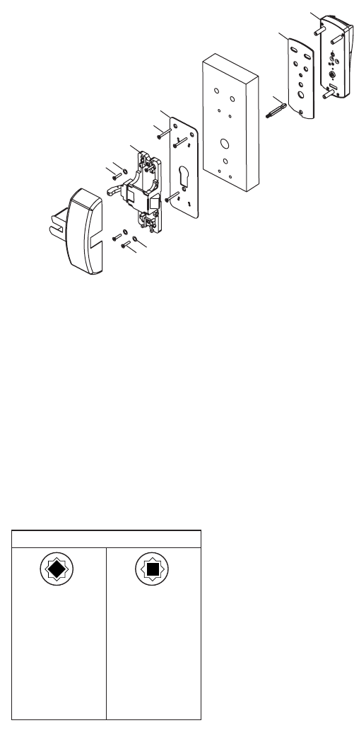
C-3. INSTALL THE LOCK AND EXIT DEVICE
1. Install the Mortise (if applicable)
For mortise exit devices, install the mortise according to the
manufacturer’s instructions
2. Install the Outside Lever
6
Assemble the lever on the outside housing, in the horizontal rest
position appropriate to the handing of the door as shown. Simply push
the lever onto the tube until it clicks in place. If more force is
required to engage the handle, use a rubber mallet. Test the attach-
ment of the handle by pulling smartly on it.
F
The lever is field reversible. If the handing is
incorrect, insert a small pick or flat screwdriver
in the hole in the hub as shown. Gently pry
back the spring clip inside the hub, and remove
the handle.
AB
I
Access Hole
cutaway view
A. Assemble the lever on the outside housing,
in the horizontal rest position appropriate to
the handing of the door as shown. Simply
push the lever onto the tube until it clicks in
place. If more force is required to engage the
handle, use a rubber mallet. Test the attach-
ment of the handle by pulling smartly on it.
B. The lever is field reversible. If
the handing is incorrect, insert a
small pick or flat screwdriver in
the hole in the hub as shown.
Gently pry back the spring clip
inside the hub, and remove the
handle.
3. Install the Batteries
(Not for PowerPlex 2000 versions)
Three AA batteries should already
be installed in the battery holder
(J). Insert the battery holder into
the outside housing and secure it
using the 6-32 X 3/8” spanner drive
screw (K).
Note: If the lock makes a continu-
ous buzzing noise or the red LED
lights continuously, reset the
electronics by removing the bat-
tery holder for ten seconds, then
reinsert it.
36
4. Install Lock & Exit Device on the door
b. Insert the slotted end of the spindle (D) into the outside housing until
it locks, at the correct position for the exit device (see Fig.4). The
spindle can be removed by pulling on it, and re-inserted if oriented
incorrectly.
c. Place the outside housing (B) on the door. (with gasket (C) if required)
d. Attach Adaptor Plate (E) to the lock (B) using Flat Head screws
(F)(12-24nc).
e. Attach the Exit Device chassis (G) to the Adaptor Plate (E) using 2
screws or 4 screws (H) depending on the Exit Device. For Detex only,
use 2 or 4 Flat washers (Q).
f. Make sure the lock and the Exit Device are well aligned and then
tighten screws.
g. Follow the manufacturer’s instructions to complete the installation of
the exit device and the appropriate strike.
H
Q
D
C
B
G
Q
H
E
F
a. Choose the required
SPINDLE BAG from the
spindle chart in the
Hardware bag depending
ON THE TYPE OF EXIT
DEVICE AND THE
DOOR THICKNESS
In
Attach Adaptor Plate (E) to the lock (B) using 3 Flat Head screw (F)(12-
2
Attach the Exit Device chassis (G) to the Adaptor Plate (E) using 2 screws or
4
Make sure the lock and the Exit Device are well aligned and then tighten
s
Follow the manufacturer’s instructions to complete the installation of the exit
d
Spindle Position
Von Duprin 98/99
Von Duprin 9847/9947
Von Duprin 9827/9927
Precision 21/FL21
Precision 22/FL22
Arrow S3888
**Detex 10/F10
**Detex 20/F20
**Detex V40
Yale 7100-36
Yale 7160
Yale 7170
Dorma F9300
Von Duprin 9875/9975
Arrow S1908/S3908
Arrow S1708/S3708
Arrow S1808/S3808
Fig. 4
In
Attach Adaptor Plate (E) to the lock (B) using 3 Flat Head screw (F)(12-
2
Attach the Exit Device chassis (G) to the Adaptor Plate (E) using 2 screws or
4
Make sure the lock and the Exit Device are well aligned and then tighten
s
Follow the manufacturer’s instructions to complete the installation of the exit
d
**Detex 10/F10
**Detex 20/F20
*
In
Attach Adaptor Plate (E) to the lock (B) using 3 Flat Head screw (F)(12-
2
Attach the Exit Device chassis (G) to the Adaptor Plate (E) using 2 screws or
4
Make sure the lock and the Exit Device are well aligned and then tighten
s
Follow the manufacturer’s instructions to complete the installation of the exit
d
Yale 7100-36
Yale 7160
Yale 7170
Dorma F9300
V
** Detex 10/20 Series are Panic Hardware only. (Not fire rated)
Detex F10/F20 Series are Fire rated hardware

37
D. INSTALLING OUTSIDE LEVER ON
NON-MECHANICAL OVERRIDE
Assemble the lever on the outside housing in the hori-
zontal rest position appropriate to the handing of the
door. Simply push the lever onto the tube until it clicks
in place. If more force is required, use a rubber mallet. Test the attachment of
the handle by pulling on it to make sure it is securely fastened.
E. REVERSING THE OUTSIDE LEVER
FOR SERIES WITHOUT
MECHANICAL OVERRIDE
The lever is field reversible. If the handing
is incorrect, insert a small pick or flat
screwdriver in the hole in the hub as shown. Gently
pry back the spring clip inside the hub, and remove
the handle.
38
F. INSTALLING OPTIONAL K-I-L KEY OR BEST
REMOVABLE CORE OVERRIDE AND OUTSIDE LEVER
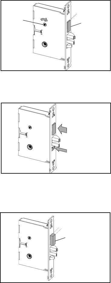
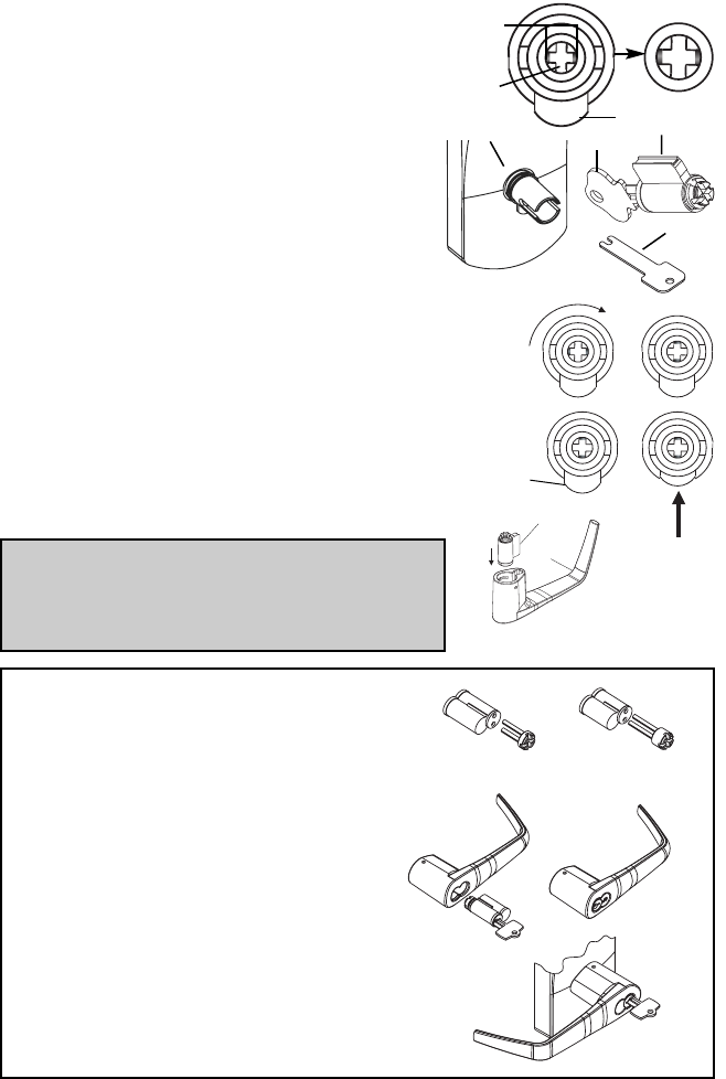
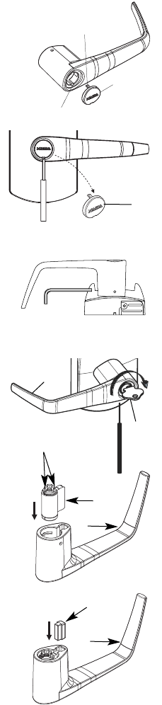
F-1 Upon unpacking, the lock housing with mechanical
override should look like the diagram below with:
• The small indents (i) on the cross of the
override shaft (m) in line horizontally
• The plastic washer (c) on the drive tube
• The lever catch (f) in the out position
• Cylinder (j) and 2 keys (n) (included in the
hardware bag)
• Shaft override tool (o) (included in the
hardware bag)
F-2 Using the override shaft tool (o), turn the override
shaft clockwise until it stops so that the two small
indents on the cross are now vertically in line.
F-3 Push in the lever catch (f) firmly.
F-4 Insert the cylinder (j) into the lever handle (h).
Note: For Best Removable Core, use Steps F-5,
F-6 and F-7, then proceed to F-10 and continue.
For Optional K-I-L Key, skip ahead to F-8 and
proceed as normal.
For Best Removable Core
F-5 Insert 6-pin Best adapter (thicker) into
6-pin interchangeable core or insert
7-pin Best adapter (thinner) into 7-
pin interchangeable core. Insert the
adapter until it makes contact with
the removable core.
F-6 Using the control key, assemble the
removable core with its adapter into
the lever. Remove control key.
F-7 Insert the change key into the removable
core.
f
7-pin
adapter
Thinner
adapter
Thicker
6-pin
(j
)
(o
)
h
j
(f)
(i)
(m)
(c, d) (n)
39
For Optional K-I-L Key
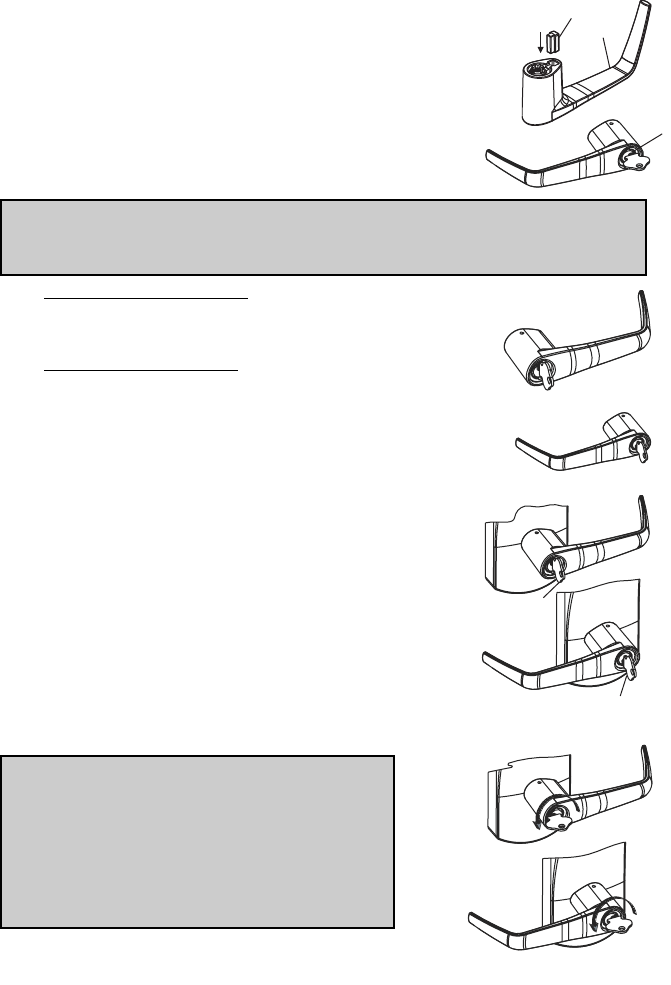
F-8 Put the cylinder plug (k) into the lever (h).
F-9 Making sure that the cylinder plug (k) does not fall
out, insert the key into the cylinder (j). The key will
be horizontal.
Caution: The position of the key is very important. If the lever is not assembled
with the key in the correct position before placing the lever on the housing, the
inside mechanism of the lock could be damaged if the lever is rotated and forced.
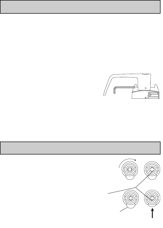
F-10 For Right-Handed Levers: Turn the key clockwise until
it stops so that it is in the vertical position and the
countersink (g) is in the top position.
For Left-Handed Levers: Turn the key clockwise until
it stops so that it is in the vertical position and the
countersink (g) is in the bottom position.
F-11 Fit the lever handle (h) onto the drive tube. It
should rest approximately 1⁄16" (2 mm) from the
body of the housing. If it can’t be pushed that close
to the housing, the lever catch (f) is probably not
pushed in. Push it in. If the lever catch (f) is stuck,
the override shaft is in the wrong position. The
two small indents on the cross of the override
shaft must be vertically aligned.
F-12 Press the lever firmly against the housing
while turning the key counter-clockwise
(this applies to both Right-Handed and
Left-Handed locks) until it is in the horizontal
position.
Important: If it is not possible to turn the key
counter-clockwise to complete this step, the
spring washer (d) may be too tense:
Tap the lever carefully with a rubber mallet to
loosen the spring washer (d). Cover the lever
handle with a cloth or other material to
protect the finish of the metal.
Right-Handed
lock
Countersink (g)
in TOP Position
Countersink (g) in BOTTOM Position
Left-Handed
lock
Right-Handed
lock
Left-Handed
lock
h
j
k
Countersink (g) in
the top position
Countersink (g) in
the bottom position
40
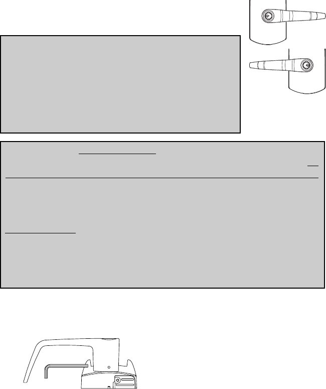
F-13 Remove the key. The lock will look as shown at right.
F-14 Gently check the rotation of the lever handle.
It should easily rotate approximately 45º.
Troubleshooting: If you have assembled the lever and
housing with the key in the wrong position, the key will get
stuck. To remove the key, turn it so that it is in the vertical
position and insert a small flat screwdriver into the hole
under the lever handle to push the lever catch in (f).
Remove key. If it is still stuck, turn the key clockwise until
it stops to the horizontal position and push the Lever
Catch in again with the small screwdriver. Remove key.
Troubleshooting: Right-Handed Lock: Turn the lever handle clockwise without
forcing it. If it stops at approximately 15º, it was not assembled correctly. Do
not try to force it to turn - this will damage the inside mechanism of the lock.
Release the lever handle. Insert the small screwdriver into the small hole on
the underside of the lever handle and push in the lever catch.
Re-do steps in section D
Left-Handed Lock: Turn the lever handle counter-clockwise without forcing. The
drive hub should not rotate when the lever handle is turned. If it does, it was not
assembled correctly. Release the lever handle. Insert the small screwdriver into
the small hole on the underside of the lever handle and push in the lever catch.
Re-do steps in section D
F-15 Using the 5/64” Allen Key, tighten the set screw while pushing the lever
against the plastic washer to remove the lever play.
G. TESTING THE OPERATION OF THE OUTSIDE LEVER
G-1 Verify that the lever has been correctly attached to the housing:
a. Remove key.
b. Insert a small flat screwdriver into the hole on the underside of the lever
handle and push in the lever catch.
c. Pull on the lever.
You should not be able to remove the lever. If the lever comes off of the
housing, the lock is not assembled correctly. Return to steps in section D
and repeat this verification process.
Right-Handed lock
Left-Handed
lock
41
G-2 Test the Movement of the Lever
(without the key in cylinder)
a. Turn the lever (h) clockwise for a Right-Handed lock
or counter-clockwise for a Left-Handed lock
b. Release the lever slowly. It should return freely to its
horizontal position.
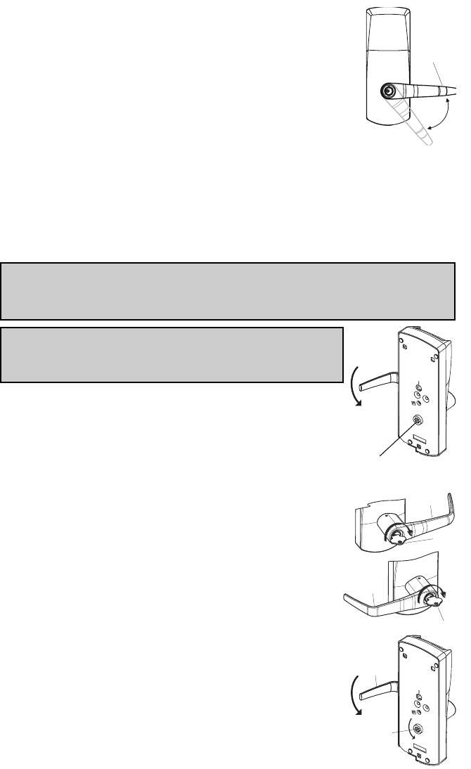
H. TESTING THE MECHANICAL KEY
OVERRIDE WITH CHANGE KEY
Important: The Key Override itself does not retract the latch or deadbolt. Do not
use too much force when turning the key as this may damage the unit. To retract
the latch, turn the key clockwise until it stops, release the key and turn the lever.
Note: The lever must stay in the horizontal position when
turning the key (do not try to turn the key while turning
the lever) or the override mechanism will not work.
H-1 Without using the key, turn the lever clockwise for
Right-Handed locks or counter-clockwise for Left-
Handed locks. The inside drive hub should not rotate
when the lever turns.
H-2 With the lever (h) in the horizontal position, insert
the key (n) into the cylinder and turn it clockwise
until it stops. (This applies to both Right and Left-
Handed locks.)
H-3 Let go of the key, and again turn the lever handle
(h) clockwise for Right-Handed locks or counter-
clockwise for Left-Handed locks. Now the inside
drive hub (b) should rotate in the same direction
as the lever handle when it is turned.
Inside drive hub
does not move
h
n
h
b
h
n
h
42
H-4 Install cap (i) to cover key hole. The cap has a small
groove on one edge (to allow ease of removal). This
should be facing down. Insert bottom snap of cap in
lever hole below the cylinder. With a small screw-
driver, push top snap of cap down while pushing the
cap into place.
H-5 To remove the cap (i), insert a small flat screwdriver
into this groove and gently pry the cap off,
being careful not to damage it. Cover the
bottom of the lever to protect the finish
from being scratched through the process of
removing the cap.
I. CHANGING KEY-IN-LEVER LOCK CYLINDERS
I-1 Loosen the set screw to free the lever (just
1/4 to 1/2 turn).
I-2 Remove the cap from the outside lever (h).
I-3 Insert key (n).
I-4 Turn the key clockwise until it stops.
I-5 Release key (n).
I-6 Use a small flat screwdriver to push in
the lever catch through the small hole
underneath the outside lever
I-7 Pull the outside lever (h) off of the lock housing.
Be careful not to lose the cylinder plug (k).
If it is difficult to pull the lever, slightly tighten
or loosen the set screw
I-8 Replace the old cylinder with the new one in the
lever handle. Only the same kind of cylinder with
2 grooves in cross in the end of the cylinder plug
can be used on the lock.
I-9 Re-insert the cylinder plug (k).
I-10 While holding the cylinder (j) and plug (k) in place,
insert the key.
I-11 Follow steps F-10 to F-14 and Test as per steps
G and H.
2 Grooves
in cross
j
k
h
h
h
Hole below cylinder
Bottom snap
i (First)
Top snap
(Second)
n
i
43
J. CHANGING BEST-TYPE CORE
J-1 Use the control key to remove the removable core from the lever
J-2 Remove the adapter from the removable core and reassemble it on the
new removable core.
Note: It is important that the new removable core has the same number of
pins (6 or 7) as the dismounted one. If not, change the adapter to fit the core.
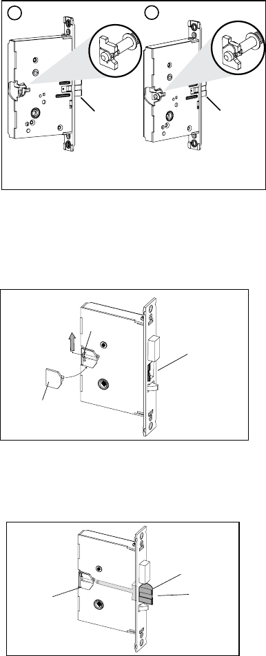
J-3 Check to make sure that the override shaft did not move and that the 2
small indents on override shaft are still vertical (see below). Then, using the
control key on the new core, assemble the new removable core on the lever.
J-4 Test the locks using Steps G and H.
K. REMOVING AND REASSEMBLING
THE OUTSIDE LEVER
K-1 Loosen the set screw to free the lever
(just 1/4 to 1/2 turn).
K-2 Insert the change key in the cylinder.
K-3 Turn the key clockwise until it stops (for
both right and left-hand locks).
K-4 Release the key.
K-5 Use a small flat screw driver to push in the lever catch through the small
hole underneath the outside lever.
K-6 Pull the outside lever off of the lock housing. Be careful not to lose the
adapter.
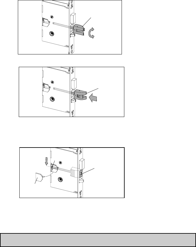
Important: Assemble the lever, cylinder and lock components before affixing
the entire unit to the door.
K-7 Ensure that the two small indents on the cross are
now vertically in line. (The cylinder or override shaft
tool can be used to turn override shaft.)
K-8 Push in the lever catch (f) firmly.
2 indents
vertical
f
44
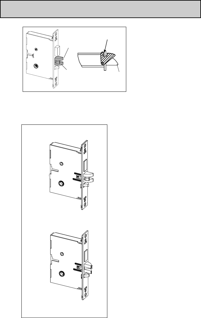
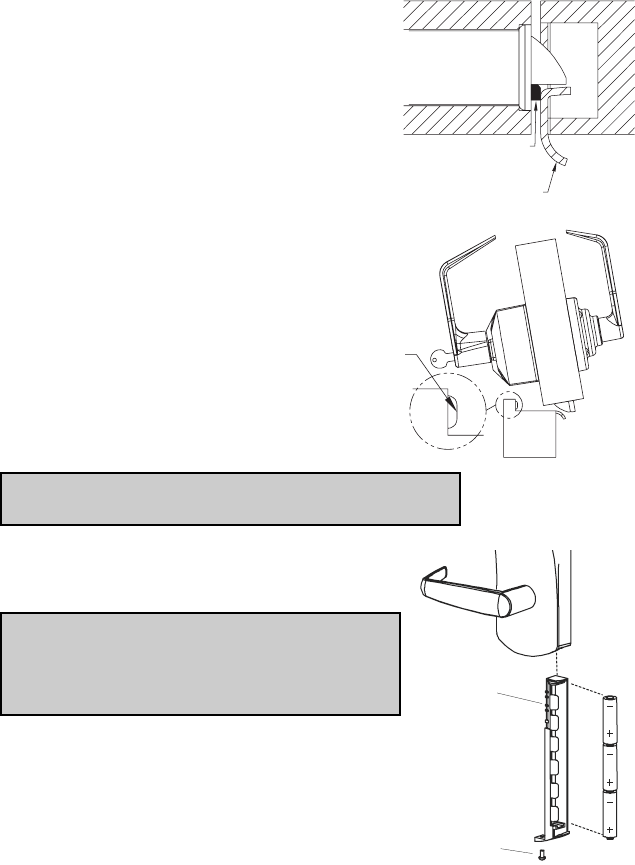
L. INSTALLING RUBBER BUMPERS
L-1 Close the door and apply pressure making
sure the deadlatch (a) rests on the strike
plate (b) as shown. Standing on the frame
(door stop) side of the door, check for gaps
between the door and the frame on the
three sides of the frame (left, right, and
top).
L-2 Mark locations where the gaps are
approximately 3⁄16" (5 mm). Make sure
these locations are free from grease and
dust. Peel the bumpers (c) from their
protective backing without touching the
adhesive surface and stick them on the
marked locations.
Note: Allow 24 hours for adhesive to set before testing.
The door may be operated normally during this time.
M. INSTALLING BATTERY PACK
(Not for PowerPlex 2000 Versions)
Note: If the lock makes a continuous buzzing
noise or the red LED lights continuously, reset
the electronics by removing the battery holder
for ten seconds, then reinsert it.
M-1 Three AA batteries should already be
installed in the battery holder (q).
M-2 Insert the battery holder into the outside
housing and secure it using the 6-32 x 5⁄16"
(8 mm) screw (r).
c
a
Correct
b
q
r
45
N. TESTING THE OPERATION OF THE LOCK
N-1 Rotate inside lever and hold. Ensure that the latch is fully retracted and
flush with the latch faceplate. Release the inside lever; the latch should be
fully extended.
N-2 For PowerPlex 2000 you need to activate the outside lever 3 to 4
times to power the lock prior
N-3 Enter the factory-set combination: 1,2,3,4,5,6,7,8. You should see a green
light and hear a high pitched tone as you push each button. When the lock
opens, you will briefly hear the sound of an electronic motor. Rotate out
side lever and hold. Ensure that the latch is fully retracted and flush with
the latch faceplate. Release the outside lever; the latch should be fully
extended. When the lock re-locks, you will again hear the mot or.
N-4 If your product is an E24xx, you will have to generate an access code using
the web application to test the lock operation.
N-5 With the door open, verify functionality of the mechanical Key Override as
detailed in Section F.

Kaba Access & Data Systems Americas
2941 Indiana Avenue
Winston-Salem, NC 27105 USA
Tel: 800.849.8324 336.725.1331
Fax: 800.346.9640 336.725.3269
www.kaba-adsamericas.com PKG3218 0413
