Kaba Access Installation Instructions E Plex Electronic Pushbutton Lock 5000/5200/5600/5700 Series Exit 5x00 Pkg3055
E-Plex 5x00 Series Installation Instructions Exit - PKG3055 e-plex-5x00-series-installation-instructions-exit-pkg3055 E-Plex 5700 Electronic Pushbutton Lock - Kaba Access & Data Systems
Kaba E-Plex Electronic Pushbutton Lock - 5000/5200/5600/5700 Series Exit Installation Instructions e-plex-5x00-series-installation-instructions-exit-pkg3055 Installation Instructions
User Manual: Kaba Access Kaba E-Plex Electronic Pushbutton Lock - 5000/5200/5600/5700 Series Exit Installation Instructions Installation Instructions
Open the PDF directly: View PDF ![]() .
.
Page Count: 20

E-PLEX®
5X10 EXIT TRIM MODELS
INSTALLATION INSTRUCTIONS

2
TABLE OF CONTENTS
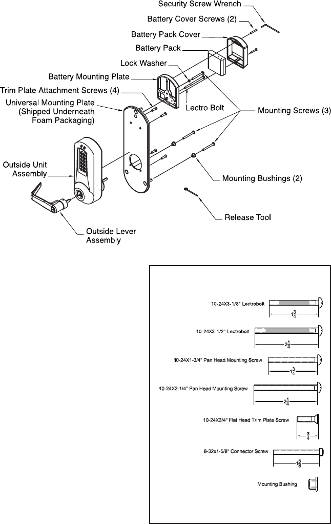
Assembly Drawing . . . . . . . . . . . . . . . . . . . . . . . . . . . . . . . . . . . . . . . . . . . . . . . . . . . . . . . . . . . . . .3
Tools Required . . . . . . . . . . . . . . . . . . . . . . . . . . . . . . . . . . . . . . . . . . . . . . . . . . . . . . . . . . . . . . . . .4
A. Door Preparation – Exit Device . . . . . . . . . . . . . . . . . . . . . . . . . . . . . . . . . . . . . . . . . . . . . . .5
B. Door Preparation – E5000 Exit Trim . . . . . . . . . . . . . . . . . . . . . . . . . . . . . . . . . . . . . . . . . .6
C. Install Exit Device . . . . . . . . . . . . . . . . . . . . . . . . . . . . . . . . . . . . . . . . . . . . . . . . . . . . . . . . . . .6
D. Door Thickness . . . . . . . . . . . . . . . . . . . . . . . . . . . . . . . . . . . . . . . . . . . . . . . . . . . . . . . . . . . . .7
E. Assemble Outside Unit to Universal Mounting Plate . . . . . . . . . . . . . . . . . . . . . . . . . . . . .7
F. Lock Handing . . . . . . . . . . . . . . . . . . . . . . . . . . . . . . . . . . . . . . . . . . . . . . . . . . . . . . . . . . . . . .7
G. Changing Key-In-Lever (KIL) Cylinder . . . . . . . . . . . . . . . . . . . . . . . . . . . . . . . . . . . . . . . . .8
H. Installing/Removing Outside Lever (Key-In-Lever Models) . . . . . . . . . . . . . . . . . . . . . . .9
I. Installing/Removing Outside Lever (Interchangeable/Removable Core Models) . . . . .9
J. Installing E5x00 Exit Trim . . . . . . . . . . . . . . . . . . . . . . . . . . . . . . . . . . . . . . . . . . . . . . . . . . .11
K. Installing The Battery Pack and Cover Changing Batteries . . . . . . . . . . . . . . . . . . . . . .12
L. Testing the Operation of the Lock . . . . . . . . . . . . . . . . . . . . . . . . . . . . . . . . . . . . . . . . . . . .13
M. Programming and Software Settings . . . . . . . . . . . . . . . . . . . . . . . . . . . . . . . . . . . . . . . . .14
Warning
The Master Code of this lock has been factory preset: 1,2,3,4,5,6,7,8.
To activate lock functions, the master combination must be changed
at time of installation.
Warnings and Cautions
Important: Carefully inspect windows, doorframe, door, lights, etc. to
ensure that the recommended procedures will not cause damage. Kaba
Access Control’s warranty does not cover damages caused by installation.
Caution: Wear safety glasses when preparing door.
3
E-PLEX 5x10 Exit Trim Model
The E-Plex Exit Trim Lock is adapt-
able to a wide variety of the more
popular exit devices on the market
today. No tools are required to
reverse handing, and the spring
loaded tailpiece drive automatical-
ly adjusts to door thicknesses
from 1 3⁄4" to 2 1⁄8". A door thick-
ness of up to 2 1⁄4" inches can be
accommodated through the addi-
tion of a spacer ring. The E-Plex
Exit Trim accommodates through
bolt mounting as used in most fire
rated installations as well as sur-
face mounted applications and is
retrofittable to existing installa-
tions. Before beginning installa-
tion, please read and understand
all of the following instructions as
well as the respective exit device
manufacturer’s instructions.
4
TOOLS REQUIRED
• Safety glasses
• Electric drill (variable speed)
• Awl or center punch
• 21⁄8" (54 mm) hole saw pilot drill
• 3⁄8" (25 mm) hole saw pilot drill
• Hammer
• Phillips head screwdriver
• Small flat blade screwdriver
OPERATIONAL NOTE:
The E-Plex Exit Trim lock is almost identical to the E-Plex 5000 Cylindrical
lock with the following exceptions:
1. Operation of the Lever When the lock’s handing is properly set, only a
downward rotation of lever will actuate latch.
2. Key Override Use The key override differs in that rotating the key does
not actuate the latch. To use the key override the key must be inserted
into the cylinder and rotated counter clockwise till it stops (approximately
90 degrees) then while holding the key in this position with one hand use
the other hand to rotate the lever downward to retract the latch. Once the
lever has rotated a few degrees the key may be released.
For technical assistance please call
1-800-849-TECH (8324) or 336-725-1331
5
A. DOOR PREPARATION - EXIT DEVICE
A-1 For New Installations (Existing Installations proceed to Step A-2): For
new installations, all mounting hardware for the actual exit device should
be acquired from the exit device supplier. All necessary hardware to
mount the E-Plex exit trim is included in the box. The rim style exit device
determines the location of the Vertical and Horizontal Centerlines. Follow
the exit device manufacturer’s directions for locating these reference
lines. Draw the lines on the door such that they can be used as a refer-
ence for aligning the supplied E-Plex Exit Trim paper template in Section
B. (IMPORTANT: Before making any holes in the door make sure that
the Vertical Centerline is at least 2 1⁄4" from the edge of the door.
The E-Plex Exit Trim should not be used if the installation requires a
backset less than 2 1⁄4". Also, if the door is a panel type make sure
that the stile is wide enough to accommodate the E-Plex Outside
Trim Plate. The outline of the Outside Trim Plate is shown on the
paper template and may be overlaid on the centerlines for this
purpose.) If the vertical centerline and stile width are compatible with
the E-Plex Exit Trim lock, complete the exit device manufacturer’s door
preparation instructions including locating and mounting the strike and
drilling the exit device mounting holes. Do not mount the exit device until
completing Section B of this manual.
A-2 For Existing Installations (New Installations proceed to Section B): It is
important that you understand how the exit device is supposed to mount
to the door to ensure that after removing the existing installation, any
hardware necessary to mount the exit device back on the door, such as
sex bolts, is on hand prior to beginning installation. All necessary hard-
ware to mount the E-Plex exit trim is included in the box. Remove the
existing exit device and outside trim. Care must be taken to ensure that
the Vertical and Horizontal Center Lines are located as accurately as
possible from the existing door preparation. Locate and draw these lines
on the door such that they can be used as a reference for aligning the
E-Plex Exit Trim paper template in Section B. (IMPORTANT: Before
making any holes in the door make sure that the Vertical Centerline
is at least 2 1⁄4" from the edge of the door. The E-Plex Exit Trim
should not be used if the installation requires a backset less than
21⁄4". Also, if the door is a panel type make sure that the stile is wide
enough to accommodate the E-Plex Exit Trim Outside Trim Plate. The
outline of the Outside Trim Plate is shown on the paper template and
may be overlaid on the centerlines for this purpose.) If the vertical
centerline and stile width are compatible with the E-Plex Exit Trim, pro-
ceed to Section B of this manual.
6
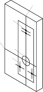
B. DOOR PREPARATION – E-PLEX EXIT TRIM
B-1 For New Installations (Existing Installations proceed
to Step B-2): Place paper template (e) (supplied) onto
the inside of the door and align with the Centerlines.
Mark the location of the E-Plex Exit Trim mounting
holes. Drill the four 3⁄8" (10 mm) (b) holes through the
door, then use a hole saw to cut the 21⁄8" (54 mm) (c)
bore through the door at the intersection of the
Vertical (a) and Horizontal (d)Centerlines. Care should
be taken to drill holes perpendicular to the door face.
Make sure any burrs are removed from the hole
edges, and that all chips are cleaned out of the holes
prior to installing hardware.
B-2 For Existing Installations (New Installations proceed to Section C):
Doors that have an existing exit device installed might already have a
through bore at the intersection of the Vertical and Horizontal
Centerlines, if the existing hole is smaller than 2 1⁄8" (54 mm) in diameter
it will need to be enlarged. Extra care should be used to ensure that the
location of this hole is kept as accurate as possible in relation to the exist-
ing mounting pattern. Place paper template (supplied) onto the inside of
the door aligned with the reference lines and mark the location of the E-
Plex Exit Trim mounting holes. Drill the four 3⁄8" ( 10 mm) holes through
the door, then use a hole saw to cut the 2 1⁄8" bore through the door at
the intersection of the Vertical and Horizontal Centerlines. Care should be
taken to drill holes perpendicular to the door face. Make sure any burrs
are removed from the hole edges, and that all chips are cleaned out of
the holes prior to installing hardware.
C. INSTALL EXIT DEVICE:
Follow the exit device manufacturer’s instructions for installing the exit
device onto the door.
a
d
e
c
b
7
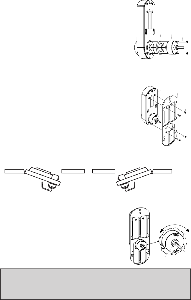
D. DOOR THICKNESS
The E-Plex Exit Trim Drive Unit (a) has a spring
loaded tailpiece (b) and is preassembled to accom-
modate standard door thickness from 1 3⁄4" to
approximately 2 1⁄8" for most applications. For
Doors up to 2 1⁄4" inches it may be necessary to
add a spacer to increase the projection of the tail-
piece. If this is required, first remove and discard
the two connecting screws (c) from the Drive Unit
(a). Add spacer (d), and remount using the two longer 1 5⁄8" (41 mm)
connecting screws supplied in the thick door accessory package.
E. ASSEMBLE OUTSIDE UNIT TO
UNIVERSAL MOUNTING PLATE
Assemble the Universal Mounting Plate (a) to the
Outside Unit Assembly (b) using the four 10-24 x 3⁄4"
long screws (c) supplied in the accessory kit.
F. LOCK HANDING
F-1 Determine the handing of your door, from the following diagram.
F-2 To set the handing of the drive unit grasp
the end of the tailpiece (a) with your fingers
and rotate the tail piece until it stops with
the indicator arrow (b) pointing at the
stamped letter “LHR” for left hand reverse
installations, or the stamped letter “RHR”
for right hand reverse installations.
Note: Until engaged with the exit device, the Tailpiece (a) is free to swivel 180
degrees to facilitate handing of the lock. During shipping and preparation the
position of the tailpiece may shift. The last step before mounting the lock unit
is to make sure the Drive Unit is set up for proper rotation.
Left Hand Reverse Right Hand Reverse
RHR
LHR
d
b
ac
c
a
b
b
a

KABA SIMPLEX®/E-PLEX®5x00 SERIES
LIMITED WARRANTY
Kaba Access Control warrants this product to be free from defects in material
and workmanship under normal use and service for a period of three (3) years.
Kaba Access Control will repair or replace, at our discretion, 5000 Series Locks
found by Kaba Access Control analysis to be defective during this period. Our
only liability, whether in tort or in contract, under this warranty is to repair or
replace products that are returned to Kaba Access Control within the three (3)
year warranty period.
This warranty is in lieu of and not in addition to any other warranty or condi-
tion, express or implied, including without limitation merchantability, fitness for
purpose or absence of latent defects.
ATTENTION: This warranty does not cover problems arising out of improper
installation, neglect or misuse. All warranties implied or written will be null and
void if the lock is not installed properly and /or if any supplied component part
is substituted with a foreign part. If the lock is used with a wall bumper, the
warranty is null and void. If a doorstop is required, we recommend the use of a
floor secured stop.
The environment and conditions of use determine the life of finishes
on Kaba Access Control products. Finishes on Kaba Access Control products
are subject to change due to wear and environmental corrosion. Kaba Access
Control cannot be held responsible for the
deterioration of finishes.
Authorization to Return Goods
Returned merchandise will not be accepted without prior approval. Approvals
and Returned Goods Authorization Numbers (RGA Numbers) for the 5000
Series are available through our Customer Service department in Winston-
Salem, NC (800) 849-8324. The serial number of a lock is required to obtain
this RGA Number. The issuance of an RGA does not imply that a credit or
replacement will be issued.
The RGA number must be included on the address label when material
is returned to the factory. All component parts including latches and strikes
(even if not inoperative) must be included in the package with return. All mer-
chandise must be returned prepaid and properly packaged
to the address indicated.
KABA ACCESS CONTROL
2941 INDIANA AVENUE
WINSTON-SALEM, NC 27199-3770
NO POSTAGE
NECESSARY
IF MAILED
IN THE
UNITED STATES
BUSINESS REPLY MAIL
FIRST-CLASS MAIL PERMIT NO. 1563
POSTAGE WILL BE PAID BY ADDRESSEE
WINSTON-SALEM, NC

Thank you for purchasing our product. In order to
protect your investment and to enable us to better
serve you in the future, please fill out this registration
card and return it to Kaba Access Control, or
register online at www.kabaaccess.com.
This lock will be used in what type of facility?
oCommercial Building oIndustrial / Manufacturing oAirport
oCollege/University oGovernment/Military oSchool/Educational
oHospital/Healthcare oOther (please specify)
What area is being secured with this lock? (e.g. Front Door, Common Door, Exercise Room)
This lock is:
oNew Installation
oReplacing a conventional keyed lock
oReplacing a Kaba Mechanical Pushbutton Lock
oReplacing a Kaba Electronic Access Control
oReplacing a Keyless Lock other than Kaba
How did you learn about Kaba Access Control Pushbutton Locks?
oAdvertisement o Previous Use oInternet / Web oAnother Use
oLocksmith oMaintenance oTraining Class oOther (please specify)
What was your reason for buying this lock?
Who installed your lock?
oLocksmith oMaintenance oOther
oCheck here if you would like more information on Kaba Access Control locks.
Name
Position
Company
Address
City
State ZIP (Postal Code) Country
Phone
Email
Name of Dealer Purchased From
Date of Purchase
Lock Model Number
REGISTRATION CARD

Notes
a
b
c
e
d
f
8
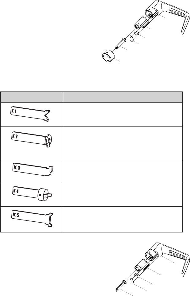
G. CHANGING KEY-IN-LEVER CYLINDER
On key-in-lever models of the E-Plex, the outside lever comes
preassembled with Kaba’s key-in-lever cylinder (Kaba 1599). To use a
different key-in-lever cylinder follow remaining steps in this section.
G-1 Remove KIL (key-in-lever) cylinder (a) from
the outside lever (b) by removing the outside
lever sleeve (f). Remove the cylinder insert
(e) and the rubber cylinder retainer (c) using
a small flat blade screw driver or small
needle nose pliers.
G-2 Determine the proper tailpiece (d)
from the chart below for your KIL
cylinder.
You must use a Kaba tailpiece. The K 2 tailpiece is preassembled with the
Kaba 1599.
G-3 Assemble the required tailpiece (d) (supplied) with
your KIL cylinder. All tailpieces must be installed
vertically (with key removed from cylinder)
for proper installation.
G-4 Insert the KIL cylinder into the outside lever
(b) and secure it with the cylinder retainer
(c) and the cylinder insert (e) until the KIL
cylinder is snug and unable to move freely.
Assa 65611, Australian: Kaba experT 107K5 &
Boyd KC286, Corbin-Russwin 2000-03, Kaba
1599, Schlage 23-001, Schlage Primus 20-760,
Kaba Peaks 1099
Medeco 20W200H1
Arrow C100, Sargent 10 LINE
Marks
Abloy 5277, Abloy 5477, Assa 65691,
Kaba 1539, Kaba Gemini 4730
KIL CYLINDERTAILPIECE
K1
K3
K2
K4
K5
b
a
c
e
d
9
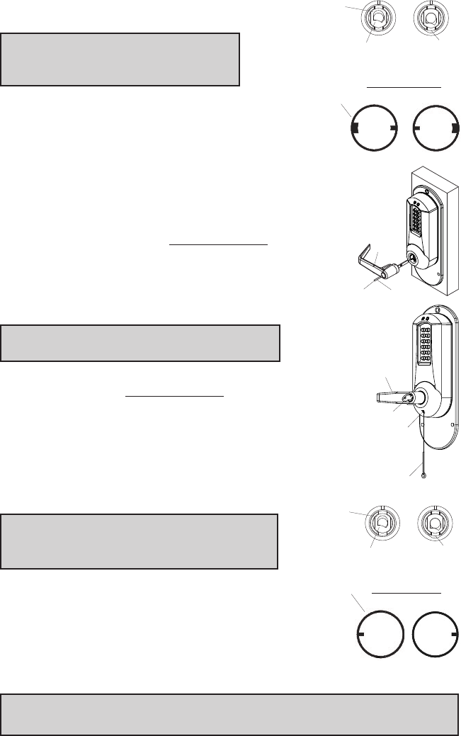
H. INSTALLING / REMOVING OUTSIDE LEVER
(Key-In-Lever models only, for interchangeable
and removable cores proceed to section I)
Note: Installing levers to the unit
assemblies before mounting the unit
assemblies may ease initial installation.
H-1 Make certain the lever catch is up as shown (c).
Position the lever sleeve (f) tab correctly with the
respective notch on the lever. The lock comes
shipped with the lever sleeve already installed in
the lock housing. When installing lever, ensure it is
oriented to engage the lever sleeve to accommodate
desired lock handing as shown.
H-2 Insert one of the (supplied) keys (a) into the outside
lever (b) and rotate key counterclockwise 45 degrees.
H-3 Insert the outside lever until it is flush to the outside
unit assembly. Secure the outside lever by rotating
the key clockwise 45 degrees to horizontal position.
Remove key.
Note: To remove the outside lever from the
outside unit assembly, follow the steps below.
H-4 Insert one of the (supplied) keys (a) into the outside lever
(b) and rotate it counterclockwise 45 degrees. Insert
release tool (d) into the small hole (e) under lever as
shown. Gently push lever catch up until it clicks.
Remove tool, then remove outside lever (b).
I. INSTALLING / REMOVING OUTSIDE LEVER
(Interchangeable / Removable Core Models)
Note: Installing levers to the unit assemblies
before mounting the unit assemblies may
ease initial installation.
I-1 Make certain the lever catch is up as shown (c).
Position the lever sleeve (f) tab correctly with the
respective notch on the lever. The lock comes shipped
with the lever sleeve already installed in the lock
housing. When installing lever, ensure it is oriented to
engage the lever sleeve to accommodate desired lock
handing as shown.
Note: For all interchangeable/removable cylinders except ASSA/Medeco/Yale,
proceed to section I-2. For ASSA/Medeco/Yale cylinders, skip to section I-5.
b
a
LH
KIL Lever Sleeve
RH
f
c
Correct
Position
Incorrect
Position
b
a
45º
c
Correct
Position
Incorrect
Position
e
d
RH
LH
IC Lever Sleeve
f
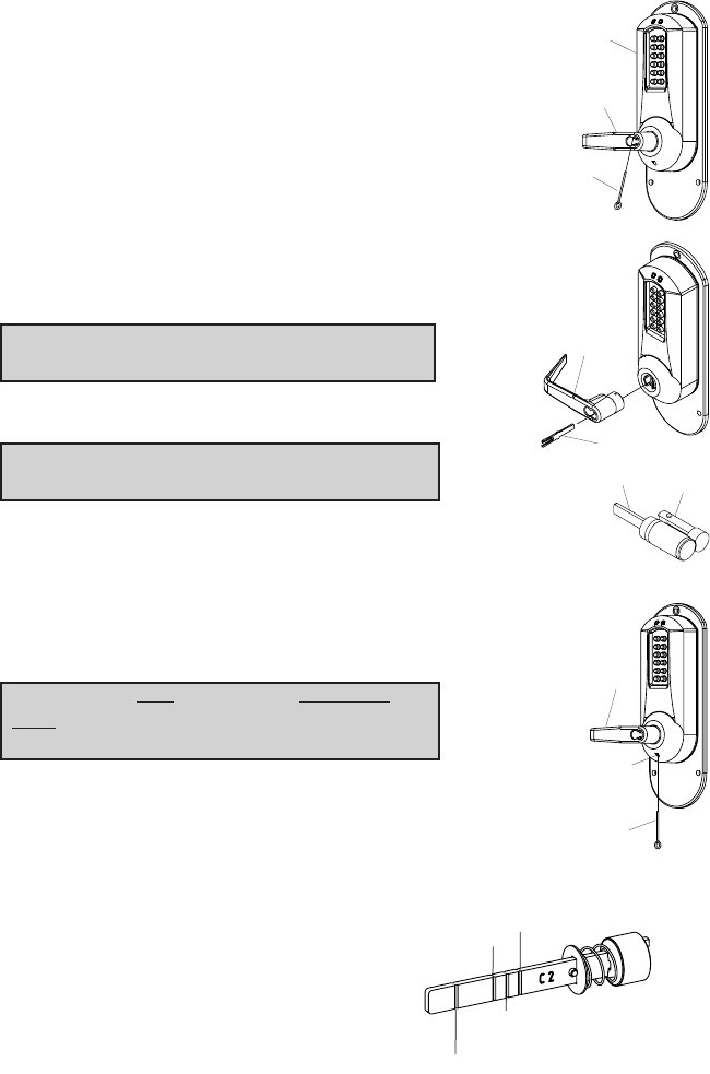
10
I-2 Insert the outside lever (b) until it is flush to the outside
unit assembly (a). To secure the outside lever, insert the
release tool (d) (or screwdriver) into the outside lever as
shown, and slide the lever catch down until it clicks. Make
certain lever is attached before installing the core.
I-3 Insert the supplied tailpiece (e) vertically into the outside
lever (b) as shown. Make certain that you rotate the tail-
piece so that it will align with the interchangeable core.
For screw cap type cylinders (Schlage) (g), the tail-
piece must be assembled to the cylinder first (vertical
position). Insert the interchangeable core into the
outside lever. Remove control key.
Note: To remove the outside lever from the
outside unit assembly, follow the steps below.
I-4 Remove the interchangeable core (g).
Then remove the tailpiece (e).
Note: You may want to use needle nose pliers
for some tailpieces.
Insert the release tool (d) into the small hole (f) under lever
as shown. Gently push lever catch up until it clicks. Remove
tool, then remove outside lever (b).
I-5 For ASSA/Medeco/Yale interchangeable/removable
cylinders, the tailpiece must be prepped for the desired
length before installation.
When using a Yale cylinder on a cylindrical
latch application, measure the door thickness
of the intended application.
I-6 Notice the score marks on the flat portion of the
ASSA/Medeco/Yale tailpiece. Using the diagram below,
locate the score mark on your tailpiece that matches your
cylinder prep for the intended application, and break the
tailpiece off accordingly.
b
e
g
vertical
d
b
a
b
f
d
YALE 6 & 7 PIN,
CYLINDRICAL – THIN DOOR
(1 3⁄8" (35 mm) to 1 1⁄2" (38 mm))
(DO NOT SHORTEN TAILPIECE -
For 1 5⁄8" (41 mm) to 2 1⁄4" (57 mm))
ASSA/MEDECO 5, 6 & 7 PIN,
CYLINDRICAL – DO NOT SHORTEN TAILPIECE
ASSA & MEDECO 6 PIN,
EXIT & MORTISE
MEDECO 5 PIN,
EXIT & MORTISE
YALE 6 & 7 PIN,
EXIT & MORTISE
11
I-7 Using two pairs of pliers, break the tailpiece to the desired length of the
intended application by holding one pair of pliers on the good side of the
score mark and a second pair on the other side of the score mark. Slowly
move the 2nd pair of pliers up and down until the unneeded portion of
the tailpiece breaks free.
I-8 Insert the Medeco tailpiece (e) vertically into the outside lever as shown.
Make certain that you rotate the tailpiece slightly so that it will align with
the interchangeable/removable cylinder. Insert the
interchangeable/removable cylinder into the outside lever.
Note: To remove the outside lever from the outside unit assembly, follow
steps below.
I-9 Remove the interchangeable/removable cylinder. Then remove the tail-
piece (e).
Note: You may want to use needle nose pliers for some tailpieces.
I-10 Insert the lever release tool (d) into the small hole (f) under lever as
shown. Gently push lever catch up until it clicks. Remove tool, then
remove outside lever (a).
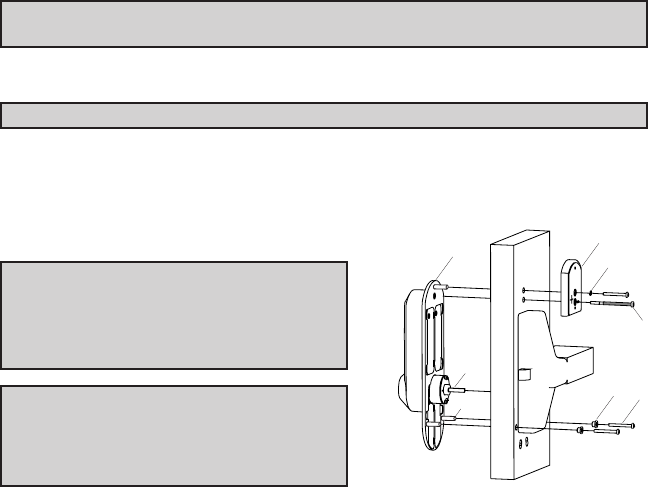
J. INSTALLING E5x00 EXIT TRIM
Note: Prior to mounting the lock,
ensure the handing is set correctly as
the tailpiece may have shifted during
handling (see section F).
Warning: If using a power drill, be
careful not to over-tighten as this could
cause damage to the mounting screws
and threads.
J-1 Guide the Unit Assembly so the Tailpiece (a) engages the vertical slot in
the hub of the exit device. The key override may be utilized to test the
operation to make sure that the tailpiece is engaged with the exit device
hub before fastening assembly to the door. The outside unit assembly
must be held in place by hand until fastened with LectroBolt.
J-2 Place the Battery Mounting Plate (b) on the door such that the red collar
is inside the lower of the top two 3⁄8" diameter holes and hold in place by
hand until fastened with LectroBolt.
J-3 Select the LectroBolt (c)(screw with red sleeve) length that corresponds
to the correct door thickness: use the 3" screw for thickness range from
13⁄4" to 2", for door thickness of 2 1⁄8" to 2 1⁄4" use the 3 1⁄8" long
LectroBolt included in the Thick Door Accessory pack.
d
e
a
fg
h
b
c
12
J-4 Insert the LectroBolt through the red battery mounting plate hole marked
with the lightning bolt symbol. For now, only partially tighten the
LectroBolt enough to hold the Outside Unit assembly and the battery
mounting plate in place on the door.
J-5 Insert the two Mounting Bushings (f) into the lower two holes on the
inside of the door.
J-6 Select the proper length Mounting Screws (g) for the door thickness: use
the 1 3⁄4" screw for door thickness range from 2 1⁄4" to 2", for door thick-
ness range of 2 1⁄8" to 2 1⁄4" use the 2 1⁄4" long screws included in the thick
door accessory pack. Insert two of the Mounting Screws into two lower
mounting holes and tighten securely.
J-7 Place the supplied lock washer (h) on the remaining mounting screw, and
insert in to the uppermost mounting hole and fasten securely to the sex bolt.
J-8 Important: Once the regular mounting screws have been tightened finish
tightening the LectroBolt™to secure the lock to the door.
Note: Do not shut door until installing batteries and testing operation as
outlined in the following two sections.
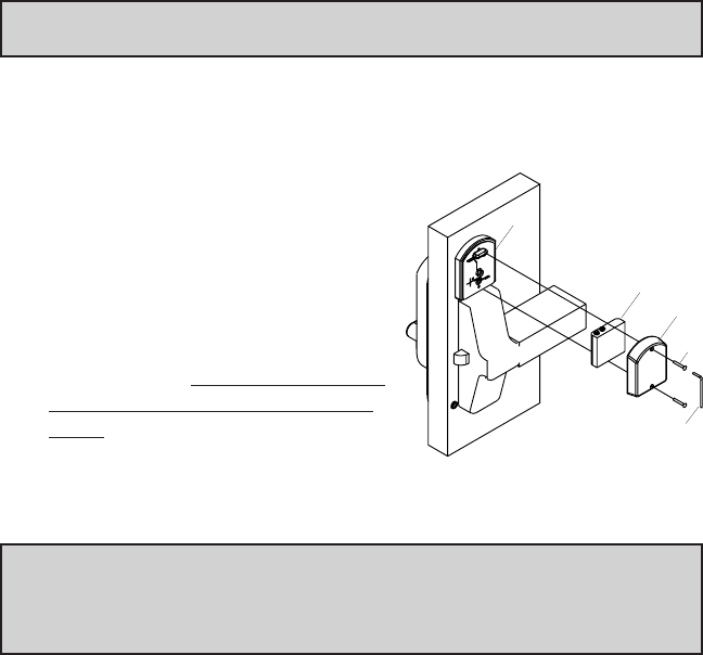
K. INSTALLING THE BATTERY PACK AND
COVER / CHANGING BATTERIES
K-1 To Install the Battery Pack (a) and
cover (b), snap the cable connector (c)
onto the top of the battery pack. Then
place the battery pack into the cover
with the terminals at the top. Put the
two security screws (d) into the cover
and fasten to the battery mounting
plate with the security screw wrench
(e). Important: Do not shut door until
testing operations as directed in sec-
tion L.
Caution: Over-tightening these screws could strip the threads in the housing or
crack the cover.
Warning: If the lock’s date and time have been set, and then power is
removed from the lock for more than 2 minutes, the lock’s current date
and time will need to be set again. Please refer to Lock Operations Manual
for instructions on setting the date and time.
K-2 To change batteries remove the two screws (d) from the battery cover (d)
using the security screw wrench (e) provided with your lock.
c
e
a
b
d
13
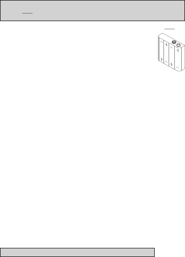
Warning: Do not install a 9V battery. This EPLEX lock operates on 4
alkaline only AA batteries (6V). A 9V will ruin the electronics in the lock
and void the warranty.
K-3 Remove the four depleted batteries and install four new alkaline (only) AA
batteries. Ensure that each battery is installed in the
proper direction as shown at the battery location in the
battery holder (a).
K-4 Reconnect the battery cable. Place the battery holder into
the cover. Screw the cover back onto the battery mounting
plate, and ensue the cable is not trapped under the edge of
the cover.
Caution: Over-tightening these screws could strip the threads in the housing or
crack the cover.
L. TESTING THE OPERATION OF THE LOCK
L-1 Depress the pushbar of the exit device and hold. Ensure that the latch is
fully retracted. Release the push pad; the latch should return to the fully
extended position.
L-2 Enter the factory set combination: 1,2,3,4,5,6,7,8. You see a green light
and hear a tone as you push each button. When the lock opens, you will
briefly hear the sound of an electric motor.
L-3 Rotate the outside lever downward and hold. Ensure that the latch is
retracted sufficiently to clear the strike. Release the Outside Lever; the
latch should be fully extended.
L-4 Allow a few seconds for the lock to re-lock (sound of motor is heard), and
then rotate the Outside Lever. The latch should not retract.
L-5 Insert one of the supplied keys into the outside lever. Rotate key counter
clockwise till it stops (approximately 90 degrees) then while holding the
key in this position with one hand, then use the other hand to rotate the
lever downward till it stops and hold (once the lever has rotated a few
degrees the key may be released). Ensure that the latch has retracted suf-
ficiently to clear the strike. Release the lever once more and ensure that
the latch is fully extended.
Note: Refer to the Operations Manual to set up lock operation.
14
M. PROGRAMMING AND SOFTWARE SETTINGS:
M-1 You must change the master Code from the factory default to another
code to program the lock. For further information on how to manually
program the E-Plex 3x00/5x00 Series Models, refer to the companion “E-
Plex 3x00/5x00 Operation Manual.” Software is required to program the
E3200/E5200 Series Locks.
M-2 When configuring the E3000/E5000 Series Locks using the optional
Standard Software, choose the box that contains “Entry Lock with
Passage (Cylindrical or Mortise without Deadbolt)” during lock setup.
M-3 When configuring the E3200/3700 and E5200/E5700 Series Locks
using the Enerprise Software, select the appropriate lock type during
lock setup.

15
Notes

Kaba Access Control
2941 Indiana Avenue
Winston-Salem, NC 27105 USA
Tel: (800) 849-8324 (336) 725-1331
Fax: (800) 346-9640 (336) 725-3269
www.kabaaccess.com PKG3055 0912
