Kaba Ilco 452 Deadlatch Instructions
User Manual: Kaba Ilco 452 Deadlatch Instructions Instructions
Open the PDF directly: View PDF ![]() .
.
Page Count: 2
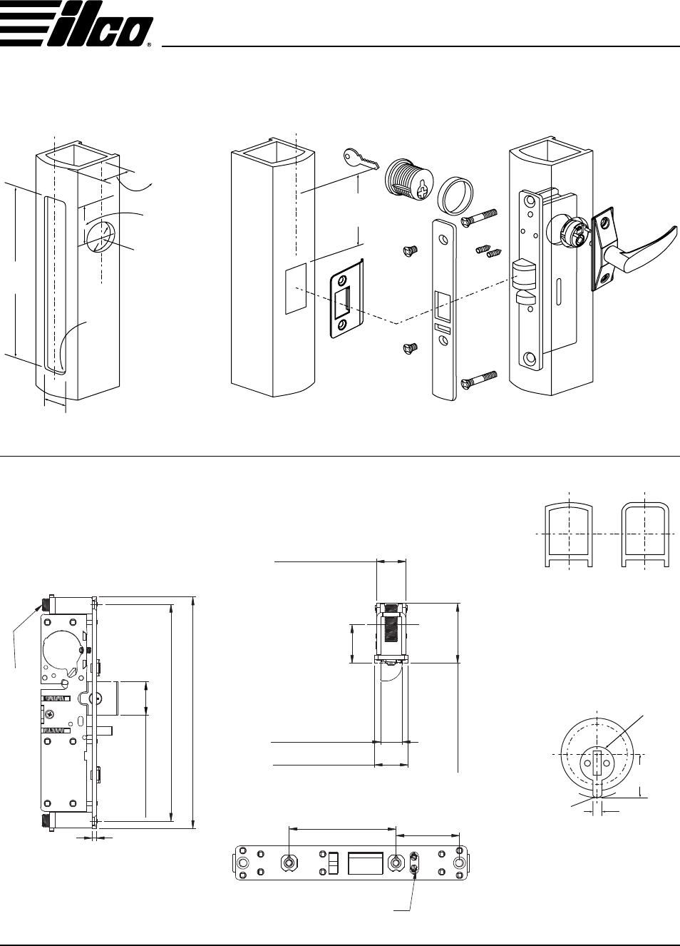
Dead Latch
452
C
L
LOCK & CYLINDER
INSTALLATION
BOLT CUTOUT
IN STRIKE
C
L
INSTALLATION
Door and Frame Installation
DIMENSIONS Inches
(Millimeters)
Stile Lock & Stile Stile Preparation
DIMENSIONS Inches
(Millimeters)
C
L
C
LC
L
RADIUS FLAT
± .005
± 0.13
C
L
C
L
CAM NO. "A"
CAM
TOLERANCE
These locks are operable
by any standard 15⁄32”
(29.37 mm) diameter
mortise cylinder with cam
dimensions as shown.
CUTOUT
TOLERANCE
+ 0.015
- 0.000
+ 0.38
- 0.00
Flat faceplates can be
adjusted for either right or
left hand bevelled doors.
Cylinder Cam
400 Jeffreys Rd., Rocky Mount, NC 27804 • Tel.: (252) 446-3321 • Fax: (252) 446-4702 • www.ilco.us
3.678” (162.0)
6.815” (173.1)
.984” (25.0)
.118” (3.0)
Alum. Set Screw
.898” (22.8)
Backset 11⁄8” (31.0)
“A” Dimension
1.78” (45.1)
.630” (16.0)
1” (25.4)
3.150” (80.0) 1.868”(47.5)
Set Screw
8-32 x 8 mm
BACKSET
1.6”
(40.7)
DIA HOLE
1.25”
(31.8)
6.89”
(175.0)
R.156”
(4.00)
(4)
1.010”
(25.65)
.875”
(22.2)
.80”
(20.4)
.18”
(4.6)
R .12”
R 3.0
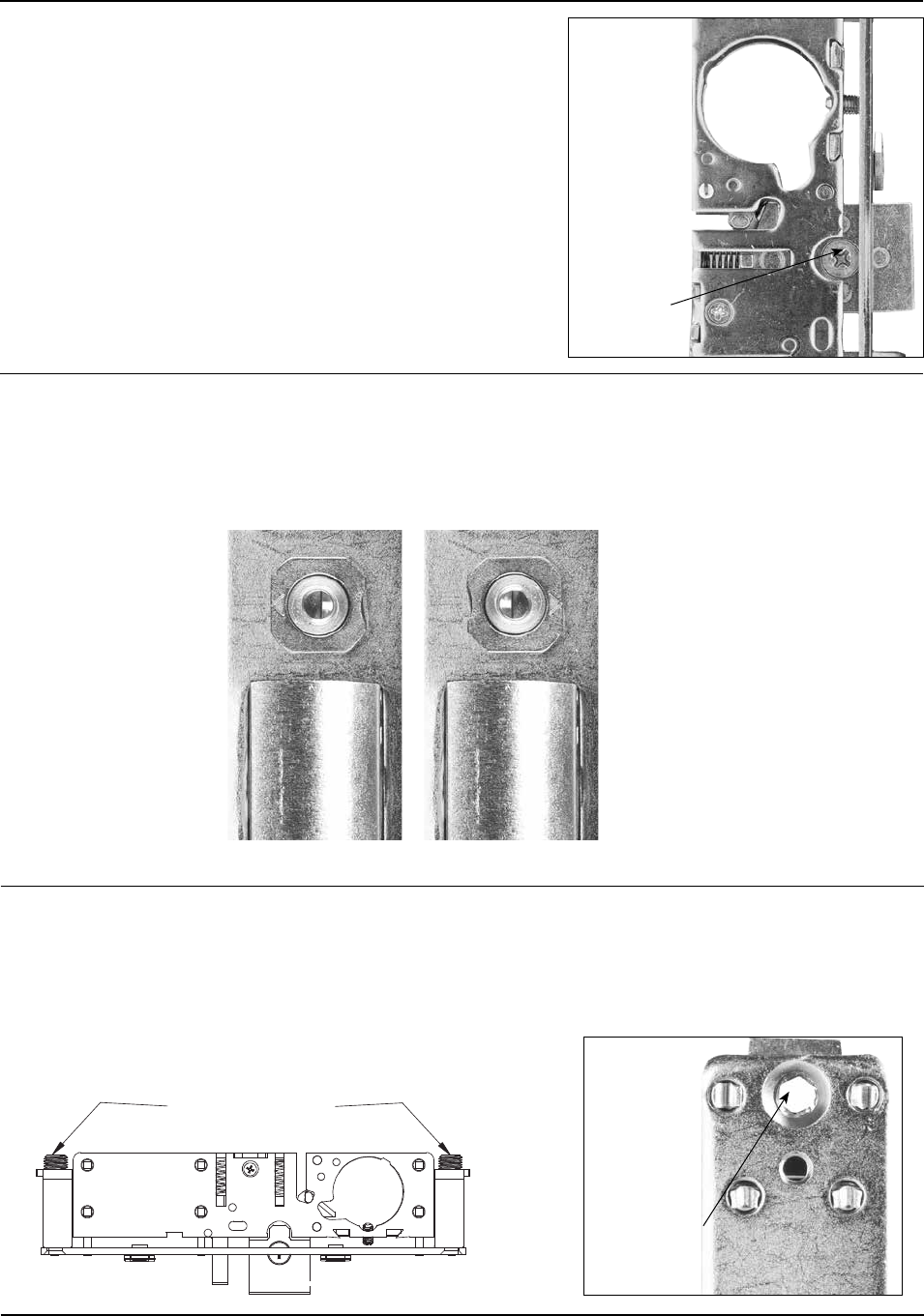
CHANGING HANDS
1. Push in latch bolt until the screw can be seen through the
latch case hole
2. Remove screw, rotate latch bolt to the other hand
3. Push in latch bolt until you see the counter sink hole on the
latch bolt
4. Install screw
Screw and latch
case hole
BEVEL TAB ADJUSTMENT
The bevel tabs allow the at faceplates to adjust to either left or right hand bevelled stiles. For radius face-
plates point the arrows towards the latch bolt.
RHR Bevel Position LHR Bevel Position
DEPTH ADJUSTMENT
Measure the depth from the back of the stile to the inside wall of the door edge. Equate the distance from
the face of the mounting plate to the end of depth adjusting tube spacers. Use a 3⁄16” (4.76 mm) hex key to
nd tune depth. Hex key size is the same as the one included in the 459 series push pull paddles.
Depth Adjusting
Tube Spacers
3⁄16” [4.75 mm]
hex here
Code No. 125991
