Kaba Ilco 58005900 RFID Card Reader User Manual System Analysis Firmware
Kaba Ilco Corporation RFID Card Reader System Analysis Firmware
User Manual
E-Plex 5900 Card Connect
Lock User Guide
(Beta Version, June 2007)
2/37
2
Statement according to FCC part 15.105
NOTE:
This equipment has been tested and found to comply with the limits for a Class B digital device,
pursuant to Part 15 of the FCC Rules. These limits are designed to provide reasonable protection
against harmful interference in a residential installation. This equipment generates, uses, and can
radiate radio frequency energy and, if not installed and used in accordance with the instructions, may
cause harmful interference to radio communications. However, there is no guarantee that interference
will not occur in a particular installation. If this equipment does cause harmful interference to radio or
television reception, which can be determined by turning the equipment off and on, the user is
encouraged to try to correct the interference by one or more of the following measures:
• Reorient or relocate the receiving antenna.
• Increase the separation between the equipment and receiver.
• Connect the equipment into an outlet on a circuit different from that to which the receiver is
connected.
• Consult the dealer or an experienced radio/TV technician for help.
Statement according to FCC part 15.21
Modifications not expressly approved by Kaba Ilco could void the user's authority to operate the
equipment.
Statement according to FCC part 15.19
This device complies with Part 15 of the FCC Rules. Operation is subject to the following two conditions:
(1) this device may not cause harmful interference, and
(2) this device must accept any interference received, including interference that may cause undesired
operation.
3/37
3
TABLE OF CONTENTS
1. INTRODUCTION ...............................................................................................................................................................5
1.1 SCOPE.............................................................................................................................................................................5
1.2 INTENDED AUDIENCE......................................................................................................................................................5
2. LOCK TYPES .....................................................................................................................................................................6
3. OPERATION MODES .......................................................................................................................................................6
3.1 FACTORY MODE..............................................................................................................................................................6
3.2 CONSTRUCTION MODE....................................................................................................................................................6
3.3 ACCESS MODE ................................................................................................................................................................7
3.4 BOOTLOADER MODE.......................................................................................................................................................7
4. USER ACCESS....................................................................................................................................................................8
4.1 ACCESS UNLOCK DURATION ..........................................................................................................................................8
5. PASSAGE MODE ...............................................................................................................................................................8
6. PRIVACY.............................................................................................................................................................................9
7. LOCKOUT MODE .............................................................................................................................................................9
8. TAMPER DETECTION.....................................................................................................................................................9
9. REMOTE UNLOCK (OPTION)......................................................................................................................................10
10. DOOR AJAR SENSING (OPTION)................................................................................................................................10
11. RESETTING THE LOCK TO FACTORY DEFAULTS..........................................................................................10
12. MECHANICAL KEY OVERRIDE.............................................................................................................................10
13. LOCK KEYPAD COMMANDS..................................................................................................................................11
13.1 ENTERING KEYPAD PROGRAMMING MODE ....................................................................................................................11
13.2 EXITING KEYPAD PROGRAMMING MODE .......................................................................................................................12
13.3 COMMANDS..................................................................................................................................................................12
14. MAINTENANCE UNIT (M-UNIT PDA) ...................................................................................................................15
14.1 SETTING DATE/TIME................................................................................................................................................... 16
14.2 SETTING THE COMMUNICATION KEY........................................................................................................................... 17
14.3 UPDATING THE FIRMWARE ...........................................................................................................................................18
14.4 PERFORMING DIAGNOSTICS ..........................................................................................................................................19
15. AUDIT LOGS................................................................................................................................................................19
16. QUICK LOCK CONFIGURATION...........................................................................................................................20
16.1 IN FACTORY OR CONSTRUCTION MODE.........................................................................................................................20
16.2 IN ACCESS MODE...........................................................................................................................................................20
4/37
4
17. QUICK LOCK UPDATE .............................................................................................................................................23
17.1 FIRMWARE UPDATE ......................................................................................................................................................23
17.2 BOOTLOADER UPDATE..................................................................................................................................................24
APPENDIX
……………………………………………………………………………………………………………..25
5/37
5
1. Introduction
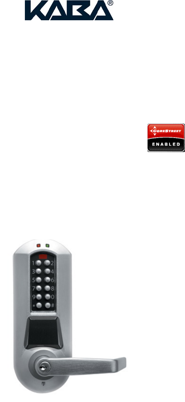
This document describes how to configure and use Kaba’s E-Plex 5900 stand-alone battery operated lock that
reads ISO 14443A compliant DESFire smart cards as user credentials enrolled in a “Card-Connected Access
Control System”. This “Corestreet Enabled” E-Plex 5900 lock functions as an integral part of a Card Connected
Access Control System granting access to users with valid credentials who were enrolled in a Card-Connected on-
line headend system.
For quick start, jump straight to the ‘Quick lock configuration’ and ‘the Quick lock update’ sections of the manual,
starting from page 19.
1.1 Scope
The document covers the initial lock setup, operation, keypad commands and usage including the use of the E-
Plex 5900 handheld Maintenance Unit (M-Unit) PDA which is also used to setup the lock.
1.2 Intended audience
This user guide was generated for use by internal Kaba engineering teams. For now this document will be used as
the E-Plex 5900 Card Connect Lock User Guide by the beta test customers during the beta test period as
reference.
6/37
6
2. Lock types
The E-Plex 5900 currently supports one of the two lock types with lock functions as:
Cylindical lock without thumbturn, supporting an “Entry” lock function.
Cylindrical or mortise lock with privacy thumbturn (with deadbolt for mortise), supporting a “Privacy” lock
function [** this model is for future offering only; currently not available “”]
The type of lock is configured through this access control system’s “Admin card” programmed by the on-line
headend system. Currently the E-Plex supports the DESFire card as user credential which is an ISO 14443A
compatible read/write RF card. It is important that the lock type be correctly setup at the outset because detection
of ‘door forced’ and ‘door open from inside’ conditions relies on it. The factory default of an E-PLex 5900 lock
function is “Entry” with the lock type being a cylindrical lock without a privacy thumbturn.
3. Operation modes
The lock operates in one of the following modes:
Factory
Construction
Access
Bootloader
3.1 Factory mode
Out of the box, the lock is in factory mode with a lock function as “Entry” and with an 8-digit PIN to open the lock as
12345678. This mode provides the operator with a known initial state. The operator can:
Unlock the lock by entering the default PIN on the keypad: 12345678
Change the default PIN
Validate the lock electronics hardware components
In this mode, only the factory default PIN of 12345678 will open the lock but not users’ DESFire cards.
3.2 Construction mode
Once the default PIN is changed, the lock enters construction mode. This mode is used until the lock can be
configured using an admin card (which requires the enrollment system to be in place at the headend access
control system). The operator can:
Unlock the lock by entering the new construction mode PIN on the keypad
Communicate with a maintenance unit (M-Unit) which is typically a Windows Mobile 5.0 compatible
handheld PDA, using the default communications key (16 zeros) to access the following functionalities:
o Set the date/time, daylight saving time info and time zone
o Update the bootloader
o Update the firmware
Use one of the following lock keypad commands
o Change PIN
7/37
7
o Set date and time
o Set passage mode
o Configure the lock using an admin card
o Set lockout
o Run diagnostics and display various states of the lock
o Enter communication mode
Reset the lock to factory mode
In the construction mode user cards will not be recognized by the lock.
3.3 Access mode
Once the lock is configured using the admin card, the lock enters the “card connect” access mode and the
construction PIN will not work anymore. In this mode the user can:
Unlock the lock by presenting a valid credential (an ISO 14443A compliant DESFire card or optionally
entering a user PIN followed by the card).
Communicate with the maintenance unit using the configured communication key to access the following
functionalities (requires maintenance unit privilege):
o Set the date/time, daylight saving time info and time zone
o Update the bootloader
o Update the firmware
Use one of the following keypad commands
o Set date and time (requires keypad programming privilege)
o Set passage mode (requires passage mode privilege)
o Configure the lock using an admin card (requires admin card privilege)
o Set lockout (requires lockout privilege)
o Perform diagnostics and display lock’s various states (requires lock keypad programming
privilege)
o Enter communication mode (requires maintenance unit privilege)
Reset the lock to factory mode
In this mode cards are required to unlock the lock.
3.4 Bootloader mode
The bootloader mode is a transition mode when updating the lock firmware. Before starting a lock firmware
update, the lock automatically switches to this mode. It remains active until a new firmware is fully received by the
lock. Should the firmware upload be interrupted (communication failure), the lock remains in bootloader mode.
Whenever a key is pressed, the green and red leds will blink sequentially while waiting for a maintenance unit
connection. If no connection is established within 15 seconds, the leds are turned off and the lock waits for
another key press.

8/37
8
4. User access
The following table lists the different user access methods depending on lock mode. On granted access, the
green led will turn on with a high pitch sound. When access is denied, the red led is turned on with low pitch
sound. Take note that a pin can be cleared by pressing the * key.
Mode Method
Factory Press the following key sequence:
12345678
Construction Press the following key sequence:
XXXXXXXX
Where:
XXXXXXXX is the 8 digit construction pin (see ‘Quick lock configuration’ section
or ‘Keypad programming’ section
Access In “card connect” access mode, access requires a card to be presented (< half an inch)
in front of the lock housing where the black antenna unit is installed. The lock can be
configured so that the credential is either pin followed by card, or card only mode
(configuration from the admin card, programmed by the headend system).
If the lock is configured in pin and card mode:
1. Type in pin
2. Present card
If the lock is configured in card only mode:
1. Present card
Note that in card only access, the lock allows the user to enter his pin first also as in pin
and card access mode.
4.1 Access unlock duration
When a user accesses a lock, the lock unlocks for a period of time defined by:
Standard unlock duration if user does not have the ADA privilege (Disabilities Act)
Extended unlock duration if user has ADA privilege (Disabilities Act)
These unlock durations are configured using the admin card which is programmed by the headend system.
Note that the ADA privilege is set on the user card by the headend system.
5. Passage mode
Passage mode is used to keep a lock unlocked for a given period of time and no credential is needed to access.
The lock is set in passage mode when a user with ‘passage mode’ privilege enters the ‘activate passage mode’
keypad command. The lock remains unlocked until:
The configured passage mode duration expires (from admin card),
Temporary duration, specified in same keypad programming session, expires.
9/37
9
The passage mode activation period (start & end times) is set when the passage mode is first activated. Any
deactivation/reactivation of the passage mode during the activation period does not reset the expiration (end time).
However, if a new temporary duration is set in the same keypad programming session as a reactivate passage
mode command, the expiration is modified.
Eg. if passage mode is activated at 1:00 and the configured duration is 5 hours, the lock will relock at 6:00 even if
passage mode was deactivated and reactivated several times in the 1:00-6:00 period. However, during the 1:00-
6:00 period, if a new temporary duration is set followed by a reactivation command (in the same keypad
programming session), a new expiration is set. E.g. at 2:00, set temporary duration to 1 hour and in the same
keypad programming session reactivate the passage mode, the lock will relock at 3:00 instead of 6:00.
This feature can also be used to temporarily extend the passage mode period.
6. Privacy (** for future offering only **)
Privacy enables any user to prevent other users from unlocking a lock (unless they have the ‘privacy override’
privilege). Turning the thumbturn in the horizontal position activates privacy and locks the lock. Privacy activation
deactivates passage mode and also locks the lock.
The privacy unlock option must be marked as ‘enabled’ in the admin card programmed by the headend, otherwise
the lock does not respond to the thumbturn.
7. Lockout mode
Lockout mode enables a privileged user to lock the lock and prevent any other cardholder to unlock it (unless they
have the privilege to deactivate the lockout).
Lockout is activated:
Using a keypad command (requires cardholder ‘lockout privilege’)
Using the mechanical key override
Lockout is deactivated:
Using a keypad command (requires cardholder ‘lockout privilege’)
By inserting and turning the mechanical key and unlock.
8. Tamper detection
Tamper detection helps preventing users from guessing access pins of other cardholders. Tamper detection is
controlled using two parameters configured by the headend on the admin card:
Tamper count: allowed number of consecutive incorrect pin or card input
Tamper shutdown time: time during which attempts to unlock the lock are denied.
Tamper shutdown is activated:
By entering, consecutively, incorrect pin or card more than the configured ‘tamper count’.
Tamper shutdown is deactivated:
By inserting and turning the mechanical key and unlock.

10/37
10
9. Remote Unlock option (*must be installed to operate*)
If installed, the remote unlock option enables users to unlock the lock with a normally open, momentary on/off
switch. This switch is connected to the remote unlock connector inside the lock by a 24 AWG gage twisted pair
wire up to about 100 feet in length The remote unlock option must be marked as ‘enabled’ in the admin card
programmed by the headend system, otherwise the lock will not respond to the remote unlock switch.
When enabled, remote unlock can be used to unlock the door during:
Tamper shutdown
However it will not unlock the lock:
During lockout
[When privacy is enabled for privacy locks; ** future**]
10. Door Ajar Sensing option (*must be installed to operate*)
If installed, the door ajar sensing option senses the door opened (and then door closed) status when opened from
outside (ingress); and also the door opened status when opened from inside (egress). In either case the door ajar
events are audited in the lock’s memory and passed on to the headend system via the admin card as logged
entries. In factory mode only, the lock will also visually indicate occurrences of these events: an alternate red and
green flash sequence for an egress, a double green led flash when door is opened from outside and a double red
led flash when it is closed.
11. Resetting the lock to factory defaults
The lock can be reset to factory defaults at any time by following this procedure. Warning: When a hard reset like
this is performed, all newly programmed lock configuration parameters, user access privilege policies etc will be
erased from the lock memory and the lock will default to the factory default lock parameters and the factory default
PIN of 12345678. However, the current date & time will not be altered.
1) Insert and turn mechanical override key to retract latch and hold,
2) Press key ‘#’ and release key override within 5 seconds
3) While red and green led flash alternately, press sequence ‘12345678#’ (if successful, green led
flashes twice with high pitch beep) and the lock is reset to factory defaults.
Note that audit logs are not erased by this procedure.
12. Mechanical key override
The key override is used to:
Mechanically unlock the lock (insert and turn the key to retract the latch)
Reset the lock to factory defaults (see ‘Resetting the lock to factory defaults’ section)
Reset tamper shutdown (see ‘Tamper shutdown’ section)
Deactivate lockout (see ‘lockout mode’ section)

11/37
11
13. Lock keypad commands
Using keypad commands, a user can do maintenance operations on the lock.
The following table lists the modes and available commands.
Mode Commands
Factory Only one command is available in factory mode:
Set construction mode pin
Construction All commands, without any restriction, are available in factory mode:
Set construction pin (in factory or construction mode)
Configure lock using an admin card
Set date
Set time
Set temporary passage mode duration
Activate/deactivate passage mode
Activate/deactivate lockout
Perform diagnostics
Identify the lock model
Start a maintenance unit communication session
Access All commands with the exception of ‘Set construction pin’ are available IF the related
privileges are granted (see table below).
The following table lists the privileges required to access keypad commands. These privileges are REQUIRED
once the lock is configured (using an admin card). Important: The privileges must be assigned on the headend
system and stored on user cards.
Privilege Command
Keypad programming Set date
Set time
Perform diagnostics
Identify the lock model
Lockout Activate/deactivate lockout
Maintenance unit
programming
Start a maintenance unit communication session
Passage mode Set temporary passage mode duration
Activate/deactivate passage mode
Admin card configuration Configure lock using an admin card
13.1 Entering keypad programming mode
Keypad programming mode is entered differently, depending on the current operation mode. Start the keypad
programming mode by pressing the # key followed by PIN #, if the lock is in construction mode, for example. The
12/37
12
commands are then entered by pressing 3 numbers pertaining to the command code followed by a #. Then,
depending on the command, one or more parameters are entered, separated by # keys. The # key acts as a
confirmation (like an “Enter” key on a PC keyboard). Finally, press the # key again to exit the keypad programming
mode:
# Command# parameters# parameters# … #
Example of a complete command sequence: To set date (001 command code) & time (002 command code),
assuming 87654321 is the construction PIN, and the date and time you are setting is June, 19th 2007, 1:30PM):
# 87654321# 001# 061907# 061907# 002# 1330# 1330# #
Maximum 5 seconds are allowed between key presses and a maximum of 15 seconds between command
sections. Note that the * key can be used to clear the current parameter or command. The following table lists the
different methods of entering in keypad programming mode:
Mode Procedure
Factory Enter the factory default pin by pressing the keys in the following sequence:
#12345678#
Construction Press the keys in the following sequence where the PIN must be 8 digits in length:
#PIN#
Where PIN is the construction pin which must be different from the factory pin.
Access If the lock was configured for pin and card, enter the following sequence:
1. #PIN#
2. Present card
Where PIN is the cardholder pin (anywhere from xx to 20 digits?)
If the lock was configured for card only, enter the following sequence:
1. #Present card
13.2 Exiting keypad programming mode
To exit keypad programming after a command was entered, do one of the following:
Leave the lock idle for 5 seconds. Red led will turn on with low pitch tone, or
Press the # key. Green led will turn on, followed with 2 high pitch beeps.
13.3 Commands
The following table list the lock keypad commands recognized by the lock. Remember that privileges are required
to access commands once the lock is configured. If the cardholder does not have the required privilege to access
a command, the red led is turned on. Once a command is entered successfully, the green led will turn on with high
pitch sound (same for its parameters). If the command is executed successfully, the green led is turned on with 2
high pitch beeps.
Name Command keys Parameters
Set construction pin 000# XXXXXXXX#XXXXXXXX#

13/37
13
Where:
XXXXXXXX is the 8 digit construction pin, entered twice
(0-9)
Set date 001# MMDDYY#MMDDYY#
Where:
MM is the month (01-12)
DD is the day (01-31)
YY is the year (07-99)
Note that the date is expressed in local time.
Set time 002# HHMM#HHMM#
Where:
HH is the hour (00-23)
MM is the minute (00-59)
Note that the time is expressed in local time and in 24-hour time
format.
Set temporary passage
mode duration 005# HH#
Where:
HH is the number of hours the lock should be in passage mode
(00-24). A value of 00 will abort the passage mode.
Configure lock using an
admin card 100# (None), just present the card.
No # is required after presenting the card.
Activate/deactivate
passage mode 399# A#
Where:
A is 1:activate or 0:deactivate
Activate/deactivate
lockout 499# A#
Where:
A is 1:activate or 0:deactivate
Perform diagnostics 500# None.
When this command is entered, the following operations are
done:
The green led turns on for 2 seconds with a high pitched
sound and then,
The red led turns on for 2 seconds with alow pitched
sound
Then the user must press keypad keys in this exact
sequence: 1 2 3 4 5 6 7 8 9 0 * #
For each successfully pressed key, the green led turns on with a
high pitched sound. But if a wrong key is pressed or a pressed
key is not detected, the red led will turn on with a low pitched
sound indicating a problem with the lock electronics..
Identify lock model 501# None.
When this command is entered, the lock identity green and red
led indicators are enabled (blink 9 times to indicate E5900

14/37
14
model).
Start a maintenance unit
communication session 900# None.
The red and green leds blink in alternate sequence indicating
ready for communications with the M-Unit until one of the
following occurs:
No connection is established during a 15 seconds period
Communication is closed by the maintenance unit
15/37
15
14. Maintenance unit (M-Unit PDA)
The E-Plex 5900 M-Unit is a Windows Mobile 5.0 compatible handheld PDA running Kaba’s E-5900 M-Unit
software. The M-Unit is utilized for occasional interaction with the locks on-site and day to day operation of the lock
is possible without the M-Unit. Please refer to the “Appendix” section at the end of this document on how to install
the “E-Plex 5900 M-Unit” software application on your Windows Mobile PDA.
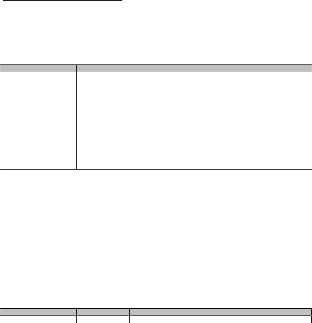
The E-Plex 5900 M-Unit can be used to perform the following functions:
Setting Date/Time Parameters
Setting Communications Key
Updating Lock Firmware
Performing Lock Diagnostics
Important: The communication between the lock and the PDA is via the IrDA (infra-red) interface. Hold and point
the M-Unit to the lock so that the small dark red infra-red glass windows of both devices face each other straight at
a distance of between 4 and 8 inches for successful communication – see the picture on the right below.
These functions are all available from the main M-Unit program menu, displayed when the application is run:
16/37
16
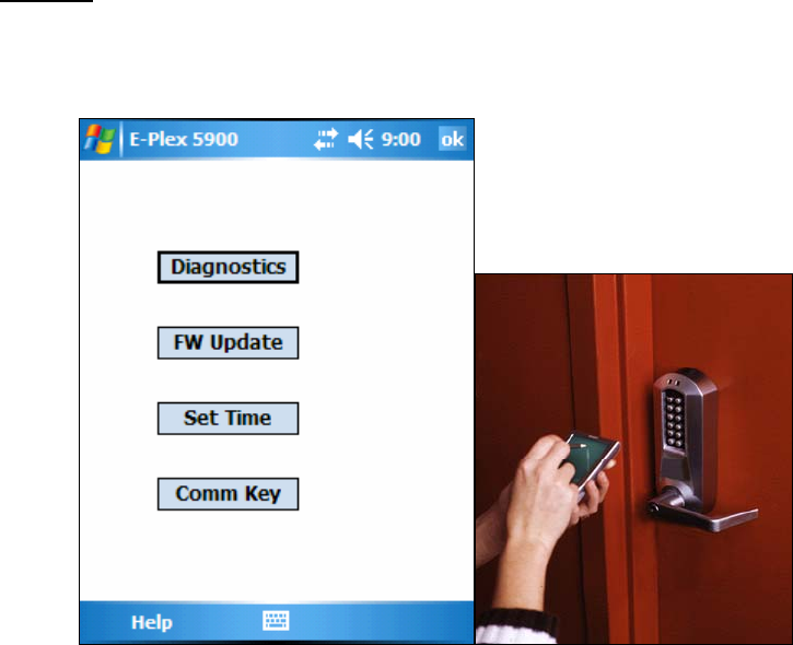
14.1 Setting Date & Time
When the Set Time function is invoked, the following page is displayed:
This screen dialog is used to configure and send to the lock all of the following data:
• Whether or not DST is to be used in this lock
• Start time of DST
• End Time of DST
• DST Offset (how far we adjust the clocks on a DST shift)
• Local Time Zone. This is the difference between local standard time and UTC, and is not adjusted for
DST.(Example: set “-5” for Eastern Standard Time)
When this function is activated, the application will display the last saved settings, if they can be found. If no saved
settings are available (the data file was deleted or the settings were never saved), default settings will be
displayed. Note that if DST is unchecked, the fields that pertain to DST will be disabled. The last saved data will be
displayed, but will not be sent to the lock. Click on “Send” button to send the current date & time to the lock.
17/37
17
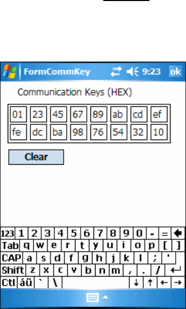
14.2 Setting the Communication Key
The Communication Key is used as a customer unique security key comprising a sequence of hex numbers. This
key is transferred in the lock (through the Admin card), and will be sent by the M-Unit to the lock at the beginning
of each communication session. This ensures that only a person knowing the key value in the lock can interact
with the lock using the M-Unit. Important: The key is not generated by the M-Unit application itself but by the
headend system and the M-Unit operator must enter these numbers at the initial M-Unit setup. The M-Unit will
simply pass these pre-set values to the lock in order to enter communication with the lock.
When the Communication Key selection is made, the M-Unit screen will display the last saved set of key values:
If no key values have been saved, the boxes will be filled with all zeros. Use the “Clear” button to empty all fields
and begin typing in new required values. If the boxes are initially empty, the focus will automatically jump to the
next box as each one is filled, thus facilitating rapid entry of new keys.
18/37
18
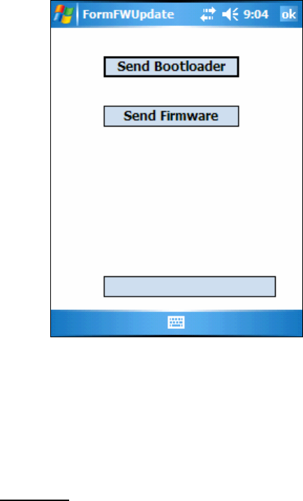
14.3 Updating the Lock Firmware
There exist two separate files that the M-Unit can upload to the lock. One is the “bootloader” and the other is the
lock “firmware” itself. The bootloader is a separate small program that is invoked to replace the E-Plex 5900
firmware file in the lock. The normal procedure is to first replace the bootloader, and then the firmware file.
However, if the operator knows that there is no change to the bootloader, it is perfectly acceptable to simply
update the firmware file using the existing bootloader.
Important: In order to perform a firmware upload the lock must be placed under control of the bootloader. This
means that after starting communication, the lock will beep and shut down for a few seconds. You must not move
the M-Unit away from the lock during this period. After approximately two seconds the M-Unit will begin
communicating again with the lock, and will proceed to upload the new firmware file. On completion of this transfer,
the lock will reboot and activate the new firmware.
19/37
19
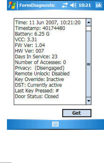
14.4 Performing Diagnostics
The M-Unit can query the lock for a collection of useful status info from the lock including a validity check on the
lock electronics, green and red leds and the buzzer. Click on “Get” to display the results:
The Diagnostics will repeat in a continuous loop until it is stopped either by removing the M-Unit PDA from the lock
vicinity or by selecting the “Stop” button. This loop function is useful for verifying all the keys on the lock keypad
etc. [Note: The current beta version of the M-Unit software will only take a “snapshot” of the diagnostics status
once and will display it as shown above. There is no “Stop” button and no continuous loop diagnostics at this time].
15. Audit Logs
The E-Plex 5900 keeps a log entry for every transaction or event encountered in its memory. The audit log entries
are stored in a circular list, where newer ones overwrite older ones. Events like any DESFire card user access,
passage mode on/off status etc are logged and transferred to the headend system automatically. Note that audit
og entries in the lock are never erased from the lock; the only time an audited event gets erased is when it is
overwritten by a more recent event when the lock audit buffer is full. The lock can store up to 30,000 audits. For
the beta version, only the last 10 audit events can be stored on a user’s card to be read on the headend system
later; however, in the final version all 30,000 audited events can be transferred to the M-Unit to be processed at
the headend system.

20/37
20
16. Quick lock configuration
The following tables describe the sequence of commands required to configure the lock from factory,
construction and access mode. Note that:
o Typically a timeout of 5 seconds applies to key presses and card detection. After this delay, the
current operation is cancelled (red led turns on along with low pitch sound).
o Keypad commands are always followed by a ‘#’ key.
16.1 In Factory or Construction mode
Step Sub Description/Operation Notes
1 Reset the lock to factory mode
1 Insert and turn mechanical key in key
cylinder to retract latch and hold Note: Resetting the lock to factory defaults
can be done while in any mode -> factory,
construction or access.
2 Press and release ‘#’ key on lock keypad
3 Release mechanical key Once done, red and green led leds blink in
alternate sequence
4 Enter reset command:
o 12345678# Once done, green led blinks with high pitch
sound indicating successful operation
2 Enter lock keypad programming. Programming mode is entered by pressing
the ‘#’ key followed by the default PIN and
then pressing ‘#’ again. Any command will
exit back to keypad programming mode if
the lock is idle for 5 seconds. The keypad
programming mode is itself exited when no
key is pressed for 5 seconds.
1 Enter keypad programming mode by
typing:
o #12345678#
Green led and high pitch sound on success.
3 Change default (factory mode) PIN Must change default pin to enter
construction mode.
1 Enter the change PIN command:
o 000#
2 Enter the new (construction mode) PIN:
o XXXXXXXX# The construction PIN is always 8 digits.
3 Enter the new PIN AGAIN:
o XXXXXXXX# Once entered, the green led turns on with a
high pitch on success.
4 Prepare the maintenance unit (M-Unit)
1 Start the E-Plex 5900 M-Unit application
on the PDA
2 Select ‘Comm key’ option
3 Enter the communication key (16 zeros
by default) and select ‘ok’ Upon factory reset, the communication key
is set to 16 zeros.
4 Select the ‘Set Time’ option and set the
date/time related parameters. Important: It is extremely important that the
date/time be set correctly. The date, time
and time zone must be set properly because
the card-connected credentials rely on them.
Once in access mode, invalid time settings

21/37
21
prevent user credential validation and so the
lock will deny access to keypad
programming modes (like date/time setting).
5 1 Enter communication mode by typing:
o 900# The green led blinks with high pitch sound to
confirm the command and then red and
green leds blink in alternate sequence to
indicate communication mode is activated.
The communication with the maintenance
unit must be established within 15 seconds
2 Click ‘Send’ on the maintenance unit ‘Set
Time’ dialog Once the time is set, an ‘ok’ dialog box will
be displayed and the lock will respond with a
high pitch sound.
6 Configure the lock using the admin card
1 Enter the lock configuration command
(where valid users will be transferred to
lock via the Admin card):
o 100#
The green led will blink to indicate that it is
waiting for the Admin card.
2 Present the Admin card to the lock Once the lock reads and processes the
Admin card, the green led will turn on with a
high pitch sound indicating success.
[After exiting the keypad programming mode
as shown on the next step, the lock is now in
(user credential) access mode. A valid ISO
14443A DESFire user card will now operate
the lock].
7 Exit keypad programming mode Either exit pressing the ‘#’ key or leave the
lock idle for five seconds. In the latter case,
the red led turns on with a low pitch sound to
indicate a timeout.
1 Press ‘#’ key Green led blinks with high pitch sound
16.2 In Access mode
Step Sub Description/Operation Notes
1 Enter lock keypad programming.
1.1 Start keypad programming mode
o Press ‘#’ key
1.2 If the lock is configured for PIN and card:
o Type in PIN
o Press ‘#’ key
1.3 Present a valid user card having ‘update
using admin card’ privilege to the lock If programming mode is entered, the green
led turns on along with a high pitch sound.
2 Configure the lock using the admin card
1 Enter the lock configuration command
(where valid users will be transferred to
lock via the Admin card):
o 100#
If the user does not have the ‘update using
admin card’ privilege, access will be denied
(red led low pitch sound). The green led will
blink to indicate that it is waiting for the

22/37
22
admin card.
2 Present the admin card to the lock Once the lock reads and processes the card,
the green led will turn on with a high pitch
sound indicating success.
[After exiting the keypad programming mode
as shown on the next step, the lock now
goes back to (user credential) access mode.
A valid ISO 14443A DESFire user card will
now operate the lock].
3 Exit keypad programming mode Either exit pressing the ‘#’ key or leave the
lock idle for five seconds. In the latter case,
the red led turns on with a low pitch sound to
indicate a timeout.
1 Press ‘#’ key Green led blinks with high pitch sound

23/37
23
17. Quick Lock Update
Occasionally the lock firmware and/or bootloader will require updates. A Windows Mobile 5.0 compatible
PDA running Kaba’s E-Plex 5900 M-Unit application is used to upload new firmware to the lock. When a
firmware update is requested, the lock switches to bootloader mode. The lock will remain in bootloader
mode until a valid firmware is completely uploaded and will only process the maintenance unit (M-Unit)
commands to upload the firmware. The lock does not process any keypad input or unlock/lock commands.
Note that in bootloader mode, the lock starts a communication session whenever any key is pressed on the
lock keypad.
17.1 Firmware update
Step Sub Description/Operation Notes
1 Prepare the maintenance unit
1 Start the E-Plex 5900 application
2 Select ‘Comm key’ option
3 Enter communication key and then select
‘ok’ If the lock is not yet configured with an
admin card, the key is set to the default
value of 16 zeros. Otherwise, the key is
whatever value was configured in the admin
card.
4 Select the ‘FW update’ option
2 Set the lock in communication mode.
1 From construction mode
1.1 Enter keypad programming mode by
pressing ‘#’ key followed by PIN and ‘#’:
#XXXXXXXX#
1.2 Enter communication mode by typing:
o 900# The green led blinks with high pitch sound to
confirm and then red and green blink in
alternate sequence to indicate
communication mode is activated.
The communication with the maintenance
unit must be established within 15 seconds
1.3 Skip to step 3
2 From access mode
2.1 Start keypad programming mode
o Press ‘#’ key
2.2 If the lock is configured for PIN and card:
o Type in PIN
o Press ‘#’ key
2.3 Present a user card having ‘maintenance
unit’ privilege to the lock If programming mode is entered, the green
led turns on along with a high pitch sound.
2.4 Enter communication mode by typing:
o 900# If the user does not have the ‘maintenance
unit’ privilege, access will be denied (red led
low pitch sound). The green led blinks with
high pitch sound to confirm and then red and
green blink in sequence to indicate
communication mode is activated.

24/37
24
The communication with the maintenance
unit must be established within 15 seconds
2.5 Skip to step 3
3 From bootloader mode
3.1 Press any key The green led blinks with high pitch sound to
confirm and then red and green blink in
sequence to indicate communication mode
is activated.
The communication with the maintenance
unit must be established within 15 seconds
3.2 Skip to step 3
3 Start firmware upload
1 On the maintenance unit press ‘Send
firmware’ Firmware updates takes nearly 4 minutes.
The progress bar will display how much data
is transferred.
Once completed, a ‘done’ message will be
displayed on the maintenance unit. The lock
is now in firmware mode and ready for use.
Should the lock reply with an ‘Invalid
bootloader’, the bootloader must first be
updated.
17.2 Bootloader update
The bootloader can only updated when the lock firmware is running (thus not in bootloader mode).
Step Sub Description/Operation Note
1 Ready maintenance unit
1 Start the E-Plex 5900 application
2 Select the ‘FW update’ option
2 Set the lock in communication mode.
1 From construction mode
1.1 Enter keypad programming mode by
typing ‘#’ key followed by PIN and ‘#’:
#XXXXXXXX#
1.2 Enter communication mode by typing:
o 900# The green led blinks with high pitch sound to
confirm and then red and green blink in
sequence to indicate communication mode
is activated.
The communication with the maintenance
unit must be established within 15 seconds
1.3 Skip to step 3
2 From access mode
2.1 Start keypad programming mode
o Press ‘#’ key

25/37
25
2.2 If the lock is configured for PIN and card:
o Type in PIN
o Press ‘#’ key
2.3 Present a user card having ‘maintenance
unit’ privilege to the lock Without the privilege, access will be denied.
If programming mode is entered, the green
led turns on along with a high pitch sound.
2.4 Enter communication mode by typing:
o 900# The green led blinks with high pitch sound to
confirm and then red and green blink in
sequence to indicate communication mode
is activated.
The communication with the maintenance
unit must be established within 15 seconds
2.5 Skip to step 3
3 Start bootloader upload
1 On the maintenance unit press ‘Send
bootloader’ Bootloader update takes a few seconds to
complete. The progress bar will display how
much data is transferred.
Once completed, a ‘done’ message will be
displayed on the maintenance unit.. The
lock is ready for use.
Kaba Access Control Tech Support
Phone: 800-849-8324, or 336-725-1331 x400
(Monday through Friday, 8 AM to 5 PM EST)
www.kabaaccess.com

26/37
26
Appendix
Kaba E-Plex 5900 M-Unit Software Install Instructions
for Windows Mobile 5.0
[Beta Version, June 2007]
Prerequisites:
• Windows Mobile (WM) 5.0 handheld device (Version 5.0 or greater), typically a Pocket PC
(PPC)
• Microsoft ActiveSync (Version 4.5 or greater) / Windows Mobile Device Center installed on your
and running
• Microsoft Windows XP / Vista Operating System
Overview
The “E-Plex 5900 M-Unit” (Maintenance Unit) application runs solely on the Windows Mobile platform.
However, the software installation is made on both the host PC and the WM handheld device. Ensure that both PC
and the PPC are connected before you start.
27/37
27
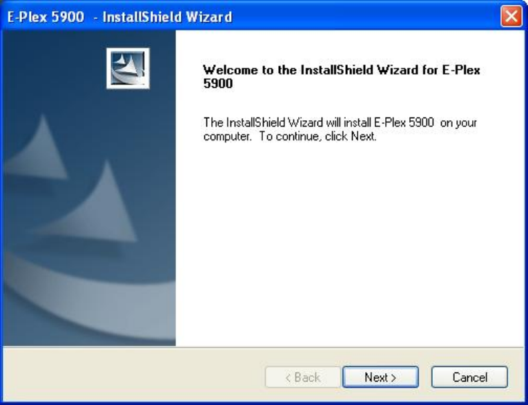
Installation
To install E-Plex 5900 M-Unit, insert the installation CD and wait for the installation application to automatically
begin. If this feature is disabled in the PC, explore the CD and click on "autorun.exe". The following screen will be
displayed:
Click on "Next" to continue.
28/37
28
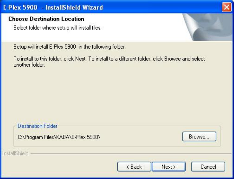
Accept the default destination folder to install the PC portion of the E-Plex 5900 M-Unit software, or click on
“Browse” and select your desired folder.
29/37
29
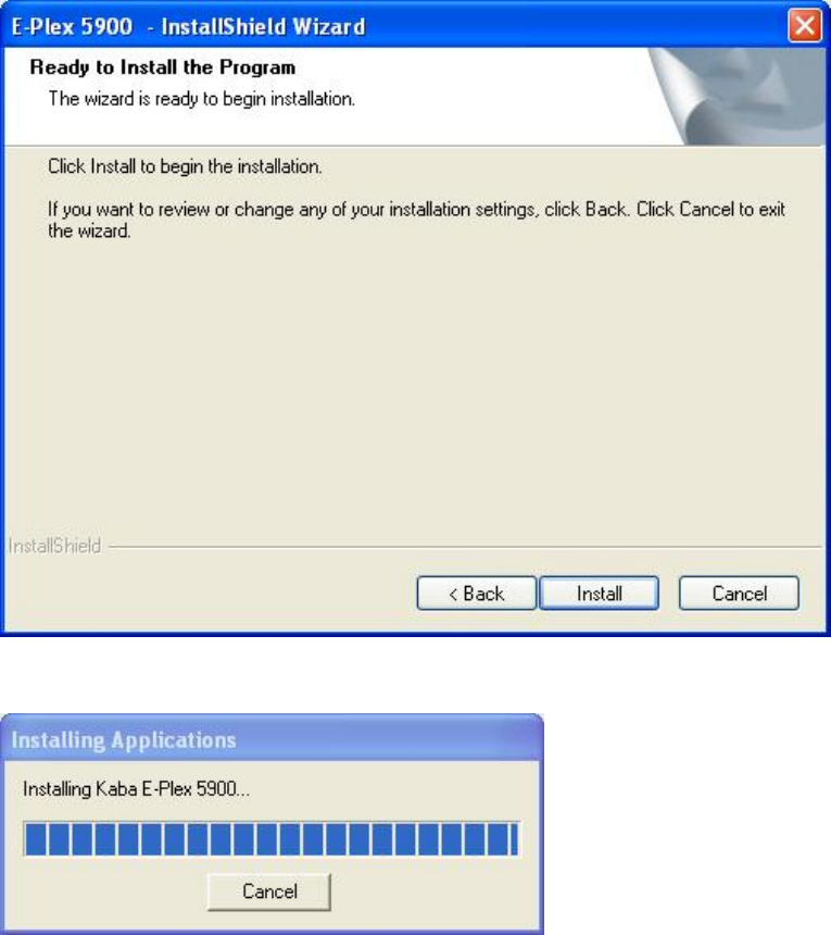
Click on "Next" to continue.
Click on "Install". You will see the following screen messages:
30/37
30
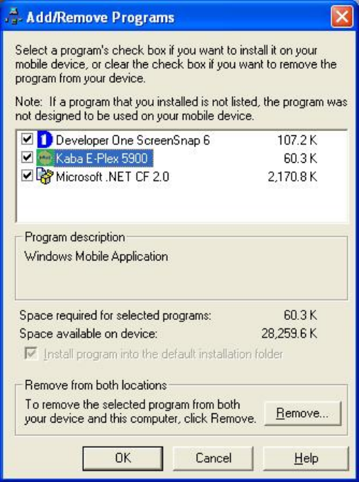
When the following screen is displayed, you will see a list of all available programs to be installed on your
Windows Mobile device. The list includes "Kaba E-Plex 5900" and "Microsoft .NET CF 2.0", which you must install,
and any other applications that need to be installed on the WM device. It is important to ensure that all items are
checked, as unchecked applications will be removed during the installation process.
31/37
31
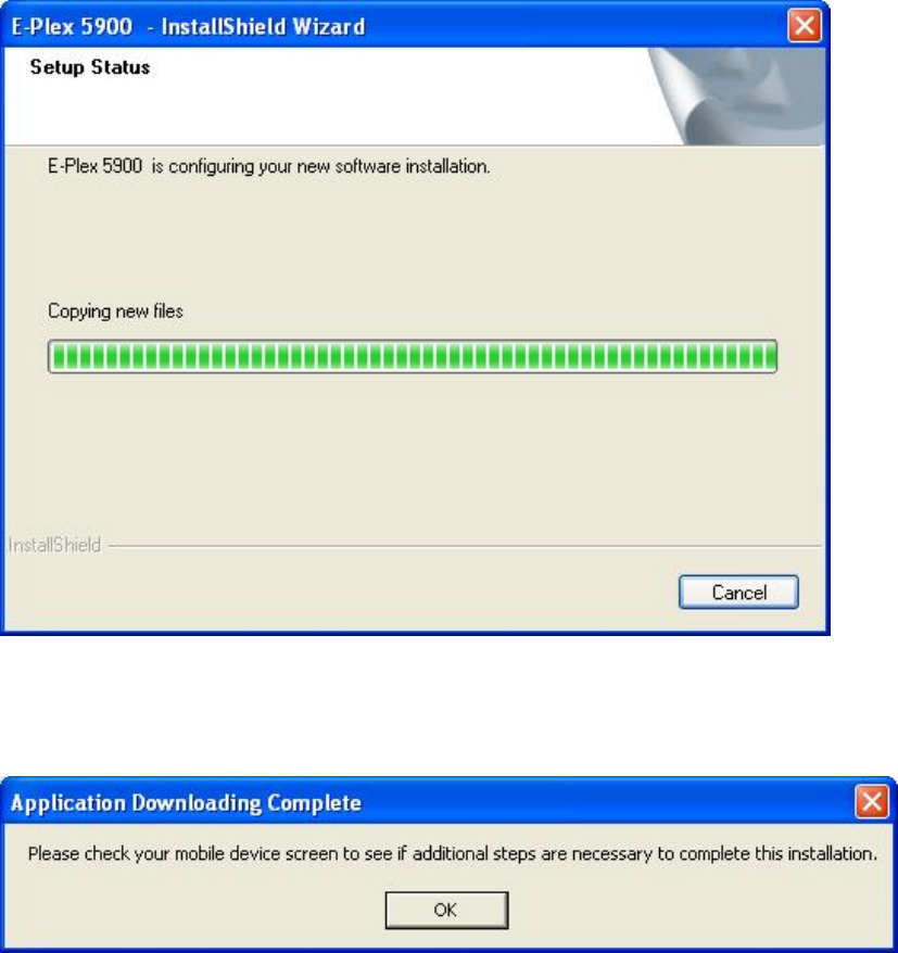
Click on "OK" to start the actual installation process as shown in the following screen:
Finally, the following prompt will be displayed:
32/37
32
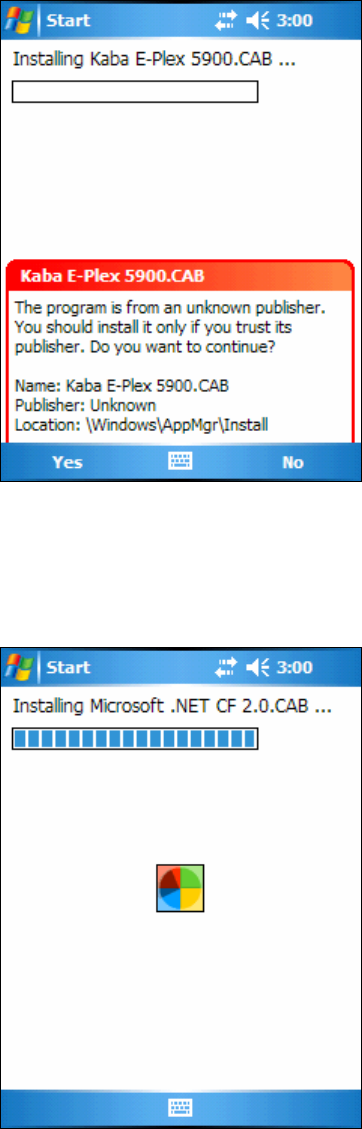
Click on "OK" and view the display on your Mobile device. You may see the following prompt:
If this prompt is displayed, select "Yes". You will then see the following screen as the E-Plex 5900 M-Unit
software (including Microsoft .NET Compact Framework) is being installed on your PPC:
33/37
33
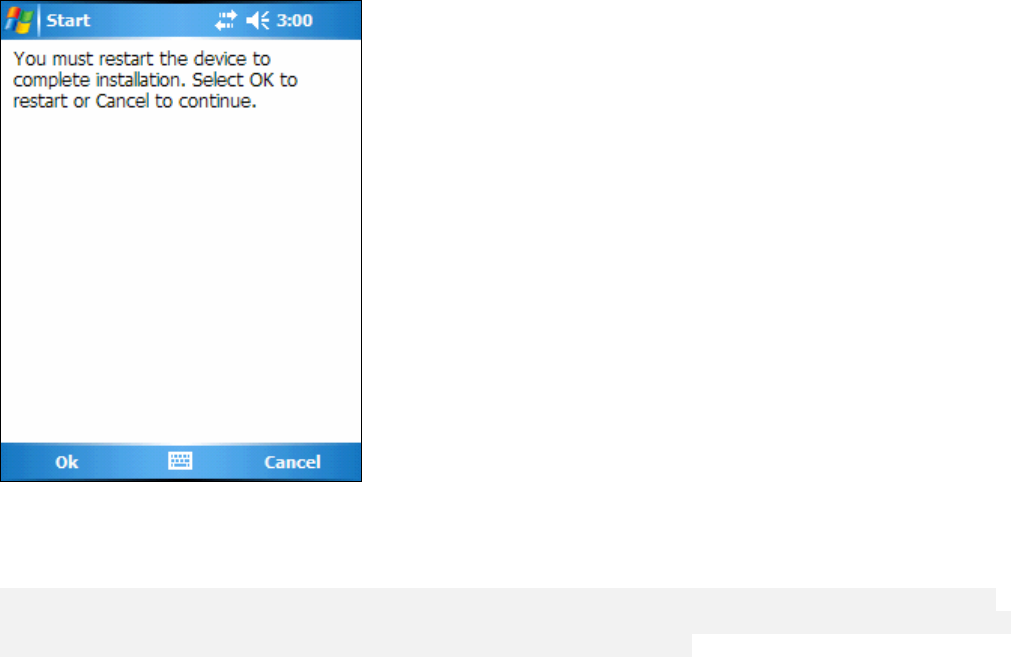
On successful completion of the installation, the following alert will be displayed:
Click "OK" to restart the WM device. The “E-Plex 5900 M-Unit” application is now installed on your PPC and is
ready to use.
To run the E-Plex 5900 M-Unit program on the PPC, click on “Start”, then “Programs” and select and click on the
application icon “EPlex5900”. For how to use this program features, please refer to Section “14. Maintenance Unit
(M-Unit PDA)” on page 14 of the E-Plex 5900 Card Connect Lock User Guide.

34/37
34
17.2.1 Uninstalling E-Plex 5900 M-Unit Application
To remove the application, use the PC function Add or Remove Programs, found in the Control Panel of your PC.
E-Plex 5900 M-Unit will not uninstall completely if you attempt to remove it via the ActiveSync interface.
Ensure that your WM device is connected to your PC and is turned on.
From the PC Control Panel, open the Add / Remove Programs page, and select E-Plex 5900 M-Unit. Click the
"Change/Remove" button. You will see a "Preparing to Install" message, followed by the following prompt:
35/37
35
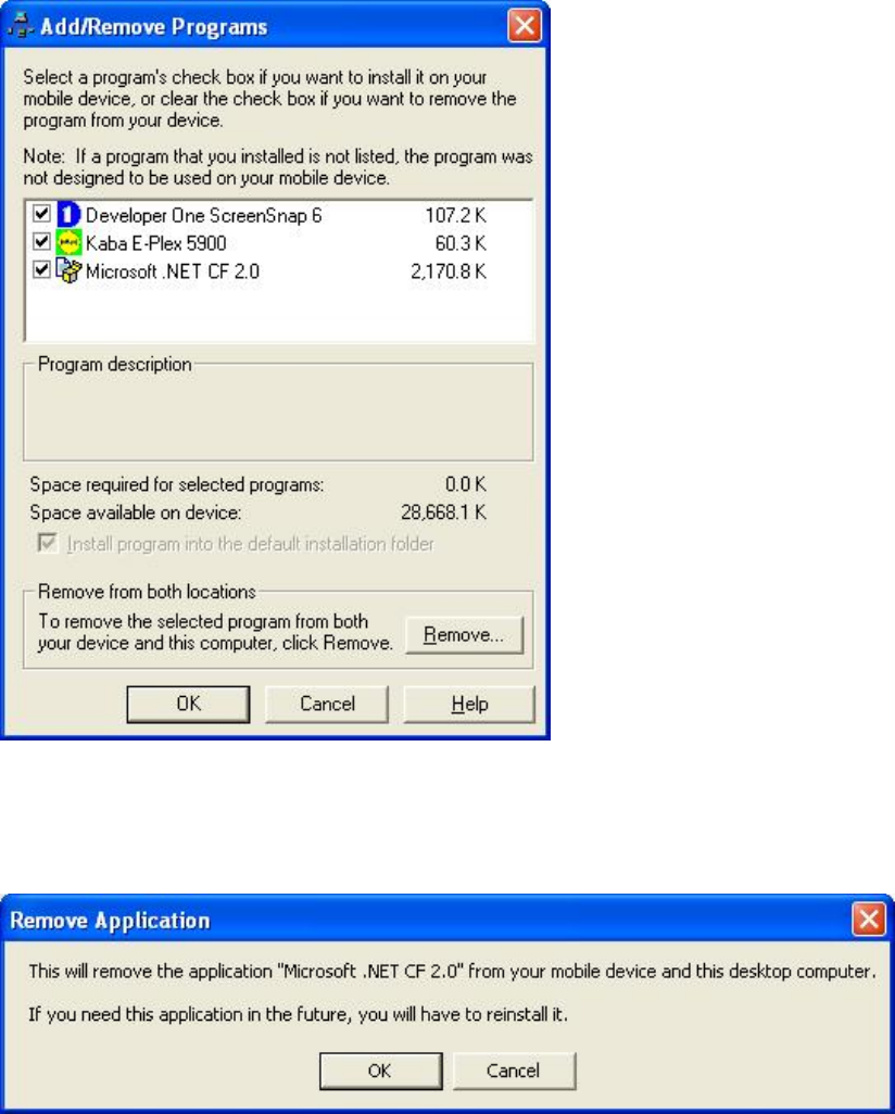
Click "Yes" and you will a screen display as shown below. The list of programs that you see near the top will
depend on what you have installed in your Windows Mobile device. Note that checked items will not be
uninstalled. Uncheck "Kaba E-Plex 5900" and "Microsoft .NET CF 2.0" in order to completely uninstall the E-Plex
5900 M-Unit application. Click on the "Remove" button to ensure that the application is removed from both your PC
and Windows Mobile device.
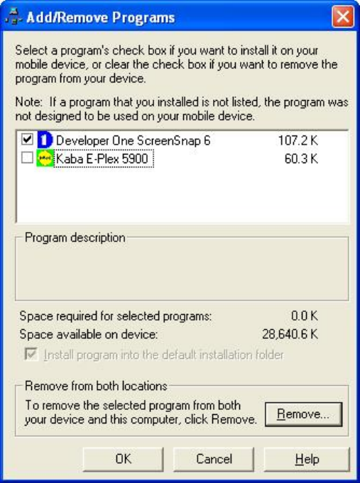
Once you have clicked "Remove", click "OK" to continue. You will see the following prompt:
36/37
36
"Click "OK" to continue. You will again see the following screen. Ensure that "Kaba E-Plex 5900" is unchecked to
uninstall and select "OK".
37/37
37
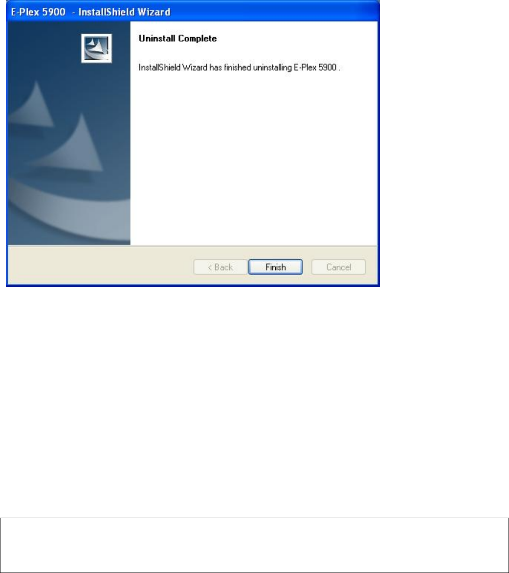
Finally, once the application is fully removed, you will see the following confirmation:
Click on “Finish” to end the uninstall operation.
Kaba Access Control Tech Support
Phone: 800-849-8324, or 336-725-1331 x400
(Monday through Friday, 8 AM to 5 PM EST)
www.kabaaccess.com