Kaba Installation Fileguard Instructions PKG3133
User Manual: Kaba Fileguard Installation Instructions - PKG3133 Simplex File Guard Cabinet Lock - Kaba Access & Data Systems
Open the PDF directly: View PDF ![]() .
.
Page Count: 12
SIMPLEX®FILE GUARD™ (FG SERIES)
INSTALLATION AND OPERATION INSTRUCTIONS
Warnings and Cautions
Kaba Access Control is not responsible for damage, injury or
malfunction due to incorrect installation.
Warning: For proper security, combination should be changed
before lock is installed on cabinet.
Caution: Wear safety glasses when preparing file cabinet.
TOOLS REQUIRED
• 1⁄8" (3 mm) Drill bit • 9⁄16" (14 mm) Wrench/Socket
• 13⁄32" (10 mm) Drill bit • Drill (variable speed is recommended)
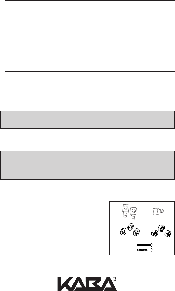
CHECKLIST
• Housing Assembly and Locking Bar
• Installation Manual
• Hardware Installation Pack
A — (2) Clevis Pins
B — ( 1 ) Notch Pin
C — (3) Lock Washers
D — (3) 9⁄16" (14 mm) Lock Nuts
E — (2) Mounting Screws
2
TABLE OF CONTENTS
Tools Required . . . . . . . . . . . . . . . . . . . . . . . . . . . . . . . . . . . . . . . . . . . . . . . . . . . . .2
Checklist . . . . . . . . . . . . . . . . . . . . . . . . . . . . . . . . . . . . . . . . . . . . . . . . . . . . . . . . . .2
A. Installation . . . . . . . . . . . . . . . . . . . . . . . . . . . . . . . . . . . . . . . . . . . . . . . . . . . . .3
B. Operation . . . . . . . . . . . . . . . . . . . . . . . . . . . . . . . . . . . . . . . . . . . . . . . . . . . . .5
C. Change the Combination . . . . . . . . . . . . . . . . . . . . . . . . . . . . . . . . . . . . . . . .5
D. Instructions for Resetting an Unknown Combination . . . . . . . . . . . . . . . .6
For technical assistance please call
1.800.849.TECH (8324) or 336.725.1331
AB
CD
E
3
c
a
b
d
e
de
f
h
g
ij
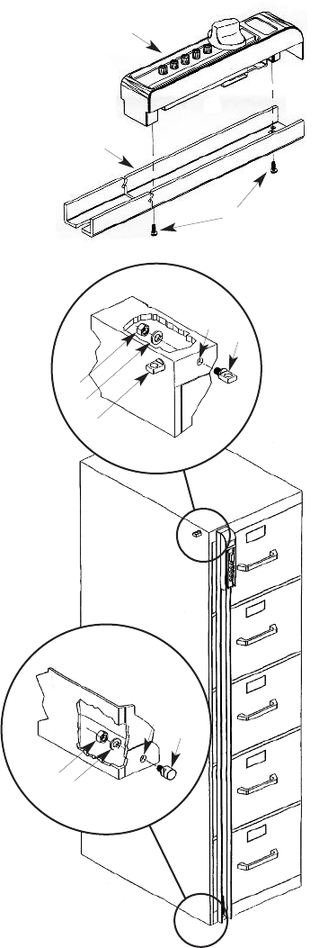
A. INSTALLATION
A-1 Preassemble File Guard housing (a) to
Locking Bar (b) by utilizing (2)
mounting screws (c).
A-2 Position the File Guard on either
side of the file cabinet.
A-3 Be sure the File Guard is parallel
to the side of the file cabinet
and that the top of the bar is
flush or slightly lower than the
top of the cabinet when marking
the Notch Pin (j) location at the
base of the cabinet. Make sure
that the Locking Bar will
engage the Notch Pin (j)
sufficiently.
A-4 The bottom of the File Guard
should extend enough to fully
engage Notch Pin (j) and clear
the floor. It may be necessary to
trim the bottom of the Locking
Bar to provide clearance with the
floor.
A-5 Mark and drill a 1⁄8" pilot hole (i).
A-6 Drill a 13⁄32" hole (i) in the base of
the file cabinet and install the
Notch Pin (j).
A-7 Mount File Guard on
Notch Pin (j), mark the
position for Clevis Pin
(h) in the upper frame
of the file cabinet.
A-8 Drill a 1⁄8" pilot hole (g).
A-9 Drill a 13⁄32" hole (g) in the
upper frame and install the
Clevis Pin.
A-10 Optional: Install the extra Clevis Pin
(f) on the side of the file cabinet to
store the File Guard when not in use.
A-11 Your File Guard is now ready to use.

4
Kaba Access Control warrants the Simplex to
be free from defects in material and workman-
ship under normal use and service for a period
of one (1) year from date of purchase. Kaba Access Control will repair
or replace, at our discretion, Simplex Locks found by Kaba Access
Control analysis to be defective during this period. Our only liability,
whether in tort or in contract, under this warranty is to repair or
replace products that are returned to Kaba Access Control within the
one (1) year warranty period.
This warranty is in lieu of and not in addition to any other warranty or
condition, express or implied, including without limitation mer-
chantability, fitness for purpose or absence of latent defects.
ATTENTION: This warranty does not cover problems arising out of
improper installation, neglect or misuse. All warranties implied or
written will be null and void if the lock is not installed properly and /or
if any supplied component part is substituted with a foreign part. If
the lock is used with a wall bumper, the warranty is null and void. If a
doorstop is required, we recommend the use of a floor secured stop.
The environment and conditions of use determine the life of finishes
on Kaba Access Control products. Finishes on Kaba Access Control
products are subject to change due to wear and environmental corro-
sion. Kaba Access Control cannot be held responsible for the deterio-
ration of finishes.
Authorization to Return Goods
Returned merchandise will not be accepted without prior approval.
Approvals and Returned Goods Authorization Numbers (RGA
Numbers) for Simplex are available through our Customer Service
department in Winston-Salem, NC 800.849.8324. The serial number
of a lock is required to obtain this RGA Number. The issuance of an
RGA does not imply that a credit or replacement will be issued.
The RGA number must be included on the address label when materi-
al is returned to the factory. All component parts including latches and
strikes (even if not inoperative) must be included in the package with
return. All merchandise must be returned prepaid and properly pack-
aged to the address indicated.
SIMPLEX®LIMITED WARRANTY
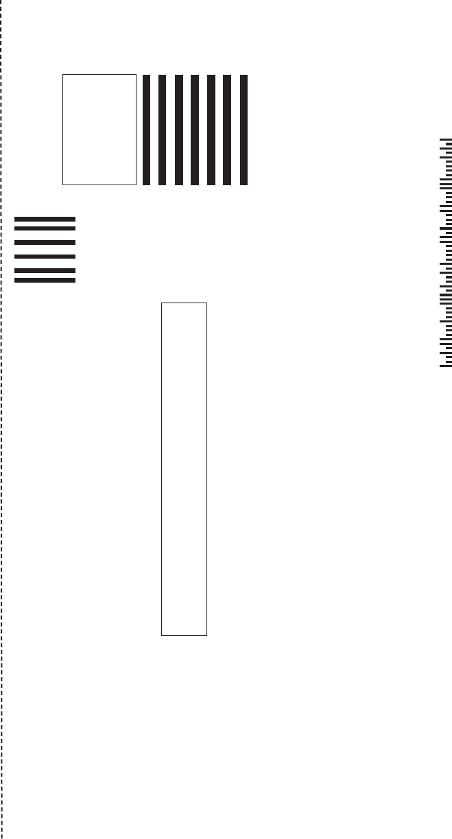
KABA ACCESS CONTROL
2941 INDIANA AVENUE
WINSTON-SALEM, NC 27199-3770
NO POSTAGE
NECESSARY
IF MAILED
IN THE
UNITED STATES
BUSINESS REPLY MAIL
FIRST-CLASS MAIL PERMIT NO. 1563
POSTAGE WILL BE PAID BY ADDRESSEE
WINSTON-SALEM, NC

Thank you for purchasing our product. In order to
protect your investment and to enable us to better
serve you in the future, please fill out this registration
card and return it to Kaba Access Control, or
register online at www.kabaaccess.com.
This lock will be used in what type of facility?
oCommercial Building oIndustrial/Manufacturing oAirport
oCollege/University oGovernment/Military oSchool/Educational
oHospital/Healthcare oOther (please specify)
What area is being secured with this lock? (e.g. Front Door, Common Door, Exercise Room)
This lock is:
oNew Installation
oReplacing a conventional keyed lock
oReplacing a Kaba Mechanical Pushbutton Lock
oReplacing a Kaba Electronic Access Control
oReplacing a Keyless Lock other than Kaba
How did you learn about Kaba Access Control Pushbutton Locks?
oAdvertisement o Previous Use oInternet/Web oAnother Use
oLocksmith oMaintenance oTraining Class oOther (please specify)
What was your reason for buying this lock?
Who installed your lock?
oLocksmith oMaintenance oOther
oCheck here if you would like more information on Kaba Access Control locks.
Name
Position
Company
Address
City
State ZIP (Postal Code) Country
Phone
Email
Name of Dealer Purchased From
Date of Purchase
Lock Model Number
REGISTRATION CARD
5
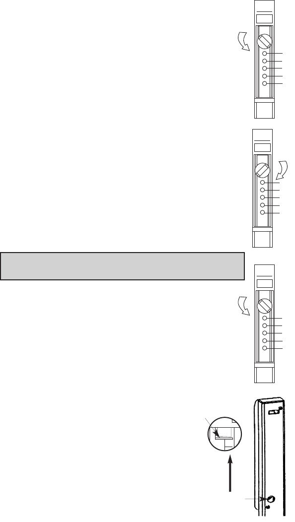
B. OPERATION
All file guard locks are shipped with a preset factory
combination: 1, 2, 3
B-1 Turn control knob LEFT (counterclockwise) to stop
position, and release to clear chamber.
B-2 Press the CORRECT buttons in the PROPER order
in your current combination. Release buttons after
pressing each number in the combination. (For new
units, current (factory) code is 1, 2, 3)
B-3 Turn control knob RIGHT (clockwise), to stop position.
The bolt should now be retracted.
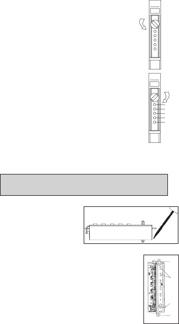
C. CHANGING THE COMBINATION
Note: Combination should be changed before lock is
installed onto cabinet.
Select the number of buttons and the desired sequence
(order) in which the buttons will be in your combination.
Each number can only be used once. Two or more num-
bers can be set at one time, developing a different com-
bination than if pushed individually.
C-1 Turn control knob LEFT (counterclockwise), to stop
position, and release to clear chamber. Enter current
combination by pressing the
correct buttons in proper order.
(For new units, current (factory)
code is 1, 2, 3)
C-2 Through the round opening on
the back side of the File Guard
locking bar, push the combina-
tion change tab up.
1
2
3
4
5
1
2
3
4
5
1
2
3
4
5
Combination change
tab access opening.
PUSH
Combination
change tab
6
C-3 Turn control knob Left (counterclockwise), to stop
position and release to clear the existing lock
combination.
C-4 Press buttons in proper order for NEW combination.
Press the buttons firmly to insure activation.
Record your new combination.
C-5 Turn control knob Right (clockwise) 90º, to stop
position, to set the NEW combination.
Note: If the lock opens without a combination being
entered, the lock is in “0” code. A step was omitted
during the process. Repeat Steps C-2 thru C-5.
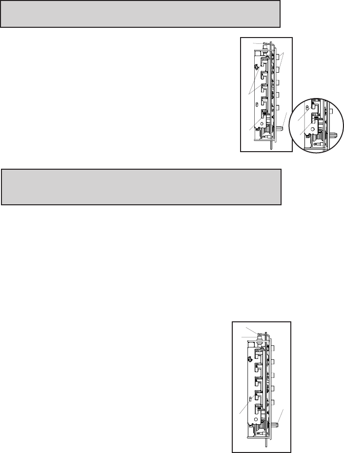
D. INSTRUCTIONS FOR RESETTING AN
UNKNOWN COMBINATION
Remove the push button unit from the file guard bar by removing
the 2 screws on the back of the file guard bar. Set the bar aside.
Remove the combination chamber from the lock held in by 2 screws.
To remove the 3-sided dust cover marked “Kaba Simplex,” place
the combination chamber in the
position below.
D-1 Place a small screwdriver on
the edge of the 3-sided dust
cover and push down on the
screwdriver. The cover should
pop loose. Once it does, pull the cover off of the
combination chamber.
D-2 Hold the chamber in one hand by the screw tabs (b)
on each end with the key-stems (c) facing you and the
control shaft (d) at the bottom.
D-3 Using pliers or equivalent, rotate the control shaft (d)
counterclockwise and release to clear thechamber.
b
b
d
1
2
3
4
5
c(5)
(3 sided dust cover)
7
D-4 Look at the 5 code gears (e). If any code gear pockets (f) are
already at the shear line (open position), ignore them. They are
not used in the combination.
Note: Shear line (open position) references the “L” shaped feet
already align with the mating gear pocket.
D-5 Find the code gear pocket/s (e) that is farthest away
from the shear line (open position). Depress that key-
stem/s (c) and release. If any digits in the combination
were depressed together (at the same time), then they
must also be depressed together to reset the combina-
tion.
D-6 Find the code gear pocket/s (e) that is the next
farthest away from the shear line (open position).
Depress that key-stem/s (c) and release.
Note: If any of the code gear pockets travel past the shear line
(open position), the key stems have been depressed in the wrong
sequence. Start over at D-3.
D-7 Repeat step D-6 until all code gear pockets (e) are at the shear
line (open position).
D-8 If all the code gear pockets (e) are not lined up at the shear line
(open position), start over at step D-3.
D-9 Depress the lockout slide (g) at the top of the chamber and
release. (looks like one end of a spark plug)
D-10 Using pliers or equivalent, rotate the control shaft (d) counter-
clockwise to clear the chamber and release. The
lockout slide (g) should pop out (button underneath
will stay depressed bh8).
D-11 Depress the key-stem/s (c) that you want in the
new combination, releasing each after it is
depressed.
D-12 Once all the digits in the new combination have
been depressed, with pliers or equivalent, rotate
the control shaft (d) clockwise. The code change
button (h) underneath the lockout slide (g), should
pop up. The new combination is now set.
h
g
f
d
f
g
c (5)
e (5)
d
e
f
8
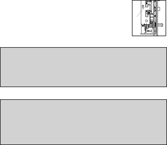
D-13 Look at the code gear pockets (e). The digits in
the new combination should not be at the shear
line (open position).
Reinstallation:
Replace the 3-sided dust cover marked “Kaba Simplex.” Make sure
the staked joints on both end plates fit through the slots on the dust
cover. Stake the 2 end plate joints. Replace the combination chamber
into the lock. Remount the lock housing assembly to locking bar.
Testing:
Enter the combination set during the reset process. Turn the
thumbturn to the right (clockwise). The bolt should retract. If not,
turn the thumbturn left (counterclockwise) and release. Enter the
combination again and turn thumbturn to the right (clockwise). If
still unsuccessful, start over at D-1.
e

9
Notes

Kaba Access Control
2941 Indiana Avenue
Winston-Salem, NC 27105 USA
Tel: 800.849.8324 or 336.725.1331
Fax: 800.346.9640 or 336.725.3269
www.kabaaccess.com PKG3133 0609
