Kaba Installation Instructions Simplex 3000 PKG2586
User Manual: Kaba Simplex 3000 Installation Instructions - PKG2586 Simplex 3000 Mechanical Lock - Kaba Access & Data Systems
Open the PDF directly: View PDF ![]() .
.
Page Count: 16
Installation Instructions
SIMPLEX®3000 NARROW STILE
2
TABLE OF CONTENTS
Package Contents . . . . . . . . . . . . . . . . . . . . . . . . . . . . . . . . . . . . . . . . . . . . . . . . . . . . .2
Tools Required . . . . . . . . . . . . . . . . . . . . . . . . . . . . . . . . . . . . . . . . . . . . . . . . . . . . . . . .2
A. Combination Lock Assembly . . . . . . . . . . . . . . . . . . . . . . . . . . . . . . . . . . . . . . . .3
B. Mounting Lock to Stile . . . . . . . . . . . . . . . . . . . . . . . . . . . . . . . . . . . . . . . . . . . . . .4
C. Operating Instructions . . . . . . . . . . . . . . . . . . . . . . . . . . . . . . . . . . . . . . . . . . . . . .6
Warranty . . . . . . . . . . . . . . . . . . . . . . . . . . . . . . . . . . . . . . . . . . . . . . . . . . . . . . . . . . . . .8
D. Combination Change Information . . . . . . . . . . . . . . . . . . . . . . . . . . . . . . . . . . . .9
E. Resetting an Unknown Combination . . . . . . . . . . . . . . . . . . . . . . . . . . . . . . . . . .11
Warnings and Cautions
Important: Carefully inspect windows, doorframe, door, etc. to ensure that
the recommended procedures will not cause any damage. Kaba Access
Control’s warranty does not cover damages caused by installation.
Caution: Wear safety glasses when preparing door.
• Combination lock assembly
• Instructions for changing
combination
• Operating instructions
• Warranty card
• DF-59 keys
• Mounting screws 10-24 thd. X 2 1⁄8"
• Inside trim plate assembly
• Cylinder groove screws #4
self-tapping screw
• Optional cylinder guard (3002
models only)
• Cam stop screw 6–32 thd. X 3⁄16"
long
PACKAGE CONTENTS
TOOLS REQUIRED FOR INSTALLATION:
• Flat blade screwdrivers (small and medium)
• Phillips head screwdriver (large)
• Tape
• Hammer
• Deburring tool
• Drill (variable speed recommended)
• Center punch
• (3⁄32") drill bit
• (3⁄8") drill bit
• (1⁄8") drill bit
• (1⁄4") drill bit
• (7⁄8") hole saw
3
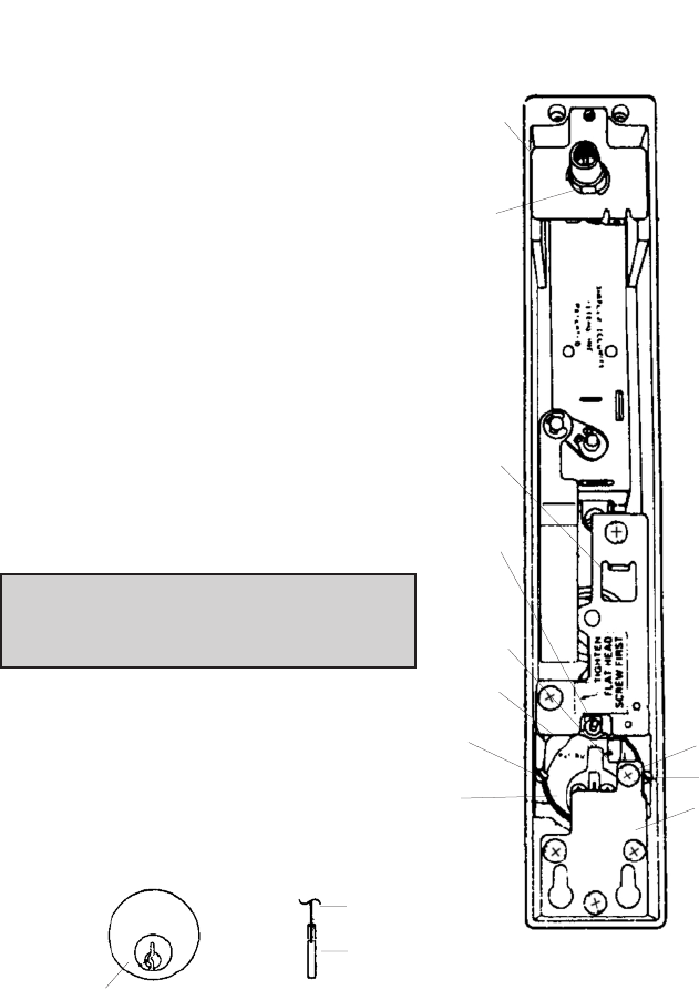
A. COMBINATION LOCK ASSEMBLY
A-1 Cylinder Installation: Remove interposer
assembly (A) by removing one round head
screw and one flat head screw (See Figure 1-1).
A-2 Install Mortise cylinder by turning
cylinder until cylinder cam (E)
contacts lock-in plate (B) (See
Figure 1-1). Turn cylinder to the
left (counterclockwise) less than
one turn until the key is positioned
in pull position (See Figure 1-2), also aligning
to cylinder set screw grooves (See Figure 1-1).
A-3 Assemble two cylinder positioning screws (C).
Make sure the heads of these screws are below
the underside of the cylinder cam (See Figure
1-1).
A-4 Reassemble the interposer assembly (A).
Interposer arm should be positioned central to
the cylinder cam (See Figure 1-3).
A-5 Assemble cam stop screw (D).
Note: Interposer stud to be centered before
mounting combination lock assembly
(See Figure 1-1).
A
Detent Position
of Interposer
Mortise
Cylinder
Code Plate and
Stud Assembly
Combination
Change Sleeve
Interposer
Stud
E
Cylinder in
“Pull” Position
Figure 1-3
Figure 1-2
Figure 1-1
Interposer
Arm
Cylinder
Cam
CD
B
Partial Rear View
of Narrow Stile Lock
Assembly
Side View
C
4
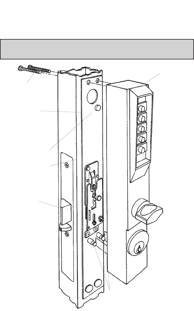
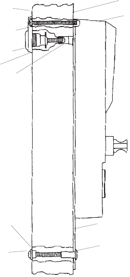
B. MOUNTING LOCK TO STILE
B-1 Place combination lock assembly over lock-in studs and slide downward
until a stop position is attained (approximately 1⁄8" of movement) (See
Figure 2-1). The top of the lock housing and drive assembly should be
flush when properly positioned.
Note: Before closing door, refer to operating instructions to check out the
operation of all lock functions.
Combination
Lock Assembly
A
As shown on Each
Drive Assembly
• 31⁄32" B.S. - L.H. Drive
• 31⁄32" B.S. - R.H. Drive
• 11⁄8" B.S. - L.H. Drive
• 11⁄8" B.S. - R.H. Drive
Housing Locator Stud
Drive Assembly
(Sample Illustration)
Latch Direction Will
Vary Based on Swing of
Door (Illustration Shows
Outswing Door)
Lock-In Studs
Figure 2-1
5
B-2 Fix two each 10-24 x 2 1⁄8" long round head machine screws (A) as shown
(See Figures 2-1 & 2-2). Using the DF-59 key, thread the control lock
assembly (B) into the combination change sleeve (C) DF-59 (See Figure
2-2) until trim plate is snug against stile. The key can only be removed in
vertical position.
Narrow Stile Combination
Lock Side
Narrow Stile
Trim Plate Side Combination Lock
Assembly Side View
Drive Assembly
Threaded Sex Bolts
Narrow Stile Door Edge View
B
Trim Plate
C
Mounting Bushing
Mounting Screws
A
Figure 2-2
6
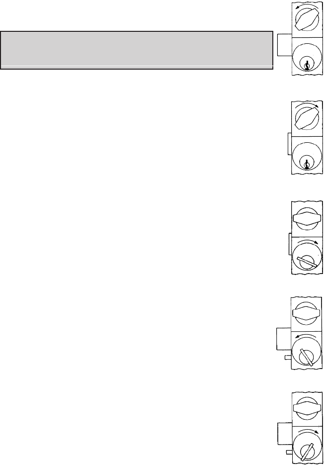
C. OPERATING INSTRUCTIONS
Note: All locks are shipped with the following combination:
#2 and #4 pushed at the same time, then #3. For proper security,
the factory set code must be changed at the time of installation.
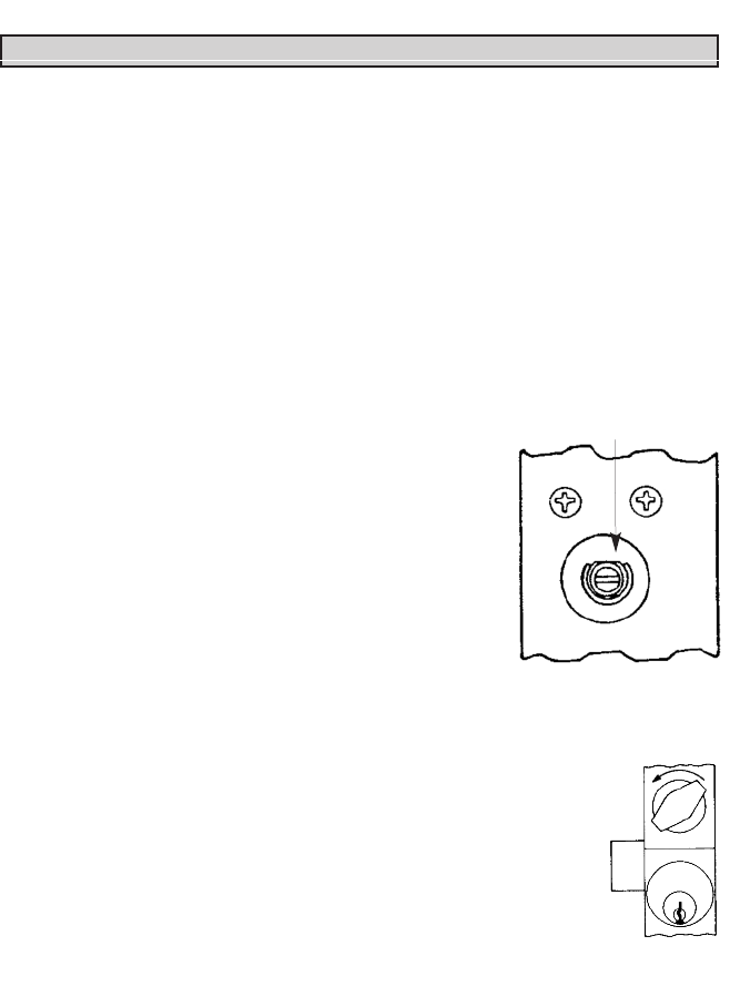
C-1 Gaining Access By Combination Code
A. To clear any previously depressed code buttons, turn the thumb
turn to the left (counterclockwise) and release (See Figure 3-1).
B. Depress the code buttons in the proper order of your
combination. Release buttons after depressing.
C. Turn the thumb turn clockwise to the stop position. Observe the
latch being retracted to unlock the door (See Figure 3-2). The
lock will lock automatically when the thumb turn is released.
C-2 Gaining Access By Key Override
Insert cylinder key into cylinder on combination lock side of
door. Turn the key in clockwise direction (approximately 90°)
(See Figure 3-3). The latch should retract. Turn the key back to
key pull position and remove.
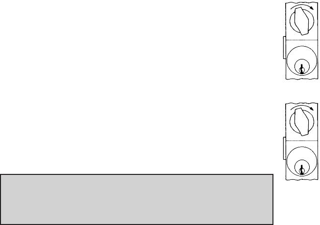
C-3 Locking Out Combination Code Access
A. Insert cylinder key into cylinder on combination lock side
of the door. Turn key in a counterclockwise direction to the
stop position (See Figure 3-4). Return the key to the pull
position and remove. The thumb turn should not turn while
the lock is in this mode.
B. To allow access again through a combination code, insert
key, turn clockwise approximately 45°. Return the key to
the pull position and remove (See Figure 3-5).
Figure 3-3
Figure 3-4
Figure 3-5
Figure 3-1
Figure 3-2
7
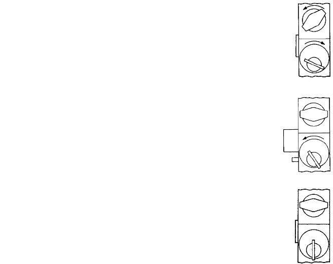
C-4 Latch Holdback
A. Insert cylinder key into cylinder on combination lock side of
the door. Turn the key in a clockwise direction to the stop
position, retracting the latch fully (See Figure 3-6). Hold the
key in that position and turn the thumb turn to the left
(counterclockwise). Bring the key to the pull position and
remove.
B. To allow the latch to return to lock mode, reinsert and turn
the key to the left (counterclockwise) to the stop position
(See Figure 3-7). Return the key to the pull position and
remove (See Figure 3-8).
Figure 3-6
Figure 3-7
Figure 3-8

8
Kaba Access Control warrants this product to be free from defects in
material and workmanship under normal use and service for a period of
one (1) year. Kaba Access Control will repair or replace, at our discre-
tion, Simplex Locks found by Kaba Access Control analysis to be defec-
tive during this period. Our only liability, whether in tort or in contract,
under this warranty is to repair or replace products that are returned to
Kaba Access Control within the one (1) year warranty period.
This warranty is in lieu of and not in addition to any other warranty or
condition, express or implied, including without limitation merchantabil-
ity, fitness for purpose or absence of latent defects.
ATTENTION: This warranty does not cover problems arising out of
improper installation, neglect or misuse. All warranties implied or writ-
ten will be null and void if the lock is not installed properly and /or if
any supplied component part is substituted with a foreign part. If the
lock is used with a wall bumper, the warranty is null and void. If a
doorstop is required, we recommend the use of a floor secured stop.
The environment and conditions of use determine the life of finishes
on Kaba Access Control products. Finishes on Kaba Access Control
products are subject to change due to wear and environmental
corrosion. Kaba Access Control cannot be held responsible for the
deterioration of finishes.
Authorization to Return Goods
Returned merchandise will not be accepted without prior approval.
Approvals and Returned Goods Authorization Numbers (RGA Numbers)
for the Simplex 3000 Series are available through our Customer
Service department in Winston-Salem, NC 800.849.8324 The serial
number of a lock is required to obtain this RGA Number. The
issuance of an RGA does not imply that a credit or replacement will be
issued.
The RGA number must be included on the address label when material
is returned to the factory. All component parts including latches and
strikes (even if not inoperative) must be included in the package with
return. All merchandise must be returned prepaid and properly pack-
aged to the address indicated.
KABA SIMPLEX®
LIMITED WARRANTY
KABA ACCESS CONTROL
2941 INDIANA AVENUE
WINSTON-SALEM, NC 27199-3770
NO POSTAGE
NECESSARY
IF MAILED
IN THE
UNITED STATES
BUSINESS REPLY MAIL
FIRST-CLASS MAIL PERMIT NO. 1563
POSTAGE WILL BE PAID BY ADDRESSEE
WINSTON-SALEM, NC

Thank you for purchasing our product. In order to
protect your investment and to enable us to better
serve you in the future, please fill out this registration
card and return it to Kaba Access Control, or
register online at www.kabaaccess.com.
This lock will be used in what type of facility?
oCommercial Building oIndustrial/Manufacturing oAirport
oCollege/University oGovernment/Military oSchool/Educational
oHospital/Healthcare oOther (please specify)
What area is being secured with this lock? (e.g. Front Door, Common Door, Exercise Room)
This lock is:
oNew Installation
oReplacing a conventional keyed lock
oReplacing a Kaba Mechanical Pushbutton Lock
oReplacing a Kaba Electronic Access Control
oReplacing a Keyless Lock other than Kaba
How did you learn about Kaba Access Control Pushbutton Locks?
oAdvertisement o Previous Use oInternet/Web oAnother Use
oLocksmith oMaintenance oTraining Class oOther (please specify)
What was your reason for buying this lock?
Who installed your lock?
oLocksmith oMaintenance oOther
oCheck here if you would like more information on Kaba Access Control locks.
Name
Position
Company
Address
City
State ZIP (Postal Code) Country
Phone
Email
Name of Dealer Purchased From
Date of Purchase
Lock Model Number
REGISTRATION CARD
9
D. COMBINATION CHANGE INFORMATION
Important: Read all instructions before beginning.
D-1 Changing Combinations: In order to change an existing combination, you
must:
1. Have a DF 59 Key
2. Know the existing combination
3. Have lock set for pushbutton access to retract latch
4. Have a small flat 1⁄8" blade screwdriver
5. Keep the door open during combination change procedure
D-2 Any or all buttons in any order, separately and/or
pushed at the same time can be used in your new
combination. Each button can only be used once
in the combination.
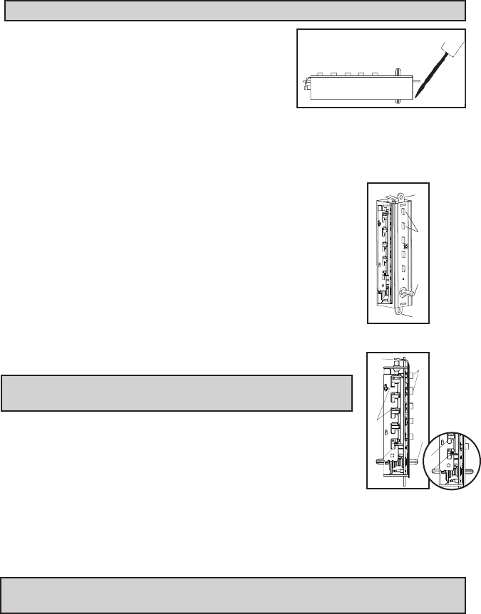
D-3 Remove the control lock assembly and trim plate
using the DF 59 key provided, exposing combination
change sleeve as shown (See Figure 4-1). Key must
be turned to the left (counterclockwise rotation
until control lock assembly can be removed from
lock).
D-4 Turn outside thumb turn counterclockwise (to the
left) to stop position and release (See Figure 4-2).
This will clear the lock of previously depressed
buttons.
D-5 Depress the buttons in the existing combination
making certain each button is fully depressed and released.
D-6 Insert the screwdriver into combination change sleeve slot
(See Figure 4-1). Gently turn the screwdriver to the right
(clockwise) to the stop position, making sure not to force it.
A slight click should be felt/heard. Turn the screwdriver to
the left (counterclockwise) to the stop, then remove.
D-7 Clear the lock of old combination by turning the thumb turn
to the left (counterclockwise) to the stop position. Release the
knob.
D-8 Depress the buttons of desired combination carefully, making sure that a
click is felt with each button(s) that is depressed, and release.
Slot for inserting
screw driver
Partial rear view of
combination change sleeve
Figure 4-2
Figure 4-1
10
D-9 Turn the thumb turn clockwise to the stop position, assuring
the latch is retracted (See Figure 4-3). Release thumb turn.
You should not be able to turn the thumb turn unless you have
depressed the buttons of your newly entered combination. The
new combination is now programmed in the lock.
D-10 Replace control lock assembly and trim plate by inserting
threaded rod portion into the combination change sleeve and
turning to the right (clockwise) until trim plate is snug against
the stile of door. The DF 59 key can be removed from control
lock assembly in the vertical position only.
D-11 Before closing door, activate new combination and turn the
thumb turn to the right (clockwise) to ensure proper retraction of
the latch (See Figure 4-4).
Warning: If you can turn the thumb turn to the right (clockwise)
without pressing any combination, you are in a “0” combination
because some steps above were performed out of order. To reset
a combination, follow the above steps, but omit D-5.
Figure 4-3
Figure 4-4
11
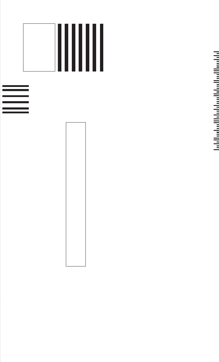
E. RESETTING AN UNKNOWN COMBINATION
Remove the combination chamber, held by 2 screws, from the lock.
To remove the 3-sided dust cover marked
"Kaba,” “Simplex," etc. place the combination
chamber in the position to the right.
E-1 Place a small screwdriver on the edge of the
3-sided dust cover and push down on the
screwdriver (See Figure 5-1). The cover
should pop loose. Once it does, pull the
cover off of the combination chamber.
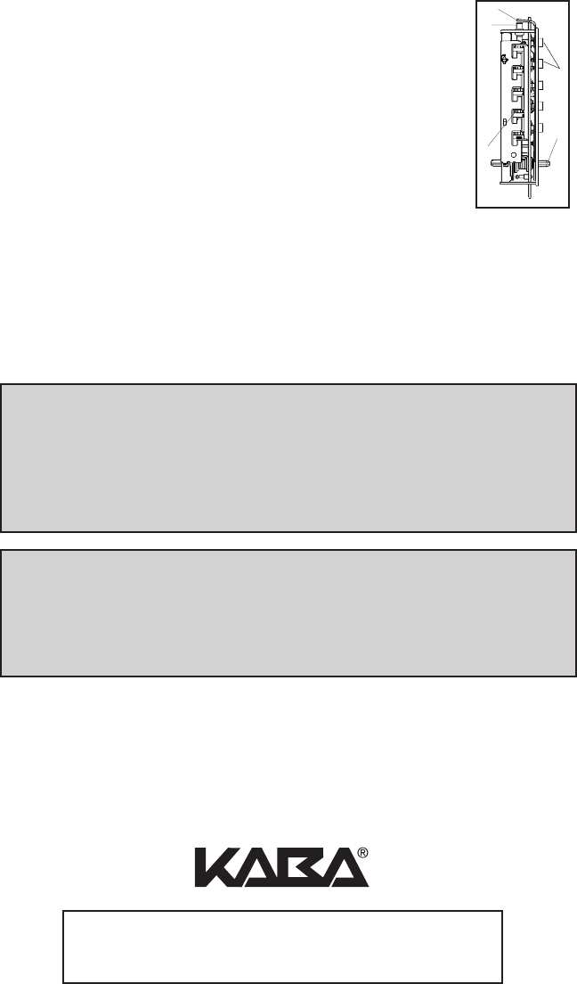
E-2 Hold the chamber in one hand by the screw
tab (b) on each end with the key-stems (c)
facing you and the control shaft (d) at the
bottom (See Figure 5-2).
E-3 Using pliers or equivalent, rotate the control shaft (d)
counterclockwise and release to clear the chamber
(See Figure 5-2).
E-4 Look at the 5 code gears (e). If any code gear pockets
(f) are already at the shear line (open position), ignore
them. They are not used in the combination
(See Figure 5-3).
Note: Shear line (open position) references the “L” shaped
feet already align with the mating gear pocket.
E-5 Find the code gear pocket/s (e) that is farthest away
from the shear line (open position). Depress that key-
stem/s (c) and release (See Figure 5-3). If any digits in
the combination were depressed together (at the same
time), then they must also be depressed together to
reset the combination.
E-6 Find the code gear pocket/s (e) that is the next farthest away from the
shear line (open position). Depress that key-stem/s (c) and release (See
Figure 5-3).
Note: If any of the code gear pockets travel past the shear line, the key stems
have been depressed in the wrong sequence. Start over at E-3.
E-7 Repeat step E-6 until all code gear pockets (e) are at the shear line
(open position).
E-8 If all the code gear pockets (e) are not lined up at the shear line
(open position), start over at step E-3.
(3 sided dust cover)
Figure 5-1
Figure 5-2
Figure 5-3
f
gc(5)
e(5)
d
b
d
b
c(5)
f
e
12
For technical assistance please call
1.800.849.TECH (8324) or 336.725.1331
E-9 Depress the lockout slide (g) at the top of the chamber
and release. (looks like one end of a spark plug)
(See Figure 5-4).
E-10 Using pliers or equivalent, rotate the control shaft (d)
counterclockwise to clear the chamber and release. The
lockout slide (g) should pop out (button will stay
depressed) (See Figure 5-4).
E-11 Depress the key-stem/s (c) that you want in the new
combination, releasing each after it is depressed
(See Figure 5-2).
E-12 Once all the digits in the new combination have been depressed, with
pliers or equivalent, rotate the control shaft (d) clockwise (See Figure
5-4). The code change button (h) underneath the lockout slide (g),
should pop up (See Figure 5-4). The new combination is now set.
E-13 Look at the code gear pockets (e). The digits in the new combination
should not be at the shear line (open position) (See Figure 5-3).
Reinstallation: Replace the 3-sided dust cover marked “Kaba,” “Simplex,” etc.
Make sure the staked joints on both end plates fit through the slots on the
dust cover. Stake the 2 end plate joints. Replace the combination chamber
into the lock using the same 2 screws removed earlier. Replace any other
components removed earlier during this process. Reinstall the lock assembly
to the door.
Testing: Enter the combination set during the reset process. Turn the outside
thumbturn to the right (clockwise). The latch should retract. If the latch does
not retract, turn the outside thumbturn left (counterclockwise) and release.
Enter the combination again, and turn the thumbturn to the right (clockwise).
If still unsuccessful, start over at step E-1.
Figure 5-4
h
g
e
d
c(5)

13
Notes

Kaba Access Control
2941 Indiana Avenue
Winston-Salem, NC 27105 USA
Tel: 800.849.8324 or 336.725.1331
Fax: 800.346.9640 or 336.725.3269
www.kabaaccess.com PKG2586 0709
