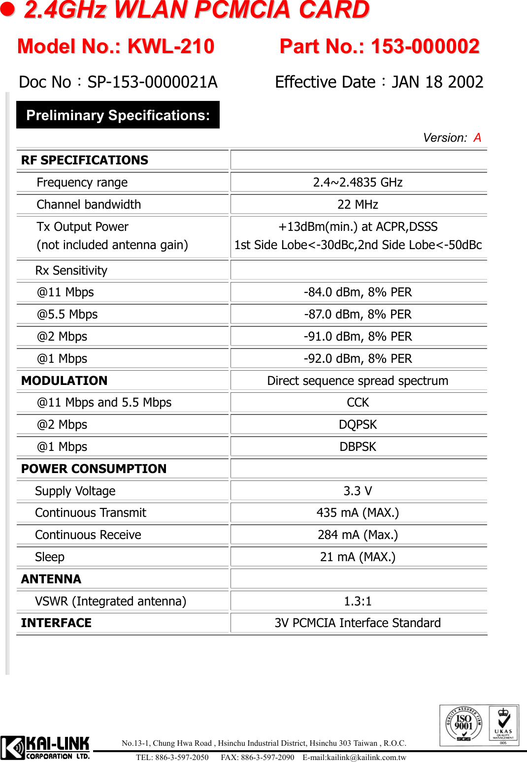
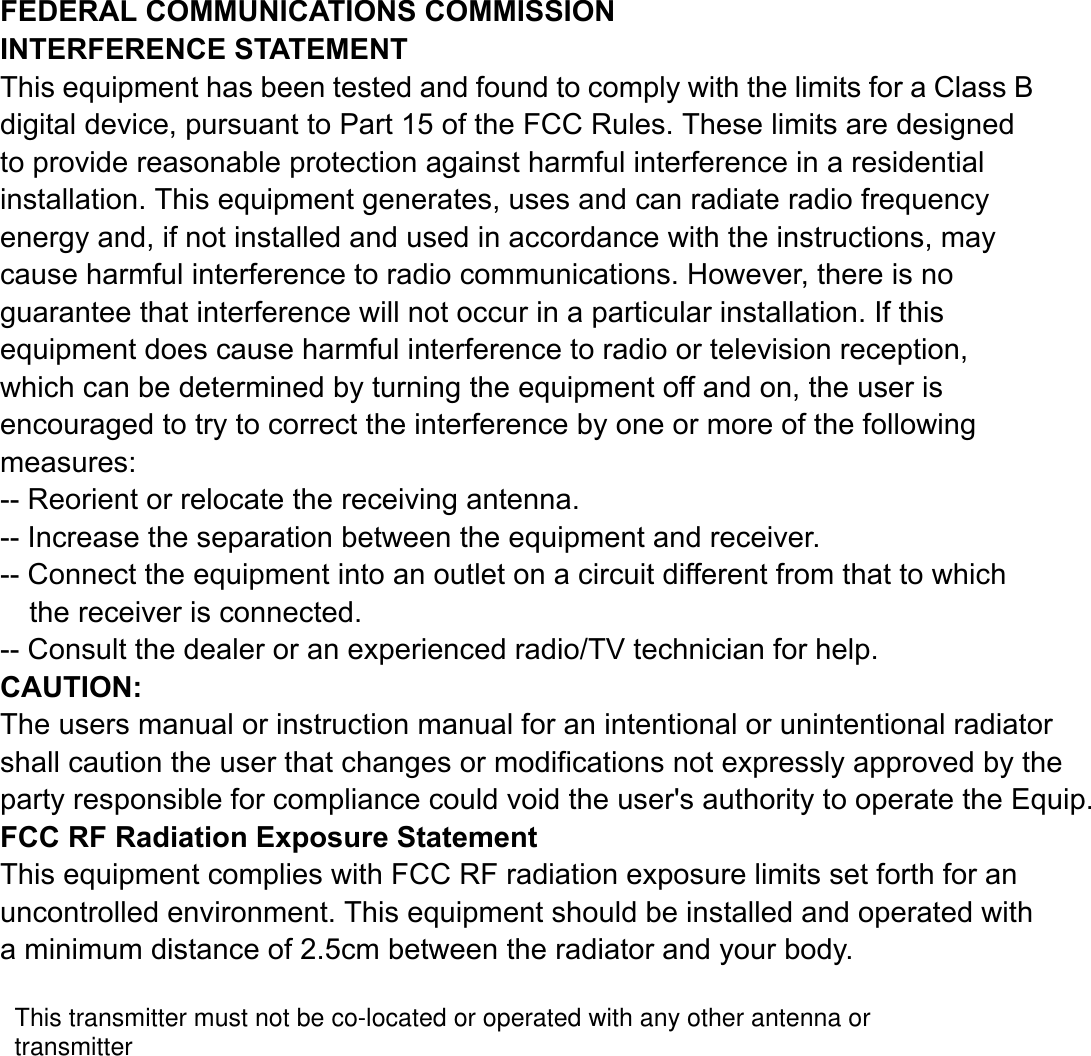
Kai Link KWL-210 WLAN PCMCIA Card User Manual manual201

Kai-Link Corporation Ltd. WLAN PCMCIA Card manual201

Revised Manual

       KAI-LINK Wireless LAN    KWL-210(PCMCIA card) KWL-220(USB adapter)         User’s Guide
 Page 1 Contents  1 Introduction .......................................................................................2 1.1 Package Contents ........................................................................................................ 3 1.2 System Requirements ................................................................................................. 3 1.3 Firmware Features...................................................................................................... 3 1.4 Driver Features ........................................................................................................... 4 2 Quick Installation..............................................................................5 3 Installation Procedures Under Windows/95/98/Me/2000 ...............7 3.1 Installing the Application and Drivers Under Windows 95/98/2000...................... 7 3.2 Uninstall Procedure Under Windows 95/98/Me..................................................... 14 3.3 Uninstall Procedure Under Windows 2000............................................................. 14 4 Installation Procedures Under Windows NT 4.0 ..........................16 4.1 Installing the Driver Under Windows NT 4.0 ........................................................ 16 4.2 Configuration Under Windows NT 4.0 ................................................................... 17 4.3 Uninstall Procedure Under Windows NT 4.0 ......................................................... 17 5 Configuration & Monitor Utility......................................................19 5.1 How to Install the Configuration & Monitor Utility ............................................. 19 5.2 Using the Configuration & Monitor Utility............................................................ 20 5.3 How to Uninstall the Configuration & Monitor Utility......................................... 27 6  Warranty & Contact US………………………………………………..28
 Page 2  1 Introduction The KAI-LINK KWL-210/220 is a Wireless LAN Card with a rate of 1, 2, 5.5, and 11 Mbps operating in the ISM band using Direct Sequence Spread Spectrum (DSSS) transmission, implementing the IEEE 802.11b standard. For these card KAI-LINK currently provides Device Drivers for   MS Windows® 95/98/2000, Windows® NT 4.0,and Windows CE.  Linux Drivers will be supported soon.    KAI-LINK also provides tools for the configuration and firmware upgrade of the cards. These tools, as well as the installation procedure for the MS Windows 95/98/2000, MS Windows® NT4.0, operating systems are described in this document.  Two pieces of software are needed, in order to install the adapter in a PCMCIA card or USB adapter slot of a PC and operate under an operating system. The first one is the driver, which provides the necessary mechanisms to the operating system in order to use the adapter as any other networking adapters. The driver communicates with the firmware using exchange of commands (Set MIB, Get MIB, Scan, Sync, etc.). The other piece of software needed is the code written on the MAC chip, which is responsible for the implementation of the IEEE 802.11b, and for the interface with driver.
 Page 3  1.1 Package Contents Before you do anything, open your package and verify it includes:    A KAI-LINK KWL-210 / 220 Wireless LAN Card     Firmware, Drivers, User Guide, and Software Tools CD  1.2 System Requirements  Operating System: MS Windows 95/98/2000, Windows NT 4.0 with Service Pack 4 or later   Desktop PC or notebook PC with CD-ROM drive   SA to PCMCIA or PCI to PCMCIA controller in case of desktop PC (For KAI-LINK KWL-210)   PCMCIA Type II or Type III card slot in case of notebook pc     USB 1.1 (For KAI-link KWL-220)   Note: Your PCMCIA controller must support 3.3V PC cards. Some old PCs may not support 3.3V cards.  1.3 Firmware Features The IEEE 802.11b firmware supports:  – Distributed Coordination Function CSMA/CA Backoff Procedure NAV Management ACK Procedure Retransmission of unacknowledged frames – RTS/CTS Handshake – Duplicate Detection and Recovery – Beacon Generation (ad-hoc mode) – Probe Response (ad-hoc mode)
 Page 4 – Fragmentation and Reassembly – Wired Equivalent Privacy Algorithm (WEP-40 bits) – Authentication Algorithm (Open System, Shared Key) – Auto Rate Fallback – TSF synchronization – Short Preamble  1.4 Driver Features The drivers for the KWL-210/220 Wireless LAN Card support:  – Roaming – Preferred AP – Dynamic configuration – Site Survey – Preamble Type detection – Firmware Upgrade
 Page 5  2 Quick Installation This section provides a quick step by step guide on how to install your KWL-210/220 Wireless LAN Card. Please follow the steps described below and refer to the appropriate sections for further details:    Power on the computer   Please make sure that you don’t insert your PCMCIA /USB adapter yet.    Install the drivers and application:  Insert the given Installation CD into your CD-Rom drive. Select the Utilities & Drivers folder. Locate the executable file “setup.exe” and double click it. Follow the installation instructions from the InstallShield Wizard by pressing the “Next” button. Choose the appropriate of installation, according to your needs, (Application Only, Application & PCMCIA Drivers, Application & USB Drivers or Application & PCMCIA & USB Drivers). Provide the destination path of where the application will be installed. To set the path of your choice select Browse and then Next. Choose the Mode of Operation (Ad-Hoc or Infrastructure)   In Ad-Hoc Mode, set the same ESSID for all participants station, and choose the channel of operation. In Infrastructure Mode, set the ESSID to be the same with the ESSID of the AP to which you will be associated with. Confirm the current settings of ESSID, Network Mode and Utility directory and click Next. Finish the installation.    Insert your PCMCIA card or USB adapter.
 Page 6   The “ Add New Hardware Wizard ” automatically loads the Drivers.   Refer to sections 3 and 4 for more details on the installation and configuration under Windows 95/98/2000 and Windows NT respectively. Section 5 gives detailed instructions on how to use the Configuration Utility while section 6 given detailed instructions on how to use the Firmware Upgrade Utility.   Note: If you select the ” Application Only ” Installation option the installation procedure will only install the Utility while selecting any other option it will also install the latest drivers for your wireless card without prompting you.
 Page 7  3  Installation Procedures Under Windows/95/98/Me/2000 Use the procedures described in this section to install and configure the KAI-LINK KWL-210/220 Wireless LAN Card under MS Windows 95/98/Me/2000.  3.1  Installing the Application and Drivers Under Windows 95/98/2000  Note: Please do not insert your PCMCIA card until the Application setup has been completed. The setup procedure described below installs both the drivers, the Configuration & Monitor Utility, and the Firmware Upgrade Utility.  1.  Insert the Firmware and Software Tools CD your CD-ROM drive and locate the executable file “setup.exe”. 2. Follow the installation instructions from the InstallShield Wizard by pressing the “Next” button. 3.  During the setup process, the window of Figure 3-1 will going to install. If you have no plans to install an USB WLAN adapter onto the specific computer, then select the “Application & PCMCIA Drivers” option. On the other hand, if you have already installed a USB adapter, cancel this setup and after you have uninstalled the old USB driver and application, re-run this setup and select the “Application, PCMCIA & USB Drivers” option. Finally, if you have plans to install an USB WLAN adapter in the future, select the “Application, PCMCIA & USB Drivers” option.  Note: The window of Figure 3-1 will not appear during the installation under Windows 95 since Windows 95 does not support USB.
 Page 8 Figure 3-1. Selection of adapter type   Application & PCMCIA Drivers:   By selecting this installation option, you will install the Applications (Configuration & Monitor Utility and Firmware Upgrade Utility) and the latest PCMCIA drivers. If the PCMCIA drivers have been previously installed and they have not been uninstalled prior to the new installation the new drivers will overwrite the old ones without prompting you.  Application & USB Drivers:   By selecting this installation option, you will install the Applications (Configuration & Monitor Utility and Firmware Upgrade Utility) and the latest USB drivers. If the USB drivers have been previously installed and they have not been uninstalled prior to the new installation the new drivers will overwrite the old ones without prompting you.
 Page 9 Application, PCMCIA & USB Drivers:   By selecting this installation option, you will install the Applications (Configuration & Monitor Utility and Firmware Upgrade Utility) and the latest PCMCIA & USB driver. If the PCMCIA & USB drivers have been previously installed and they have not been uninstalled prior to the new installation the new drivers will overwrite the old ones without prompting you.  Application Only:   By selecting this installation option, you will only install the Applications (Configuration & Monitor Utility and Firmware Upgrade Utility).  4.  After you have assigned the Destination Location option where the application will be installed (by Default this option is set to C:\Program Files\Kailink\802.11 Wireless LAN), you can then choose the mode of operation:  3a. Ad-Hoc (Figure 3-2, Figure 3-3) 3b. Infrastructure (Figure 3-4, Figure 3-5).
 Page 10  Ad-Hoc Mode In Ad-Hoc Mode the wireless stations can directly communicate with each other.  Figure 3-2. Operating Mode Dialog    When selecting the Ad-Hoc mode you have to specify the ESSID and the Channel parameters (Figure 3-3).   ESSID: Select the ESSID of t he Ad-Hoc network.  All stations participating in the Ad-Hoc network should have the same ESSID.   Channel: Select the channel to be used. There are 14 channels available.
 Page 11 Figure 3-3. ESSID and Channel Dialog   As soon as you have set your selections, press the “Next” button and a window appears with a review of your installation settings. Please make sure that these values are the desired ones. In case you have made a mistake you can always select the “Back” button to make a correction. Press the “Next” button to continue with the installation, and finally select the “Finish” button for the installation to be completed.
 Page 12  Infrastructure Mode In Infrastructure Mode the use of an Access Point is necessary in order for the wireless clients to communicate with each other.  Figure 3-4. Operating Mode Dialog    When selecting the Infrastructure mode you need to specify the ESSID (Figure 3-5).
 Page 13    ESSID: Select the ESSID of the Access Point to which the wireless station will be associated with in Infrastructure Mode.  Figure 3-5. ESSID Dialog    A soon as you have set your selections, press the “Next” button and a window appears with a review of your installation settings. Please make sure that these values are the desired ones. In case you have made a mistake, you can always select the “Back” button to make a correction. Press the “Next” button to continue with the installation, and finally press the “Finish” button for the installation to be completed.
 Page 14  Notes:1.You can now safely insert your PCMCIA card or USB adapter. The “Add New Hardware Wizard” automatically loads the Drivers for your PCMCIA card or USB adapter. 2.In the Windows 2000 installation procedure an extra window appears prompting you to select whether you would like to install the “Digital Signature Not Found” or not. You can safely select “YES”.    3.2 Uninstall Procedure Under Windows 95/98/Me In order to uninstall the Configuration & Monitor Utility from Windows95/98/Me, you must select the “ Uninstall Configuration & Monitor Utility” option (Start -> Programs -> Kailink 802.11 Wireless LAN -> Uninstall Configuration & Monitor Utility). It is recommended to stop the PCMCIA card or USB adapter and “Exit” the application prior to starting the unistallation procedure. If during the uninstall procedure you receive an error message, please insert the CD which contains the setup program and try to uninstall the Utility again.  The above procedure uninstalls the Configuration & Monitor Utility, but not the card itself. In order to uninstall the KAI-LINK Wireless LAN Card from Windows 95/98/Me,    you must double click on the “Network” option in the “Control Panel” ( Start -> Settings -> Control Panel ). Select the  “KAI-LINK PCMCIA FastVNET (3.3V)” card or “KAI-LINK USB FastVNET(AR)” adapter from the list and press the “Remove” button. The system will prompt you to re-boot. Press "Yes" to re-boot.  3.3  Uninstall Procedure Under Windows 2000
 Page 15 The procedure in order to remove the Monitor &Configuration Utility is the same with the one described for Windows 95/98/Me. In order to uninstall KAI-LINK Wireless LAN Card from Windows 2000 you must select it in the Device Manager of Windows 2000 and press “Uninstall”.     The “Uninstall” procedure Can be performed only if KAI-LINK Wireless LAN Card is plugged-into your computer. If for any reason you cannot apply this procedure, you can uninstall the device using the following one: 1. Open “Control Panel” 2. Double click “Add/Remove Hardware” icon to start the wizard 3. When the Add/Remove Hardware wizard starts click “next” 4. Select “Uninstall/Unplug a device” and click next 5. Select “Uninstall a device” and click next 6. Check the “Show hidden devices” checkbox and locate the device in the device list 7. Select the device and click next 8. Select “Yes, I want to uninstall the device” and click next 9. Click “Finish” 10. The device is removed from your system configuration
 Page 16  4  Installation Procedures Under Windows NT 4.0 Use the procedures described in this section to install and configure the KAI-LINK Wireless LAN Card under MS Windows NT 4.0.  4.1  Installing the Driver Under Windows NT 4.0  First of all, in order to obtain the necessary privileges for the driver installation, you need to log on as Administrator to Windows NT 4.0. Since Windows NT 4.0 do not support “Plug & Play”, you must enable the detection of PC cards by the operating system by following the following procedure:  1. Click Start->Settings->Control Panel 2. Double-click the “Devices” icon 3. Select “PCMCIA” from the list and click the “Startup” button   4. Set the Startup type to “Boot” and click “OK” 5. Click “Close” on the “Devices” window  In order to let the operating system know about your new card, you must enable the Network support by following the next steps:  1. Click Start->Settings->Control Panel 2. Double-click the “Network” icon 3. In the “Network Settings” window you will be prompted to install Windows NT Networking in case no network has been installed yet. Click “Yes” and follow the instruction on the screen. If networking had been already installed, you will see a dialog with several tabs. In the “Adapters” tab click the “Add” button. Windows NT Networking Setup will determine the type of network adapter card that you are going to use.
 Page 17 4. When prompted to select a driver, locate the driver provided with your Firmware, Drivers, and Software Tools CD. 5. During the installation, a dialog box appears asking for the I/O Base and IRQ resource information. In order to find out which values to use, go to Start -> Programs -> Administrative Tools -> Windows NT Diagnostics -> select the “Resources” tab -> press the “IRQ” button. Select one free IRQ from the list. Next, press the button “I/O Port” and choose an 0x20 free I/O space. Add these values into the dialog box. If at any point after the installation you want to change these values, go to the Control Panel -> Network, select the Adapters tab, press the Properties button, and fill in the new values. 6. Next Window will start copying the files. In case there is a version conflict between one or more of the files being copied and the files in your system, you should normally keep the latest version. 7. Finally, when the installation has been completed, you will need to restart your computer.  Note: If the card is not working properly, after a restart procedure, you should make sure that your system has free resources even it may shows them as being available.  4.2  Configuration Under Windows NT 4.0 In order to configure the card, please use the Configuration and Monitor Utility described in a different section of this document. This application lies on the system tray of your machine, as long as  the card is inserted into your system, and permits you to change the parameters of the card “on the fly”.  4.3  Uninstall Procedure Under Windows NT 4.0 In order to uninstall the KAI-LINK Wireless LAN Card from Windows NT 4.0, you must double click on the “Network” option in the “Control Panel” (Start -> Settings -> Control Panel).
 Page 18 Select the “KAI-LINK PCMCIA FastVNET (3.3V)” or “KAI-LINK USB FastVNET(AR)” adapter from the list and press the “Remove” button.
 Page 19  5  Configuration & Monitor Utility The Configuration & Monitor Utility is a powerful application that helps you to configure the KAI-LINK Wireless LAN Card and monitor the statistics of the communication. Unlike the standard method of configuring the card via the operating system utilities (e.g. Control Panel), this application permits the dynamic modification of the configuration parameters while the card is operating. It also offers some more configuration options. KAI-LINK offers the Configuration & Monitor Utility for Windows 95/98/Me/2000, and Windows NT 4.0.  Note: Please keep in mind that the Configuration & Monitor Utility can be used to change the above configuration parameters when the cards are active. When the cards are not in use, please use the Control Panel method.  5.1 How to Install the Configuration & Monitor Utility  Note: In order to setup the Configuration & Monitor Utility run the program “setup.exe,” which you will find in your installation CD and follow the instructions as they appear on the screen (see section 3). As soon as a link is established, the application will start running and will appear as an icon on the system tray. You can locate the application under : Start -> Programs -> Kailink 802.11 Wireless LAN -> Configuration & Monitor Utility.
 Page 20  5.2  Using the Configuration & Monitor Utility  The Configuration & Monitor Utility appears as an icon on the system tray of Windows every time the card is running (see Figure 5-1).  You can open it by double-clicking on this icon. While the station is in infrastructure mode and not associated to an Access Point, the color of the icon is red. As soon as the station associates itself to an Access Point (see page 5-4 “Site Survey”), the icon color automatically turns to blue. In Ad-Hoc mode the color is always blue, except when the card is resetting and Initializing where it turns to red during the reset and initialization procedure.  Figure 5-1. The icon of the Configuration & Monitor Utility   When the application is opened the following options (tabs) are available:   Monitor   Statistics   Site Survey   Encryption   Advanced   Version  Note: Please Note that at the very top of the Monitor and Configuration Utility of the application (Figure 5-1), you can either select KAI-LINK PCMCIA FastVNET(3.3V) or KAI-LINK USB FastVNET(AR) adapter when available.
 Page 21  Monitor A typical screen of the application in Infrastructure mode is shown in Figure 5-2. The configuration parameters are shown at the top of the screen (Operation Mode, Channel, SSID, TxRate, Power Management Mode and MAC Address of the PCMCIA card). In the middle of the screen there is information about the status of the communication (the BSSID of the Access Point to which the card is associated, Signal Strength, and Link Quality). In order to change the configuration parameters press the “Change” button, make your changes and then press “Submit” in order to save your changes.  Figure 5-2. A typical screen of the Monitor Utility in Infrastructure mode.
 Page 22  Statistics This option shows you to view the available statistic information (Data packets, Management Packets and Rejected packets). In order to renew or update this list of statistics, press the “Clear” button. In order to exit press the “Exit” button at the bottom of the screen.  Figure 5-3. Stastic information available
 Page 23 Site Survey By choosing the Site Survey option in any of the two modes, you can scan all the channels in order to find all the Access Points or Ad- Hoc networks within the range of your card. In Figure 5-4, the card can see two Access Points and one Ad-Hoc network. The list includes information about the BSSID and SSID of the Access Point(s), the signal strength, the channel where the Access Point(s) operates, and whether or not WEP encryption is used. In order to update this list, press the “Re-Scan” button. If you want to associate with any of the Access Point(s) listed, double click on your   choice (on the BSSID field), and the system will take you back to the Monitor tab showing you the parameters of the connection newly established. Figure 5-4. Site Survey Option
 Page 24 Encryption By choosing this option in any of the two modes, you can set four different WEP keys and specify which one of them to use. First, either enable or disable encryption from the appropriate “Encryption” field (see Figure 5-5 below). If you decide to use encryption, you can choose any of the available WEP keys (1 to 4). You also have the option to select the WEP mode (Mandatory/Optional). If you select “Mandatory”, then not only WEP will be used, but also any other station needs to use WEP encryption in order to establish a communication with your station. This requirement is in line with the IEEE 802.11b standard. If, on the other hand, you choose “Optional”, then your station can communicate with every other station regardless if they use WEP or not. Please keep in mind that the WEP keys must be in HEX format.    Finally, you have the option to select whether Open System,  Shared Key, or Auto authentication will be used. In order to take effect the changes you wish to make, press the “Submit” button at the bottom of the screen. Figure 5-5. Encryption
 Page 25 Advanced By Choosing the Advanced option in any of the two modes, you can change advanced configuration settings, such as the Preamble Type, Fragmentation Threshold, and RTS/CTS Threshold (Figure 5-6). Figure 5-5 shows the default configuration for the advanced settings. Before selecting Short Preamble, make sure that the other stations and APs are also supporting this feature. The PCMCIA card has an auto-detection feature therefore when selecting “Auto” for the Preable Type it automatically selects the Preable Type depending on the Access Point Preamble Type. Note:  In order to enable the Fragmentation and the RTS/CTS Threshold parameters move the slide bar with your mouse and then use the right and left arrow keys of your keyboard in order to select an exact number.  Figure 5-6. Advanced Settings
 Page 26 Version By choosing this option, you can view basic information about the Utility like the Driver, Firmware and Application Version. Use the “Exit” button in order to exit the application. Figure 5-7. Version information
 Page 27  5.3 How to Uninstall the Configuration & Monitor Utility In order to uninstall the Configuration & Monitor Utility, you must select the “Uninstall Configuration & Monitor Utility” option (Start -> Programs -> Kailink 802.11 Wireless LAN -> Uninstall Configuration & Monitor Utility). It is recommended to “Exit” the Configuration & Monitor Utility prior to starting the uninstallation procedure. Finally a window will appear prompting you to reboot and you must select YES.        CAUTION Any changes or modifications not expressly approved by the party responsible for compliance could void the authority to operate equipment.
 Page 28                                          Warranty Service Card  Customer’s Name   Telephone    Address   Model Item   PCMCIA Card     USB Adapter   Model No.   KWL-210         KWL-220 Serial No.   Date of Purchase                        No. 13-1, Chung-Hwa Road,      TEL: 886-3-597-2050 Hsinchu Industrial District,    FAX: 886-3-597-2090 Hsin-Chu 303 Taiwan, R.O.C.    http://www.kailink.com.tw / sales@kailink.com.tw
   No.13-1, Chung Hwa Road , Hsinchu Industrial District, Hsinchu 303 Taiwan , R.O.C.TEL: 886-3-597-2050   FAX: 886-3-597-2090  E-mail:kailink@kailink.com.tw  22..44GGHHzz  WWLLAANN  PPCCMMCCIIAA  CCAARRDD        MMooddeell  NNoo..::  KKWWLL--221100        PPaarrtt  NNoo..::  115533--000000000022    Doc No:SP-153-0000021A       Effective Date:JAN 18 2002   Preliminary Specifications: Version:  A  RF SPECIFICATIONS   Frequency range  2.4~2.4835 GHz Channel bandwidth  22 MHz   Tx Output Power (not included antenna gain) +13dBm(min.) at ACPR,DSSS 1st Side Lobe<-30dBc,2nd Side Lobe<-50dBc Rx Sensitivity   @11 Mbps  -84.0 dBm, 8% PER @5.5 Mbps  -87.0 dBm, 8% PER @2 Mbps  -91.0 dBm, 8% PER @1 Mbps  -92.0 dBm, 8% PER MODULATION  Direct sequence spread spectrum @11 Mbps and 5.5 Mbps  CCK @2 Mbps  DQPSK @1 Mbps  DBPSK POWER CONSUMPTION   Supply Voltage  3.3 V Continuous Transmit  435 mA (MAX.) Continuous Receive  284 mA (Max.) Sleep  21 mA (MAX.) ANTENNA  VSWR (Integrated antenna)  1.3:1 INTERFACE  3V PCMCIA Interface Standard
FEDERAL COMMUNICATIONS COMMISSION INTERFERENCE STATEMENT This equipment has been tested and found to comply with the limits for a Class B digital device, pursuant to Part 15 of the FCC Rules. These limits are designed to provide reasonable protection against harmful interference in a residential installation. This equipment generates, uses and can radiate radio frequency energy and, if not installed and used in accordance with the instructions, may cause harmful interference to radio communications. However, there is no guarantee that interference will not occur in a particular installation. If this equipment does cause harmful interference to radio or television reception, which can be determined by turning the equipment off and on, the user is encouraged to try to correct the interference by one or more of the following measures: -- Reorient or relocate the receiving antenna. -- Increase the separation between the equipment and receiver. -- Connect the equipment into an outlet on a circuit different from that to which the receiver is connected. -- Consult the dealer or an experienced radio/TV technician for help. CAUTION:  The users manual or instruction manual for an intentional or unintentional radiatorshall caution the user that changes or modifications not expressly approved by theparty responsible for compliance could void the user's authority to operate the Equip.FCC RF Radiation Exposure Statement This equipment complies with FCC RF radiation exposure limits set forth for an uncontrolled environment. This equipment should be installed and operated with a minimum distance of 2.5cm between the radiator and your body.  This transmitter must not be co-located or operated with any other antenna or transmitter

Navigation menu