Kaiwood Technology KWCHR001 STRIP READER User Manual DSR 5000R Eng v3 0 0
Kaiwood Technology Co., Ltd. STRIP READER DSR 5000R Eng v3 0 0
Contents
- 1. DSR 5000R Users Manual
- 2. QCR 6000R Users Manual
- 3. QPR 2500R Users Manual
DSR 5000R Users Manual

DSR 5000R
DipDrugScan Reader
User Manual
and
Installation Guide
Version 3.0.0
Published at June 29, 2007
1
Introduction
The DSR 5000R DipDrugScan Reader can distinguish the differences of colors from
various biochemical reactions and analyze the reactants to provide quantitative clinical
diagnosis. The main diagnostic analysis is for drug test. To summarize, this reader
provides a detection platform for rapid test applications.
2
Software User Manual
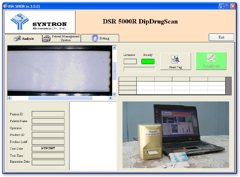
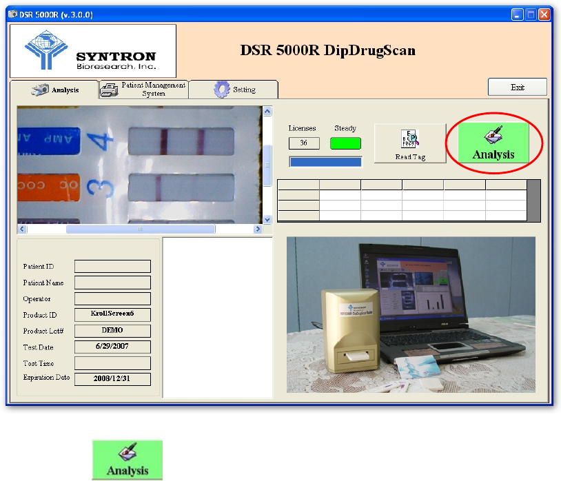
1. EXECUTE DSR 5000R DipDrugScan Reader Application
(A) Connect the USB cable from the reader to one of the computer’s USB port.
(B) EXECUTE the analysis software [DSR 5000R v.3.0.0.exe].
(Some computer requires more time to recognize the USB devices, if the software
asks you to plug in the Reader while you have really executed Step (A), you may
have to wait a little bit longer and then execute the software again)
(C) You can now see the main frame of the software as shown below:
3
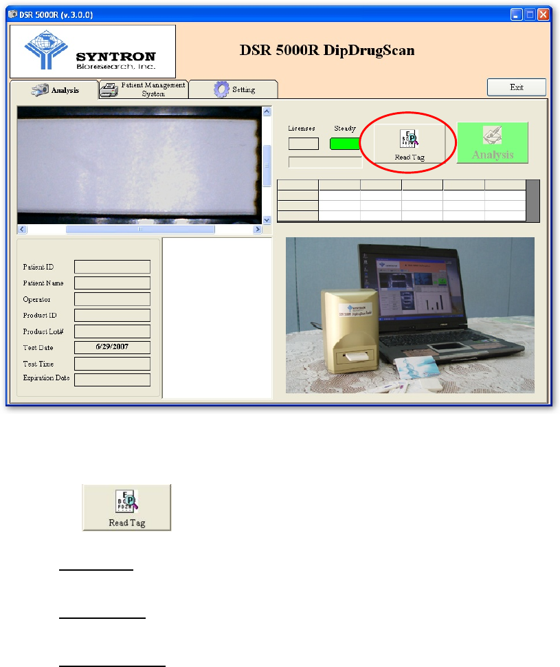
2. BEFORE ANALYSIS
Before analyze the strip, there are several parameters needed to be loaded from the
RFID calibration Tag, which comes with the tests.
(A) INSERT the RFID Tag into the back RFID slot of the DSR 5000R Reader.
(B) Press , the Reader will automatically loading:
Product ID: The kind of the test strip.
Product Lot#: The manufacturer lot number.
Expiration Date: The expiration date of the strip.
4
Test Date: The test date is generated automatically according to the clock of
the computer.
Test Time: The test time is generated automatically according to the clock of
the computer (it will be updated automatically when the button is
pressed.)
Licenses: The tests remained to be done according to your purchasing. To
make sure the record is not been changed, each test you bought is allowed to
be read once only.
(C) The button will lit on and the Reader is ready for use.
5
(D) Please be noted that RFID tag should only be used for the tests included inside the
same box. If you use the test from different box, please change the RFID tag by
simply remove it from the back slot. Using wrong RFID tag may result in wrong
test result.
(E) You don’t have to remove the RFID tag or press again if you keep
using the tests from the same box.
(F) It is strongly suggested that you calibrate the reader first before you do any test.
To calibrate the reader, please refer to the SETTING section (5(c))
6
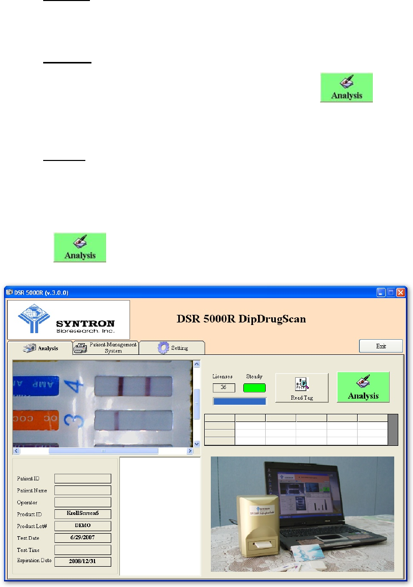
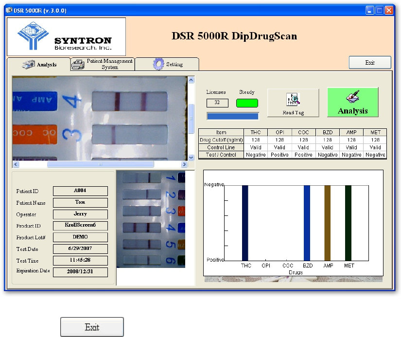
3. ANALYSIS (Analysis Page)
(A) Insert the cassette into the front slot of the DSR 5000R Reader, you may see the
live image appeared on the upper left preview window.
(B) Press .
7
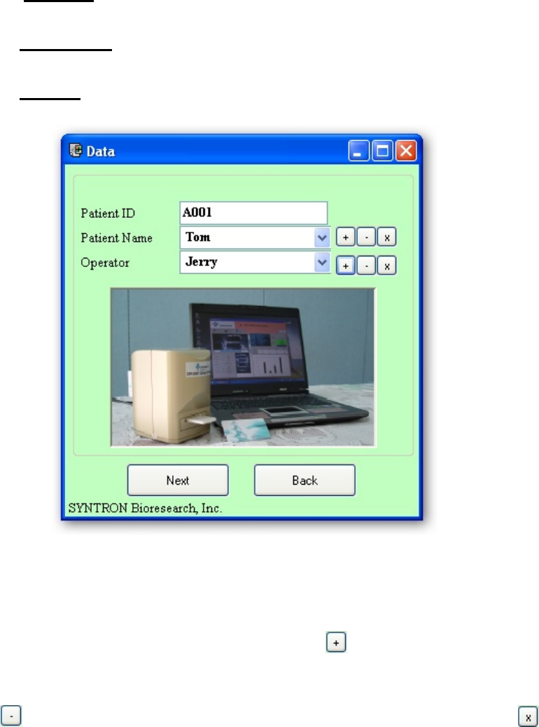
(C) A new window appears for you to type in manually:
Patient ID: The ID number of the patient or sample source.
Patient Name: The name of the patient or sample source.
Operator: The name of the operator who is executing this test.
(D) You can type in the names and ID in the input boxes or you can select from
previous data by clicking on the pull-down box. If you think you will use the
inputted name again later, you may click on the button to add the name into
the database. You can also remove the name from the database by clicking on the
button. You can also remove all data from the database by clicking the
button.
8
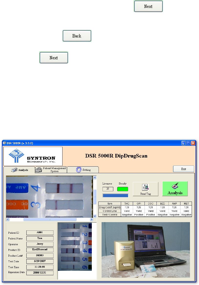
(E) If you are sure about the data you typed in, press to continue, the
number to license will then be deducted one. If you are not sure about the data
you typed in, please to return to previous step.
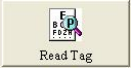
(F) When the button is pressed, the software will analyze automatically
using the parameters provided by RFID tag, including the kinds of tests, numbers
of tests, cut off values, etc. The analyzed result is shown in lower right corner
while the captured image is shown in the lower center area. “Negative” or
“Positive” results will be shown in the result table while the control lines are
shown as “Valid” for valid testing or “Invalid” for invalid testing.
9
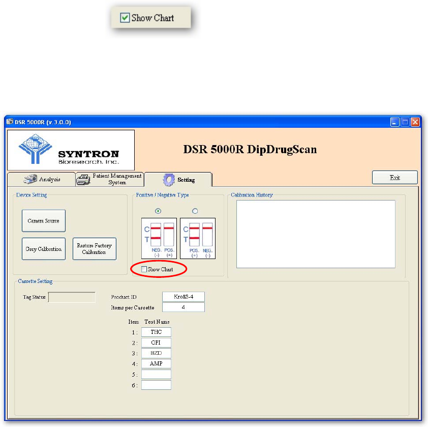
(G) If you want to show the results in bar chart format, go to the “Setting” page and
check on the box, the “Positive” or “Negative” results will
be shown in bar chart format as shown in next page. If you don’t want to see the
results in bar chart format, just uncheck the “Show Chart” box.
10
(H) Press to exit the software.
11
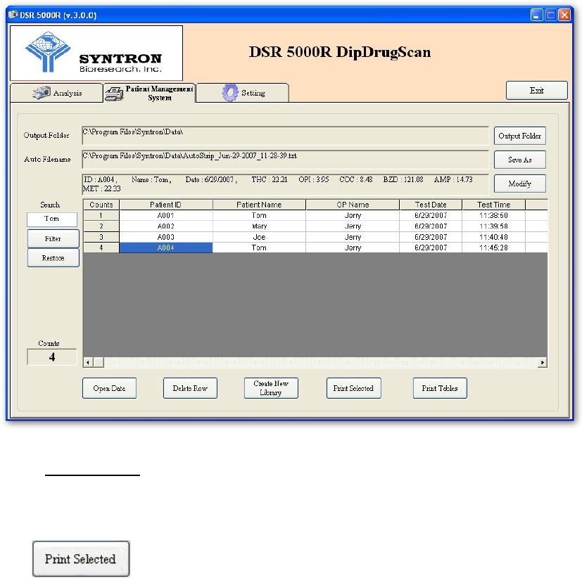
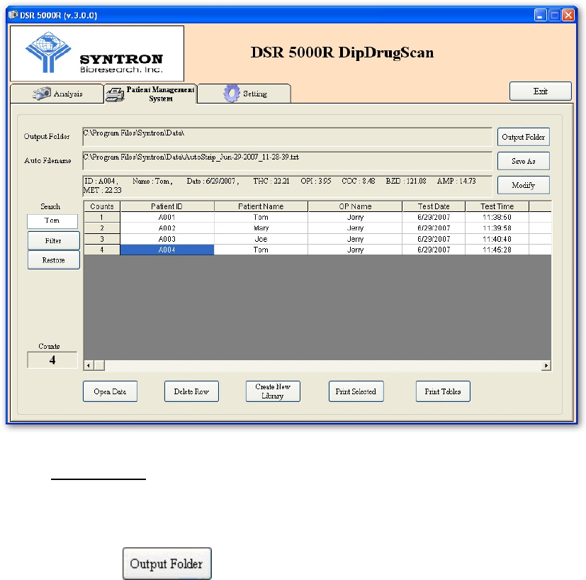
4. REPORTING (Patient Management System Page)
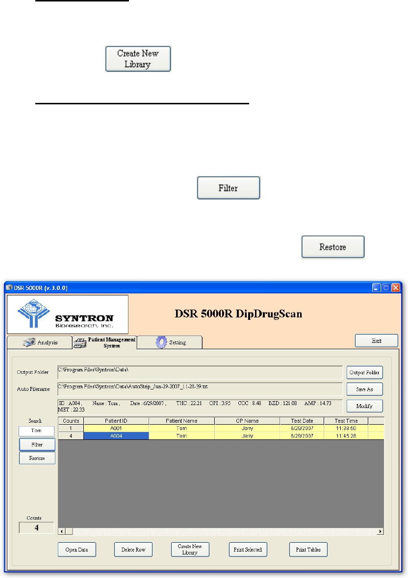
(A) The test result can be seen on “Patient Management System” page. The new
tested result is added to the row and given a new “count” to the batch, this batch
is then saved automatically under the same filename (please see SAVING FILES
section for more information).
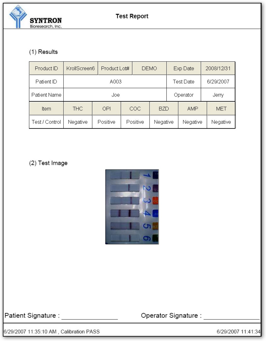
(B) Print Selected:
If there is only one result in a batch to be printed, you may use the
button.
12
13
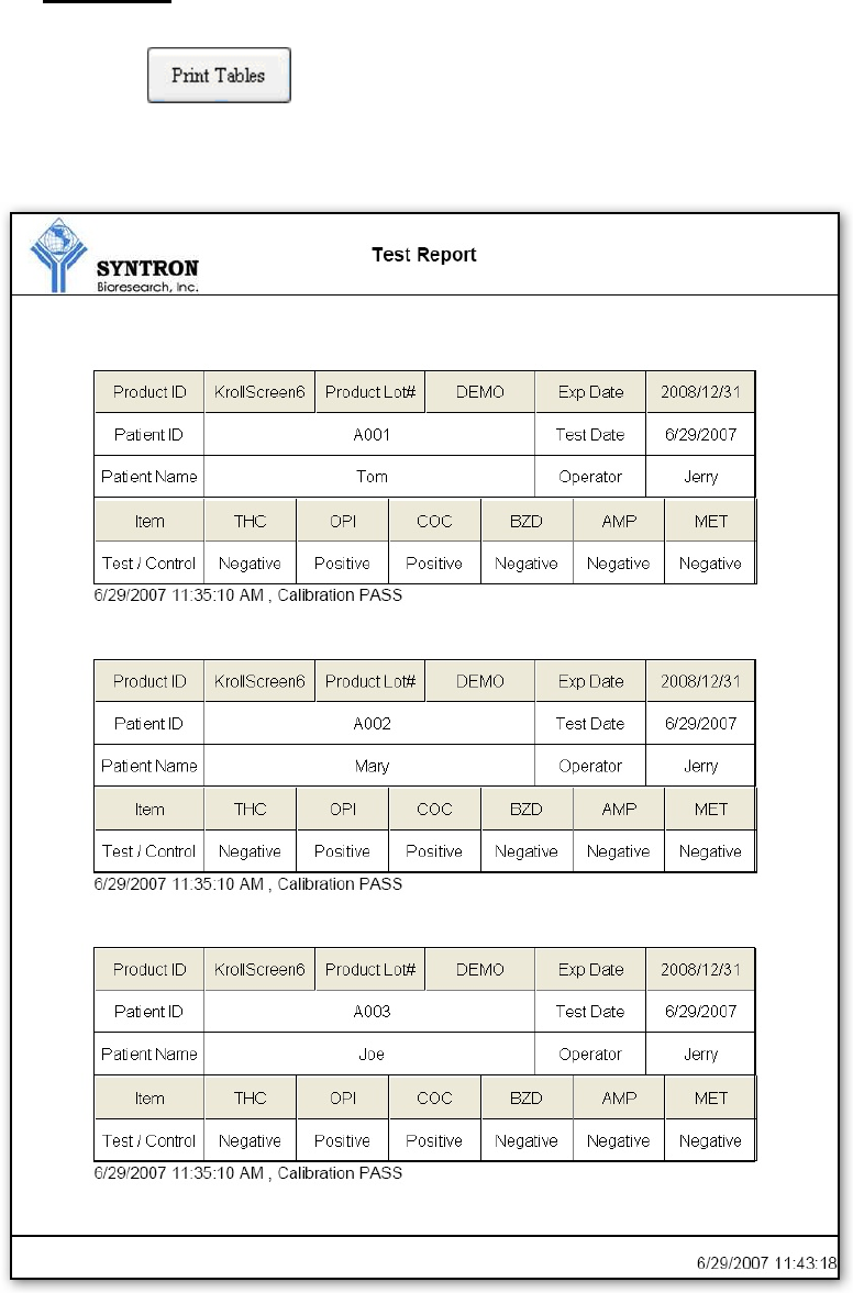
(C) Print Tables:
When button is clicked, all tested in this batch will be printed.
However, only tables are outputted.
14
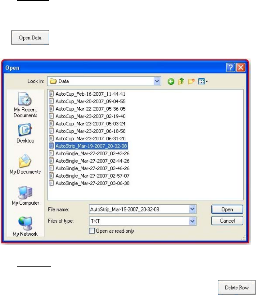
(D) Open Data:
You may open and check previous batch results by simply clicking the
button and choose any previous saved files:
(E) Delete Row:
You can delete a selected single experimental data by clicking
button. The highlighted data will be deleted from the batch.
15
(F) Create New Library:
You can delete all dada in the batch and create a new batch (as well as a new
file) by clicking button.
(G) Searching Specific Characters in File System:
You can choose to display some specific data only in the “Patient Management
System” page. To do so, just type in the specific characters you want to search in
the “Search Box” and click on the button. The search system will
look into the data base (in the Filename shown) and display them as shown below.
To restore all results (in the Filename shown), just clicking button.

16
Please be noted that the searching not only applies to the “Patient Name,” it
can also applies to the “Operator Name,” “Test Date,” and all characters saved in
the database.
(H) Press to exit the software
17
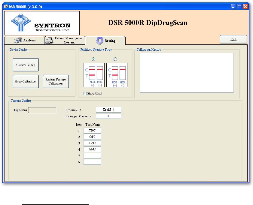
5. CONFIGURING (Setting Page)
The software is pre-adjusted for best condition with the hardware when shipped, it is
not recommended to make any adjustment.
(A) Positive/Negative Type :
It is according to the kind of the test. In some kind of tests, a line shown on the
T line position is treated as positive, and vice versa. It is preset inside the RFID tag.
18
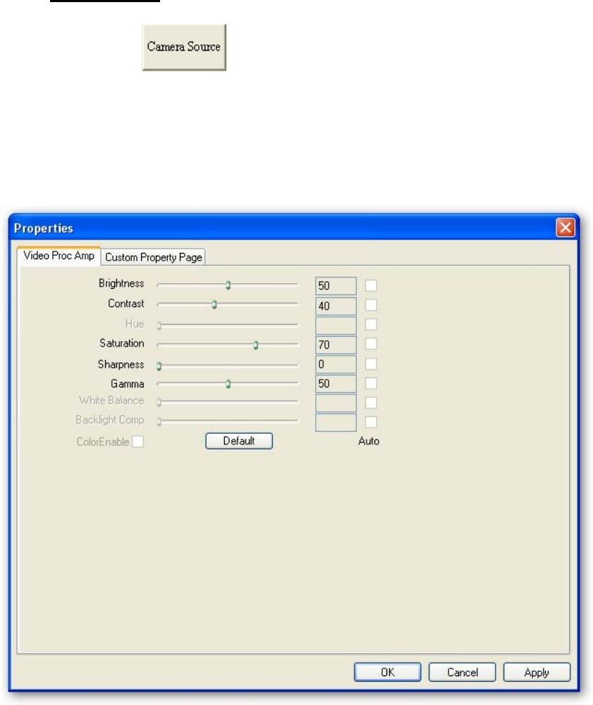
(B) Camera Source :
Click the button to set up the camera, the default camera is
[i-Spy PC Cam] or [HiCam USB 2.0 PCam S], it is also suggested to use the
original setting. It is strongly suggested not to change any camera properties, if you
need to change any coefficient, please consult with your supplier.
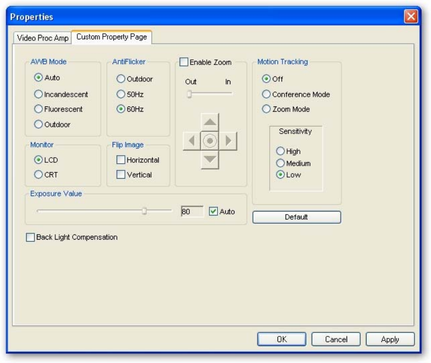
19
In some countries using 50Hz as the power supply frequency, it may be
necessary to adjust the AntiFlicker into 50Hz (default is 60Hz) if you see the
flickering in the display.
20
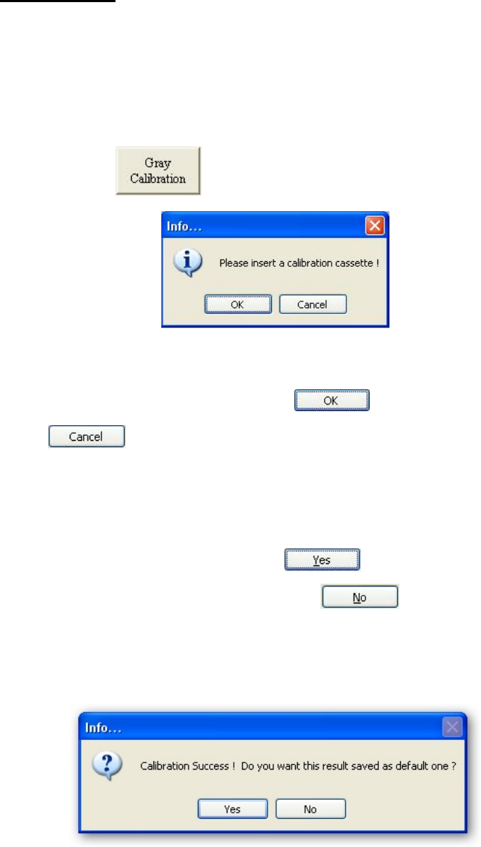
(C) Gray Calibration :
It is suggested that you calibrate the reader immediately when you execute this
software to get the best result out of the product. You may also calibrate the reader
again during the operation when you think it is necessary. To calibrate the reader:
(i) Press the button.
(ii) Insert the calibration cassette (included with the reader package) into the
front slot of the reader. Press to continue, or press
to abort the calibration.
(iii) Once calibrated, the new calibration curve will be used before the software
is turned off. If you want to save this new calibration curve and overwrite
the old calibration curve, press the button. If you just want to
use this new calibration curve, press button and the old
calibration curve will still be used next time when you turn on the software
(noted that the new curve is used before you turn off the software).
21
(iv) Please note that once you click button, the calibration history
will be recorded and the recent calibration date will be shown in your
future report. (same date shown in the “Last Calibration” box)
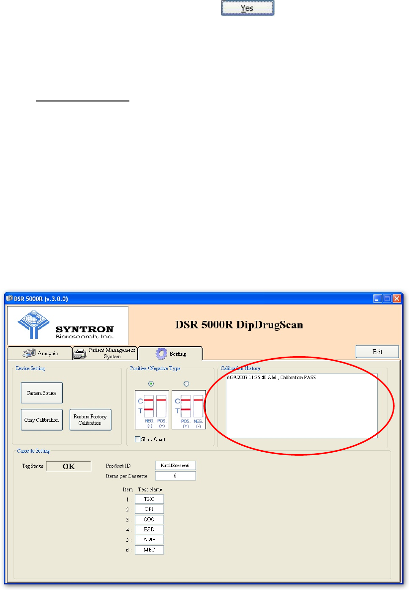
(D) Calibration History :
Whenever the Reader is calibrated, the system will check the calibration cassette
with the built in camera. If the gray scale values meet the calibration requirement,
the system passes the test. Otherwise, if the calibration fails, it may due to the
camera of stain on your calibration cassette. Please contact your vender for further
assistance. All tested results are automatically recorded in the Calibration History
window as sown in next page.
22
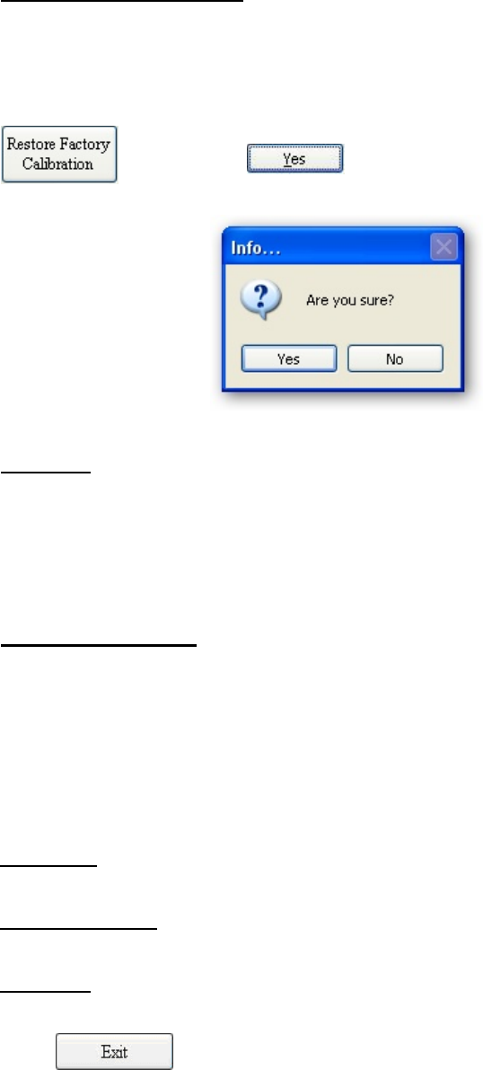
(E) Restore Factory Calibration :
If you calibrate the reader by accident or you are not sure about the calibration
result, you can always restore the original factory setting by pressing the
button. Press button if you are sure.
(F) Tag Status :
When RFID tag is correctly read, the “OK” sign will be shown, otherwise, the
“NG” sign will be shown for error reading RFID tag.
(G) The Cassette Variables:
Some cassette variables are seen in this page, these variables contain the
product information recorded in the RFID tag to correctly analyze the strip. Check
the information to confirm whether this is the right test you are going to analyze.
Product ID: The product ID for the test strip.
Items per Cassette: Numbers of tests per cassette.
Test Name: Name of the test.
(H) Press to exit the software
23
6. SAVING FILES
The analysis results are automatically saved once tests were done, however, you may
choose to change the filename.
(A) The File Path:
The default output folder is set to “C:\Program Files\Syntron\Data.” User can
click on the button to select a new output folder.
24
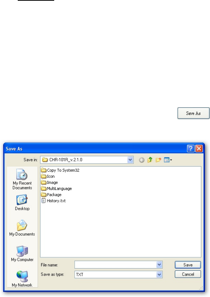
(B) The File Name:
The system will automatically generate a saved file once the first test in a batch
is done. The file name is “AutoStrip_Month-Day-Year_hh-mm-ss” to represent the
time of first analysis done in this batch. The format for the file is with the suffix
“.txt”. All tests in the same batch are saved under the same filename. If a new file
batch is necessary, you can click on the “Reset” button or simply quit the software
and re-execute the software again. A picture for each test will also be saved
automatically according to the report file.
If you choose to save the file with different filename, click
button to change the filename:
25
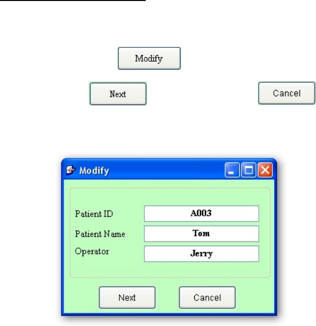
(C) Modify the patient information:
It is not suggested that you change the patient information. However, if it is to
be changed, click on the button to change the patient ID and/or
patient name. Click to continue or please to abort the
modification.
26
Software Installation Guide
1. Insert the INSTALLATION CD into the CD reader, the SETUP program will be
automatically executed.
2. If the SETUP program is not automatically executed, please locate the Setup.exe in
the root directory in the CD and execute it.
3. There are four software to be installed. First is the Camera and the second is DSR
5000R, the third one the Acrobat Reader and the last one is PDF Creator. The Setup
program will automatically install the Camera and DSR 5000R software (except
Acrobat Reader is for reading the PDF files and PDF Creator is just for printing out
reports on the computer instead of hard copies, you can install the Acrobat Reader
by locating the Acrobat Reader Folder and PDF Creator by locating the PDFCreator
Folder in the program folder or in the CD).
27
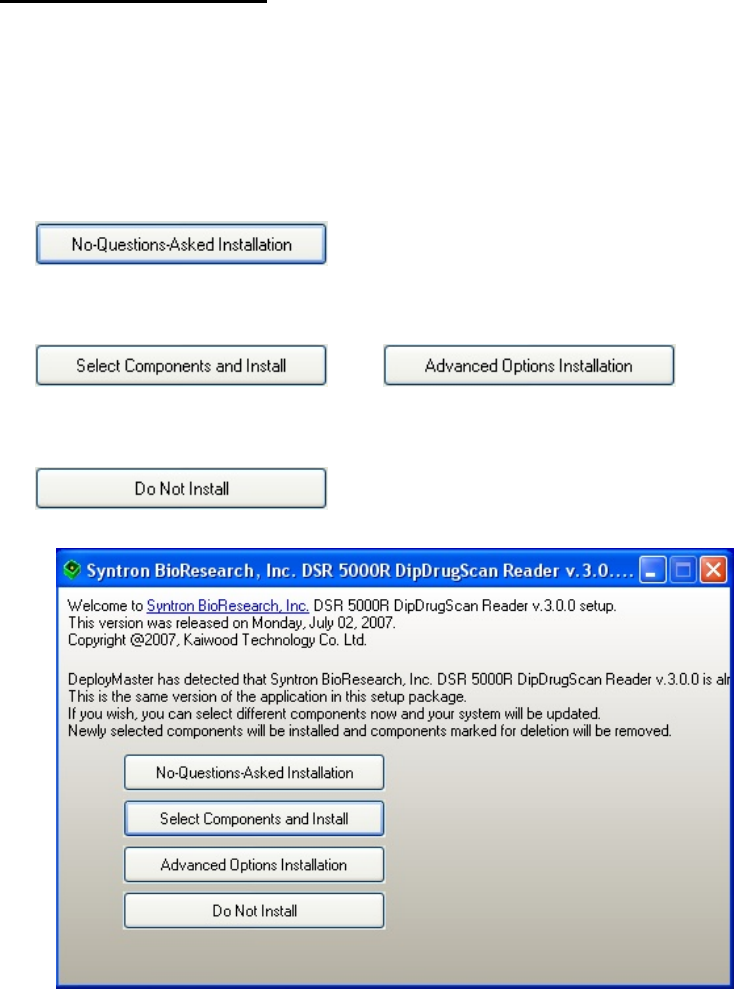
4. Installation the DSR 5000R
(A) After inserting the CD, the Setup.exe program will automatically execute. You
can find the Setup.exe in the root directory in the CD.
(B) You will see the following window, just simply click the
button to continue. You may also choose to
select the components to install (e.g. camera only) by clicking
, or to change
the default installation folder, or quit by clicking the
button.
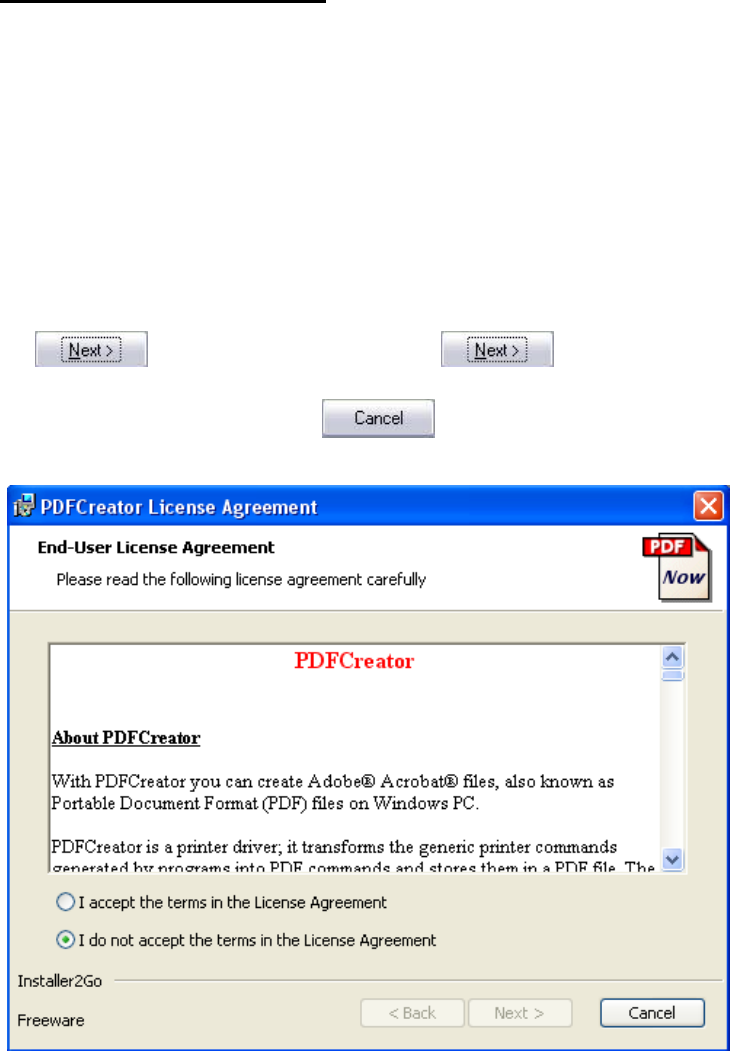
28
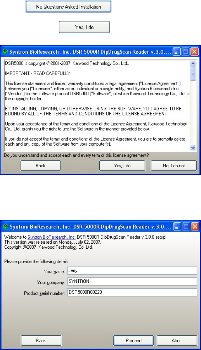
(C) When the is clicked, please accept the license
agreement by clicking
(D) The installation requires you to input your name, company, and the serial
number which you can find at the back of your DSR 5000 Reader.
29
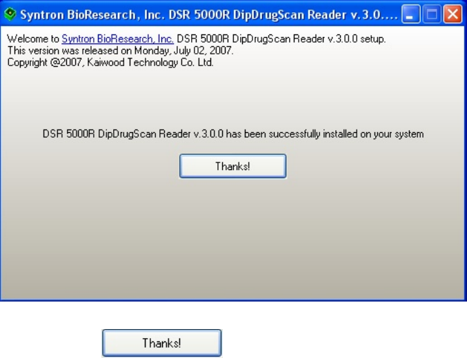
(E) After installing the main software, the window prompt:
(F) When you click , the installation will automatically install
the camera (Please see the Manually Install Camera Section)
30
5. Manually Install the Camera
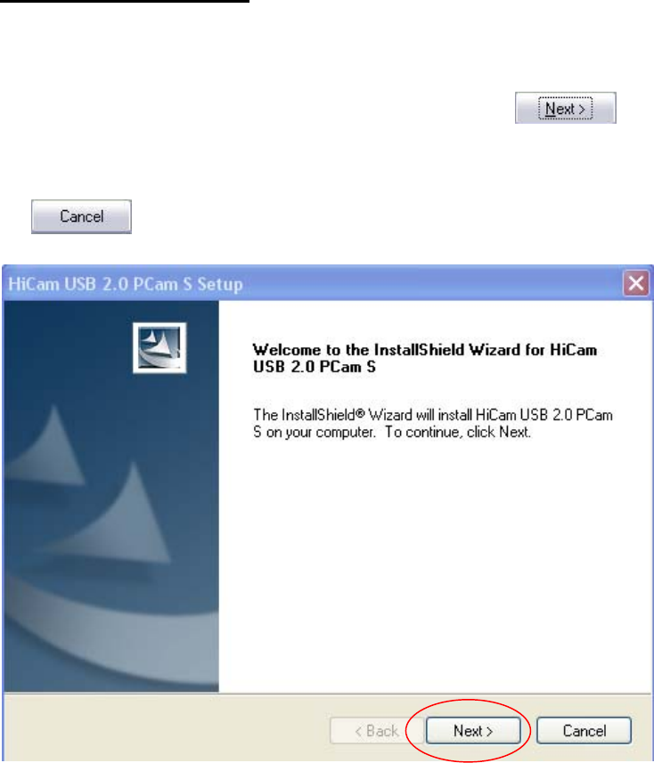
(A) Locate the Camera Folder in root\Camera. EXECUTE the Setup.exe program,
you will see the following window, just simply click the button as
circled in RED to continue. If not, you may choose to quit by clicking the
button.
31
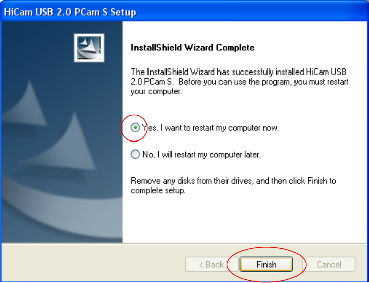
(B) The program will then guide you through all processes. When done, click YES
and press [Finish] button to restart your computer.
(C) If you have installed the camera before, it will prompt you whether you want to
uninstall the camera.
32
6. Manually install the PDF Creator
(Note that this is just an option, it should be installed only when you need to
preview your report on your computer screen when there is no real printer installed,
i.e. this software provides a preview function)
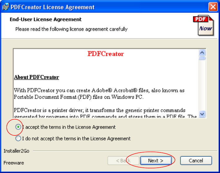
(A) You can find the PDFCreater.msi in root\PDFCreator directory. After executing
it, you will see the following window, check on [I accept] and then the
button will pop out, press to continue. You may
choose to quit by clicking the button.
33
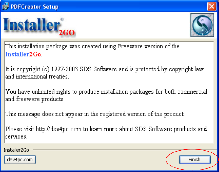
34
(B) The program will then guide you through all processes. When done,
press[Finish] button to exit

35
7. Uninstall
To uninstall the software, you may have to uninstall the DSR 5000R software and
Camera separately.
(A) EXECUTE the “Remove DSR 5000R DipDrugScan Reader” in SYTRON
folder (in Startup Menu / All Programs), the software will automatically
uninstall the DSR5000R software.
(B) EXECUTE the “Uninstall” in USB 2.0 Camera folder (in Startup Menu / All
Programs), the software will automatically uninstall the camera software.

36
Hardware Specification
Detector: CMOS Sensor
Dynamic Range: 8 bit
Transfer: USB 2.0 Plug-and-Play
Format: Drug Cassette
Power: USB Port with 500mA Power Supply
Computer requirement:
¾ OS: Windows 2000 or XP (Vista is working, but not fully supported yet)
¾ USB 2.0 port
¾ Windows resolution: 1024 x 768 (above)
¾ RAM: 512Mb or better
¾ It is suggested to execute the software individually, not with other software
running simultaneously.
Environment:
¾ Indoor Use
¾ Attitude: 2000m
¾ Operation Temperature: 5 ℃ ~ 40 ℃
¾ Humidity: Maximum 80%RH at 31℃ decreasing to 50%RH at 40℃
¾ Away from high radio frequency interference (such as base station, etc.)
¾ Pollution Degree: 2
Maintenance:
¾ Keep the device outlook clean by using soft towel, it is not necessary to clean
inside.
¾ In case of calibration error or any problems, please contact Syntron
BioResearch Inc. (www.syntron.net) for nearest service provider.
37
Labels:
Company: Syntron BioResearch Inc.
2774 Loker Avenue West, Carlsbad, CA 92008, USA
www.syntron.net
Manufacturer: Kaiwood Technology Co., Ltd..
5F, No12, Ln31, Sec1 Huondung Rd., Hsinshi Township,
Southern Taiwan Science Park,
Tainan County 741, Taiwan
www.kaiwood.com.tw
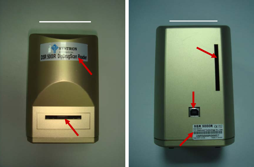
Front View Rear View
Device Label
Cassette Inlet
RFID Tag Inlet
USB Connect
Manufacturer Label
38
Patterns
Optical Optimization Method
¾ Taiwan, 196357
¾ China, 215732
CCD-Based Biochip Reader
¾ Taiwan, I 226437
¾ USA, 7173707
¾ China, 03156851.3 (Pending)
Cartridge Type Reagent Chip Reader
¾ Taiwan, I 278867
¾ USA, 11/542179 (Pending)
¾ China, 200610081459.4 (Pending)
Image Detection Method for Diagnostic Plates
¾ Taiwan, 096112275 (Pending)
¾ China, 200710106122.9 (Pending)

39
Certification
¾ Report No: 06-07-MAS-040
¾ The equipment is IVD medical equipment
FDA
¾ Product Code: JJQ
¾ Device Class: 1
¾ Owner/Operator Number: 9096712
¾ Date of Listing: 01/03/07
¾ Reference:http://www.accessdata.fda.gov/scripts/cdrh/cfdocs/cfRL/listing.cf
m?&ID=103087
FCC
¾ ID No: VGG-KWCHR001
ISO13485
¾ Certificate No: GB06169533
ISO9001:2000
¾ Certificate No: GB06169534
GMP
¾ Medicine No: 0960312056
¾ Manufacture No: Medical Device First 001887
40
FCC Notices
This device complies with Part 15 of the FCC Rules. Operation is subject to the following
two conditions: (1) this device may not cause harmful interference, and (2) this device
must accept any interference received, including interference that may cause undesired
operation.
CAUTION: Change or modification not expressly approved by the party responsible for
compliance could void the user’s authority to operate this equipment.
This equipment has been tested and found to comply with the limits for a Class B
digital device, pursuant to Part 15 of the FCC Rules. These limits are designed to
provide reasonable protection against harmful interference in a residential installation.
This equipment generates, uses and can radiate radio frequency energy and, if not
installed and used in accordance with the instructions, may cause harmful interference to
radio communications. However, there is no guarantee that interference will not occur in
a particular installation. If this equipment does cause harmful interference to radio or
television reception, which can be determined by turning the equipment off and on,
theuser is encouraged to try to correct the interference by one or more of the following
measures:
--Reorient or relocate the receiving antenna.
--Increase the separation between the equipment and receiver.
--Connect the equipment into an outlet on a circuit different from that to which the
receiver is connected.
--Consult the dealer or an experienced radio/TV technician for help.
CAUTION:
Any changes or modifications not expressly approved by the grantee of this device could
void the user's authority to operate the equipment.
RF exposure warning:
The equipment complies with FCC RF exposure limits set forth for an uncontrolled
environment. The equipment must not be co-located or operating in conjunction with any
other antenna or transmitter.