Kaiwood Technology KWCHR001 STRIP READER User Manual QPR 2500R Eng v3 1 0
Kaiwood Technology Co., Ltd. STRIP READER QPR 2500R Eng v3 1 0
UserManual.wiki
>
Kaiwood Technology
>
KWCHR001 User Manual
>
QPR 2500R Users Manual
Contents
1.
DSR 5000R Users Manual
2.
QCR 6000R Users Manual
3.
QPR 2500R Users Manual
QPR 2500R Users Manual
Navigation menu
Upload a User Manual
Namespaces
Wiki Guide
HTML
PDF
Info
Views
User Manual
Discussion / Help
Navigation

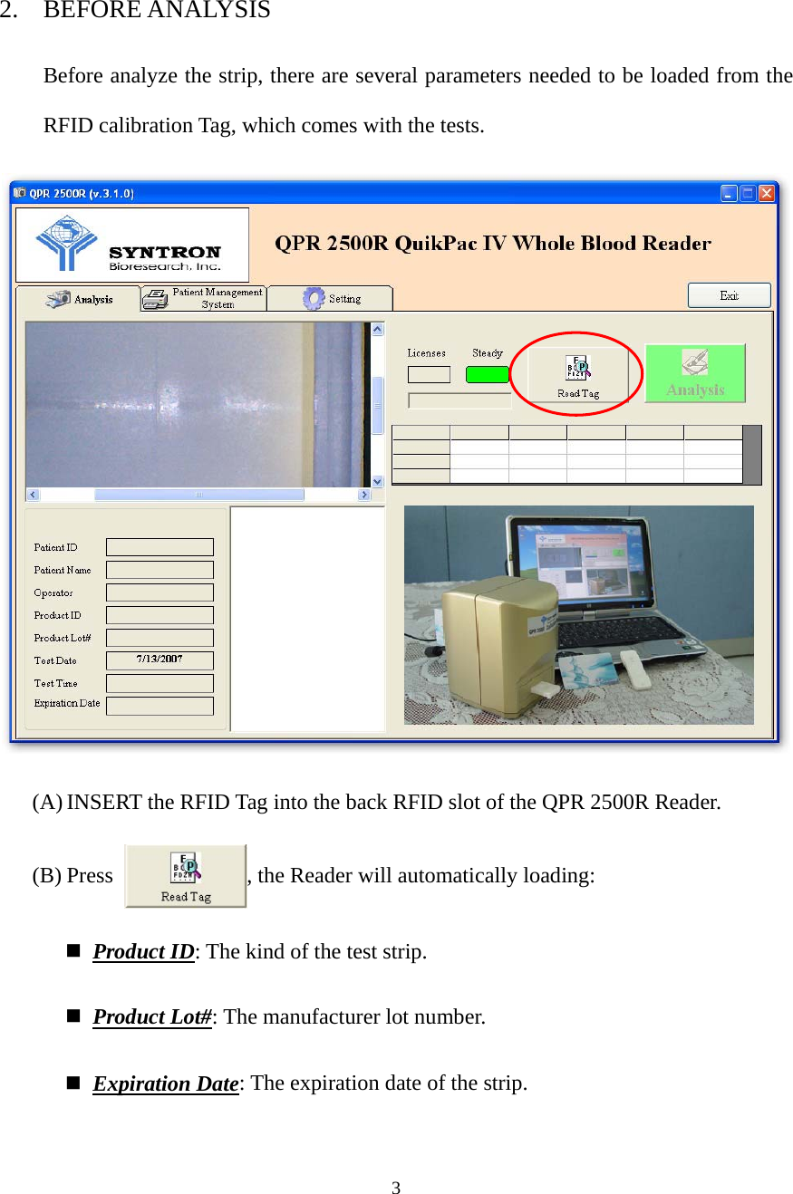
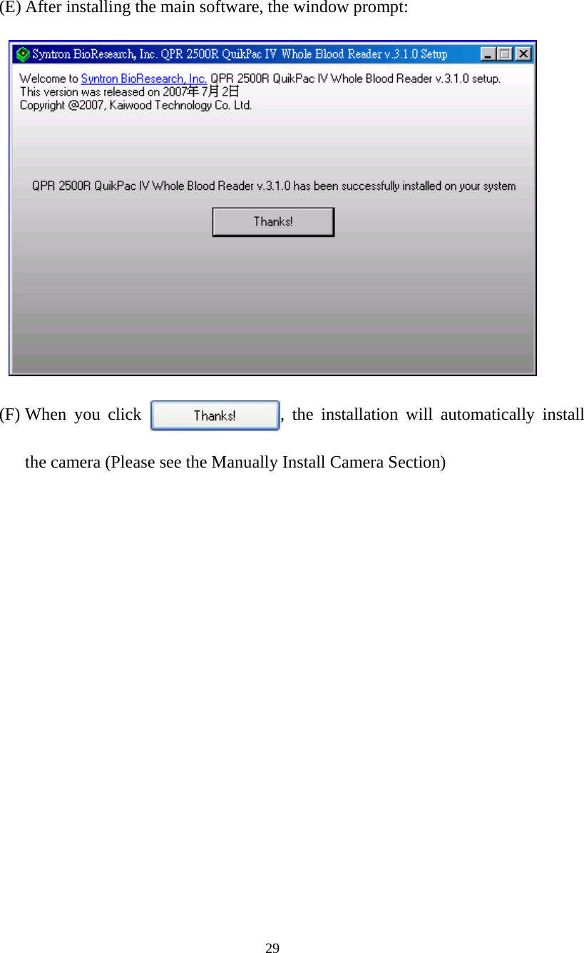
![2 Software User Manual 1. EXECUTE QPR 2500R QuikPac IV Whole Blood Reader Application (A) Connect the USB cable from the reader to one of the computer’s USB port. (B) EXECUTE the analysis software [QPR 2500R v.3.1.0.exe]. (Some computers require more time to recognize the USB devices, if the software asks you to plug in the Reader while you have really executed Step (A), you may have to wait a little bit longer and then execute the software again) (C) You can now see the main frame of the software as shown below:](https://usermanual.wiki/Kaiwood-Technology/KWCHR001.QPR-2500R-Users-Manual/User-Guide-828684-Page-3.png)
![18 (B) Camera Source : Click the button to set up the camera, the default camera is [i-Spy PC Cam] or [HiCam USB 2.0 PCam S], it is also suggested to use the original setting. It is strongly suggested not to change any camera properties, if you need to change any coefficient, please consult with your supplier.](https://usermanual.wiki/Kaiwood-Technology/KWCHR001.QPR-2500R-Users-Manual/User-Guide-828684-Page-19.png)
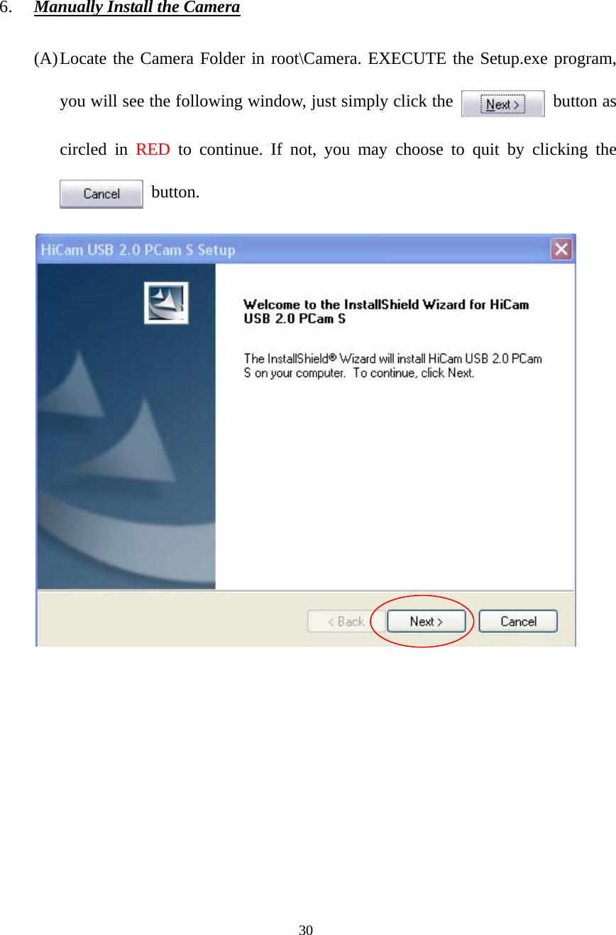
![31 (B) The program will then guide you through all processes. When done, click YES and press [Finish] button to restart your computer. (C) If you have installed the camera before, it will prompt you whether you want to uninstall the camera.](https://usermanual.wiki/Kaiwood-Technology/KWCHR001.QPR-2500R-Users-Manual/User-Guide-828684-Page-32.png)
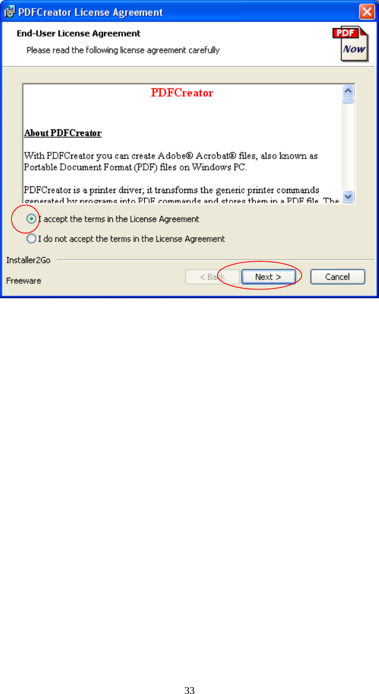
![32 7. Manually install the PDF Creator (Note that this is just an option, it should be installed only when you need to preview your report on your computer screen when there is no real printer installed, i.e. this software provides a preview function) (A) You can find the PDFCreater.msi in root\PDFCreator directory. After executing it, you will see the following window, check on [I accept] and then the button will pop out, press to continue. You may choose to quit by clicking the button.](https://usermanual.wiki/Kaiwood-Technology/KWCHR001.QPR-2500R-Users-Manual/User-Guide-828684-Page-33.png)
![34 (B) The program will then guide you through all processes. When done, press[Finish] button to exit](https://usermanual.wiki/Kaiwood-Technology/KWCHR001.QPR-2500R-Users-Manual/User-Guide-828684-Page-35.png)