Kapsch Trafficcom 9160 ITS - DSRC Road Site Unit User Manual THb 47000001566 02x
Kapsch Trafficcom AG ITS - DSRC Road Site Unit THb 47000001566 02x
User and Installers manual

Technical Manual
Roadside ITS Station RIS-9160-xx0x
This device provides communication protocols based on
IEEE WAVE or ETSI ITS G5 Standards
Doc No. 47000001566
Version 02

47000001566-THb-02
Order number: 47000001566
Document type THb
Document issue 02
Document status released
Date of issue 2018-02-01
Valid from
Author: Tugrul Güner, Alfred Brendinger
Assessor: Alfred Brendinger, Peter Ullrich, Heinz Liebhart, Alexander Paier, Herbert Diemling
Release: Tugrul Güner
Disclaimer and Limitation of Liability
The products described in this manual are provided “as is” and without any warranties of any kind,
either express or implied. Kapsch TrafficCom disclaims all warranties, express or implied,
including, but not limited to, warranties of title, legality or non-infringement or misappropriation of
any intellectual property rights of third parties or implied warranties of merchantability or fitness
for a particular purpose. Under no circumstances will Kapsch TrafficCom (including its affiliates,
licensors, contractors, suppliers, assignees, subsidiaries, and the respective officers, directors,
employees, shareholders, agents and representatives of each of them) be liable for any expenses,
fees, claims, damages or losses in any way relating to or arising out of the products described in
this manual. Applicable law may not allow certain warranty exclusions, so one or more of the
above disclaimers may not apply to you.
Copyright Kapsch TrafficCom AG 2018
Duplication as well as utilization of contents of this documentation are illegal without our explicit consent.

Page 3 of 36
47000001566-THb-02
Table of Contents
Page
Associated Documents 6
Information About This Document 6
Text Conventions ............................................................................................ 7
Important Text Elements ................................................................................. 7
Abbreviations ................................................................................................... 8
Warning to Users in the United States 9
Regulatory Information 10
Software Licenses 11
Safety Instructions 11
Maintenance Instructions 11
Inspection Instructions 11
Environmental Information 12
Visual Inspection 12
Installation Instructions 12
General Information 12
Definitions ...................................................................................................... 12
System Overview 13
Performance Overview .................................................................................. 13
US Version .................................................................................................... 13
European Version .......................................................................................... 13
System Architecture ...................................................................................... 14
Compact Architecture ........................................................................................14
System Interfaces ..............................................................................................15
Product versions 19
Installation 20
Mounting ........................................................................................................ 20
Device without a mounting plate ........................................................................21
Device with mounting plate “M” ..........................................................................22
Device with mounting adapter “W” .....................................................................23
Electrical Installation...................................................................................... 24
Signals at the LAN/PoE System-Connector .......................................................24
System cable connection ...................................................................................25
Product Specifications ................................................................................... 28
Mechanical Dimensions ................................................................................ 31
Conformity 32
Standards ...................................................................................................... 32
Statement of Conformity ............................................................................... 34
Optional Equipment 35
Mounting Bracket for RIS-9160 ..................................................................... 35
Protection caps and termination plugs .......................................................... 36

Page 4 of 36 Technical Manual | Roadside ITS Station RIS-9160-xx0x
47000001566-THb-02
Table of Figures
Page
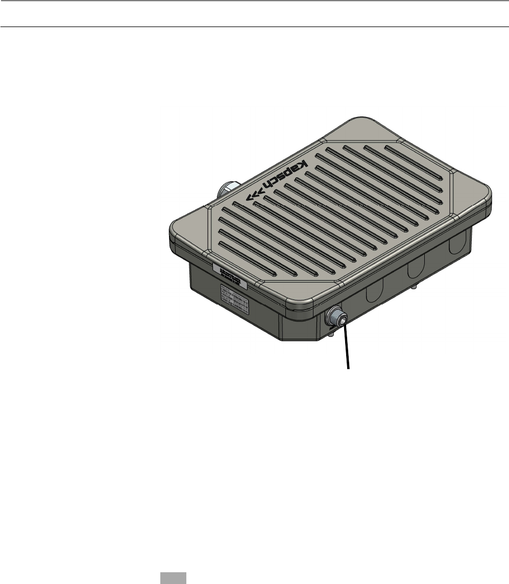
Figure 1 Roadside ITS Station RIS-9160 ..................................................... 13
Figure 2 Functional block diagram ................................................................ 15
Figure 3 System Interfaces ........................................................................... 15
Figure 4 Auxiliary antenna ports RIS-9160 ................................................... 16
Figure 5 Position of the Status LEDs ............................................................ 17
Figure 6 RIS-9160 without a mounting plate ................................................. 21
Figure 7 RIS-9160 with mounting plate “M” – rear view ............................... 22
Figure 8 RIS-9160 with mounting plate “M” – side view ............................... 22
Figure 9 RIS-9160 with Mounting adapter „W” ............................................. 23
Figure 10 Remove original gasket ................................................................ 26
Figure 11 Position of the sealing ................................................................... 26
Figure 12 Cable Connection Mounting Details ............................................. 26
Figure 13 Direction of the Rubber Gasket..................................................... 27
Figure 14 RIS-9160 with connected system cable ........................................ 27
Figure 15 Dimensions of RIS-9160 without mounting plate .......................... 31
Figure 16 Dimensions of RIS-9160 with mounting plate ”M” ........................ 31
Figure 17 Dimensions of RIS-9160 with mounting adapter “W” ................... 32
Figure 18 Mounting Bracket with safety wire ................................................ 35
Figure 19 Dimensions and drilling plan of the Mounting Bracket .................. 35

Technical Manual | Roadside ITS Station RIS-9160-xx0x Page 5 of 36
47000001566-THb-02
List of Tables
Table 1 Available Device versions of RIS-9160-xx0x ..................................... 6
Table 2 Text Formats and their Meaning ....................................................... 7
Table 3 D1 – General Status LED ................................................................ 17
Table 4 D2 – Power LED ............................................................................. 18
Table 5 RIS-9160 device versions ................................................................ 19
Table 6 LAN/PoE connector signals ............................................................ 24
Table 7 Connector assembly parts .............................................................. 25
Table 8 Standards ........................................................................................ 32
Table 9 Protection caps and termination plugs ............................................ 36

Page 6 of 36 Technical Manual | Roadside ITS Station RIS-9160-xx0x
47000001566-THb-02
Associated Documents
none -
Information About This Document
This Manual is the common Description, Installation and Service Manual for
the device family RIS-9160-xx0x with Kapsch part numbers 34034340xxx.
Available device versions are listed in Table 1.
Part No. Device name
Additional device name
Description
34034340000 RIS-9160-1A0M
K25104P000000000000
Roadside unit with mounting
plate “M”.
34034340001 RIS-9160-1A00
K25104P000000000000
Roadside unit without a
mounting plate.
34034340002 RIS-9160-1A0W
K25104P000000000000
Roadside unit with mounting
adapter “W”.
This document is addressed to qualified staff only. Qualified staff have the
appropriate knowledge in the scope of electrical engineering.
This Technical Manual shall be carefully read before installation.
Customer specific installation guidelines are not described within this
document.
All dimensions used in this document are in metric system except otherwise
indicated.
Objective
Table 1 Available Device versions
of RIS
-
9160
-
x
x
0
x
Audience
Preparations
Dimensions
Technical Manual | Roadside ITS Station RIS-9160-xx0x Page 7 of 36
47000001566-THb-02
Text Conventions
Visual aids and standard text formats in this manual help the reader to locate
and identify information easily.
Typographical formats:
Style Used for
bold Accentuations
italics Labelling and cross-references
CAPITAL LETTERS Acronyms
Important Text Elements
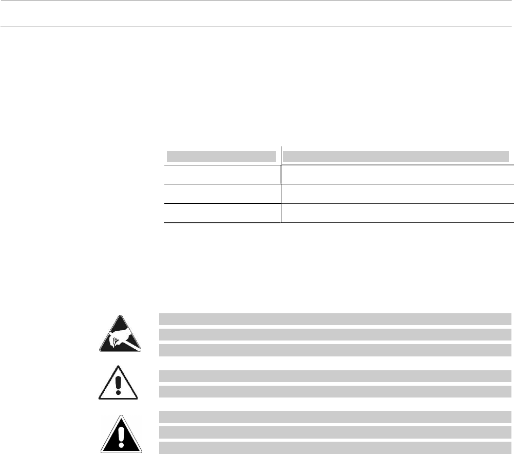
This manual contains specific Caution and Warning statements. These shall
be interpreted as follows:
Attention: This warning indicates that the device may be affected by
Electrostatic Discharge. Appropriate precautions must be made to avoid
damage to the device.
Caution: A caution sign indicates concerns about a procedure which
may lead to equipment damage or violation of regulatory requirements.
Warning: indicates a potential danger that requires correct procedures
or practices in order to prevent injury to humans or damage to the
equipment.
Table 2
Text
F
ormats and
t
heir
M
eaning
Attention
Caution
Warning

Page 8 of 36 Technical Manual | Roadside ITS Station RIS-9160-xx0x
47000001566-THb-02
Abbreviations
ACR Adjacent Channel Rejection
BT Bluetooth
DL Downlink direction (Information from RIS-9160)
DSRC Dedicated Short Range Communication
EIRP Equivalent Isotropic Radiated Power
GB Giga Byte
GNSS Global Navigation Satellite System
GPIO General Purpose Input or Output
LOS Line of Sight
LTE Long Term Evolution, 4th generation cellular communication
technology
OBU On Board Unit
NACR Non Adjacent Channel Rejection
NLOS Non Line of Sight
PoE Power over Ethernet
PPS Pulse Per Second
RSU Roadside Unit
RIS Roadside ITS Station
SSD Solid State Disk
UL Uplink direction (Information to RIS-9160)
WAVE Wireless Access in a Vehicular Environment, a term used by
IEEE 1609.x series of standards
WLAN Wireless Local Area Network
WWAN Wireless Wide Area Network

Technical Manual | Roadside ITS Station RIS-9160-xx0x Page 9 of 36
47000001566-THb-02
Warning to Users in the United
States
The hardware referred to in this document allow selection of frequency bands
and transmit power levels that may not comply with the regulatory body that
governs spectrum policy where the hardware is being used.
The operator is required to apply for and obtain a 47 CFR Part 90 geographic
area license from the FCC that has specified eligibility requirements to operate
this device in the United States (47 CFR Part 90.375). See product label for
FCC ID number.
Individual devices have to be registered. Such licenses serve as a prerequisite
to registering individual devices located within the licensed geographic area.
Licensees must register each installation in the Universal Licensing System
(ULS) before operating a 5.9GHz DSRC Roadside Unit (RSU).
For further information about DSRC regulations in the US please refer to
https://www.fcc.gov/
Local Regulations
License Required

Page 10 of 36 Technical Manual | Roadside ITS Station RIS-9160-xx0x
47000001566-THb-02
Regulatory Information
The device versions referred to in this document comply with Part 15 of the
FCC Rules. Operation is subject to the following two conditions:
1. This device may not cause harmful interference, and
2. this device must accept any interference received, including interference
that may cause undesired operation.
Changes or modifications made to this equipment not expressly approved by
Kapsch may void the FCC authorization to operate this equipment.
Note: This equipment has been tested and found to comply with the
limits for a Class B digital device, pursuant to Part 15 of the FCC Rules.
These limits are designed to provide reasonable protection against
harmful interference in a residential installation. This equipment
generates uses and can radiate radio frequency energy and, if not
installed and used in accordance with the instructions, may cause
harmful interference to radio communications. However, there is no
guarantee that interference will not occur in a particular installation. If
this equipment does cause harmful interference to radio or television
reception, which can be determined by turning the equipment off and
on, the user is encouraged to try to correct the interference by one or
more of the following measures:
• Reorient or relocate the receiving antenna.
• Increase the separation between the equipment and receiver.
• Connect the equipment into an outlet on a circuit different from
that to which the receiver is connected.
• Consult the dealer or an experienced radio/TV technician for help.
This equipment complies with FCC radiation exposure limits set forth for an
uncontrolled environment. This equipment should be installed and operated
with minimum distance of 20 cm (8 inches) between the radiator and a human
body. Failure to do so could result in bodily injury or death.
This transmitter must not be co-located or operating in conjunction with any
other antenna or transmitter.
Notice
Notice
Class B Digital Device
Radio Frequency Radiation
Exposure Information
Technical Manual | Roadside ITS Station RIS-9160-xx0x Page 11 of 36
47000001566-THb-02
Software Licenses
This product may contain software portions including technologies used under
third party license, and are copyrighted. Notices, Terms and Conditions
pertaining to third party software are located at
http://www.kapsch.net/us/en/ktc/portfolio/products_and_components/Pages/
default.aspx
Safety Instructions
Caution: Cables shall not be bent to a smaller radius than specified by
the cable manufacturer. For cables listed in this manual the dending
radius shall be larger than 2 inches (5cm)
Caution: It is necessary to connect the device to ground with a low
impedance connection.
This reminder is provided to call the systems installer's attention to
Section 820.93 of the NFPA 70® National Electrical Code ® 2008
Edition, which provide guidelines for proper grounding and, in
particular, specify that the coaxial cable shield shall be connected to the
grounding system of the building, as close to the point of cable entry as
practical.
Note: This reminder applies when the GPS antenna is installed remote
using a coax-cable between the RIS-9160 and the GPS antenna.
Maintenance Instructions
The Roadside ITS Station RIS-9160 need no regular electrical maintenance.
Inspection Instructions
Warning: Regular inspection of installed equipment is mandatory and
shall be in accordance with the local safety regulations for equipment
installed on the roadside.
Handling of Cables
Grounding
Note to GPS System
Installer
Regular Inspection

Page 12 of 36 Technical Manual | Roadside ITS Station RIS-9160-xx0x
47000001566-THb-02
Environmental Information
RIS-9160 equipment set consists of material that can be recycled by
specialized companies. Please observe the local regulations regarding the
disposal of packaging material and waste electronic equipment.
The device is protected against environmental influences by NEMA 4X (IP67)
enclosure. No additional protection measures are required for outdoor
installation.
The specified protection class is only provided when each connector is either
closed by a mounted accessory (antenna or cable) with the same protection
class or when unused, the connector has to be closed with a dedicated plug
which is specified within this document.
The device is shipped packed and each antenna port of the device is protected
against dust with a plastic dust protection which must be removed before
installation.
Exposure of the device to direct solar radiation may additionally increase the
case temperature. If the requirement for acceptable operational temperature
range cannot be satisfied an application specific sun cover must be used.
Visual Inspection
Always check the shipment for completeness and possible damage. If the
content is incomplete or damaged, a claim should be filed with the carrier
immediately and contact your local Kapsch office.
Installation Instructions
For information regarding applications for and installation of the products
described in this manual, please see the application notes.
General Information
Definitions
The size of the communication zone is defined by the area where
communication with another device (e.g., OBU) is reliable. The size of the
communication zone is mostly influenced by the mounting height and
mounting angle of the antennas, the antenna utilized, the transmit power level
used and environmental effects e.g. buildings, traffic signs, trees and receiving
vehicles communication characteristics (receiver sensitivity, antenna, … )
etc..
Recycling
Environmental
Requirements
Transport
Communication Zone
Technical Manual | Roadside ITS Station RIS-9160-xx0x Page 13 of 36
47000001566-THb-02
System Overview
The RIS-9160 implemented in roadside systems supports reliable data
exchange with standard (IEEE WAVE or ETSI ITS G5) compliant Onboard
Units (OBUs).
Performance Overview
Product operates in outdoor and roadside environments
Weather proof, robust and compact housing
US Version
IEEE WAVE/802.11p compliant DSRC transceiver RIS-9160
Compatible with IEEE WAVE/802.11p compliant OBUs
European Version
ETSI ITS G5 compliant roadside transceiver RIS-9160
Compatible with ETSI ITS G5 compliant OBUs
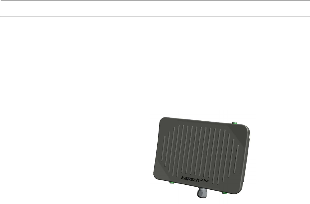
Figure 1
Roadside ITS Station RIS
-
9160

Page 14 of 36 Technical Manual | Roadside ITS Station RIS-9160-xx0x
47000001566-THb-02
System Architecture
The Roadside ITS Station RIS-9160 architecture is optimized for easy and
fast installation and commissioning. The applied architecture is used for
setups with a minimum of auxiliary equipment needed on the roadside. The
device includes all functionality to run IEEE WAVE or ETSI ITS G5
functionality.
Compact Architecture
The applied architecture has the highest flexibility for different system setups.
It can be scaled for different needs of the customer.
Common system features:
GB Ethernet based system interface
PoE power supply of the device
Device is internally protected against surges on data and power lines
GPS antenna interface for positioning and time synchronization
Two 5.9 antenna interfaces
LED status indication
Preconfigured optional features:
Internal mSATA SSD for memory extension
Internal µSD memory card for memory extension
Application specific mounting plates
Optional features but not available in the described device family in this
document:
GPIO interface (3x in, 3x out)
External 24-48V DC supply in addition to or instead of the PoE+ supply.
WWAN interface
WLAN interface
BT interface
Note: All options need to be installed in the production before delivery. The
availability of the options is depending on the product roadmap and customer
demand.
Scope
System Structure
Technical Manual | Roadside ITS Station RIS-9160-xx0x Page 15 of 36
47000001566-THb-02
Device parameter setting & provisioning
Web server*
Firmware provisioning
Self-test / Supervision
Logging*
Monitoring*
Linux OS
WAVE 1609
5.9 API
5.9 application layer
IEEE 802.11p radio (x2*)
ETSI ITS G5
Computer HW platform
TCP/IP Services
Watchdog
Temp Sensor
Security Services
Real Time Clock
Administration Services
Unique Serial No
ETH (PoE) GPIO*
WLAN* WWAN*BT*
Operation & Maintenance
External Interfaces
Platform & Resources & Protocols
5.9GHz radio communication
Modular HW & extentions
5.9GHz GNSS
* Option
5.9GHz
LEDs Ext.Power*
WWAN*
BT*
WLAN*
GNSS
SSD* µSD* USB* mPCIe*
Modular internal extentions
External radio interface extensions
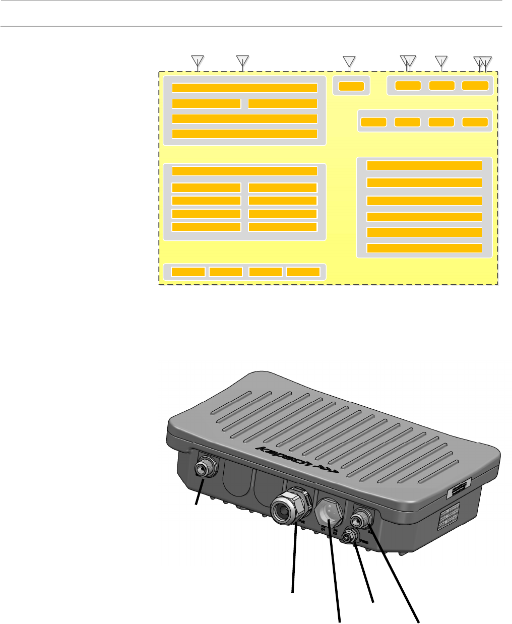
System Interfaces
Figure
2
Functional block diagram
Figure
3
System Interfaces
5.9GHz
Antenna port 1
5.9GHz
Antenna port 2
Status LEDs
PoE / Data Frame
Ground
Page 16 of 36 Technical Manual | Roadside ITS Station RIS-9160-xx0x
47000001566-THb-02
GB Ethernet data interface and also PoE+ power supply input, the external
power supply (PoE) is the responsibility of the system integrator and must
comply with IEEE 802.3at requirements.
A shielded Cat-5e cable or better must be used. Max. Length < 300feet
(<100m) cable must be qualified for PoE+ usage. Also the local
environmental conditions ( e.g. UV stability, temperature range) must be
considered when choosing the cable.
Note: Cat-5e network cable with a conductor cross-section of AWG 24 (0.22
mm2) get fast to physical limits, they might get warm - especially when the
heat from big cable bundles can dissipate.
Cat-6 or Cat-7A cables with cross sections of AWG 23 (0.26 mm2) or AWG
22 (0.33 mm2) are due to their lower resistance advantageous.
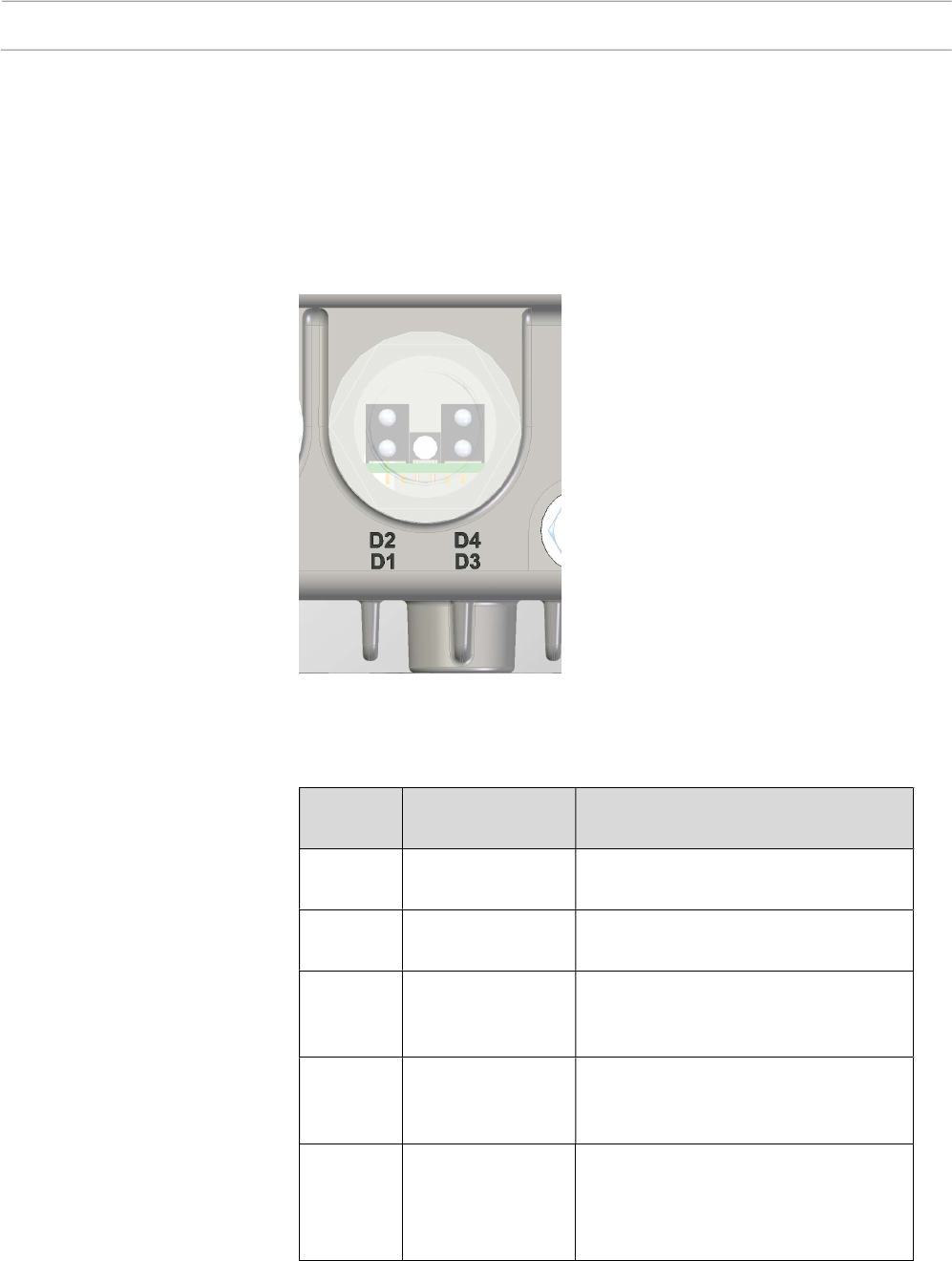
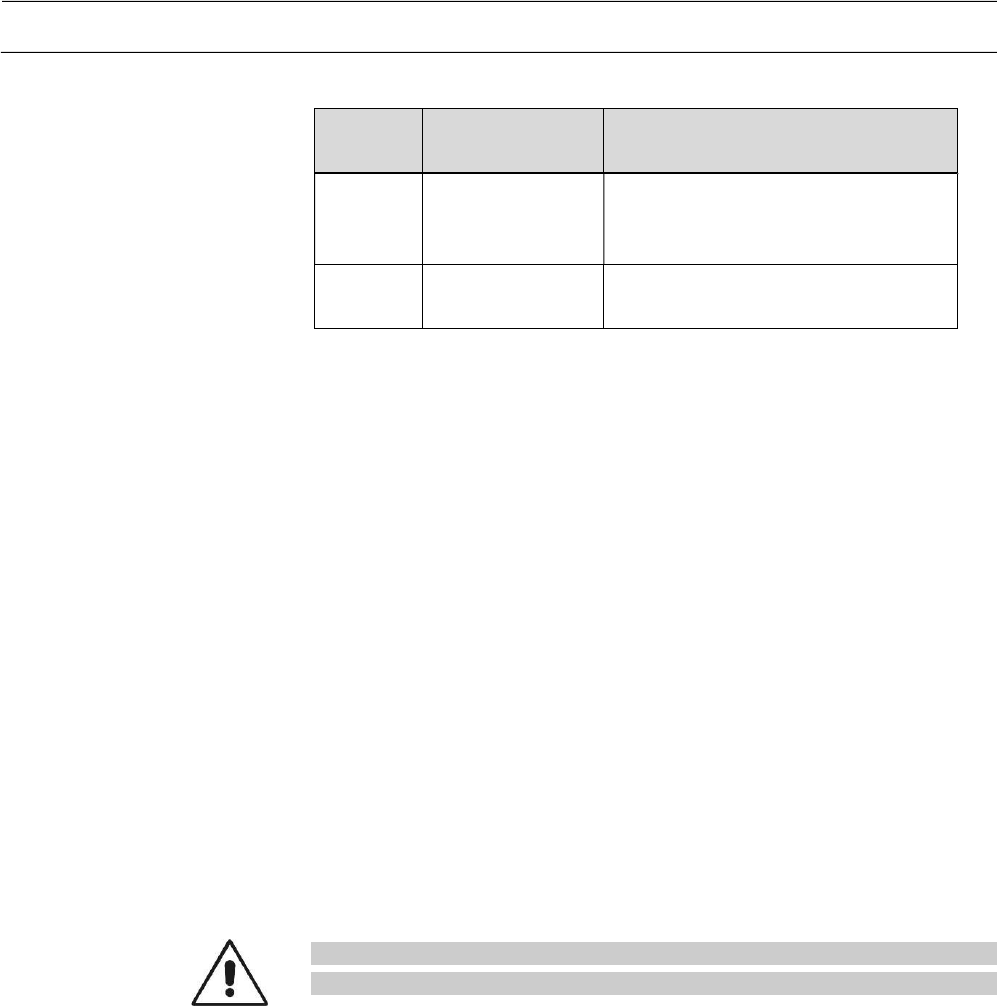
Four status LEDs are provided on the bottom side of the device which indicate
status information of the RIS-9160. The Led D2 “Power” provides off/green,
each other Led provides the three colors green, amber, red.
Figure 4 Auxiliary antenna ports
RIS
-
9160
PoE / Data interface
PoE/LAN data cable
Status LEDs
Auxiliary
Antenna Port 1
GNSS
Technical Manual | Roadside ITS Station RIS-9160-xx0x Page 17 of 36
47000001566-THb-02
D1 General Status
D2 Power
D3 Application specific indication
D4 Application specific indication
Color Status Description
Off No operation Power off
Green Operation ok Device is fully operational.
Green
blinking
Start Device is doing a start, full operation
is not established yet in this state.
Amber SW install Software installation is in progress.
Full operation not established.
Red Fault Device is in a faulty state, operation is
limited or not provided depending on
the kind of fault.
Figure 5
Position of the Status
LED
s
Table 3
D1
–
General Status LED
Page 18 of 36 Technical Manual | Roadside ITS Station RIS-9160-xx0x
47000001566-THb-02
Color Status Description
Off No power Internal power supply is not ok, power
off.
green Power ok Internal power supply is ok.
Note: The indications of D3 and D4 are described in the appropriate software
installation manuals.
The RIS-9160 is equipped with two antenna ports for 5.9GHz
communication, so external antennas can be applied.
“5.9GHz Antenna port 1” is internally connected to the 5.9 Radio 1, port 1.
“5.9GHz Antenna port 2” is internally connected to the 5.9 Radio 1, port 2
The RIS-9160 is equipped with an internal GNSS receiver. An antenna port
for receiving of position and time information is located on the top side of the
device. An external GNSS antenna can directly be applied.
“Auxiliary Antenna Port 1” is used as GNSS antenna port.
If an antenna port is not used it is mandatory to secure the connector with its
appropriate closure, see chapter .
Caution: Ensure that each antenna port is protected in the correct way
whenever changing the usage of a RIS-9160
Table 4
D2
–
Power LED
5.9 Antenna Ports
GNSS Antenna Port
Antenna Port Protection

Technical Manual | Roadside ITS Station RIS-9160-xx0x Page 19 of 36
47000001566-THb-02
Product versions
Available versions of the product family RIS-9160-xA0x 34034340xxx:
Part No. Device name
Additional device name
Description
34034340000 RIS-9160-1A0M
K25104P000000000000
Roadside unit with PoE+
supply, one 5.9GHz radio unit
with dual channel capability,
GNSS interface
Mounting plate: “M”.
CPU: INTEL-ATOM E3825
1,33GHz, 1GB RAM ECC,
4GB eMMC
mSATA SSD: none
µSD memory card: none
34034340001 RIS-9160-1A00
K25104P000000000000
Roadside unit with PoE+
supply, one 5.9GHz radio unit
with dual channel capability,
GNSS interface.
mounting plate: none.
CPU: INTEL-ATOM E3825
1,33GHz, 1GB RAM ECC,
4GB eMMC
mSATA SSD: none
µSD memory card: none
34034340002 RIS-9160-1A0W
K25104P000000000000
Roadside unit with PoE+
supply, one 5.9GHz radio unit
with dual channel capability,
GNSS interface.
Mounting plate “W”.
CPU: INTEL-ATOM E3825
1,33GHz, 1GB RAM ECC,
4GB eMMC
mSATA SSD : none
µSD memory card: none
Table
5
RIS
-
9160
d
evice v
ersion
s
Page 20 of 36 Technical Manual | Roadside ITS Station RIS-9160-xx0x
47000001566-THb-02
Installation
The described mounting applies to RIS-9160 specified in this documentation.
Warning: Installation of the RIS-9160 product must be performed by
trained Kapsch approved staff.
Mounting
In general the following rules apply:
The omni-directional 5.9GHz antenna should point against the road
(ground).
Typical installation height for RIS-9160 is 6 - 8 meters.
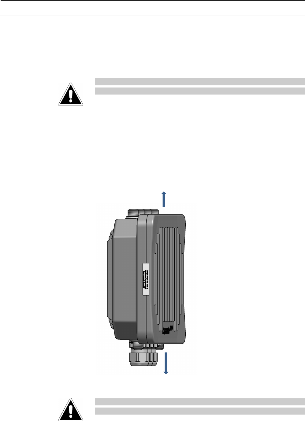
Cable outlet LAN heading oriented downwards.
Warning: When mounting the device to a bridge, a gantry or a wall the
appropriate safety regulations must be followed.
Top
Bottom
Technical Manual | Roadside ITS Station RIS-9160-xx0x Page 21 of 36
47000001566-THb-02
Device without a mounting plate
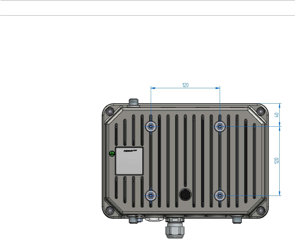
The bare RIS-9160-xxx0 variants like part number 34034340001 are delivered
without a mounting plate but provide four M6-screws on the rear side for
mounting.
Figure 6 RIS-9160 with
out a
mounting
plate
Page 22 of 36 Technical Manual | Roadside ITS Station RIS-9160-xx0x
47000001566-THb-02
Device with mounting plate “M”
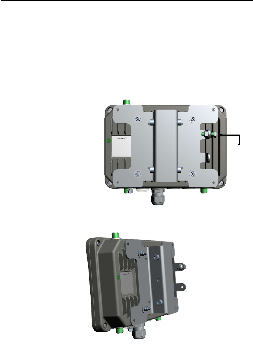
The variants RIS-9160-xxxM like part number 34034340000 are already
equipped with a mounting plate. The mounting plate enables mounting into
the mounting bracket 34017690200 without tools (see chapter “Mounting
Bracket for RIS-9160”). It provides an additional connection of the Frame
ground and also the possibility to mount a sunshield on the outer four drill
holes.
Figure 7
RIS-9160 with mounting plate “M”
–
rear view
Figure 8 RIS-9160 with mounting
plate
“M”
–
side view
Frame Ground Point
Technical Manual | Roadside ITS Station RIS-9160-xx0x Page 23 of 36
47000001566-THb-02
Device with mounting adapter “W”
The variants RIS-9160-xxxW like part number 340340002 are already
equipped with the mounting adapter “W” on the rear side.
Figure 9 RIS-9160
with Mounting
adapter „
W”
Page 24 of 36 Technical Manual | Roadside ITS Station RIS-9160-xx0x
47000001566-THb-02
Electrical Installation
Remark: The cables must be protected against mechanical damage.
Optimal protection offers a protective cable guard. Cables must be fixed
with cable strap in such a way that the maximum protection against
mechanical damage is provided.
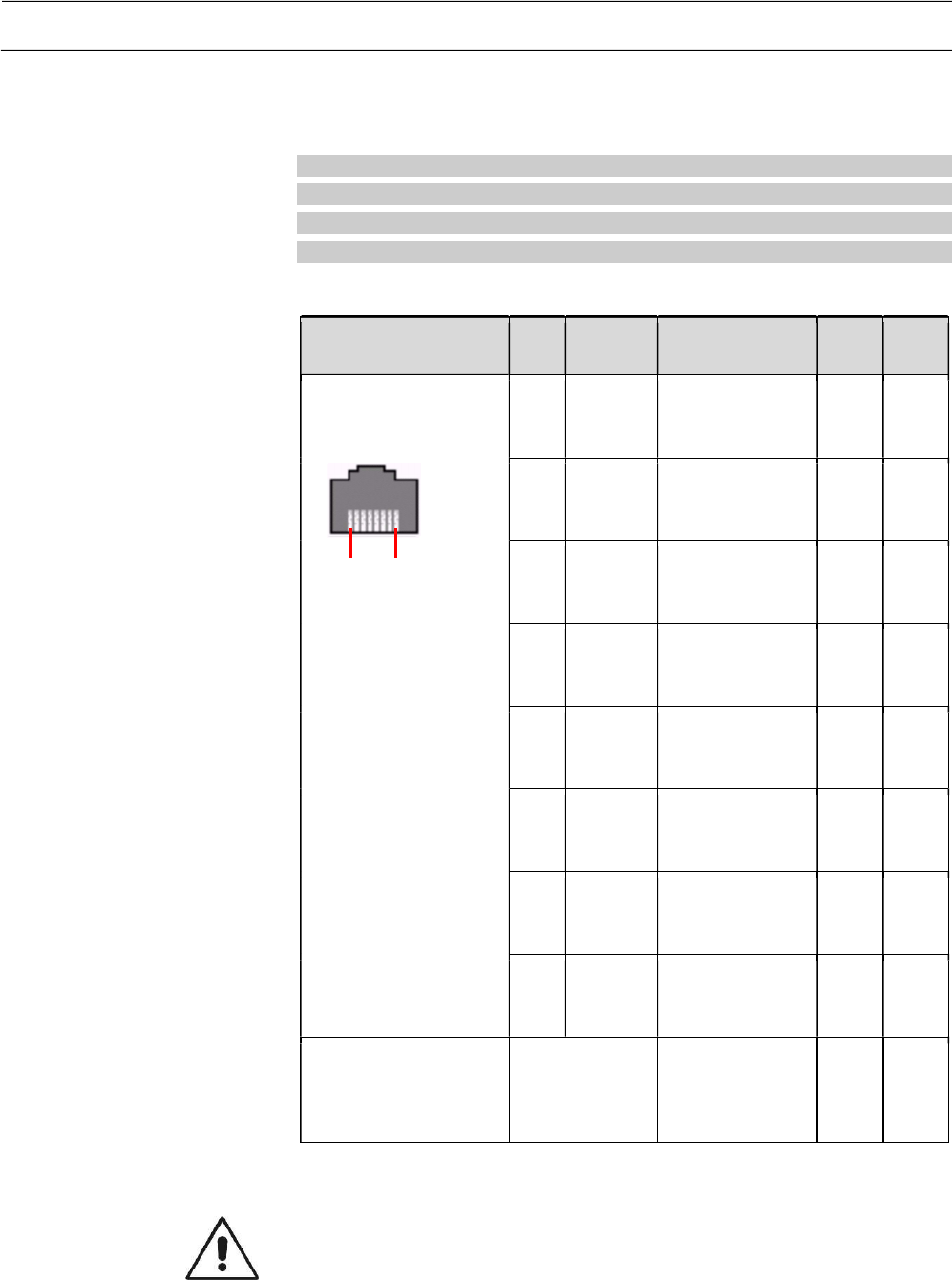
LAN/PoE System-Connector
Connector Pin Signal Description ALT
A
ALT
B
RJ45 8-pin
Socket (female)
18
1 D1+ Data pair 1
, plus
pole,
bidirectional
V+
2 D1- Data pair 1,
minus pole,
bidirectional
V+
3 D2+ Data pair 2
, plus
pole,
bidirectional
V-
4 D3+ Data pair 3
, plus
pole,
bidirectional
V+
5 D3- Data pair 3,
minus pole,
bidirectional
V+
6 D2- Data pair 2,
minus pole,
bidirectional
V-
7 D4+ Data pair 4
, plus
pole,
bidirectional
V-
8 D4- Data pair 4,
minus pole,
bidirectional
V-
Metalized
housing
Internally AC
coupled to
FGND using a
100pF capacitor
V+/- positive/negative pole of the PoE DC power input, Dx+/- Data line
Caution: The earthing of the cable shield must be established on the feed
side because there is internally NO low resistant DC connection provided
between the connected cable shield and the Frame Ground of the device.
Ethernet PoE IEEE 802.3-2012 Phantom power alternative A or B are
supported for 100/100/1000 Base-T
Recommendation for
Cabling
Table 6
LAN/PoE connector signals
Technical Manual | Roadside ITS Station RIS-9160-xx0x Page 25 of 36
47000001566-THb-02
System cable connection
The system connector concept of the RIS-9160 ensures a stable and
waterproof connection of the system cables with the device. To ensure this
the cables have to be connected as described in this section.
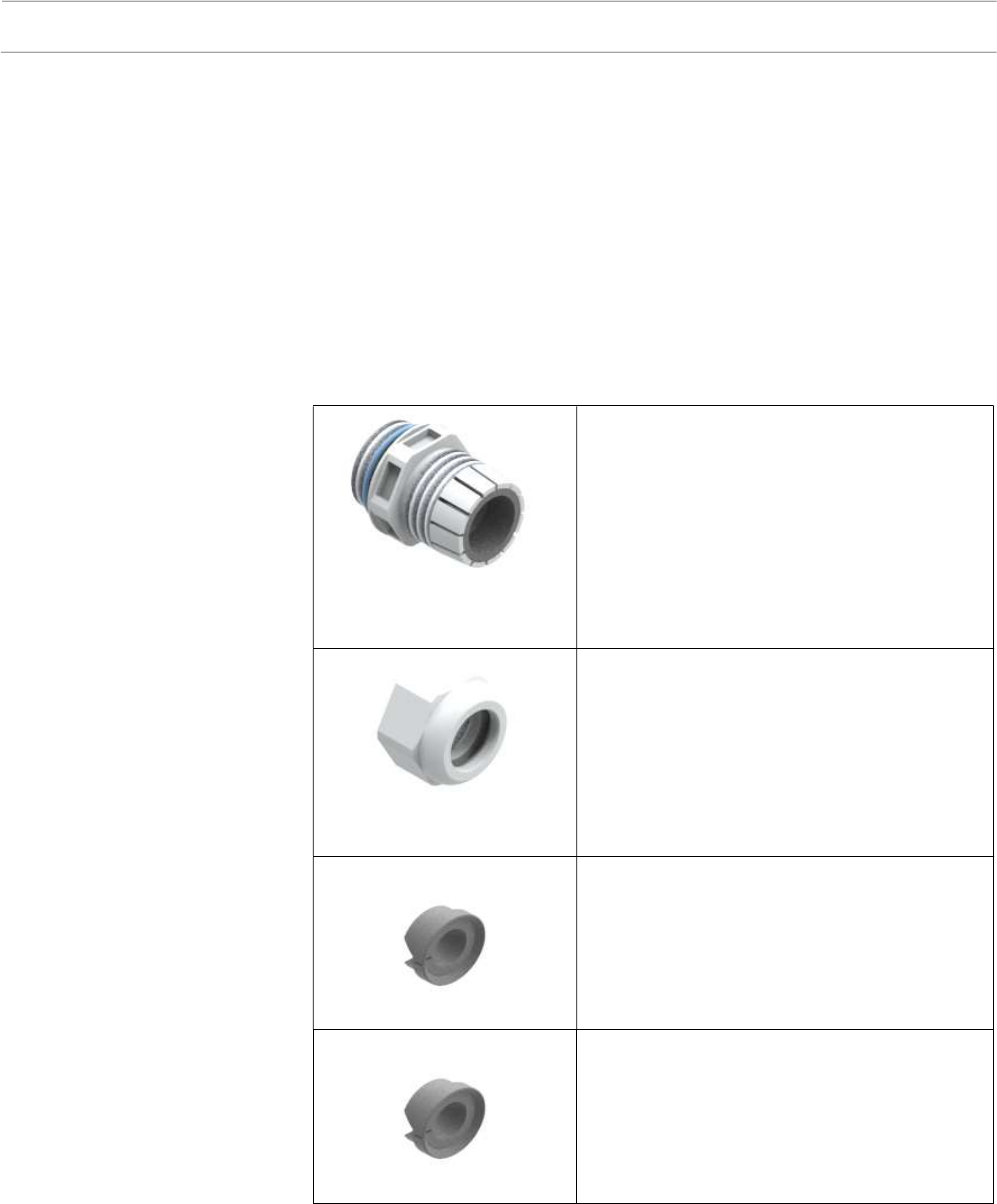
1. Check if the Connector assembly parts according Table 7 are complete.
Cable gland – fitting with original gasket
inserted
Material: Polyamide
Key width SW: 29mm
Inner Diameter: max. 17mm
Cable gland - cap nut
Material: Polyamide
Key width SW: 29mm
Inner Diameter: max. 17mm
Rubber gasket size A
Material: EPDM
Cable Diameter: STP 7,0-9,0 mm
Rubber gasket size B
Material: EPDM
Cable Diameter: STP 4,0-6,5 mm
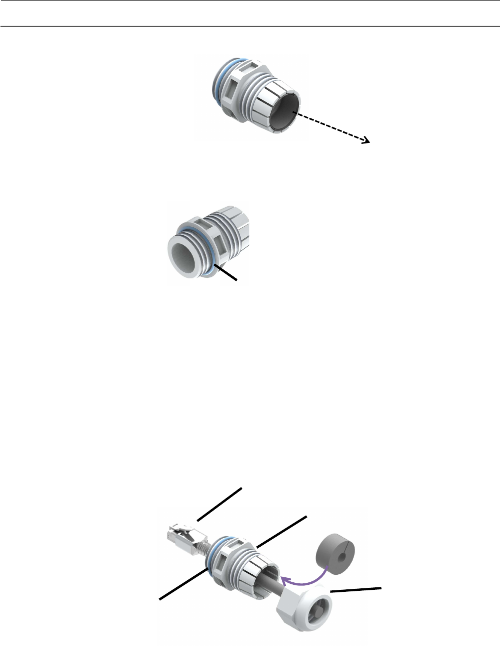
2. Remove the original gasket out of the cable gland fitting according Figure
10.
Preparation
Table 7 Connector assembly
parts
Page 26 of 36 Technical Manual | Roadside ITS Station RIS-9160-xx0x
47000001566-THb-02
3. Check if the Sealing is placed correctly on the fitting according Figure 11
4. Prepare the correct size A or size B of the rubber gasket depending on
the cable diameter.
5. Push the cable carefully through the cap nut and cable gland fitting
according Figure 12. Ensure that the locking mechanism remains intact.
6. Attach the appropriate rubber gasket size A or size B depending on the
cable diameter according Figure 12 so that the profiled side of the gasket
is oriented towards the fitting !
Figure
10
Remove original gasket
Figure
11
P
osition of the sealing
Figure 12 Cable
Connection
Mounting Details
Cable gland-fitting
Cap nut
RJ45 connector with locking mechanism
Rubber gasket
Sealing
Sealing
Remove the original
gasket
Technical Manual | Roadside ITS Station RIS-9160-xx0x Page 27 of 36
47000001566-THb-02
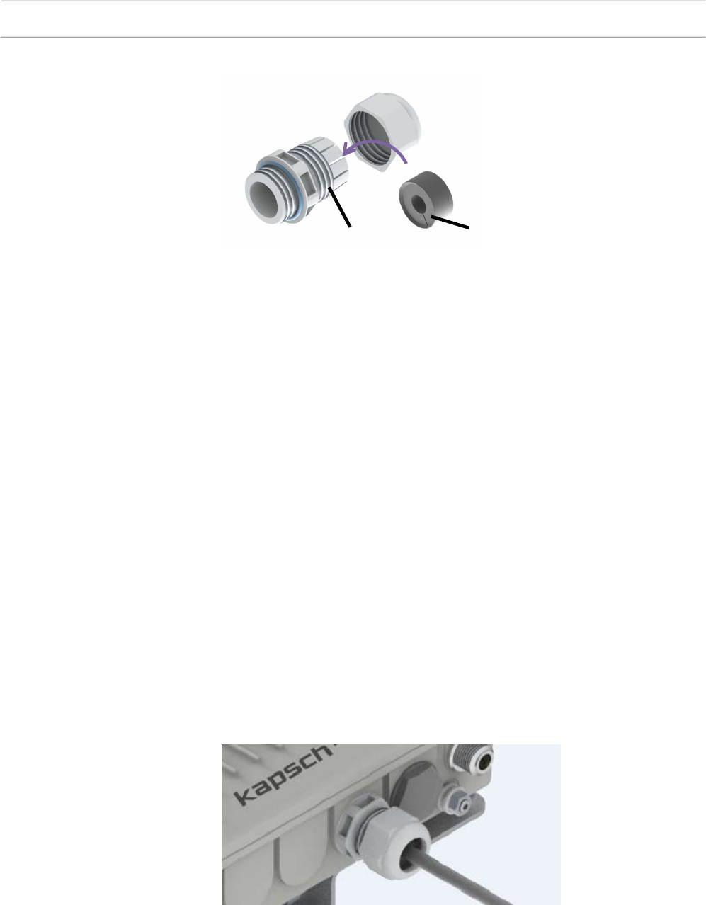
7. Check the correct direction of the rubber gasket which is also shown in
Figure 13 to ensure waterproofness of the connection !
8. Connect the RJ45 connector to the system connector of the RIS-9160
and ensure that the locking mechanism of the connector is fixed.
9. Attach the cable gland - fitting carefully to the threaded whole in the RIS-
9160, ensure that the thread fits smoothly and fasten the fitting with a
torque of 10 Nm.
10. Slide the rubber gasket into the slot of the fitting.
11. Move the cap-nut across the fitting.
12. Fasten the cap-nut to the fitting with a torque of 4 Nm.
Attention: Overpowering will irreversibly destroy the Polyamide thread!
Too less torque will not ensure rated IP Class.
Figure 13 Direction of the Rubber
Gasket
Figure 14
RIS-9160 with connected system
cable
Rubber gasket
Cable gland-fitting

Page 28 of 36 Technical Manual | Roadside ITS Station RIS-9160-xx0x
47000001566-THb-02
Product Specifications
Dimensions [LxWxH]
without bracket
11.5 in x 7.9 in x 3.07 in
(290mm x 200mm x 78mm)
Weight without bracket <6.6 pounds (~3 kg)
Material of housing Aluminum alloy die casting
PoE/LAN system interface
Rated Input Voltage PoE Nom. 48V DC (IEEE 802.3at)
Input Voltage Range Min: 36V DC
Max: 57V DC
POE device classification
Type 2, PoE+, max. 25.5 W over two pairs
Supported POE power
modes:
Mode A (via pins 1-2 / 3-6)
Mode B (via pins 4-5 / 7-8)
4 pair mode
Galvanic insulation 2250V AC for 1 minute
Protection Internal Surge protection
LAN Physical Interface 10/100/1000 BASE – T
Power consumption
RIS-9160-1A0x
34034340xxx,
≤ 14W
Platform Specification
Processor 1,33 GHz, 64 Bit, INTEL ATOM E3825 dual-core
Basic Memory config. 1GB RAM ECC / 4GB eMMC SLC
Optional memory config Up to 8GB RAM ECC, up to 64 GB eMMC
SLC/MLC
Operating System Linux
Optional SSD: mSATA-SSD, iSLC, 6GB/s, 8-256 GB
Optional µSD card: Micro SD up to 128GB
5.9 Radio 1
Frequency range 5.860GHz - 5.920GHz
Channels 172,174, 176,178,180,182,184
Channel Bandwidth 10MHz
Data Rates 6MBit/s
Mechanical Characteristics
Electrical Characteristics
and Conditions
RF Interfaces

Technical Manual | Roadside ITS Station RIS-9160-xx0x Page 29 of 36
47000001566-THb-02
Antenna Connector Type N female
Output power 20dBm (CFR 47 Part 90 Class C)
Output power
Adjustment range
0dBm .. +20dBm in 1dB steps
Receiver Sensitivity -92dBm @ 6Mbps (typ.)
ACR/NACR Enhanced
GNNS Interface
System support Multi GNSS
Antenna Connector Type N female
Antenna Type GPS Antenna, passive or active
supply 3,3V for active antenna
LED Interface
Indications 1 x green LED (Power indication)
1 x 3-color LED (Status indication)
2 x 3-color LEDs (SW defined)
Environmental Conditions
Temperature (operation) -40°C ...+74°C
-40 F … +165,2 F
This temperature range does not consider increase of temperature due to
exposure to solar irradiation. It’s mandatory to use the optional sun cover if
the case temperature exceeds this limit due to solar irradiation.
Temperature (storage) -40°C ...+85°C
-40F … 185F
IEC protection rating NEMA 4X
IP67
Oscillation sinus
(operation)
EN60068-2-6 Fc (2008-12)
1-9Hz 3,5mm
10-200Hz, 10 m/s2
Oscillation random
(operation)
EN60068-2-64 Fc (2008-12)
100-200Hz / -7dB/octave
200-2000Hz / 1m2/s3
10-100Hz / 5m2/s3
Shock
(operation)
EN60068-2-27 Ea(2010-04)
150m/s² / 6ms
MTBF 100.000h according to BELLCORE TR-TSY-
000332
Environmental Conditions

Page 30 of 36 Technical Manual | Roadside ITS Station RIS-9160-xx0x
47000001566-THb-02
FCC-ID: XZU9160
(FCC will be available after conclusion of certification / listing)
Product Marking
Technical Manual | Roadside ITS Station RIS-9160-xx0x Page 31 of 36
47000001566-THb-02
Mechanical Dimensions
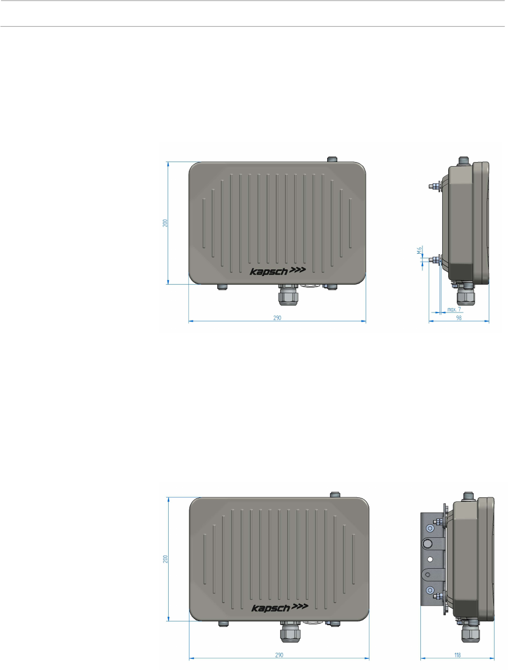
All dimensions are given in mm.
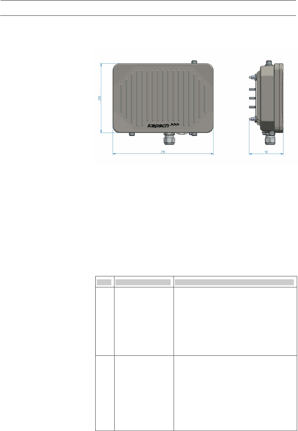
Figure 15 shows the dimensions of the RIS-9160-xxx0 device versions like
part nr. 34034340001 without mounting plate where four M6 metrical screws
are provided for mounting on the rearside of the device. Those screws are
already premounted. in the factory.
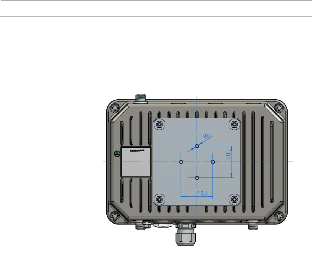
Figure 16 shows the dimensions of the RIS-9160-xxxM device versions with
mounting plate “M” like part nr. 34034340000.
Figure 15 Dimensions of RIS-
9160
without mounting plate
Figure 16 Dimensions of RIS-9160
with
mounting plate
”
M
”
Page 32 of 36 Technical Manual | Roadside ITS Station RIS-9160-xx0x
47000001566-THb-02
Figure 17 shows the dimensions of the RIS-9160-xxxW device versions like
part nr. 34034340002 with mounting adapter “W”.
Conformity
Standards
Ref. Standard Description
[1] IEEE 802.11™2012 IEEE Standard for
Information technology—
Telecommunications and information
exchange between systems—
Local and metropolitan area networks—
Specific requirements
Part 11: Wireless LAN Medium Access Control
(MAC) and Physical Layer (PHY)
Specifications
[2] IEEE 802.11™p IEEE Standard for
Information technology—
Telecommunications and information
exchange between systems—
Local and metropolitan area networks—
Specific requirements Part 11: Wireless LAN
Medium Access Control (MAC) and Physical
Layer (PHY) Specifications
Amendment 7: Wireless Access in Vehicular
Environments
Figure 17 Dimensions of RIS-
9160
with mounting adapter
“W”
Table 8
Standards

Technical Manual | Roadside ITS Station RIS-9160-xx0x Page 33 of 36
47000001566-THb-02
Ref. Standard Description
[3] IEEE 1609.4™ 2016 Draft Standard for Wireless Access in
Vehicular Environments (WAVE) –
Multi-channel Operation
[4] IEEE 1609.3™ 2016 Draft Standard for Wireless Access in
Vehicular Environments (WAVE) –
Networking Services
[5] IEEE 1609.12™ 2016
Standard for Wireless Access in Vehicular
Environments (WAVE) – Identifier Allocations
[6] 47 CFR Part 2 Code of Federal Regulations, Title 47, Part 2
(47 CRF 2)
Part 2 – Frequency allocations and radio
treaty matters; General rules and regulations
[7] 47 CFR Part 15 Code of Federal Regulations, Title 47, Part 15
(47 CFR 15)
Part 15 – Radio Frequency Devices
[9] 47 CFR Part 90 Code of Federal Regulations, Title 47, Part 90
(47 CRF 90)
Part 90 – Private Land Mobile Services
[10] NEMA Standards
(NEMA 250-2008)
NEMA Standard for Enclosures for Electrical
Equipment
[11] IEC 62368-1 Audio/video, information and communication
technology equipment – Part 1: Safety
requirements
[11a] IEC 60950-22 International Electrotechnical Com-mission –
Safety of Information Technology Equipment-
Part 22: Equipment installed outdoors
[12] EN 302 571 V2.1.1
(2017-02)
Intelligent Transport Systems (ITS);
Radiocommunications equipment operating in
the 5 855 MHz to 5 925 MHz frequency band;
Harmonised Standard covering the essential
requirements of article 3.2 of Directive
2014/53/EU
[13] EN 301 489-1 V2.2.0 ElectroMagnetic Compatibility (EMC)
standard for radio equipment and services;
Part 1: Common technical requirements;
Harmonised Standard covering the essential
requirements of article 3.1(b) of Directive
2014/53/EU and the essential requirements of
article 6 of Directive 2014/30/EU
[14] EN 301 489-3 V2.1.1 ElectroMagnetic Compatibility (EMC)
standard for radio equipment and services;
Part 3: Specific conditions for Short-Range
Devices (SRD) operating on frequencies
between 9 kHz and 246 GHz;
Harmonised standard covering the essential
requirements of article 3.1(b) of Directive
2014/53/EU

Page 34 of 36 Technical Manual | Roadside ITS Station RIS-9160-xx0x
47000001566-THb-02
Ref. Standard Description
[15] EN 62 311: 2008 Assessment of electronic and electrical
equipment related to human exposure
restrictions for electromagnetic fields (0 Hz -
300 GHz)
Statement of Conformity
The following information applies to the product listed in Table 1.
Hereby, Kapsch TrafficCom AG declares that the products listed in this
document are in compliance with the essential requirements and all other
relevant provisions of Directive 2014/53/EU.
The Declaration of Conformity is available for download from
https://www.kapsch.net/ktc/Portfolio/Products/RF-Field-Products/5-9-GHz-
WAVE-DSRC-Transceivers
For further information please contact us.
Kapsch TrafficCom AGAm Europlatz 2
A-1120 Vienna
Tel.: +43 (0)50 811 0
Email: ktc.info@kapsch.net
Information on Conformity
of Products
Declaration
Address
Technical Manual | Roadside ITS Station RIS-9160-xx0x Page 35 of 36
47000001566-THb-02
Optional Equipment
Mounting Bracket for RIS-9160
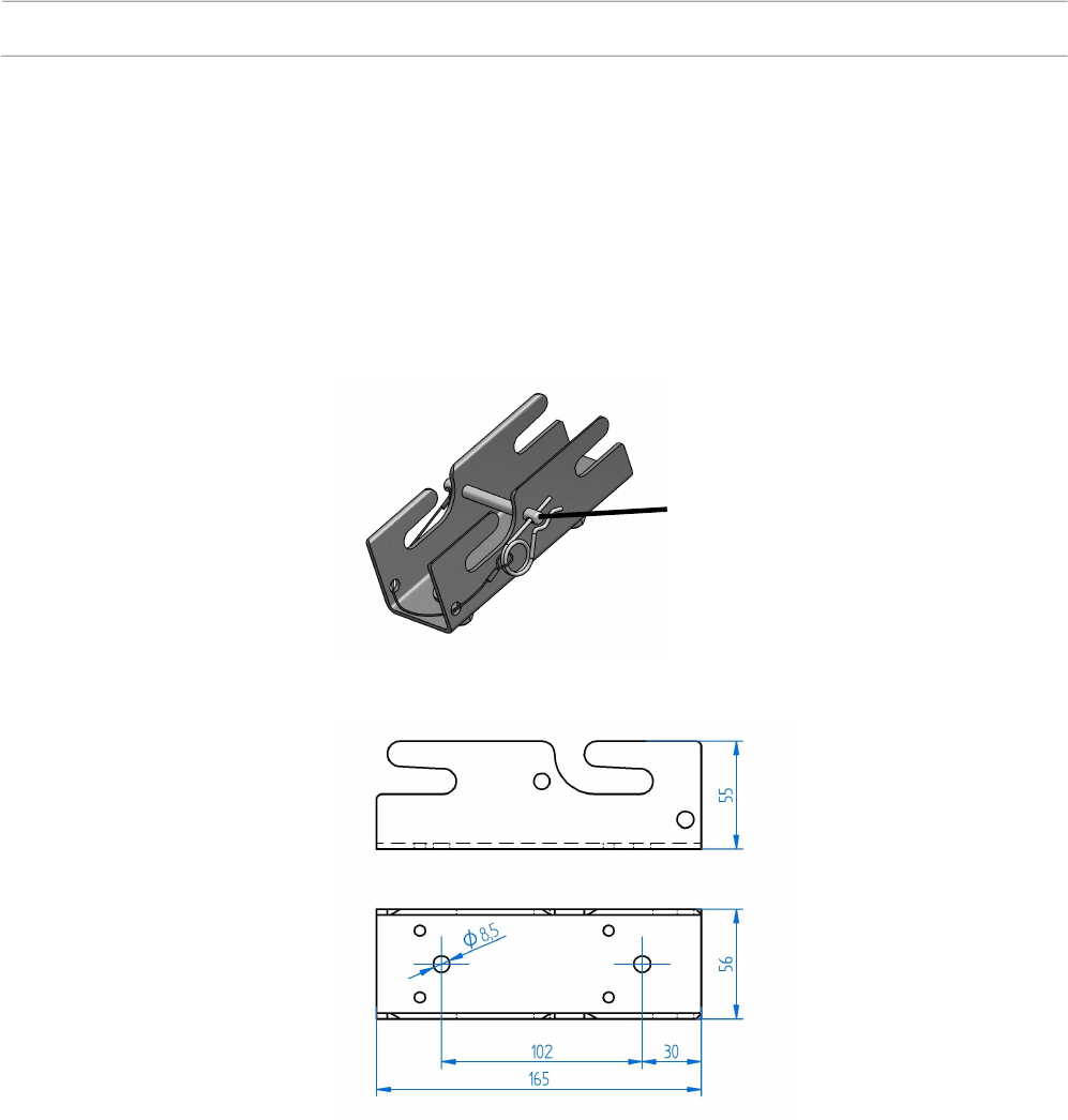
The counterpart of the mounting plate “M” is the mounting bracket with
locking, Kapsch part number 34017690200.
To protect the device from unintentionally slipping out of the mounting bracket
it is secured with the Safety Wire. The Safety Wire itself is protected against
loss or drop-down as it is attached to the bracket through additionally
dedicated security holes. Material: Stainless steel
Note: The outline of the safety wire can slightly differ from the shown one in
Figure 18.
Figure 18
M
ounting
B
racket with
safety wire
Figure 19
Dimensions and
drilling plan of the
Mounting Bracket
Safety wire
Page 36 of 36 Technical Manual | Roadside ITS Station RIS-9160-xx0x
47000001566-THb-02
Protection caps and termination plugs
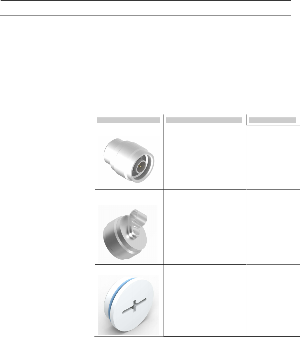
The protection caps and the RF terminations are delivered depending on
customer configuration and demand along with each RIS-9160 or can be
ordered separately.
Termination type Description Kapsch Part No.
RF termination (50Ohm)
RF termination plug, N male,
50R, 2W.
Note: IP66 protection class
only !
76000046410
N connector protection
cap
N-Connector protection cap,
no RF termination, 130 Ncm
rated torque.
76000066660
M25x1,5 cap and sealing
Cap
Sealing
Note: The specified protection
class of IP67 is only ensured
when both cab and sealing
are mounted !
76000066560
76000078180
Table 9
Protection caps and termination
plugs