Kapsch Trafficcom 9450 Localisation Transceiver User Manual Technical Manual
Kapsch Trafficcom AG Localisation Transceiver Technical Manual
User Manual

Kapsch TrafficCom AG
Technical Manual
WAVE Transceiver with precise
localization capability MTX-9450 and
TRX-9450
This device is based on the IEEE WAVE Standards
1000005502-THb-02

1000005502-THb-02
Order number: 1000005502
Document type THb
Document issue 02
Document status released
Date of issue 2010-03-23
Valid from
Author: Manfred Batko
Assessor: Robert Povolny
Release: Werner Lackner
Disclaimer and Limitation of Liability
The products described in this manual are provided “as is” and without any warranties of any
kind, either express or implied. Kapsch TrafficCom disclaims all warranties, express or implied,
including, but not limited to, warranties of title, legality or non-infringement or misappropriation
of any intellectual property rights of third parties or implied warranties of merchantability or
fitness for a particular purpose. Under no circumstances will Kapsch TrafficCom (including its
affiliates, licensors, contractors, suppliers, assignees, subsidiaries, and the respective officers,
directors, employees, shareholders, agents and representatives of each of them) be liable for any
expenses, fees, claims, damages or losses in any way relating to or arising out of the products
described in this manual. Applicable law may not allow certain warranty exclusions, so one or
more of the above disclaimers may not apply to you.
Copyright Kapsch TrafficCom AG 2010
Duplication as well as utilization of contents of this documentation are illegal without our explicit consent.

Page 3 of 26
1000005502-THb-02
Table of Contents
Page
Information about this document 5
Text conventions ............................................................................................. 5
Important text elements ................................................................................... 5
Abbreviations ................................................................................................... 6
Warning to users in the United States 7
Regulatory Information 8
Safety Instructions 9
Maintenance Instructions 9
Inspection Instructions 9
Environmental Information 10
Visual Inspection 10
Installation Instructions 10
General Information 11
Definitions ...................................................................................................... 11
System Overview 12
Performance Overview .................................................................................. 12
System Architecture ...................................................................................... 13
Modular Architecture .............................................................................. 13
Compact Architecture ............................................................................. 15
Installation 17
Mounting position and height ........................................................................ 17
Mounting plate for MTX-9450 and TRX-9450 ............................................... 17
Bracket for MTX-9450 and TRX-9450........................................................... 18
Electrical Installation...................................................................................... 19
Connection Cable (Ethernet + Power Supply) ....................................... 19
Signals at connector “IN” of MTX-9450/TRX-9450 ................................ 20
Line Connection Cable (Ethernet + Power Supply) ............................... 21
Signals at connector “OUT” of MTX-9450.............................................. 22
Product Specifications 23
Transceivers MTX-9450 and TRX-9450 ....................................................... 23
Conformity 25
Standards ...................................................................................................... 25

Page 4 of 26 Technical Manual | WAVE Transceiver with precise localization capability MTX-9450 and TRX-9450
1000005502-THb-02
Table of Figures
Page
Figure 1 WAVE Localization Transceiver..................................................... 12
Figure 2 System variant “Modular Architecture“ ......................................... 13
Figure 3 System variant “Line application with Master-Transceiver“ ........... 15
Figure 4 Mounting plate for MTX-9450 and TRX-9450 ................................ 17
Figure 5 Bracket for MTX-9450 and TRX-9450 ........................................... 18
Figure 6 Connection Cable (Ethernet + Power Supply) .............................. 19
Figure 7 Connector pin assignment Connection Cable (Ethernet + Power
Supply) ......................................................................................... 19
Figure 8 Line Connection Cable (Ethernet + Power Supply) ...................... 21
Figure 9 Connector pin assignment Line Connection Cable (Ethernet +
Power Supply) .............................................................................. 21
List of Tables
Page
Table 1 Text formats and their meaning ........................................................ 5
Table 2 Transceivers for the system variant “Modular Architecture” ........... 13
Table 3 Available TCM and TIM modules .................................................... 14
Table 4 Available PPS-RS422-MUX modules ............................................ 14
Table 5 Recommended power supplies ....................................................... 14
Table 6 Available Transceiver Controllers TRC-1040-IPC .......................... 14
Table 7 Localization Transceivers for the system variant “Line application
with Master-Transceiver” .............................................................. 15
Table 8 Available TCM and TIM modules .................................................... 16
Table 9 Available lengths of Connection Cable ........................................... 19
Table 10 Signals at connector “IN” of MTX-9450/TRX-9450 ....................... 20
Table 11 Available cable lengths Line Connection Cable ............................ 21
Table 12 Signals at connector “OUT” of MTX-9450 ..................................... 22
Table 13 Standards ...................................................................................... 25
Technical Manual | WAVE Transceiver with precise localization capability MTX-9450 and TRX-9450 Page 5 of 26
1000005502-THb-02
Information about this document
This document is addressed to qualified staff only.
Qualified staff have the appropriate knowledge in the scope of electrical
engineering and have been instructed and authorized by Kapsch.
This Technical Manual shall be carefully read before installation.
Text conventions
Visual aids and standard text formats in this manual help the reader to locate
and identify information easily.
Typographical formats:
Style Used for
bold Accentuations
italics Labelling and cross-references
CAPITAL LETTERS Acronyms
Important text elements
This manual contains specific Caution and Warning statements. These shall
be interpreted as follows:
Attention: This warning indicates that the device may be affected by
Electrostatic Discharge. Appropriate precautions must be made to avoid
damage to the device.
Caution: A caution sign indicates concerns about a procedure which
may lead to equipment damage or violation of regulatory requirements.
Warning: indicates a potential danger that requires correct procedures
or practices in order to prevent injury to humans or damage to the
equipment.
Audience
Preparations
Table 1
Text formats and their meaning
Attention
Caution
Warning

Page 6 of 26 Technical Manual | WAVE Transceiver with precise localization capability MTX-9450 and TRX-9450
1000005502-THb-02
Abbreviations
DL Downlink direction (Information from TRX)
DSRC Dedicated Short Range Communication
EIRP Equivalent Isotropic Radiated Power
MLFF Multi Lane Free Flow
MTX Master Transceiver
OBU On Board Unit
RSU Roadside Unit
TCM Transceiver Connection Module
TIM Transceiver Interface Module
TRC Transceiver Controller
TRP Transponder Unit
TRX Transceiver
UL Uplink direction (Information to TRX)

Technical Manual | WAVE Transceiver with precise localization capability MTX-9450 and TRX-9450 Page 7 of 26
1000005502-THb-02
Warning to users in the United
States
The hardware referred to in this document allows selection of frequency
bands and transmit power levels that may not comply with the regulatory
body that governs spectrum policy where the hardware is being used.
The operator is required apply for and obtain a 47 CFR Part 90 geographic
area license from the FCC that has specified eligibility requirements to
operate this device in the United States (47 CFR Part 90.375). See product
label for FCC ID number.
Individual devices have to be registered. Such licenses serve as a
prerequisite to registering individual devices located within the licensed
geographic area. Licensees must register each installation in the Universal
Licensing System (ULS) before operating an Roadside Unit (RSU).
For further information about DSRC regulations in the US please refer to
http://wireless.fcc.gov/services/index.htm?job=service_home&id=dedicated_src
Local Regulations
License Required

Page 8 of 26 Technical Manual | WAVE Transceiver with precise localization capability MTX-9450 and TRX-9450
1000005502-THb-02
Regulatory Information
This device complies with Part 15 of the FCC Rules. Operation is subject to
the following two conditions:
1. This device may not cause harmful interference, and
2. this device must accept any interference received, including
interference that may cause undesired operation.
Changes or modifications made to this equipment not expressly approved by
Kapsch may void the FCC authorization to operate this equipment.
Note: This equipment has been tested and found to comply with the
limits for a Class B digital device, pursuant to Part 15 of the FCC Rules.
These limits are designed to provide reasonable protection against
harmful interference in a residential installation. This equipment
generates uses and can radiate radio frequency energy and, if not
installed and used in accordance with the instructions, may cause
harmful interference to radio communications. However, there is no
guarantee that interference will not occur in a particular installation. If
this equipment does cause harmful interference to radio or television
reception, which can be determined by turning the equipment off and
on, the user is encouraged to try to correct the interference by one or
more of the following measures:
• Reorient or relocate the receiving antenna.
• Increase the separation between the equipment and receiver.
• Connect the equipment into an outlet on a circuit different from
that to which the receiver is connected.
• Consult the dealer or an experienced radio/TV technician for help.
This equipment complies with FCC radiation exposure limits set forth for an
uncontrolled environment. This equipment should be installed and operated
with minimum distance of 20 cm (8 inches) between the radiator and a
human body. Failure to do so could result in bodily injury or death.
This transmitter must not be co-located or operating in conjunction with any
other antenna or transmitter.
Notice
Notice
Class B digital device
Radio frequency radiation
exposure Information
Technical Manual | WAVE Transceiver with precise localization capability MTX-9450 and TRX-9450 Page 9 of 26
1000005502-THb-02
Safety Instructions
Caution: The TCM/TIM overvoltage protection module must be used.
Caution: Cables shall not be bent to a smaller radius than specified by
the cable manufacturer. For cables listed in this manual the bent radius
shall be larger than 5 inch (12cm)
Caution: It is necessary to connect the device to ground with a low
impedance connection.
This reminder is provided to call the systems installer's attention to
Section 820.93 of the NFPA 70® National Electrical Code ® 2008
Edition, which provide guidelines for proper grounding and, in
particular, specify that the coaxial cable shield shall be connected to the
grounding system of the building, as close to the point of cable entry as
practical.
Maintenance Instructions
The Localization Transceivers MTX-9450 and TRX-9450 need no regular
electrical maintenance.
Inspection Instructions
Warning: Regular inspection of installed equipment is mandatory and
shall be in accordance with the local safety regulations for equipment
installed on the roadside.
Overvoltage
Protection
Handling of Cables
Grounding
Note to GPS System
Installer

Page 10 of 26 Technical Manual | WAVE Transceiver with precise localization capability MTX-9450 and TRX-9450
1000005502-THb-02
Environmental Information
Your equipment set consists of material that can be recycled by specialized
companies. Please observe the local regulations regarding the disposal of
packaging material and waste electronic equipment.
The transceiver is protected against environmental influences by NEMA 4X
enclosure. No additional protection measures are required for roadside open
air installations.
Visual Inspection
Always check the shipment for completeness and possible damage. If the
content is incomplete or damaged, a claim should be filed with the carrier
immediately and contact your local Kapsch office.
Installation Instructions
For information regarding applications for and installation of the products
described in this manual, please see the application notes.
Recycling
Environmental
requirements

Technical Manual | WAVE Transceiver with precise localization capability MTX-9450 and TRX-9450 Page 11 of 26
1000005502-THb-02
General Information
Definitions
The Master transceiver performs communications with an OBU
autonomously. It basically includes the functionality of radio module and
controller software to perform the communication with the OBU. It can be
used as a standalone device or in conjunction with one slave transceiver.
Slave transceivers are able to perform communications with OBUs by the
use of a transceiver controller. The communication is initialized and
controlled by the transceiver controller, and forwarded by the transceiver. In
this application the transceiver acts as a wireless bridge.
Multiple transceivers may be combined in a modular architecture to cover
specific communications areas.
The transceiver controller performs the application by using the slave
transceiver as a wireless network bridge. The transceiver controller further
provides the interface to the host e.g. lane controller, central system.
The size of the communication zone is defined as the space within
communication with another device (e.g., OBU) is reliable. The size of the
communication zone is mostly influenced by the mounting height and
mounting angle of the transceiver, the antenna utilized and the maximum
power level used.
Master Transceiver
(Slave) Transceiver
Transceiver Controller
Communication zones of
the transceivers
Page 12 of 26 Technical Manual | WAVE Transceiver with precise localization capability MTX-9450 and TRX-9450
1000005502-THb-02
System Overview
The 5.9 WAVE Transceiver family with precise localization capability
implemented in roadside systems supports reliable data exchange with
standard compliant Onboard Units (OBUs).
Performance Overview
• WAVE/802.11p compliant DSRC transceiver with precise localization
functionality
• Compatible with WAVE/802.11p compliant OBUs
• Products operate in single - lane- and multi – lane environments
• Weather proof, robust and compact housing
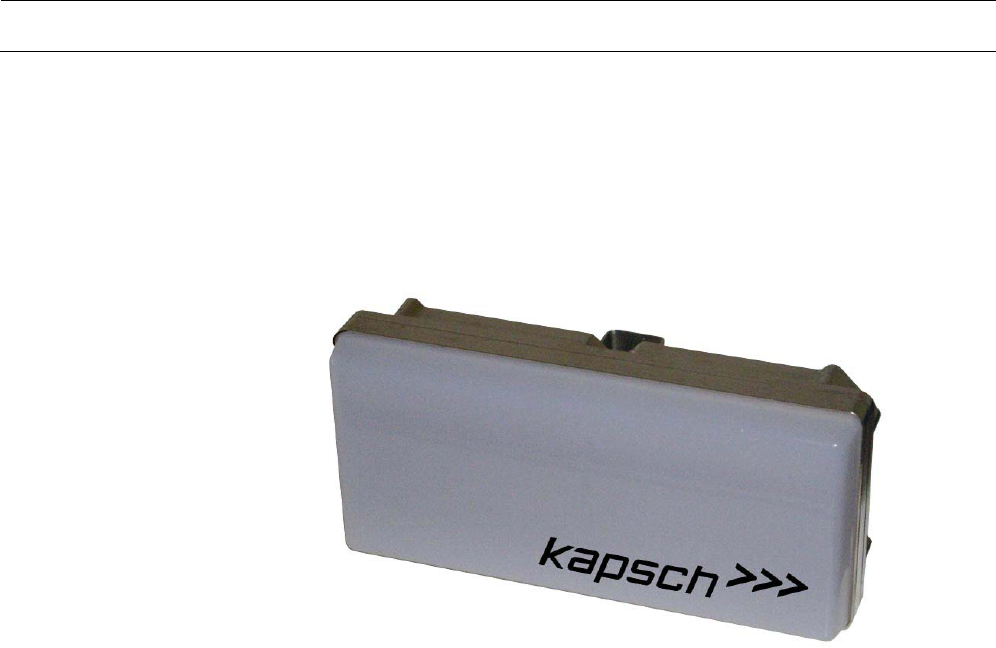
Figure 1
WAVE Localization Transceiver
Technical Manual | WAVE Transceiver with precise localization capability MTX-9450 and TRX-9450 Page 13 of 26
1000005502-THb-02
System Architecture
The 5.9 WAVE Localization Transceiver family supports 2 types of
architectures.
• Modular Architecture (see the following chapter)
• Compact Architecture (see page 15)
Modular Architecture
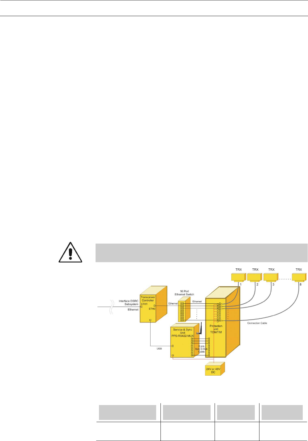
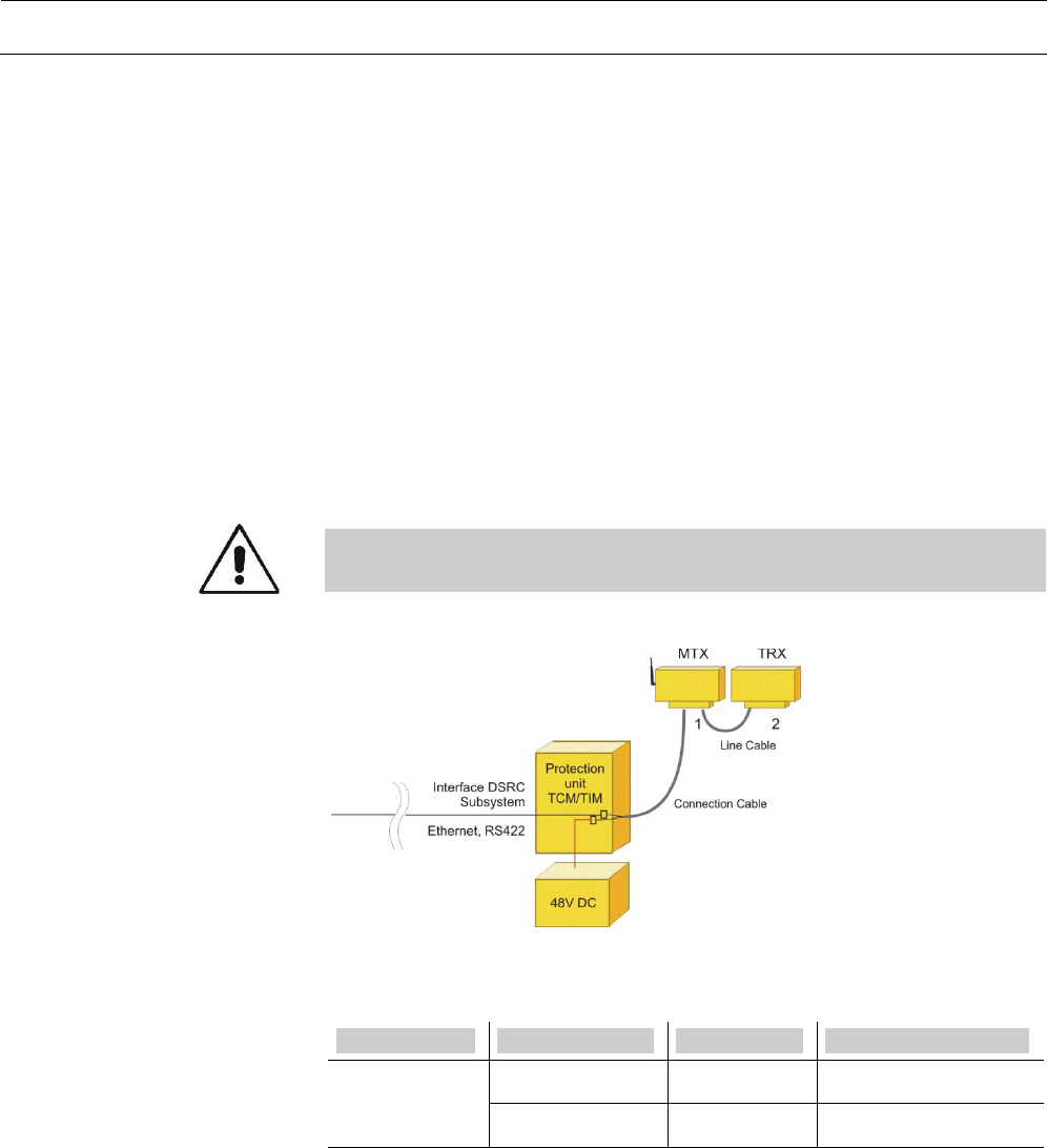
This architecture has the highest flexibility for different system setups. It can
be scaled from 1 up to 8 lanes.
The system consists of 1 transceiver controller and up to 8 transceivers.
• The system interface is based on Ethernet
• The transceivers have to be supplied with an external 24 or 48V DC
power supply unit.
• Each Transceiver is internally protected against surges on data and
power lines
• The PPS-RS422-MUX is used for synchronization and service purposes
of the TRX
Caution: At the roadside cabinet a TCM/TIM over-voltage protection
unit must to be used to protect the controller against surges.
The following types of Transceivers are available for the modular
architecture.
System
Type
Kapsch
Part No.
Description
Modular TRX-9450 34026470000 Slave
Transceiver
Scope
System structure
Figure 2
System variant
“Modular Architecture“
TRX 1 to 8
Table 2
Transceivers for the system
variant “Modular Architecture”

Page 14 of 26 Technical Manual | WAVE Transceiver with precise localization capability MTX-9450 and TRX-9450
1000005502-THb-02
See applications notes.
Max. Length 260feet (80m)
See chapter “Connection Cable (Ethernet + Power Supply)” on page 19.
The transient protection unit consists of the two modules.
Module
Description
Kapsch
Part No.
TCM-0902 Module holder for up to two TIM modules 34019410000
TCM-0904 Module holder for up to four TIM modules 34018320000
TIM-5310* Overvoltage Protection Unit
(48V / 2.5A fuse, type slow blowing)
34026560000
* Quantity: 1 TIM module per transceiver
For more detailed information see the technical manual of the transient
protection unit (Doc. No. 1000002917 or 1000003873).
Module
Description
Kapsch
Part No.
PPS-RS422-MUX-2 Service and Synchronization
Unit up to 2 TRX
34026530010
PPS-RS422-MUX-8 Service and Synchronization
Unit up to 8 TRX
34026530000
The power supply must be mounted inside the roadside cabinet. The power
supply for the transceivers has to fulfill the requirements for a SELV-circuit
(Safety Extra Low Voltage). The supply voltage has to be 24 or 48V DC. A
UL compliant industrial power supply must be used.
Manufacturer
Type
Description
Kapsch
Part No.
TRACO TSL240-124 24V DC / 10A / 240W 1000000904
TRACO TSL240-148 48V DC / 5A / 240W 1000000160
The Transceiver controller must be mounted inside the roadside cabinet.
Type
Description
Kapsch
Part No.
TRC-1040-IPC Transceiver Controller for WAVE
For more detailed information see the technical manual of the transceiver
controller.
Installation
Connection Cable
Transient Protection Unit
Table 3
Available TCM and TIM modules
Service and
Synchronization Unit
Table 4
Available PPS-RS422-MUX
modules
Power supply
Table 5
Recommended power supplies
Transceiver Controller
Table 6
Available Transceiver Controllers
TRC-1040-IPC
Technical Manual | WAVE Transceiver with precise localization capability MTX-9450 and TRX-9450 Page 15 of 26
1000005502-THb-02
Compact Architecture
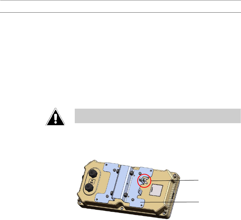
This architecture is used for setups with minimum of auxiliary equipment
needed on the roadside. The transceiver includes all functionality to run the
complete application.
The system is scalable up to 2 lanes and is based on a master slave
principle, where the MTX acts as a master.
• The transceivers have to be supplied with an external 24-48V DC power
supply unit.
• Each Transceiver is internally protected against reverse polarity and
surges.
Caution: An over-voltage protection unit has to be used to protect the
auxiliary equipment against
The following types of Localization Transceivers are available for the
“compact architecture”.
System Type Part No. Description
Compact MTX-9450 34026470100 Master Transceiver
TRX-9450 34026470000 Slave Transceiver
See application notes
Length: from, 33feet (10m) up to 260feet (80m).
See chapter “Connection Cable (Ethernet + Power Supply)” on page 19.
The maximum length is limited to 80m.
For standard cables please refer to chapter Line Connection Cable (Ethernet
+ Power Supply) on page 21
A transient protection unit which consists of the two modules TCM and TIM
must be used at the roadside.
Scope
System structure
Figure 3
System variant “Line application
with Master-Transceiver“
Transceivers
Table 7
Localization Transceivers for the
system variant “Line application
with Master-Transceiver”
Installation
Connection Cable
Line Cable
Transient Protection Unit

Page 16 of 26 Technical Manual | WAVE Transceiver with precise localization capability MTX-9450 and TRX-9450
1000005502-THb-02
Module
Description
Kapsch
Part No.
TCM-0902 Module for up to two TIM modules 34019410000
TIM-5310* Module for Line application
(48V / 2.5A fuse, type slow blowing)
34026560000
* Quantity: One (1) TIM module per TRX
For more detailed information see the technical manual of the transient
protection unit (Doc. No. 1000002917 or 1000003873).
The power supply must be mounted in the roadside cabinet. The power
supply for the transceiver has to fulfill the requirements for a SELV-circuit
(Safety Extra Low Voltage). The recommended supply voltage is 48V DC. A
UL compliant industrial power supply must be used.
Recommended power supplies see Table 5 on page 14.
Table 8
Available TCM and TIM modules
Power supply
Technical Manual | WAVE Transceiver with precise localization capability MTX-9450 and TRX-9450 Page 17 of 26
1000005502-THb-02
Installation
The described mounting applies to all transceivers specified in this
documentation.
Mounting position and height
• The antenna should point towards the direction of traffic flow.
• The mounting device offers the possibility to adapt to different
environments, for example mounting under a ceiling is possible.
Warning: When mounting the bracket to a bridge, a gantry or a wall the
appropriate safety regulations must be followed.
Mounting plate for MTX-9450 and TRX-9450
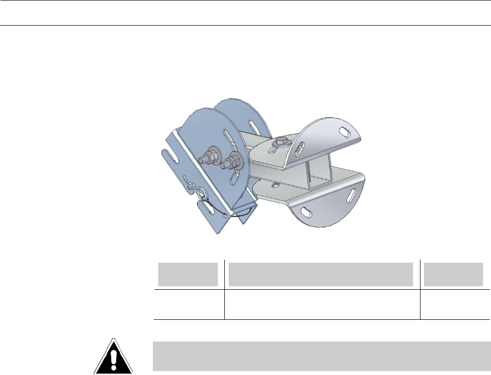
The mounting plate is part of the transceiver and must not be removed.
Figure 4
Mounting plate for MTX-9450 and
TRX-9450
Ground
point
Mounting
Plate
Page 18 of 26 Technical Manual | WAVE Transceiver with precise localization capability MTX-9450 and TRX-9450
1000005502-THb-02
Bracket for MTX-9450 and TRX-9450
Module
Description
Kapsch
Part No.
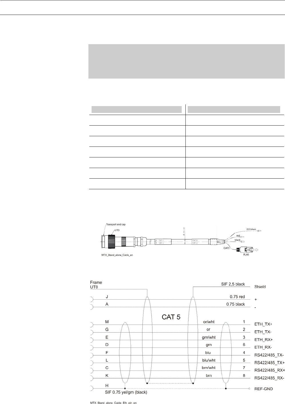
Bracket for
MTX/TRX
Bracket for installation of MTX/TR 34017690000
Warning: Installation of the MTX-9450/TRX-9450 product must be
performed by trained Kapsch approved staff.
Figure 5
Bracket for MTX-9450 and
TRX-9450
Technical Manual | WAVE Transceiver with precise localization capability MTX-9450 and TRX-9450 Page 19 of 26
1000005502-THb-02
Electrical Installation
Remark: The cables must be protected against mechanical damage.
Optimal protection offers a protective cable guard. Cables must be fixed
with cable strap in such a way that the maximum protection against
mechanical damage is provided.
Connection Cable (Ethernet + Power Supply)
Part number Cable length
34015780100 33 feet (10m)
34015780140 46 feet (14m)
34015780180 59 feet (18m)
34015780220 72 feet (22m)
34015780260 85 feet (26m)
34015780300 98 feet (30m)
34015780500 164 feet (50m)
Other lengths are available on request.
Recommendation for
cabling
Table 9
Available lengths of
Connection Cable
Figure 6
Connection Cable
(Ethernet + Power Supply)
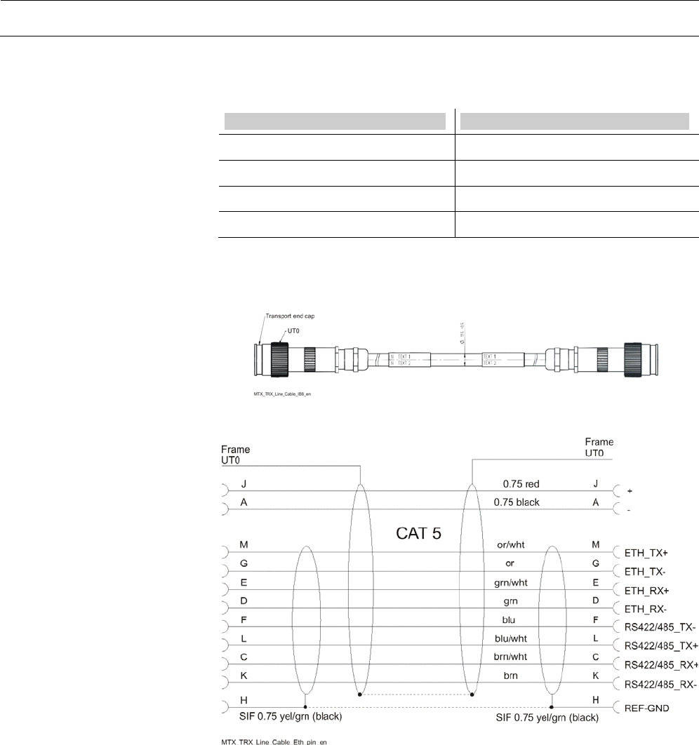
Figure 7
Connector pin assignment
Connection Cable
(Ethernet + Power Supply)
to protection unit TCM/TIM
IPC
Shield
24 or 48V DC
MTX
IN
Page 20 of 26 Technical Manual | WAVE Transceiver with precise localization capability MTX-9450 and TRX-9450
1000005502-THb-02
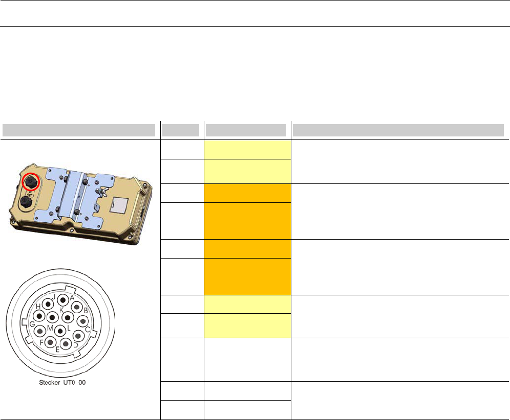
Signals at connector “IN” of MTX-9450/TRX-9450
Connector Pin Signal Description
MTX-9450/TRX-9450 “IN”
UT0 Connector male
M ETH_TX+ Ethernet:
Positive / negative line, isolated, Transmit-line
from transceiver to TRC-1040-E.
G ETH_TX-
C RS422/485_RX+ Service:
Receive-line to transceiver.
RS422/485:
Positive / negative line, 5Vp-p,
K RS422/485_RX-
L RS422/485_TX+ Service:
Transmit-line from transceiver, isolated.
RS422/485:
Positive / negative line, 5Vp-p.
F RS422/485_TX-
E ETH_RX+ Ethernet:
Positive / negative line, isolated, Receive-line
from TRC-1040-E to transceiver.
D ETH_RX-
H REF-GND REF-GND, reference ground for RS485:
Connected with internal galvanic isolated GND
via choke.
J + Power line:
24V-48V DC, input
A -
Table 10
Signals at connector “IN” of
MTX-9450/TRX-9450
Technical Manual | WAVE Transceiver with precise localization capability MTX-9450 and TRX-9450 Page 21 of 26
1000005502-THb-02
Line Connection Cable (Ethernet + Power Supply)
Part number Cable length [m]
34017450050 16 feet (5m)
34017450070 23 feet (7m)
34017450100 33 feet (10m)
34017450150 49 feet (15m)
Other lengths are available on request.
Table 11
Available cable lengths
Line Connection Cable
Figure 8
Line Connection Cable
(Ethernet + Power Supply)
Figure 9
Connector pin assignment
Line Connection Cable
(Ethernet + Power Supply)
TRX
IN
MTX
OUT
Page 22 of 26 Technical Manual | WAVE Transceiver with precise localization capability MTX-9450 and TRX-9450
1000005502-THb-02
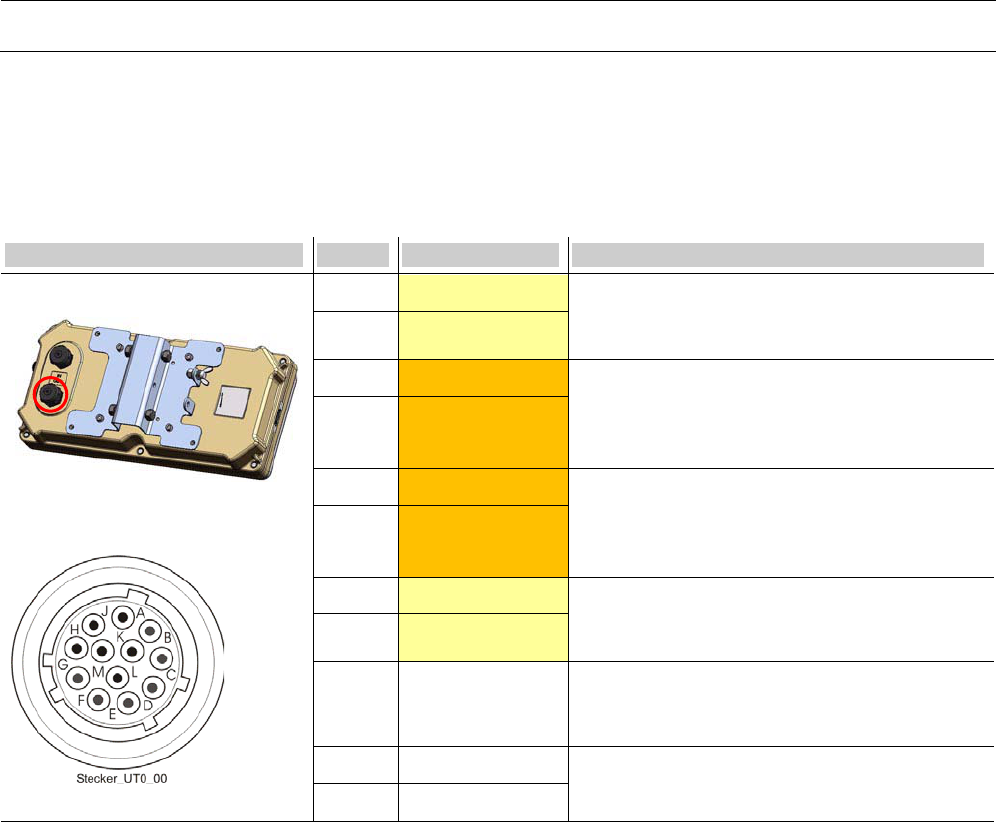
Signals at connector “OUT” of MTX-9450
Connector Pin Signal Description
MTX-9450 “OUT”
UT0 Connector male
M ETH_TX+ Ethernet:
Positive / negative line, isolated, Transmit-line
from transceiver to TRC-1040-E.
G ETH_TX-
C RS422/485_RX+ Service:
Receive-line to transceiver.
RS422/485:
Positive / negative line, 5Vp-p,
K RS422/485_RX-
L RS422/485_TX+ Service:
Transmit-line from transceiver, isolated.
RS422/485:
Positive / negative line, 5Vp-p.
F RS422/485_TX-
E ETH_RX+ Ethernet:
Positive / negative line, isolated, Receive-line
from TRC-1040-E to transceiver.
D ETH_RX-
H REF-GND REF-GND, reference ground for RS485:
Connected with internal galvanic isolated GND
via choke.
J + Power line:
24V-48V DC, output
A -
Table 12
Signals at connector “OUT” of
MTX-9450

Technical Manual | WAVE Transceiver with precise localization capability MTX-9450 and TRX-9450 Page 23 of 26
1000005502-THb-02
Product Specifications
Transceivers MTX-9450 and TRX-9450
Dimensions [LxWxH] 16.5 in x 7.9 in x 3.4 in
(420mm x 200mm x 86mm)
Weight without bracket <16 pounds (<7 kg)
Material of housing Alloy die casting, Radom: Polycarbonate
Wind load 70 km/h (43.5 mph) – 34.5 N
120 km/h (74,6 mph) – 100 N
140 km/h (87.0 mph) – 137.5 N
160 km/h (99.4 mph) – 180 N
Interface Specification
Rated Input Voltage Nom. 24V DC up to 48V DC
Input Voltage Range Min: 21.6V DC (=24V – 10%) permanent
Max: 52.8V DC (=48V + 10%) permanent
Protection The Transceiver is internally protected against
reverse polarity of the input voltage and internally
fused with 3A (type slow blowing). The fuse cannot
be changed by the user.
Power consumption
at maximum transmit
power
MTX 24W typical
TRX 24W typical
Radio 1
Frequency range 5.850GHz - 5.920GHz
Channels Channels: 172,174,176,178,180,182,184
Data Rates 3MBit/s – 27MBit/s
Antenna Polarization Right hand circular
Radiated power
External Antenna N-
Connector (MTX only)
≤ 33dBm EIRP
≤20dBm conducted
Radio 2
Frequency range 5.850GHz - 5.920GHz
Channels Channels: 172,174,176,178,180,182,184
Data Rates 3MBit/s – 27MBit/s
Antenna Polarization
Radiated power
External Antenna N-
Connector (MTX only)
Right hand circular
≤ 20dBm EIRP
≤ 10dBm conducted
Mechanical characteristics
Electrical characteristics
and conditions
RF Interfaces

Page 24 of 26 Technical Manual | WAVE Transceiver with precise localization capability MTX-9450 and TRX-9450
1000005502-THb-02
GPS Interface
Connector Type
Antenna Type
N-Connector female
Active GPS Antenna
Temperature (operation) -30°C ...+55°C (ASTM Type 2)
-22F … 131F
Temperature (storage) -40°C ...+70°C
-40F … 158F
IEC protection rating NEMA 4X
Oscillation 3.5mm / (1...9)Hz
10m/s² / (9...150)Hz
Shock 150m/s² / 11ms
47 CFR Part 90 M
47 CFR Part 15 B
UL-60950-1, 2nd edition
UL-60950-22, 2nd edition
CSA C22.2 No. 60950-1-07, 2nd edition
UL: E323290
Environmental conditions
Compliance

Technical Manual | WAVE Transceiver with precise localization capability MTX-9450 and TRX-9450 Page 25 of 26
1000005502-THb-02
Conformity
Standards
Ref. Standard Description
[1] ASTM E2213 - 03 Standard Specification for
Telecommunications and Information
Exchange Between Roadside and Vehicle
Systems — 5 GHz Band Dedicated Short
Range Communications (DSRC) Medium
Access Control (MAC) and Physical Layer
(PHY) Specifications
[2] IEEE 802.11™a-2007 IEEE Standard for Information technology—
Telecommunications and information
exchange between systems—
Local and metropolitan area networks—
Specific requirements
Part 11: Wireless LAN Medium Access Control
(MAC) and Physical Layer (PHY)
Specifications
[3] IEEE 802.11™p IEEE Standard for
Information technology—
Telecommunications and information
exchange between systems—
Local and metropolitan area networks—
Specific requirements Part 11: Wireless LAN
Medium Access Control (MAC) and Physical
Layer (PHY) Specifications
Amendment 7: Wireless Access in Vehicular
Environments
[4] IEEE 1609.4™ Draft Standard for Wireless Access in
Vehicular Environments (WAVE) - Multi-
channel Operation
[5] IEEE 1609.3™ Draft Standard for Wireless Access in
Vehicular Environments (WAVE) – Networking
Services
Table 13
Standards

Page 26 of 26 Technical Manual | WAVE Transceiver with precise localization capability MTX-9450 and TRX-9450
1000005502-THb-02
For further information please contact:
Kapsch TrafficCom U.S. Corp.
21515 Ridgetop Circle, Suite 290
Sterling, VA 20166
Phone: +1 (703) 885 1976
Kapsch TrafficCom AG
Am Europlatz 2
A-1120 Vienna
Phone: +43 (0)50 811 0
Fax: +43 (0)50 811 2589
E-mail: kapsch.at@kapsch.net
Address