Kapsch Trafficcom 9955 Onboard Unit Programming Station User Manual
Kapsch Trafficcom AG Onboard Unit Programming Station
User Manual

Kapsch TrafficCom AG
User Manual
Onboard Unit Programming
Station OPS-9955
This device is based on the IEEE WAVE Standards
1000005508-Bed-02

1000005508-Bed-02
Document number 1000005508
Document type Bed
Document version 02
Document status released
Date of release 2010-04-21
Valid from
Software version -
Created by: Batko Manfred
Checked by: Povolny Robert
Approved by: Dreschl Werner
Disclaimer and Limitation of Liability
The products described in this manual are provided “as is” and without any warranties of any
kind, either express or implied. Kapsch TrafficCom disclaims all warranties, express or implied,
including, but not limited to, warranties of title, legality or non-infringement or misappropriation
of any intellectual property rights of third parties or implied warranties of merchantability or
fitness for a particular purpose. Under no circumstances will Kapsch TrafficCom (including its
affiliates, licensors, contractors, suppliers, assignees, subsidiaries, and the respective officers,
directors, employees, shareholders, agents and representatives of each of them) be liable for any
expenses, fees, claims, damages or losses in any way relating to or arising out of the products
described in this manual. Applicable law may not allow certain warranty exclusions, so one or
more of the above disclaimers may not apply to you.
Copyright Kapsch TrafficCom AG 2010
Duplication as well as utilization of contents of this documentation are illegal without our explicit consent.

User Manual | Onboard Unit Programming Station OPS-9955 Page 3 of 19
1000005508-Bed-02
Table of Contents
Page
Information about this document 5
Text conventions ............................................................................................. 5
Important text elements ................................................................................... 5
Abbreviations ................................................................................................... 6
Regulatory Information 7
Software Licenses 8
Safety Instructions 8
Environmental Information 8
Visual Inspection 8
Maintenance Instructions 8
General Information 9
Definitions ........................................................................................................ 9
Cleaning the OPS 9
System Overview 10
Functional details .......................................................................................... 11
Modes of Operation ....................................................................................... 11
Installation and Operation 12
Fault Diagnosis 16
Product Specifications 17
Conformity 18
Standards ...................................................................................................... 18

Page 4 of 19 User Manual | Onboard Unit Programming Station OPS-9955
1000005508-Bed-02
List of figures
Figure 1 System overview ............................................................................ 10
Figure 2 Onboard Unit Programming Station OPS ...................................... 12
Figure 3 Connectors on the OPS ................................................................. 12
Figure 4 HMI Interface on the OPS .............................................................. 13
Figure 5 OPS connecting scheme ............................................................... 13
Figure 6 Correct positions of packed OBUs ................................................ 14
Figure 7 Incorrect positions of packed OBUs .............................................. 14
Figure 8 Correct positions of unpacked OBUs ............................................. 14
Figure 9 Incorrect positions of unpacked OBUs .......................................... 15
List of tables
Table 1 Abbreviations and definitions ............................................................. 6
Table 2 Connectors on the OPS ................................................................... 12
Table 3 HMI Interface .................................................................................... 13
Table 4 Standards ......................................................................................... 18
User Manual | Onboard Unit Programming Station OPS-9955 Page 5 of 19
1000005508-Bed-02
Information about this document
This document is for professionals setting up and maintaining the
equipment.
Professionals are persons, who have basic knowledge on software
installation and computer networks.
This User Manual shall be carefully read before installation.
Text conventions
Visual aids and standard text formats in this manual help the reader to locate
and identify information easily.
Typographical formats:
Style
Used for
bold
Accentuations
italics
Labelling and cross-references
CAPITAL LETTERS
Acronyms
Note: Contains additional information on the topic.
Important text elements
This manual contains specific Caution and Warning statements. These shall
be interpreted as follows:
Attention: This warning indicates that the device may be affected by
Electrostatic Discharge. Appropriate precautions must be made to avoid
damage to the device.
Caution: Indicates a hazardous situation which, if not avoided, could
result in minor or moderate injury.
Warning: Indicates a hazardous situation which, if not avoided, could
result in death or serious injury.
Audience
Preparations
Table 1
Text formats and their meaning
Attention
Caution
Warning

Page 6 of 19 User Manual | Onboard Unit Programming Station OPS-9955
1000005508-Bed-02
Abbreviations
DSRC
Dedicated Short Range Communication
GUI
Graphical User Interface
OBU
Onboard Unit (adjustable by user)
OPS
Onboard Unit Programming Station
RF
Radio frequency
WAVE
Wireless Access in Vehicular Environments
Table 1
Abbreviations and definitions

Regulatory Information Page 7 of 19
1000005508-Bed-02
Regulatory Information
This device complies with Part 15 of the FCC Rules. Operation is subject to
the following two conditions:
1. This device may not cause harmful interference, and
2. this device must accept any interference received, including
interference that may cause undesired operation.
Changes or modifications made to this equipment not expressly approved by
Kapsch may void the FCC authorization to operate this equipment.
Note: This equipment has been tested and found to comply with the
limits for a Class B digital device, pursuant to Part 15 of the FCC Rules.
These limits are designed to provide reasonable protection against
harmful interference in a residential installation. This equipment
generates uses and can radiate radio frequency energy and, if not
installed and used in accordance with the instructions, may cause
harmful interference to radio communications. However, there is no
guarantee that interference will not occur in a particular installation. If
this equipment does cause harmful interference to radio or television
reception, which can be determined by turning the equipment off and
on, the user is encouraged to try to correct the interference by one or
more of the following measures:
• Reorient or relocate the receiving antenna.
• Increase the separation between the equipment and receiver.
• Connect the equipment into an outlet on a circuit different from
that to which the receiver is connected.
• Consult the dealer or an experienced radio/TV technician for help.
This equipment complies with FCC radiation exposure limits set forth for an
uncontrolled environment. This equipment should be installed and operated
with minimum distance of 20 cm (8 inches) between the radiator and a
human body. Failure to do so could result in bodily injury or death.
This transmitter must not be co-located or operating in conjunction with any
other antenna or transmitter.
Notice
Notice
Class B digital device
Radio frequency radiation
exposure Information
Page 8 of 19 User Manual | Onboard Unit Programming Station OPS-9955
1000005508-Bed-02
Software Licenses
This product may contain software portions including technologies used
under third party license, and are copyrighted. Notices, Terms and
Conditions pertaining to third party software are located at
http://www.kapsch.net/us/en/ktc/portfolio/products_and_components/Pa
ges/default.aspx
Safety Instructions
Warning: This device is used with an external power supply, which is
connected to 110-230V AC power. Always check the cables for damage
before connecting the power supply to AC.
Environmental Information
Your equipment set consists of material that can be recycled. Please follow
the local regulations regarding the disposal of packaging material and waste
electronics equipment.
This device is designed for office use only and must not be used outdoors.
Visual Inspection
After unpacking please check the equipment for possible damage. If the
content is incomplete or damaged please contact your local Kapsch office.
Maintenance Instructions
Warning: Regular inspection of installed equipment is mandatory and
shall be in accordance with local safety regulations. Cables shall be
checked for damage and plugs for correct fit in the outlet to prevent
electrical shock to humans or damage to the device.
Recycling
Environmental
requirements
General Information Page 9 of 19
1000005508-Bed-02
General Information
Definitions
The integrator is responsible for technical integration of the OPS-9955 into a
point-of-sale infrastructure defined by the operator.
The operator defines the process of handling OBUs in the point-of-sale
infrastructure and the use in the particular system configuration.
The customer has a commercial contract for the offered services.
The Point-of-Sale Terminal runs application and driver software to control
the OPS-9955.
During personalization process customer specific data may be stored on the
OBU and/or the OBU is enabled in the system. The data stored on the OBU,
may depend on the particular system, operator and/or application.
Cleaning the OPS
Note: The housing of the OPS may be cleaned only with a clean, damp,
lint free cloth. Do not use liquids to clean the OPS. This may damage
the product and can result in injury.
Integrator
Operator
Customer
Point-of-Sale Terminal
Personalization Process
Page 10 of 19 User Manual | Onboard Unit Programming Station OPS-9955
1000005508-Bed-02
System Overview
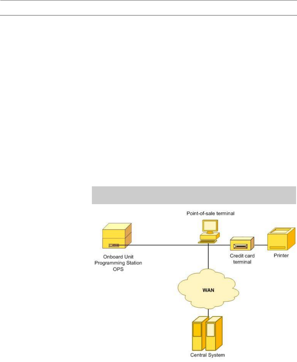
A typical point-of-sale installation consists of the OPS-9955, a Point-of-Sale
Terminal and auxiliary equipment which depends on the needs of the
operator. The Point-of-Sale Terminal is a PC which is connected to a
network infrastructure in most system configurations.
The OPS-9955 is a communications device for data exchange between the
Point-of-Sale Terminal and the OBU according to the WAVE standards.
The OPS is designed for office use. It will be powered by an external power
supply, which is connected to AC power. Ethernet is used for data exchange
between OPS-9955 and the Point-of-Sale Terminal.
The software package delivered by KAPSCH includes driver software for the
OPS-9955 to integrate the device with a Point-of-Sale Terminal. See
Programmer’s Manual for details.
Note: The OPS-9955 cannot be used without installing the KAPSCH
software package on the user terminal.
Generic Programming Interface for Integrators
Intuitive Operation
Personalization of Packed and Unpacked OBUs without the need of
exact positioning
Maximum size of programmable OBUs up to 40x155x110mm
(1.5in x 6.1in x 4.3in) (HxLxW)
Hardware
Software
Figure 1
System overview
OPS features

System Overview Page 11 of 19
1000005508-Bed-02
Anti-slip protection
Easy to clean
Functional details
The generic programming capability gives the integrator the flexibility to have
nearly full access to all information stored on the OBU.
Key features:
Personalize OBUs with customer data
Modify customer data on the OBU
Read out customer data stored on the OBU
Set the operating state of the OBU
Test the OBU for basic operation
Modes of Operation
Passive Mode:
In this mode the radio of the OPS-9955 is not transmitting and it is
waiting for a personalization request. The Ethernet interface is enabled
and the current state of the device is signaled via the HMI interface.
Active Mode:
The radio of the OPS-9955 will transmit during the communication
process with the OBU and will automatically enter Passive Mode after
completing the steps needed for personalization. If the lid of the OPS-
9955 is opened during transmission, the transmission of the OPS-9955
radio will be stopped immediately.
Page 12 of 19 User Manual | Onboard Unit Programming Station OPS-9955
1000005508-Bed-02
Installation and Operation
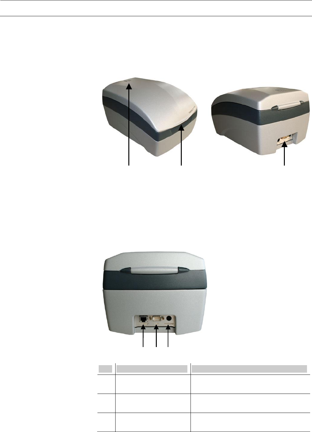
Connectors
Status LEDs
Recessed grip
Place the OPS on a desk or other flat surface in a horizontal position.
Connect the OPS to the Point-of-Sale by using a RJ45 cable.
Connect the external power supply to the OPS.
Connect the external power supply to the 110VAC - 230VAC outlet.
The green Power LED is illuminated continuously.
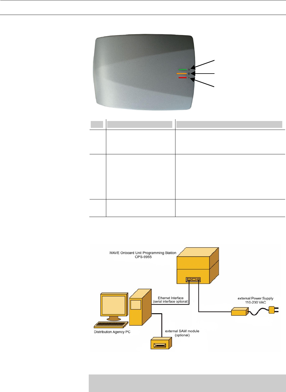
1
3
2
No.
Name
Description
1
RJ45 Ethernet Connector
(female)
RJ45 connector to connect the Ethernet
cable to the Point-of-Sale Terminal
2
RS232 Connector (male)
D-Sub 9-pin RS232 connector for service
purposes only.
3
Power Supply Connector
(male)
Power Supply connector 12 – 24VDC for
connecting the external Power supply.
Figure 2
Onboard Unit Programming
Station OPS
1. Mounting
2. Connecting
Figure 3
Connectors on the OPS
Table 2
Connectors on the OPS
Installation and Operation Page 13 of 19
1000005508-Bed-02
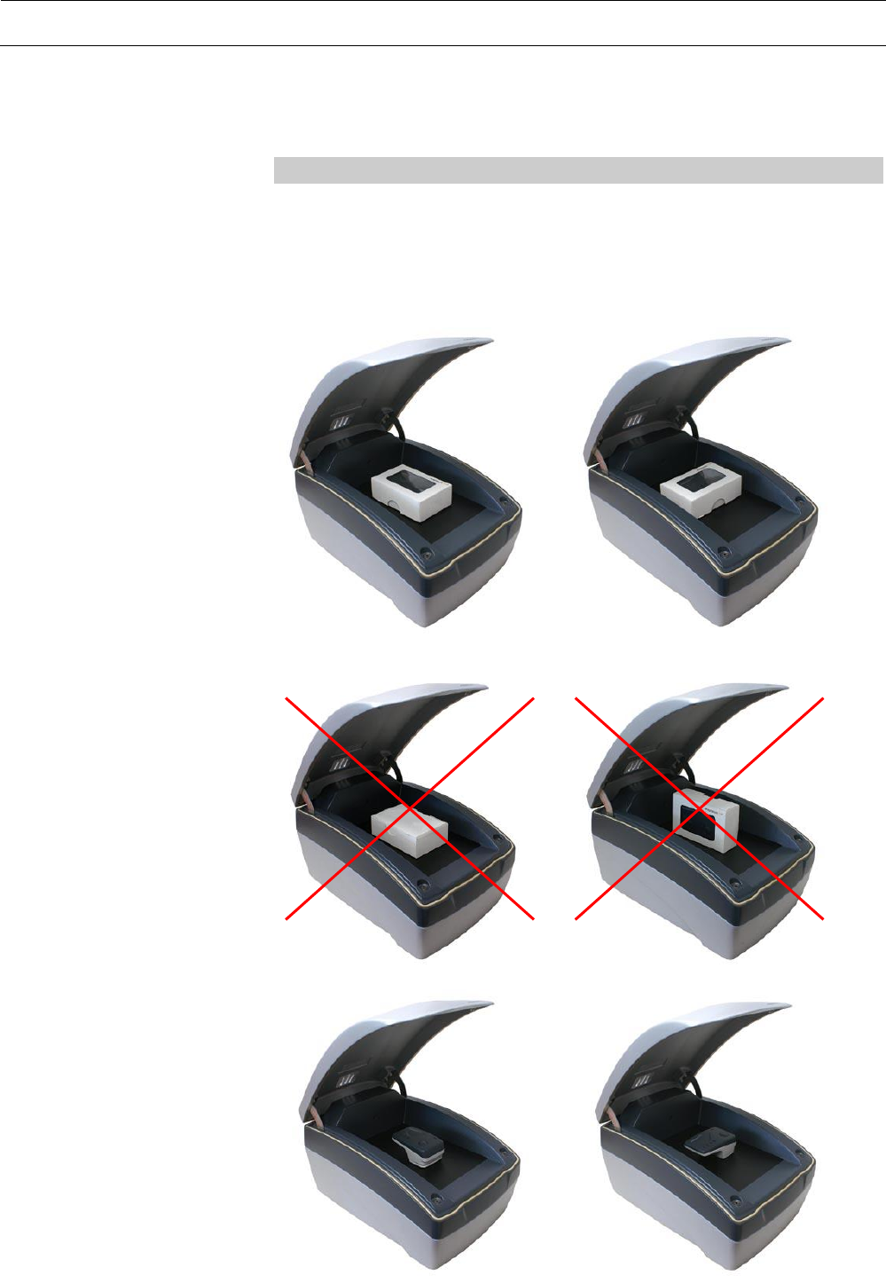
1
2
3
No.
Name
Description
1
Power LED (green)
After connecting the power supply of the
OPS to AC power, the Power LED is
illuminated GREEN continuously.
2
Programming LED
(orange)
After the OPS is initialized and the lid is
closed the Programming LED is
illuminated continuously ORANGE. After
successful personalization of the OBU the
Programming LED flashes until the lid is
opened.
3
Error LED (red)
In case of an error the Error LED flashes
RED.
By default the OPS gets its network configuration via DHCP.
Note: A DHCP Server must be installed on the Point-of-Sale Terminal
before connecting the OPS.
Figure 4
HMI Interface on the OPS
Table 3
HMI Interface
Figure 5
OPS connecting scheme
3. Network configuration
Page 14 of 19 User Manual | Onboard Unit Programming Station OPS-9955
1000005508-Bed-02
The OPS is ready for personalization, if the orange LED lights
continuously. (If not see section Fault Diagnosis, page 16).
Note: The lid of the OPS must be closed.
Open the lid by pushing the lid slightly at the grip in front of the OPS.
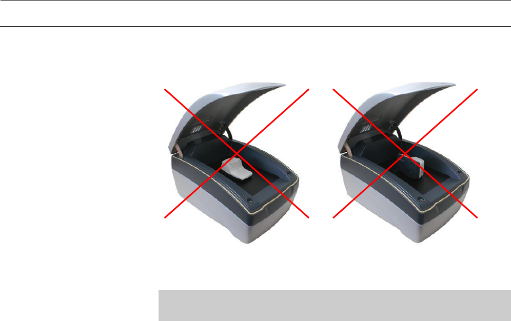
Place a packed or unpacked OBU as shown in Figures 7 – 10 in the
OPS.
4. Start-up
5. OBU Positioning
Figure 6
Correct positions of packed OBUs
Figure 7
Incorrect positions of packed
OBUs
Figure 8
Correct positions of unpacked
OBUs
Installation and Operation Page 15 of 19
1000005508-Bed-02
Close the lid of the OPS and start the personalization procedure.
Note: Do not open the lid during personalization procedure or the
personalization will be canceled.
After a successful personalization the orange LED starts flashing.
Open the lid of the OPS and remove the OBU
Close the lid of the OPS. The orange LED stops flashing and is
illuminated continuously again.
Figure 9
Incorrect positions of unpacked
OBUs
6. End of personalization

Page 16 of 19 User Manual | Onboard Unit Programming Station OPS-9955
1000005508-Bed-02
Fault Diagnosis
Problem
Cause
Repair
Power LED (green)
isn´t illuminated
Power supply plug from
the external power
supply is not connected
to a live AC outlet
Connect the power supply
plug from the external power
supply to a live AC outlet.
Power supply cable from
the external power
supply is not connected
to the OPS
Connect the power supply
cable from the external power
supply to the power connector
on the OPS
Fuse is blown
Contact the Sales or Service
Organization of
Kapsch TrafficCom
Programming LED
(orange) isn´t
illuminated
Lid of the OPS is open
Close the lid of the OPS
Programming LED
(orange) isn´t
illuminated
OPS software driver is
not installed correctly
Install or reinstall the
KAPSCH software package
OPS doesn´t
communicate with
the Point-of-Sale
Terminal
Ethernet cable is not
connected properly or
Ethernet cable is defect
Connect the Ethernet cable
correctly
OPS doesn´t
communicate with
the Point-of-Sale
Terminal
OPS software driver is
not installed correctly
Install or reinstall the
KAPSCH software package
Error LED (red)
flashes
General error
Contact the Sales or Service
Organization of
Kapsch TrafficCom

Product Specifications Page 17 of 19
1000005508-Bed-02
Product Specifications
Dimensions [LxWxH]
11.8 in x 7.8 in x 6.3 in
(300 mm x 200 mm x 160 mm)
Weight
10.4 pounds (4.7 kg)
Power supply
External power supply 12VDC / 2A
Power consumption
(operating mode)
max. 24W
typ. 2.7W
Temperature (operation)
-5°C … +50°C
23°F … +122°F
Storage temperature
-20°C … +70°C
-4°F … +158°F
Ambient humidity
5 to 95% non condensing
100Base-TX
RJ45 connector
Connector for a Ethernet connection to Point-of-Sale
Terminal
Network configuration
DHCP
D-Sub 9-pin male
RS232 connector for service issues
Frequency range
5.850GHz - 5.925GHz
Channels
172,174,176,178,180,182,184
Data Rates
3MBit/s – 27MBit/s
47 CFR Part 95 L
47 CFR Part 15 B
UL-60950-1, 2nd edition
UL-60950-22, 2nd edition
CSA C22.2 No. 60950-1-07, 2nd edition
UL: E323290
Mechanical data
Electrical data
Environmental conditions
Ethernet Interface
RS232 Interface
RF Interfaces
Compliance

Page 18 of 19 User Manual | Onboard Unit Programming Station OPS-9955
1000005508-Bed-02
Conformity
Standards
Ref.
Standard
Description
[1]
ASTM E2213 – 03
Standard Specification for
Telecommunications and Information
Exchange Between Roadside and Vehicle
Systems — 5 GHz Band Dedicated Short
Range Communications (DSRC) Medium
Access Control (MAC) and Physical Layer
(PHY) Specifications
[2]
IEEE 802.11™a-2007
IEEE Standard for Information technology—
Telecommunications and information
exchange between systems—
Local and metropolitan area networks—
Specific requirements
Part 11: Wireless LAN Medium Access Control
(MAC) and Physical Layer (PHY)
Specifications
[3]
IEEE 802.11™p
IEEE Standard for
Information technology—
Telecommunications and information
exchange between systems—
Local and metropolitan area networks—
Specific requirements Part 11: Wireless LAN
Medium Access Control (MAC) and Physical
Layer (PHY) Specifications
Amendment 7: Wireless Access in Vehicular
Environments
[4]
IEEE 1609.4™
Draft Standard for Wireless Access in
Vehicular Environments (WAVE) - Multi-channel
Operation
[5]
IEEE 1609.3™
Draft Standard for Wireless Access in
Vehicular Environments (WAVE) – Networking
Services
Table 4
Standards

Conformity Page 19 of 19
1000005508-Bed-02
For further information please contact Kapsch TrafficCom.
Kapsch TrafficCom U.S. Corp.
21515 Ridgetop Circle, Suite 290
Sterling, VA 20166
Phone: +1 (703) 885 1976
Kapsch TrafficCom AG
Am Europlatz 2
A-1120 Vienna
Phone: +43 (0)50 811 0
Fax: +43 (0)50 811 2589
E-mail: kapsch.at@kapsch.net
Address