Karlnet 0003 802.11 Wireless Bridge User Manual 403286
Karlnet Inc. 802.11 Wireless Bridge 403286
Karlnet >
Contents
- 1. CSU Manual Revised
- 2. RSU Manual Revised
CSU Manual Revised
525 Metro Place North, Suite 100
Dublin, OH 43017
Office: 614-822-5275
Fax: 614-822-0024
www.KarlNet.com
1
KarlNet
KarlNet Inc.
Networkin
g
you
r
Wireless Worl
d
KarlNet Customer Premise Equipment
(CPE) Outdoor Family of Products
Setup and Installation Manual (Rev. B)
Small-Office Subscriber Units
(Model Number SSU-0124BR-SGxxxx)
Corporate Subscriber Units
(Model Numbers CSU-0124BR-SGxxxx)
© 2003 KarlNet, Inc. All rights reserved. Printed in the U.S.A

525 Metro Place North, Suite 100
Dublin, OH 43017
Office: 614-822-5275
Fax: 614-822-0024
www.KarlNet.com
2
KarlNet
TABLE OF CONTENTS
TABLE OF CONTENTS.................................................................................................... 2
FCC NOTICE ..................................................................................................................... 3
WARRANTY ..................................................................................................................... 4
PRODUCT DESCRIPTION............................................................................................... 5
PACKING LIST ................................................................................................................. 6
THEORY OF OPERATIONS ............................................................................................ 7
FEATURES ........................................................................................................................8
INSTALLATION ............................................................................................................... 9
Mount the Unit................................................................................................................ 9
General Mounting Considerations .............................................................................. 9
Power up the Unit ........................................................................................................... 9
Configure the Unit ........................................................................................................ 11
Align and Test the Unit................................................................................................. 11
Before Running the Link Test................................................................................... 11
Running the Link Test .............................................................................................. 16
CONTACT........................................................................................................................ 21

525 Metro Place North, Suite 100
Dublin, OH 43017
Office: 614-822-5275
Fax: 614-822-0024
www.KarlNet.com
3
KarlNet
FCC Declaration of Conformity
Responsible party:
KarlNet, Inc.
525 Metro Place N., Suite 100
Dublin, OH 43017
(614) 822 – 5275 Fax: (614) 822 - 2400
We, KarlNet, Inc. declare that the wireless networking equipment described herein :
(1) Compleis with FCC radiation exposure limits set forth for an uncontrolled
environment when installed as directed.
(2) Meets Class B emission requirements and complies with Part 15 of the FCC rules.
Operation is subject to the following two conditions:
• This device may not cause harmful interference.
• This device must accept any interference received, including interference
that may cause undesired operation.
FCC Notice
This equipment should be professionally installed, and the installer is responsible for
ensuring that the system is used exclusively for fixed, point-to-point or fixed point-to-
multipoint operations. The equipment should be installed and operated as fix-mounted
antennas such that the main lobe(s) of these antennas are located a minimum of 2 meters
between the antenna and all persons during normal operation. Users and installers must
adhere to the antenna installation instructions and transmitter operating conditions for
satisfying RF exposure compliance set forth under Part 15 of the FCC regulations. Failure
to do so, or changing/modifying the unit may void the user’s authority to operate the
equipment.
2004 KarlNet, Inc. All Rights Reserved. No part of parts of this document may be
reproduced, translated, stored in any electronic retrieval system or transmitted, in any
form or by any means, electronic, mechanical, photocopied, recorded or otherwise,
without the prior written permission of KarlNet, Inc.

525 Metro Place North, Suite 100
Dublin, OH 43017
Office: 614-822-5275
Fax: 614-822-0024
www.KarlNet.com
4
KarlNet
WARRANTY
KarlNet, Inc. warrants that your device is free of defects in material and
workmanship for a period of one year after initial purchase. KarlNet will, in this
period of time, repair or replace, any KarlNet product returned to the factory,
freight prepaid.
The KarlNet warranty covers repairs or replacement (at KarlNet’s option) of the
product only. KarlNet is not responsible for the cost of removal, reinstallation, or
shipping to the place of repair. KarlNet does not extend or modify its warranty
period as a result of repair or replacement.
KarlNet reserves the right to void a warranty and/or make reasonable charges for
repair of a unit if the warranty seal is broken or the unit displays evidence of
misuse, abuse, or tampering.
KarlNet is not responsible for damage to any other equipment or property, or any
other consequential or incidental damages of any kind, whether based on
contract, negligence, or strict liability. Maximum liability shall not in any case
exceed the purchase price of the unit.
Warranties give you (the buyer) specific legal rights. You may also have other
rights that vary from state to state. This warranty is only extended to purchases
made in the United States of America or its possessions.
SPECIAL WARRANTY NOTICE
The system warranty is null and void if any of the following occurs:
1. The product enclosure is opened.
2. The system connections are not properly waterproofed.
3. The device is installed improperly or with incorrect connectors.
4. The antenna or DC Power Injector are physically damaged.
5. The device is operated outside the recommended DC power specifications.
6. The device is damaged by extreme forces of nature, lightning, or ‘Acts of God.’

525 Metro Place North, Suite 100
Dublin, OH 43017
Office: 614-822-5275
Fax: 614-822-0024
www.KarlNet.com
5
KarlNet
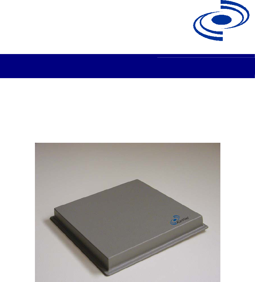
PRODUCT DESCRIPTION
Thank you for purchasing KarlNet’s Customer Premise Equipment (CPE) Outdoor
wireless networking devices. This guide explains how to install the hardware devices,
and provides power and cabling guidelines.
KarlNet offers two high-speed outdoor CPE networking systems that provide point-to-
multipoint and point-to-point connectivity to enterprise and service providers.
The TurboCell Small Office Subscriber Unit (SSU) is designed specifically for
medium-to-large fixed wireless networks that demand higher performance
because of high traffic. The SSU is used as a remote station that connects to a
KarlNet WISP base station (WBS), and can be used in either a point-to-point or
point-to-multipoint network. The SSU supports limited users, providing a low
cost, easy to install solution that is ideal for residential or small office locations.
This cost effective, FCC approved unit provides higher gain and better
performance.
The TurboCell Corporate Subscriber Unit (CSU) is designed specifically for large
fixed wireless networks that demand higher performance and security. The CSU
comes complete with KarlNet’s firewall software, and supports an unlimited
number of users. The CSU is used as a remote station that connects to a KarlNet
WISP base station (WBS), and can be used in either a point-to-point or point-to-
multipoint network. The CSU supports an unlimited number of users and provides
a low cost, easy to install unit designed for businesses or other large networks.
Featuring KarlNet’s powerful circuit boards, radios, and systems, and KarlNet’s award-
winning industry standard TurboCell™ software, the SSU and CSU offer the best value
in the outdoor wireless industry.

525 Metro Place North, Suite 100
Dublin, OH 43017
Office: 614-822-5275
Fax: 614-822-0024
www.KarlNet.com
6
KarlNet
PACKING LIST
Your package contains the following items:
A KarlNet Customer Premise Equipment (CPE) Outdoor wireless hardware unit
(either SSU or CSU) and associated mounting bracket
A Power over Ethernet (PoE) Injector
A DC power supply
An Ethernet coupler
A “Getting Started” CD that contains the KarlNet Configurator, online help for
the Configurator, and various documents.
Note: You will need to provide (and possibly customize) an Ethernet extension cable
(CAT5E or better).
525 Metro Place North, Suite 100
Dublin, OH 43017
Office: 614-822-5275
Fax: 614-822-0024
www.KarlNet.com
7
KarlNet
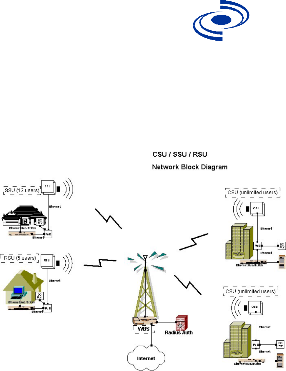
THEORY OF OPERATIONS
KarlNet’s CPE Outdoor wireless devices are used as remote stations that connect to a
base station or repeater, and are used in both point-to-point and point-to-multipoint
networks. They provide low cost, easy to install solutions for small office or large
business locations. The following diagram illustrates how KarlNet’s CPE outdoor
devices are used within the wireless network.

525 Metro Place North, Suite 100
Dublin, OH 43017
Office: 614-822-5275
Fax: 614-822-0024
www.KarlNet.com
8
KarlNet
FEATURES
Software Features Small Office
Subscriber Unit
(SSU)
Corporate Subscriber
Unit (CSU)
Users Supported Limited Unlimited
SNMP Support 3 3
NAT and DHCP 3 3
Password-based Security 3 3
WEP+ Support 3 3
Optional Software
Encryption
No Only products with
suffix “E”
Adaptive Dynamic Polling 3 3
Bandwidth Control/Data
Rate Throttling
3 3
Superpacket Aggregation 3 3
Solution for Hidden Node
Problem
3 3
Routing 3 3
Simple Firewall 3 3
Full Firewall Optional 3
Hardware/Environmental
Features
Operating Temperatures -40C to 85C/-40F to
185F temperature
range, with non-
condensing humidity.
-40C to 85C/-40F to
185F temperature
range, with non-
condensing humidity.
Humidity 95% 95%
FCC Class B 3 3
FCC Part 15 Certified 3 3
Coverage Range Up to 6 Miles Up to 6 Miles
Continuous Signal Quality
Monitoring
3 3

525 Metro Place North, Suite 100
Dublin, OH 43017
Office: 614-822-5275
Fax: 614-822-0024
www.KarlNet.com
9
KarlNet
INSTALLATION
Follow the steps below to install your KarlNet CPE Outdoor wireless device:
1. Mount the unit.
2. Power up the unit.
3. Configure the unit.
4. Align and test the unit.
Each step is described in more detail below.
Mount the Unit
Each SSU or CSU unit ships with a mounting bracket and associated hardware that can
be used to mount the unit on a pole. The bracket should be used on poles that support
standard U-mounts (2.5” in diameter). You can use other mounting brackets at your own
discretion.
General Mounting Considerations
Mount the SSU or CSU to a secured pole in the shade, with unobstructed line of
sight to the Wireless Base Station (WBS).
Stainless steel hose-clamps, or any suitable equivalent, may be used to secure the
unit to the mast.
Leave the unit mounting loose enough to allow for movement when performing
the alignment/testing procedure. The unit should be tightened only after the
alignment/testing procedure is completed.
Power up the Unit
Power for the SSU/CSU is provided either through a Teletronics PoE Injector (or another
approved PoE injector) or through a Jameco 14/15V DC power wall-wart (or another
approved DC power supply). The SSU/CSU ships with both a PoE injector and DC
power supply.
To power the unit:
525 Metro Place North, Suite 100
Dublin, OH 43017
Office: 614-822-5275
Fax: 614-822-0024
www.KarlNet.com
10
KarlNet
1. Run a straight Ethernet coupler and an Ethernet wire (not to exceed 200 feet) to
an indoor wall outlet to the PoE injector and DC power supply (both included
with your SSU or CSU unit).
2. Connect the Ethernet cable to the unit at location “ODU” (OutDoor Unit) on the
PoE injector.
3. Connect a straight Ethernet cable from the “NET” location on the PoE injector to
a hub or switch.
Note: The Ethernet to Ethernet connection at the cable end should be water sealed or
shielded from rain/snow.
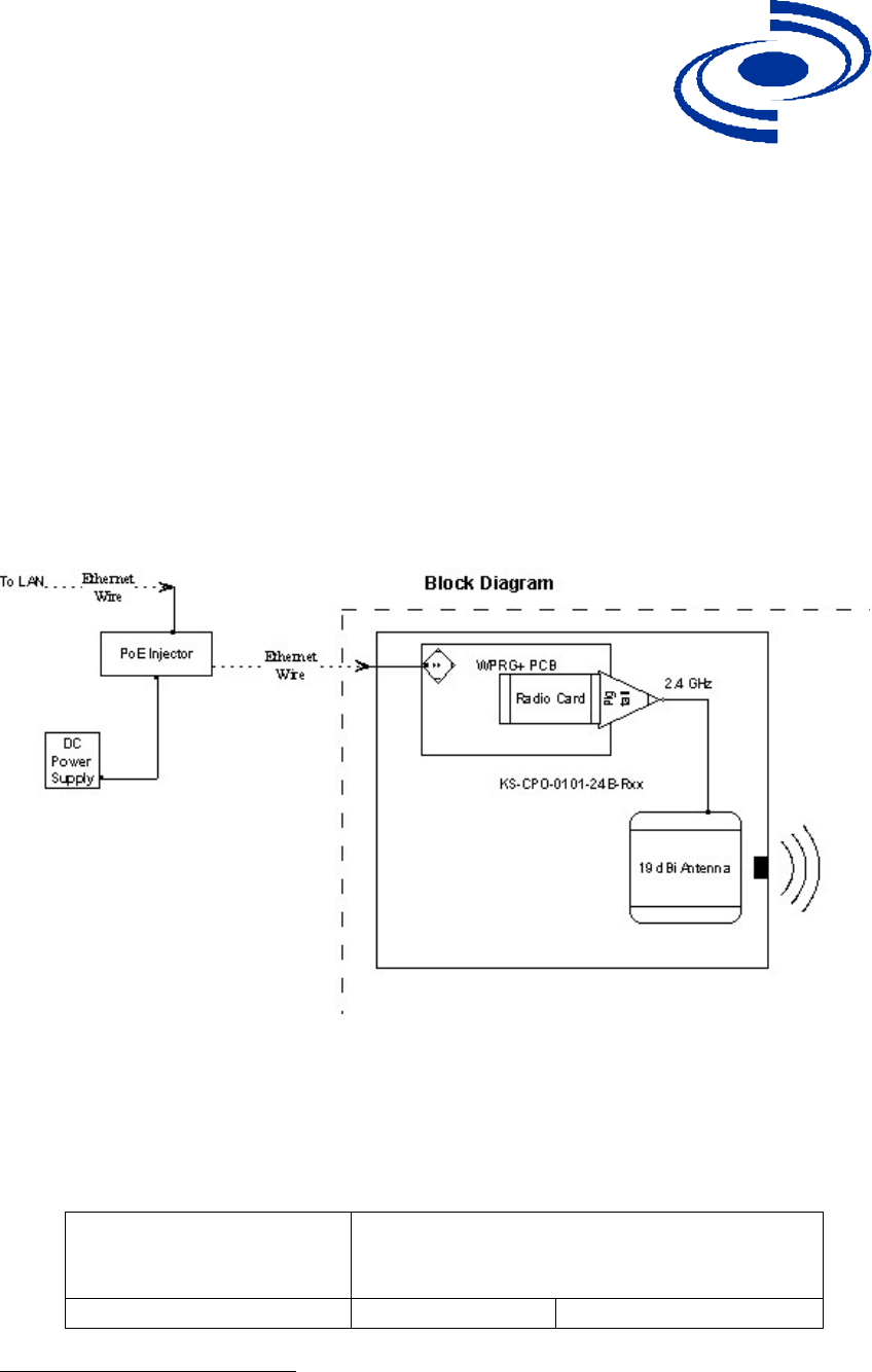
The following diagram illustrates the basic power configuration.
KarlNet CPE Outdoor products operate with the included Power over Ethernet (PoE)
injector. When planning an installation using PoE, it is important to consider the power
requirements of the CPE Outdoor system and the length of the Ethernet cable that will
carry the power. The table shown below specifies the injector specifications required to
deliver power to the CPE Outdoor device over various lengths of Ethernet Cable.
If the Ethernet cable
length is less than or equal
to:
Then the PoE injector1 should be rated for at
least:
0 – 200 ft (0 - 61 m) 14V 11W
1 Included in the SSU/CSU packaging.

525 Metro Place North, Suite 100
Dublin, OH 43017
Office: 614-822-5275
Fax: 614-822-0024
www.KarlNet.com
11
KarlNet
200 – 328 ft (61 – 100 m) Contact KarlNet
Customer Support
Contact KarlNet
Customer Support
Configure the Unit
The KarlNet Kbridge Configurator handles configuration. Both the executable file
needed to launch the Configurator (kbwin.exe) and the online help for the Configurator
(kbwin.chm) are included on the Getting Started disk that you received with your
hardware device. Refer to the online help for instructions on how to configure your
device.
Align and Test the Unit
The KarlBridge Configurator’s Wireless Link Test screen is used to diagnose the wireless
link quality between a WISP Base Station (WBS) and your SSU or CSU unit.
The Wireless Link Test displays the diagnostic counters that apply to the selected
radio interface (Slot A or B) and a single remote station connected to this base
station. To assess the overall wireless performance in the wireless area served by
the base station you might need to run Remote Link Tests with multiple stations (one
by one).
Before Running the Link Test
Your SSU or CSU must be associated with a Wireless Base Station (WBS) before
running the Wireless Link Test. Therefore, before you proceed you must know the
following information about the base station to which you will be linking:
SNMP Read/Write Password
Channel Frequency
Network ID
Network Name
WEP Key (if applicable)
System Access Password
You must now make sure that this information is the same for both your remote unit (the
SSU or CSU) and your WBS.
Note: If you are already familiar with how to associate your remote unit and base
station, skip to the Running the Link Test section.
525 Metro Place North, Suite 100
Dublin, OH 43017
Office: 614-822-5275
Fax: 614-822-0024
www.KarlNet.com
12
KarlNet
To ensure that you have matching information:
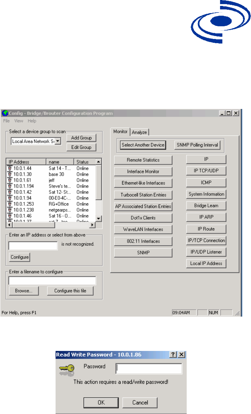
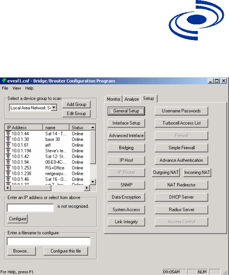
1. Launch the Configurator (file kbwin.exe on your Getting Started CD). The IP
Address for your SSU or CSU (and the IP addresses for any other devices in your
network) appears in the Configurator window, as shown below.
2. Select the IP Address, click the right mouse button, and select Configure This
Device. The Read/Write Password screen is displayed, as shown below.
525 Metro Place North, Suite 100
Dublin, OH 43017
Office: 614-822-5275
Fax: 614-822-0024
www.KarlNet.com
13
KarlNet
3. Enter your SNMP password, then click the OK button. The Configurator window
is redisplayed, this time with the Setup tab highlighted, as shown below.
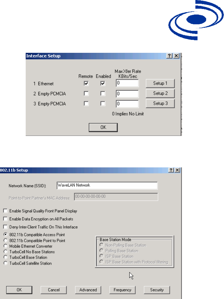
4. Click the Interface Setup button. The Interface Setup screen is displayed, as
shown below:
525 Metro Place North, Suite 100
Dublin, OH 43017
Office: 614-822-5275
Fax: 614-822-0024
www.KarlNet.com
14
KarlNet
5. Click the Setup 2 button. The 802.11b Setup screen is displayed, as shown
below:
6. Click the TurboCell Satellite Station radio button.
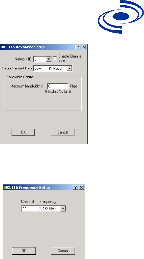
7. Click the Advanced Button. The 802.11b Advanced Setup screen is displayed, as
shown below:
525 Metro Place North, Suite 100
Dublin, OH 43017
Office: 614-822-5275
Fax: 614-822-0024
www.KarlNet.com
15
KarlNet
8. In the Network ID field, select the Network ID that matches your WBS. Then
click the OK button. The 802.11b Setup screen is redisplayed.
9. Click the Frequency button. The Frequency Setup screen is displayed, as shown
below.
10. Select the Channel/Frequency to match your WBS from the dropdown list. Then
click the OK button. The 802.11b Setup screen is redisplayed.
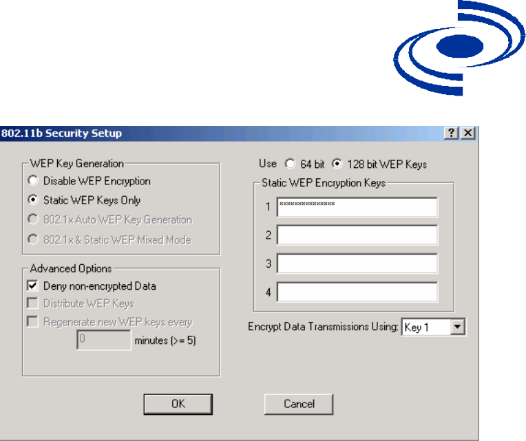
11. If your unit supports encryption (models with suffix “E”), then click the Security
button. The 802.11 Security Setup screen is displayed, as shown below.
525 Metro Place North, Suite 100
Dublin, OH 43017
Office: 614-822-5275
Fax: 614-822-0024
www.KarlNet.com
16
KarlNet
12. The Static WEP Keys Only field is enabled by default. Enter a WEP Encryption
key in one of the four fields on the right side of the screen, then select the
corresponding Key field from the Encrypt Data Transmission Using … dropdown
list. For example, if you enter a key in field 1, then make sure that Key 1 is
selected in the dropdown list. Then click the OK button.
You have now completed the preliminary steps, and you are now ready to run the
wireless link test. Click OK to close the Security window, click Cancel to close the
802.11b Setup screen, and then click OK to close the Interface Setup screen. You should
now be back at the main Configurator window, ready to run the wireless link test.
Running the Link Test
To run a link test:
1. If you have not already done so, launch the Configurator (the file kbwin.exe on
the enclosed “Getting Started” CD), and select Wireless Link Test from the
Analyze Tab. The Enter IP Address screen is displayed, as shown below.

525 Metro Place North, Suite 100
Dublin, OH 43017
Office: 614-822-5275
Fax: 614-822-0024
www.KarlNet.com
17
KarlNet
2. Enter the Remote IP Address and Read/Write password for the wireless station
you wish to test. The Select a Remote Link Partner screen is displayed, as shown
below.
3. From the list of station names, select the remote station or client you wish to test.
Select a station from the list, and then click on the Link Test button to perform a
link test.
Note: Clicking the Explore button refreshes the list of stations that can be
selected.
4. Click the Link Test button to start the link test.
Note: When you open this screen, the base station will need approximately 20
seconds to build the list of stations and forward this information to your
Configurator station. Due to the dynamic characteristics of mobile wireless
stations, the base station will rebuild the list of connected stations each time you
525 Metro Place North, Suite 100
Dublin, OH 43017
Office: 614-822-5275
Fax: 614-822-0024
www.KarlNet.com
18
KarlNet
select a different station, or after clicking the Explore button. If this screen does
not display any station, there might be no wireless station up and running in the
vicinity of the selected base station.
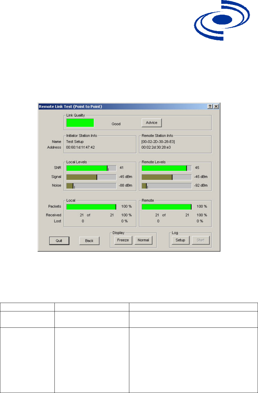
The Remote Link Test screen displays the results of your wireless link test, as shown
below.
5. The Advice button enables you to investigate the outcome of the Remote Link
Test assessment in more detail and provides you with troubleshooting hints to
improve the quality of the link between the two remote nodes. The following
table summarizes the possible results of clicking the Advice button, and what
action is warranted based on the results:
Status Risk Action
Excellent None You do not need to perform further
diagnostics.
Good None Run your radio’s Client Manager
tool (for example, ORiNOCO
Client Manager) and walk
throughout the network
environment. The indicators from
the Site Monitor screens should
enable you to see whether you
could optimize the unit placement.

525 Metro Place North, Suite 100
Dublin, OH 43017
Office: 614-822-5275
Fax: 614-822-0024
www.KarlNet.com
19
KarlNet
You may try to optimize antenna
placement to see whether this will
improve the Link Quality result.
Marginal Communication is still
possible, but this
situation may affect the
unit's
performance.
View Link Test Details to verify.
The unit may have to retransmit lost
packets.
Verify the Signal Level indicator. A
low Signal Level indicates the unit
has moved away from the base
station.
View Link Test Details to verify the
Noise Level indicator. A high Noise
Level indicates a source of
interference in the signal path
between the unit and the base
station.
Select another unit to verify if the
base station is functioning properly.
Try to optimize antenna placement
to improve the Signal Level or
move it away from the source of
interference.
“No
Connection”
Communication is no
longer possible. If the
unit was in the process
of transferring files,
data may not have
arrived at the intended
destination, or
it may have been
corrupted.
View Link Test Details to verify the
Signal Level indicator. A low
Signal Level indicates the unit has
moved away from the base station.
View Link Test Details to verify the
Noise Level indicator. A high Noise
Level indicates a source of
interference in the signal path
between the unit and the base
station.
Select another unit to verify if the
base station is functioning properly.

525 Metro Place North, Suite 100
Dublin, OH 43017
Office: 614-822-5275
Fax: 614-822-0024
www.KarlNet.com
20
KarlNet
Try to optimize antenna placement
to improve the Signal Level or
move it away from the source of
interference.
Quality Indicator
is Black
None. The base station
may be busy collecting
diagnostic measurement
results from
the unit.
If the indicator remains blank, click
the Other button to return to the
Select a Remote Link Partner
screen. Click the Explore button to
refresh the list of Link Test
Partners. If the initial partner no
longer appears, it may have been
switched off, or have been moved
outside the range of the selected
Initiator Station.
Select another Link Test Partner to
verify if the base station is
functioning properly.

525 Metro Place North, Suite 100
Dublin, OH 43017
Office: 614-822-5275
Fax: 614-822-0024
www.KarlNet.com
21
KarlNet
CONTACT
KarlNet, Inc.
525 Metro Place N., Suite 100
Dublin, OH 43017
Office: (614) 822 – 5275 x131
Fax: (614) 822 – 0024
Email: sales@KarlNet.com
Web: http://www.KarlNet.com