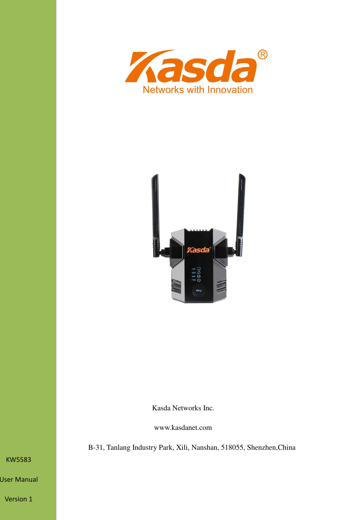
Kasda Networks KW5583 802.11b/g/n wireless repeater User Manual

Kasda Networks inc 802.11b/g/n wireless repeater

User Manual

                                                                                                                                          Kasda Networks Inc. www.kasdanet.com B-31, Tanlang Industry Park, Xili, Nanshan, 518055, Shenzhen,China                        KW5583 User Manual Version 1
                                                                                                               NOTICE This document contains proprietary information protected by copyright, and this Manual and all the  accompanying  hardware,  software,  and  documentation  are  copyrighted.  All  rights  are reserved. No part of this document may be photocopied or reproduced by mechanical, electronic, or other means in any form.  The manufacturer does not warrant that the hardware will work properly in all environments and applications, and makes no warranty or representation, either expressed or implied, with respect to the quality, performance, merchantability, or fitness for a particular purpose of the software or documentation. The manufacturer reserves the right to make changes to the hardware, software, and  documentation  without  obligation  to  notify any  person  or  organization of the revision  or change.  All brand and product names are the trademarks of their respective owners.  Copyright 2014 All rights reserved.
                                                                                                               Content 1. Product Overview .......................................................................................................... 1 1.1 Main Features ............................................................................................................ 1 1.2 Wireless Features ....................................................................................................... 2 1.3 Management Support ................................................................................................ 2 1.4 System Requirements ................................................................................................ 2 1.5 Environmental ........................................................................................................... 2 1.6 Package ...................................................................................................................... 3 2. Product introduction ...................................................................................................... 4 2.1 Hardware Description ............................................................................................... 4 2.2 How the Extender Works........................................................................................... 6 2.3 Connect a PC to the Extender with an Ethernet Cable .............................................. 7 3. Web-based Settings Guide ............................................................................................. 9 3.1 Extender main page configuration .......................................................................... 9 3.1.1    LAN configuration .................................................................................... 10 3.1.2    WAN configuration ................................................................................... 12 3.1.3    Wireless configuration .............................................................................. 14 3.1.4    Administration configuration .................................................................... 17 3.2 Connect the Extender to an Existing Network ........................................................ 21 3.2.1 Connect the Extender to an Existing Network ............................................. 21 3.2.2 Using WPS ................................................................................................... 23
                                                              1                                                                                                         1. Product Overview Thank you for choosing our product. The KASDA Universal WIFI Range Extender  KW5583 effectively  doubles  the  operating  distance  of  your  entire  wireless  network  and  conveniently avoids additional need for power cables or device clutter on your office desk or home theater. KW5583 extends your wireless network to include the area outside the range of your existing wireless router  by overcoming  obstacles and  enhancing overall  network  signal quality,  giving you  the  freedom  to  roam  anywhere  in  the  house  and  access  Internet  without  worrying  about coverage.  The  product  was  specifically  designed  to  be  plugged  into  an  electrical  outlet,  and blends in nicely with any surrounding. It is compatible with wireless b/g/n routers, gateways and Internet service provider devices.   With  300Mbps  wireless  N  speeds,  KW5583  turns  your  ‘dead  zones’  into  connected  zones, helping  you  keep  mobile  devices,  media  players  and  computers  connected  to  Wi-Fi  with  a reliable connection. 1.1 Main Features  Extend Internet access throughout your home for wireless devices like iPads , iPods , laptops, smart phones, game consoles and TVs.  Keep  your  current  equipment  and  improve  coverage  to  eliminate  wireless “dead zones”  Very easy to use.Sets up in minutes, no need to insert a CD or plug in Ethernet cables    Push  ‘N’  Connect— Push  ‘N’  Connect  using  Wi-Fi  Protected  Setup  (WPS) connects computers and/or routers to the Extender quickly and securely  Works  with  any  wireless  b/g/n    router  or  gateway  from  KASDA  and  other brands  Works  with  all  security  standards  including  WPA-PSK,  WPA2-PSK,  mixed mode and WEP  Ethernet port allows the Extender to function as a bridge to connect to home theater devices
                                                              2                                                                                                         1.2 Wireless Features  Fully IEEE 802.11b /g /n compatible.  Wireless data rate up to 300 Mbps  Operating in the unlicensed 2.4 GHz ISM band  Easy wireless security encryption at a push of the WPS button  Supports 64/128 bits WEP, WPA, WPA2, WPA/WPA2-PSK, 802.1x 1.3 Management Support  Web Based GUI  Upgrade or update via FTP/HTTP  Command Line Interface via Telnet  Firmware upgrade-able for future feature enhancement 1.4 System Requirements  802.11 b/g/n 2.4 GHz wireless router or gateway  802.11 b/g/n 2.4 GHz wireless adapter or Ethernet adapter and cable for each computer  Microsoft® Windows 7, Windows 8, Vista®, XP®, 2000, Mac OS®, UNIX®, or Linux®  Microsoft® Internet Explorer® 5.0, Firefox® 2.0 or Safari® 1.4 or higher 1.5 Environmental  Operating temperature: 32° to 140° F (0° to 40° C)  Operating Humidity:10% ~ 90% RH non-condensing;    Storage Humidity: 5% ~ 90%RH non-condensing.
                                                              3                                                                                                         1.6 Package  KW5583            ×1  CD                ×1
                                                              4                                                                                                         2. Product introduction 2.1 Hardware Description  The LEDs on the front panel show how the Extender is working:   LED Color Function  PWR  Green Off: Power Not Supplied On: Power Supplied LAN  Green On: LAN link established and active via LAN port Blinking: ADSL data activity occurs Off: No LAN link via LAN port       WIFI  Green On: The wireless module is ready and idle   Blinking: Data transmitting or receiving over  WLAN Off: The wireless function is off
                                                              5                                                                                                            WPS button: Press the WPS button to wirelessly connect the Extender to your router or wireless adapter. The side panel has the following feature: Reset: Factory Reset button. To use this button, stick a paper clip into the reset hole and hold it until the Status LED flashes. The down panel has the following feature:  Ethernet Port. You can use this for a wired connection to a computer or other device as described in the User Manual.  Note: When using extender, forr best performance, position antennas pointing up.  WPS Green On: There is wireless security (WPA or WPA2). Blinking: Trying to establish a WPS connection Off: WPS function is off or no WPS connection
                                                              6                                                                                                         2.2 How the Extender Works The Extender works like a bridge between a wireless router and a computer or wireless device outside the wireless router’s range. To do this, the Extender has two main jobs: 1.  The  Extender  connects  to  a  wireless  network  that  is  up  and  running.  When  the  Extender connects wirelessly to a network, it acts as a network client. This is similar to how a computer connects to a network.   2.    The Extender acts as an access point for computers.   In  its  role  as  an  access  point,  the  Extender  performs  tasks  that  wireless  routers  do,  such  as broadcasting its network name (SSID).  Range Extender in a home
                                                              7                                                                                                         When to Use Your Extender? KASDA  recommends  that  you  connect  to  the  Extender  only  when  your  home  network connection is poor. Because data traffic routed through the Extender is inherently slower than traffic  routed  directly  from  the  network,  the  computer  should  stay  on  the  network  if  the connection  is  good  enough.  KASDA  recommends  that  you  connect  through  the  Extender network only when the computer is in a “dead zone” where connection from the network is very poor or non-existent. The  ideal  location  to  place  the  Extender  is  half-way  between  your  wireless  router  and  your computer.  Range extender location The best connection is established when there is a clear line of sight between the Extender and the wireless router and also a clear line of sight between the Extender and the computer you are using. If this straight path is blocked by a thick wall or other materials, move the Extender to a different  location  half-way  between  the  computer  and  the  router.  If  there  is  no  power  outlet nearby, or you prefer to place the Extender elsewhere, move the Extender closer to the computer.   2.3 Connect a PC to the Extender with an Ethernet Cable Usually, you connect to the Extender wirelessly, but you can use its LAN port to connect a wired device such as an Ethernet-enabled gaming console, printer, or PC.
                                                              8                                                                                                         1.    Connect your computer to the Extender with an Ethernet cable. 2.    Plug the Extender into an electrical outlet. 3.    Log in as described in the following section.  CAUTION: Do not use Ethernet cable to connect the Extender to a router. If you do so, the Extender does not work because it is designed to use only a wireless connection to the router. If you have trouble connecting    Make  sure  you  use  a  computer  that  occupies  the  same  subnet  with  the  Extender.    The simplest way to do this for many users will be to use DHCP server that is enabled by default on the Extender.  If  you  start  your  computer,  connect  the  Ethernet  cable  to  the  Extender,  and  launch  your browser quickly, the computer might still need a couple of minutes to recognize the Ethernet LAN connection before you can connect.    Make sure that your Ethernet cable is securely connected to the Extender and the computer, and that the Extender LAN LED is on. If the LED is not lit reconnect the Ethernet cable, and relaunch your Internet browser. 1. On your computer, launch an Internet browser such as Mozilla Firefox or Microsoft Internet Explorer. 2. In the  address field  of  your browser,  enter  192.168.0.1. You  are prompted  to  enter  a user name and password. They are: admin & admin. Now you can configuration your extender. You can  log  in  to  the  Extender  to  use  the  menu  selections  to  view  or  change  the  extender’s settings.
                                                              9                                                                                                         3. Web-based Settings Guide   To change settings, connect the Extender to your computer and use your Internet browser to go to http://192.168.0.1 described in Connect a PC to the Extender with an Ethernet Cable. 3.1 Extender main page configuration When  using  http://192.168.0.1 to  log  on  to  the  setting  pages.  Enter  username  “admin”  and password “admin”, then click “OK”.   You will see the following page. The Status page displays the Router's current status and wan configuration.  This page show the router local, Ethernet network.  If you are using the Router as a DHCP server, that will be displayed here.  Click OK  Enter  username  ‘admin’ and password ‘admin’
                                                              10                                                       These are the current settings or information for Wireless. You can configure them in the Wireless -> Basic Settings page.  3.1.1  LAN configuration You can configure the IP parameters of LAN on this page.
                                                              11                                                       Router IP Local IP Address / Subnet Mask: This is the router IP Address and Subnet Mask as seen on the internal LAN. The default value is 192.168.0.1 for IP Address and 255.255.255.0 for Subnet Mask.  Network Address Server setting(DHCP) DHCP Server – Keep the  default, Enable, to  enable the router's DHCP server option.  If  you already have a DHCP server on your network or you do not want a DHCP server, then select Disable. Start IP Address:Specify an IP address for the DHCP Server to start with when assigning IP addresses. 192.168.0.100 is the default start address.   Maximum number of Users – Enter the maximum number of PCs that you want the DHCP server to assign IP addresses to. The absolute maximum is 253, possible if 192.168.1.2 is your starting IP address. Client Lease Time – Enter the length of time, in minutes, that a DHCP client will be allowed to use a dynamic IP address. The default is 0 minutes, which means one day. After this time is up, the client will be automatically assigned a new dynamic IP address, or the lease will be renewed.
                                                              12                                                     Note:   1) If  you  change  the  IP  Address  of  LAN,  you  must  use  the  new  IP  Address  to log  in  the extender.   2) If the new LAN IP Address you set is not in the same subnet, the IP Address pool of the DHCP server will change accordingly at the same time.   3.1.2    WAN configuration  The  router  supports  several  connection  types  to  WAN  (wide  area  network).These  types  are selected  from  the  dropdown  menu  beside  WAN  Connection  Type.  The  setting  fields  differ depending on the connection type you selected.  WAN Connection Type (1)   Automatic Configuration – DHCP If  you  connect  using  a  dynamic  IP  address  or  cable modem,  keep the  default:  Automatic Configuration - DHCP.
                                                              13                                                      Host Name (Optional) – Enter a host name for the extender, if required by your ISP. Domain Name (Optional) – Enter a domain name for the extender, if required by your ISP. MTU – MTU is the Maximum Transmission Unit. It specifies the largest packet size permitted for Internet transmission. Keep the default setting, Auto, to have the router select the best MTU for your Internet connection. To specify a MTU size, select Manual, and enter the value desired (default is 1400). You should leave this value in the 1200 to 1500 range. (2) Static IP . To use a fixed IP address to connect to the Internet, select Static IP.  Internet IP Address – Enter the IP address provided by your ISP. Subnet Mask – Enter the subnet mask provided by your ISP.
                                                              14                                                     Default Gateway – Enter the gateway IP address provided by your ISP. DNS 1-3 – Enter the DNS (Domain Name System) server IP address(es) provided by your ISP. 3.1.3    Wireless configuration    Wireless basic settings  Use the Guest Access feature to provide guests visiting your home with Internet access only. The guest network is a wireless network separate from your local network.       •    Allow Guest Access – To allow Internet access through a guest network, select yes.   •    Guest Network Name – The name of the guest network is displayed.  •   SSID Broadcast – When wireless devices survey the local area for wireless networks to associate with, they will detect the SSID (wireless network name) broadcast by the Router. To broadcast the SSID of the guest network, keep the default, Enabled. You can select one of the following security options:  •    Disabled  –  The  wireless  security  function  can  be  enabled  or  disabled.  If  disabled,  the
                                                              15                                                     wireless  stations  will  be  able  to  connect  the  Router  without  encryption.  It  is  recommended strongly that you choose one of following options to enable security.  •    WEP – Select 802.11 WEP security.  •    WPA/WPA2 - Personal – Select WPA based on pre-shared passphrase.  •    WPA/WPA2 - Enterprise – Select WPA based on Radius Server. Each security option has its own settings as described follows.        WEP     Select a level of WEP encryption.     •    Passphrase  – Enter a passphrase to automatically generate WEP keys. Then click Generate.     •    Key 1 – If you did not enter a passphrase, enter the WEP key(s) manually.  WPA/WPA2       Version - You can select one of following versions,     •    WPA – Wi-Fi Protected Access.    •    WPA2 – WPA version 2.    •    RADIUS Server – Enter the IP address of the RADIUS server.    •    RADIUS Port – Enter the port number of the RADIUS server. The default is1812.    •    Shared Key – Enter the key shared between the Router and the server.    WPA-PSK/WPA2-PSK Version - You can select one of following versions,     •    WPA-PSK – Pre-shared key of WPA.     •    WPA2-PSK – Pre-shared key of WPA2.
                                                              16                                                        PSK Password –You can enter ASCII or Hexadecimal characters. For Hexadecimal, the length should be between 8 and 64 characters; for ASCII, the length should be between 8 and 63 characters.  Wireless settings  •    Channel  –  This  field  determines  which  operating  frequency  will  be  used.  It  is  not necessary to change the wireless channel unless you notice interference problems with another nearby access point. If you select auto, then AP will choose the best channel automatically.  •    Bandwidth – The bandwidth of the wireless channel.  WPS configuration
                                                              17                                                      WPS function will help you add a new device to the network quickly. If the new device supports Wi-Fi Protected Setup and is equipped with a configuration button, you can add it to the network by pressing the configuration button on the device and then press the button on the Router within two minutes. The status LED on the Router will light blue for five minutes if the device has been successfully added to  the  network.  If the  new device  supports  Wi-Fi Protected Setup  and  the connection way using PIN, you can add it to the network by entering the Router's PIN. •    WPS Status – Enable or disable the WPS function here. •    Push Button – This button's function is same to the physical button on the router. 3.1.4    Administration configuration  Time setting This  page  allows  you  to  set  the  time  manually  or  to  configure  automatic  time synchronization.  The  Router  can  automatically  update  the  time  from  an  NTP  server  via  the Internet.
                                                              18                                                       Time Zone - Select your local time zone from this pull-down list.  Time  Servers  -  Select  the  time  servers.You  can  choose  the  place  where  you  are.Or  select Custom to configure the servers by yourself. Note: After you have made your changes, Click Save to apply the changes.  Password:  It is strongly recommended that you change the factory default user name and password of the Router.  All  users  who  try  to  access  the  Router's  web-based  utility  will  be  prompted  for  the
                                                              19                                                     Router's user name and password.  Backup/restore/reset  Click  the  Backup  button  to  save  all  configuration  settings  to  your  local  computer  as  a file.  Click the Browse button to find the configuration file which you want to restore.  Click the Upload button to update the configuration with the file whose path is the one you have input or selected in the blank. Click the Reset Defaults button to reset all configuration settings to their default values.   The default User Name: admin   The default Password: admin     The default Subnet Mask: 255.255.255.0
                                                              20                                                          You can also press and hold the Reset button on the side panel for 6 seconds. The Extender resets, and returns to its factory settings. 1.  Maximum  wireless  signal  rate  (IEEE  Standard  802.11).  Actual  throughput  will  vary. Network  conditions  and  environmental  factors,  including  volume  of  network  traffic,  building materials and construction, and network overhead, lower actual data throughput rate.   Note: All changed settings will be lost when defaults are restored.    Firmware update   Click Browse/Choose and select the firmware upgrade file. Then click Start Upgrade. Factory settings   Wireless Wireless    communication   enabled Wireless Network name(SSID)  Security disabled Transmission speed Auto1 Operating mode 802.11n, 802.11g, 802.11b Data rate Up to 300Mbps
                                                              21                                                     Warning: Upgrading firmware may take a few minutes; please don't turn off the power or press the reset button. Upgrade must not be interrupted!! 3.2 Connect the Extender to an Existing Network 3.2.1 Connect the Extender to an Existing Network Here you can use quick setup page to connect the Extender to an Existing Network. This page will guide you through the process step by step configuration wireless extensions. Step 1: Click the start button to search for available near the SSID.  Step 2: After completion of the progress bar will automatically jump to the next screen, please wait around 30s. Step 3: Select the SSID in the table you need as the primary SSID.   Its security mode will be filled in the Security Mode list, please input password that you have selected. And then click next.
                                                              22                                                        Step  4:  In  the  second  SSID  corresponding  box  enter  your  SSID.  In  the  corresponding  box password enter the password you set. Click Apply button to complete the setting.  Step 5: You have completed all set! It is to set up the connection for you, please wait for 1 to 2 minutes. Set up automatically jump to the main interface as below if the connection is successful.
                                                              23                                                      3.2.2 Using WPS   WPS  (Wi-Fi  Protected  Setup)  lets  you  connect  a  wireless  device  to  the  Extender’s  network without entering the wireless network passphrase or key. Instead, you use a WPS button or enter a PIN to connect. WPS supports WPA and WPA2 wireless security. If your Extender network is open (no wireless security is set), then connecting with WPS automatically sets WPA2 + WPA wireless security on the Extender network. To use the Extender WPS button to connect: 1. Locate the WPS button on the side of the Extender. 2.    Press the Extender’s WPS button for 2 minutes, the Extender attempts to add a wireless client (a wireless device) to its wireless network. 3.    Within 2 minutes, press the WPS button on  your wireless device, or follow the WPS instructions that came with your wireless device. Your wireless device is now connected to the Extender.
RF Exposure Information and Statement   This equipment complies with FCC/IC radiation exposure limits set forth for an uncontrolled environment. This equipment should be installed and operated with minimum distance of 20 cm between the radiator and your body. This transmitter must not be co-located or operating in conjunction with any other antenna or transmitter.  This device complies with part 15 of the FCC rules and Industry Canada licence-exempt RSS standard(s). Operation is subject to the following two conditions: (1) this device may not cause harmful interference, and (2) this device must accept any interference received, including interference that may cause undesired operation.  Le présent appareil est conforme aux CNR d'Industrie Canada applicables aux appareils radio exempts de licence. L'exploitation est autorisée aux deux conditions suivantes :   (1) l'appareil ne doit pas produire de brouillage, et (2) l'utilisateur de l'appareil doit accepter tout brouillage radioélectrique subi, même si le brouillage est susceptible d'en compromettre le fonctionnement.  NOTE:  The manufacturer is not responsible for any radio or TV interference caused by unauthorized modifications to this equipment. Such modifications could void the user’s authority to operate the equipment. NOTE: This equipment has been tested and found to comply with the limits for a Class B digital device, pursuant to part 15 of the FCC Rules.   These limits are designed to provide reasonable protection against harmful interference in a residential installation.  This equipment generates uses and can radiate radio frequency energy and, if not installed and used in accordance with the instructions, may cause harmful interference to radio communications.  However, there is no guarantee that interference will not occur in a particular installation.  If this equipment does cause harmful interference to radio or television reception, which can be determined by turning the equipment off and on, the user is encouraged to try to correct the interference by one or more of the following measures: - Reorient or relocate the receiving antenna. - Increase the separation between the equipment and receiver. -Connect the equipment into an outlet on a circuit different from that to which the receiver is connected. -Consult the dealer or an experienced radio/TV technician for help - This device and its antenna(s) must not be co-located or operating in conjunction with any other antenna or transmitter.  (i) Ce dispositif doit être installé et exploité dans une enceinte entièrement fermée afin de prévenir les rayonnements RF qui pourraient autrement perturber la navigation aéronautique. L’installation doit être effectuée par des installateurs qualifiés, en pleine conformité avec les instructions du fabricant.    (ii) Ce dispositif ne peut être exploité qu'en régime de non-brouillage et de non-protection, c’est-à-dire que l’utilisateur doit accepter que des radars de haute puissance de la même bande de fréquences puissent brouiller ce dispositif ou même l’endommager. D’autre part, les capteurs de niveau à propos desquels il est démontré qu’ils perturbent une exploitation autorisée par licence de fonctionnement principal doivent être enlevés aux frais de leur utilisateur.

Navigation menu