Kasda Networks KW5813 ADSL2+ 802.11b/g/n 4 port Managed Switch Router User Manual KE318EU
Kasda Networks inc ADSL2+ 802.11b/g/n 4 port Managed Switch Router KE318EU
UserManual.wiki
>
Kasda Networks
>
KW5813 User Manual
Users Manual
Navigation menu
Upload a User Manual
Namespaces
Wiki Guide
HTML
PDF
Info
Views
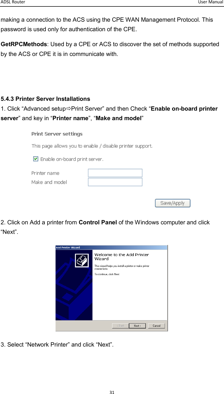
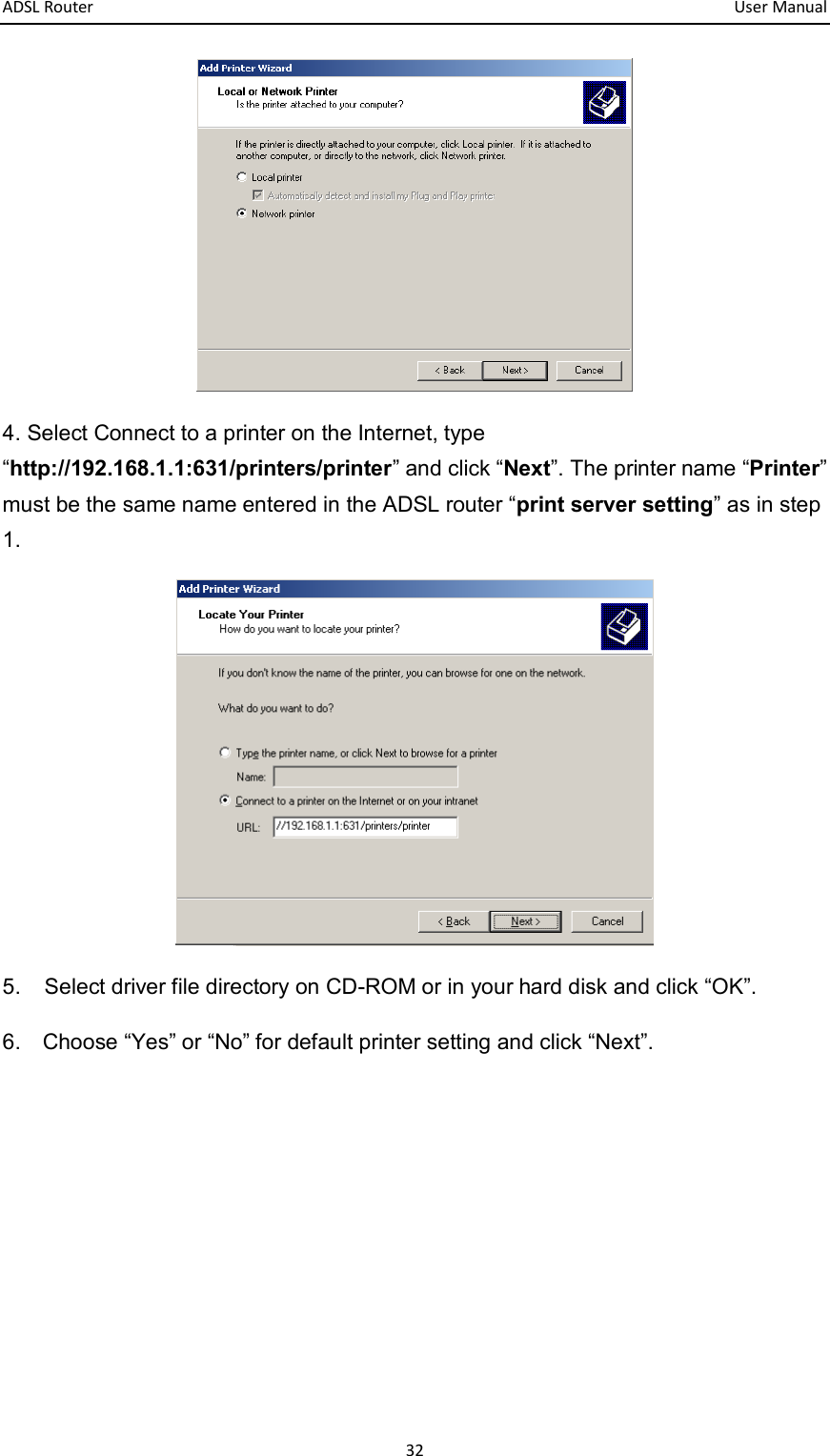
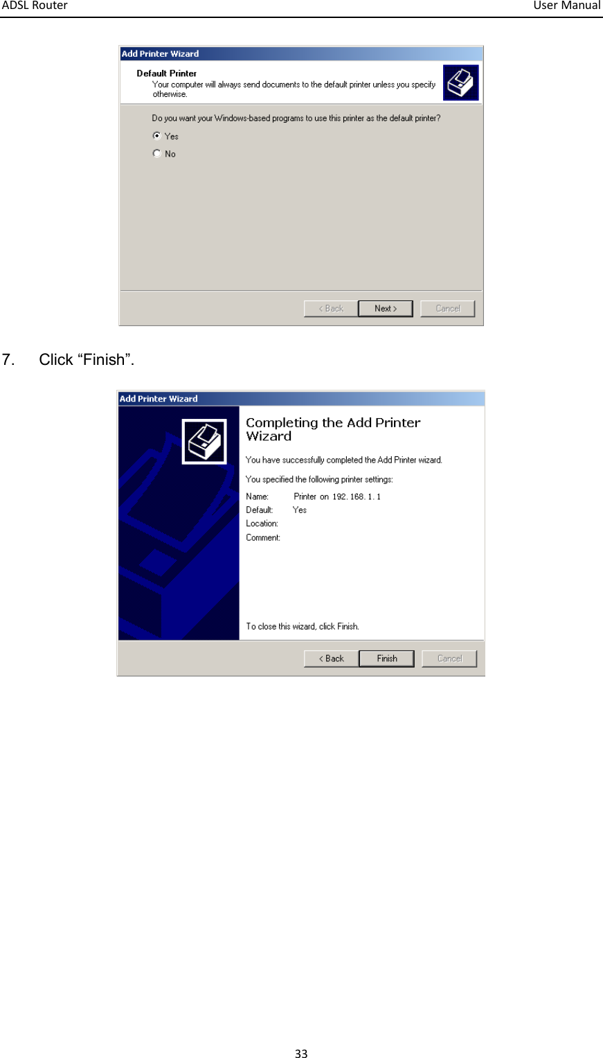
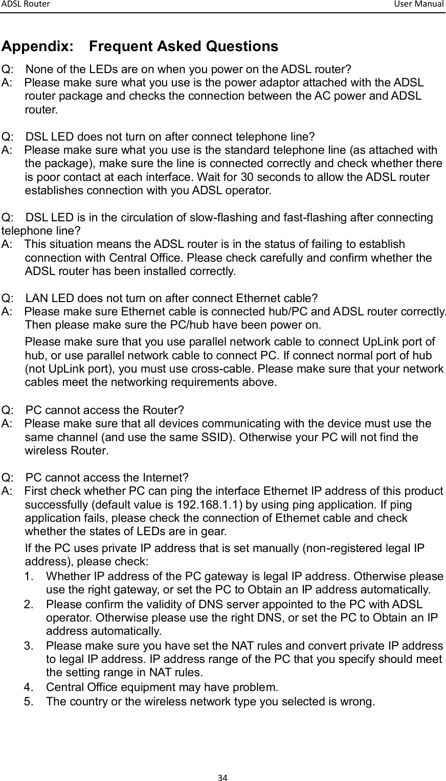
User Manual
Discussion / Help
Navigation