Kathrein Universal Feed Systems Uas 177 Users Manual 9362681c, Speisesystem Mit 1 Ausgang
UAS 177 to the manual b7f62b66-131e-40fe-8e9d-72d1d237aee1
2015-02-09
: Kathrein Kathrein-Universal-Feed-Systems-Uas-177-Users-Manual-567759 kathrein-universal-feed-systems-uas-177-users-manual-567759 kathrein pdf
Open the PDF directly: View PDF ![]() .
.
Page Count: 6
936.2681/C/0906/1.6def
Universal-Speisesystem
mit 1 Ausgang
Polarisation linear, orthogonal umschaltb.
Frequenzbereich umschaltbar
1 x 10,70-11,70 GHz
1 x 11,70-12,75 GHz
Universal feed system
with 1 output
Linear Polarisation, orthogonal (switch.)
Frequency range (switchable)
1 x 10.70-11.70 GHz
1 x 11.70-12.75 GHz
Tête SHF universelle
avec 1 sortie
Polarisation linéaire, orthogonal comm.
Gamme de fréquences, commutables
1 x 10,70-11,70 GHz
1 x 11,70-12,75 GHz
Speisesystem für Kathrein-Offset-Parabolantennen Typ CAS…
(57, 75, 90, 120, 180 cm Ø).
Für den Empfang der Satelliten ASTRA, EUTELSAT (Hot Bird),
TELECOM und Türksat.
Das Speisesystem UAS 177 ist nach Definition des Amtsblattes
Nr. 61, Verfügung BMPT 105/1990 der Deutschen Bundespost eine
Satelliten-Empfangseinrichtung der Kategorie B und entspricht
der ASTRA-Spezifikation für Universal-LNB (ein Ausgang).
Komplettschutz von LNB und Kabelanschlüssen im belüfteten
Gehäuse, Schutzart IP 54
Feed system for Kathrein offset dish antennas type CAS…
(57, 75, 90, 120, 180 cm Ø).
For reception of the satellites ASTRA, EUTELSAT (Hot Bird),
TELECOM and Türksat.
The feed system UAS 177 complies with the requirements set forth in
the Official Gazette No. 61 Directive BMPT 105/1990 and corresponds
to the ASTRA specifications for universal LNBs (single output).
Full protection of LNB and cable connections in vented housing,
protection class IP 54
Tête SHF pour des antennes paraboliques Offset Kathrein types
CAS… (57; 75; 90; 120; 180 cm Ø).
Pour la réception des satellites ASTRA, EUTELSAT (Hot Bird),
TELECOM et Türksat.
La tête UAS 177 répond aux spécifications imprimées dans le bulletin
municipal No. 61 BMPT 105/1990 ainsi qu’aux spécifications ASTRA
pour LNB universelle (une sortie).
Protection totale pour LNB et les câbles dans un boîtier ventilé,
catégorie de protection IP 54
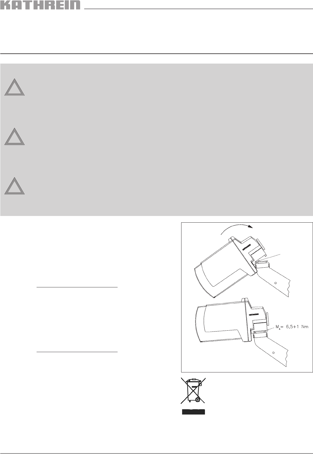
Speisesystem-Montage (Abb. 1)
Mounting the feed system (Fig. 1)
Montage de la tête (Illustr. 1)
Abb. / Fig. / Illustr. 1
UAS 177
268105
Hinweise, Sicherheits- und Gefahrenhinweise
Das Speisesystem UAS 177 darf ausschließlich an die aufgeführten Kathrein-Parabolantennen montiert werden.
Für das Speisesystem gelten die gleichen Sicherheits- und Gefahrenhinweise, wie sie in den
Anwendungshinweisen der Offset-Parabolantennen aufgeführt sind.
Bitte beachten Sie unbedingt diese Hinweise, es könnten sonst Gefahren für Sie oder Ihre Mitmenschen
auftreten (Stromschlag durch Freileitungen, Absturzgefahr, herabfallende Teile, Gewitter etc.).
Notes, security advice and danger warnings
The feed system UAS 177 is exclusively intended for use with the mentioned Kathrein parabolic antennas.
The same notes on safety and dangers as set forth in the user guides for parabolic offset antennas are also valid for the
feed system.
It is absolutely necessary to observe those notes, otherwise risks of injury to you or other persons cannot be excluded
(electric shocks from overhead power lines, falling down, falling objects, thunderstorms, etc.)
Remarques, avis de sécurité et de danger
La tête SHF modèle UAS 177 est désignée exclusivement pour être utilisée avec les antennes paraboliques Kathrein
mentionnées.
Les mêmes conseils de sécurité et de danger comme continus dans les notices pour les antennes paraboliques offset,
sont aussi valables pour la tête SHF.
Observez obligatoirement ces conseils, autrement des dangers pour vous et autre personne ne peuvent être exlcus
(chargement d’électricité par des lignes aériennes, risques de chute, objets tombants, orage, etc.)
Hier ansetzen
insert here
introduire ici
!
Achtung
Gefahr
!
Achtung
Danger
!
Achtung
Danger
Elektronische Geräte gehören nicht in den Hausmüll,sondern müssen -
gemäß Richtlinie 2002/96/EG DES EUROPÄISCHEN PARLAMENTS UND
DES RATES vom 27. Januar 2003 über Elektro-und Elektronik-Altgeräte
fachgerecht entsorgt werden.
Bitte geben Sie dieses Gerät am Ende seiner Verwendung zur Entsor-
gung an den dafür vorgesehenen öffentlichen Sammelstellen ab.
Electronic equipment is not household waste – in accordance with directive
2002/96/EC OF THE EUROPEAN PARLIAMENT AND THE COUNCIL of 27th
January 2003 on used electrical and electronic equipment, it must be
disposed of properly.
At the end of its service life, take this unit for disposal at a relevant official
collection point..
Les appareils électroniques ne doivent pas être mis dans la poubelle de la
maison, mais doivent être recyclés correctement selon la directive
2002/96/EG DU PARLEMENT ET DU CONSEIL EUROPEEN du 27 janvier
2003 concernant les appareils électroniques et électriques usagés.
Nous vous prions de mettre cet appareil à la fin de son utilisation dans un
emplacement prévu pour son recyclage.
936.2681/C/0906/2.6def
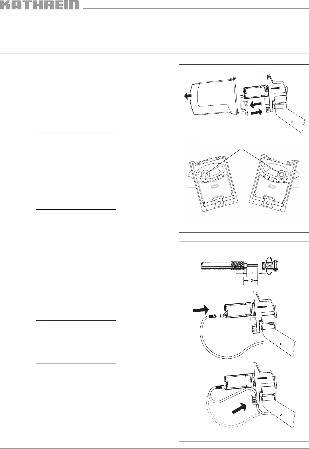
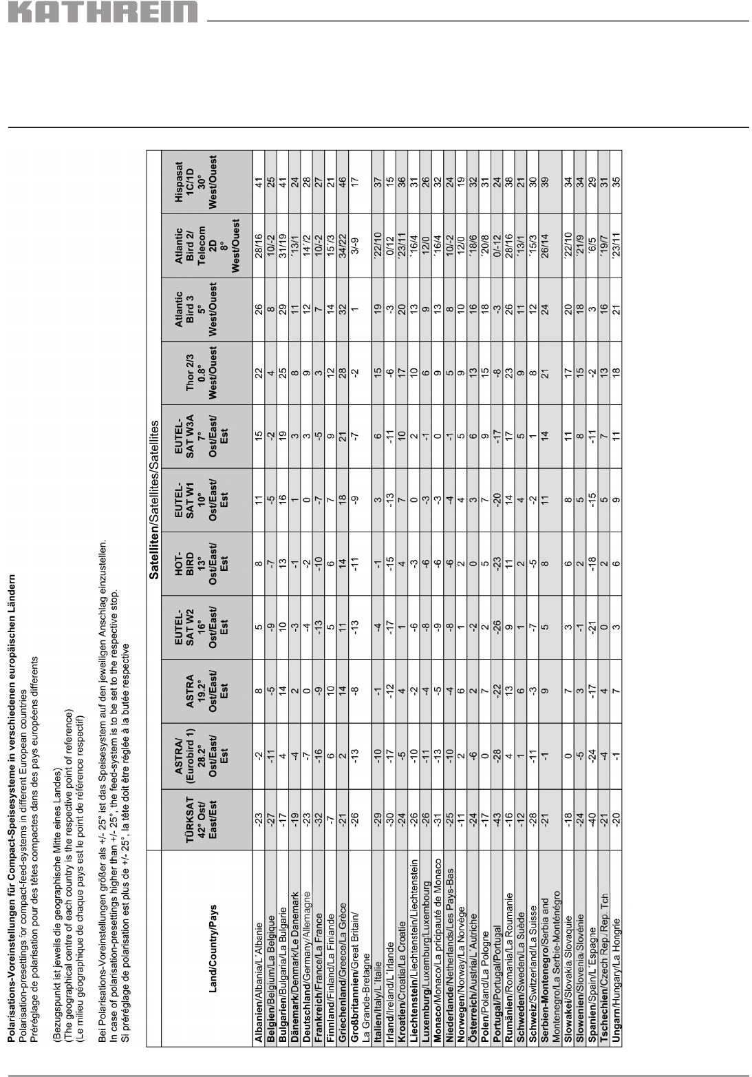
Polarisations-Voreinstellung (Abb. 2)
1. Haube abmontieren.
2. Wert für die Polarisationsv-Voreinstellung aus Tabelle Seite 6
entnehmen. Bei abweichendem Wert von den voreingestellten
0° ist wie folgt zu verfahren:
3. Kombiteil-Dichtelement und Kabelhalter herausziehen.
4. Innensechskantschraube S
lockern und durch Drehen des
Speisesystems den Wert lt. Polarisations-Voreinstellungs-
Tabelle einstellen. Anziehdrehmoment: max. 6 Nm.
5. Kombiteil-Dichtelement und Kabelhalter bis auf Anschlag
eindrücken.
Setting the polarisation (Fig. 2)
1. Remove the cover from the feed system.
2. Refer to the table on page 6 to learn the value for the polarisation-
presetting. If the value differs from the preset 0°, proceed as
follows:
3. Pull out the sealing element and also the cable support.
4. Loosen the hex socket head screw S
and set the value according
to the enclosed table by turning the feed system.
Torque max. 6 Nm.
5. Push in the sealing element and the cable support as far as it will
go.
Ajustage de la polarisation (Fig. 2)
1. Enlever le capot de la tête SHF.
2. Relever la valeur d’ajustage de polarisation du tableau livré avec la
tête (voir page 6). Au cas où la valeur est différente de la valeur
préajustée de 0°, procéder comme suit:
3. Tirer l’élément d’etanchéité ainsi que le support de câbles hors de
la partie-combi.
4. Desserrer l’écrou à six pans S
, ajuster la valeur indiquée dans la
tableau en tourant la tête SHF.
5. Repousser jusqu’à l’arrêt l’élément d’étanchéité ainsi que le support
de câble
Kabelanschluss (Abb. 3)
1. Beiliegenden F-Stecker auf Kathrein-Kabeltyp LCD 95,
LCD 99 oder LCD 111 montieren und am LNB anschließen.
2. Angeschlossenes Kabel in den Kabelhalter eindrücken.
Cable connection (Fig. 3)
1. Connect the enclosed F connectors to the Kathrein cables
LCD 95, LCD 99 or LCD 111.
Then connect it to the LNB as shown on the sticker.
2. Push the connected cable into the cable support.
Raccordement (Illustr. 3)
1. Raccorder le connecteur F avec les câbles Kathrein types
LCD 95, LCD 99 ou LCD 111 comme demontré et raccorder les
mêmes avec le LNB.
2. Ensuite fixer le câble dans le support de câble.
O
S
+ 15° - 15°
Geflecht zurückgelegt
Braiding overturned
Tressage retroussé
Abb. / Fig. / Illustr. 2
Abb. / Fig. / Fig. 3
936.2681/C/0906/3.6def
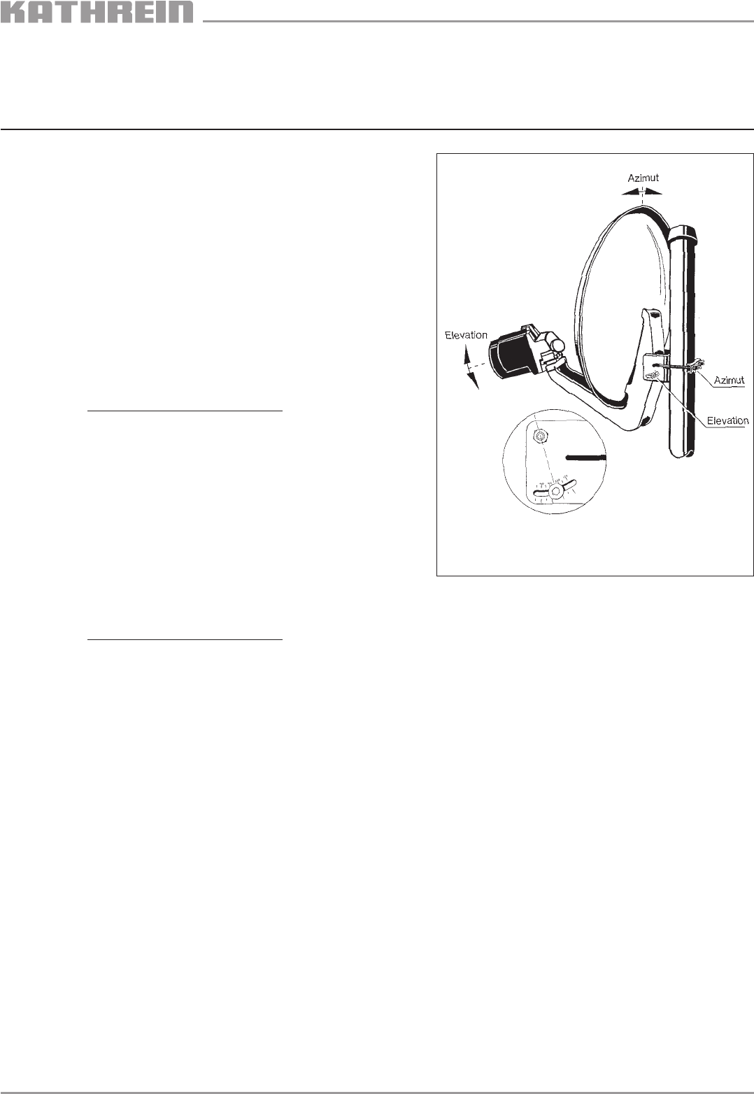
Ausrichten der Satellitenempfangsanlage (Abb. 4)
1. Grundeinstellung nach beiliegender Azimut-/Elevationstabelle
vornehmen.
2. Durch Drehen über die Azimut-Achse Sender suchen
(siehe beiliegende Frequenztabelle) und auf Maximalanzeige
einstellen (bei Verwendung eines Kathrein-Satelliten-Mess-
empfängers MSK..).
Steht kein Messgerät zur Verfügung, auf beste Bildqualität
einstellen (siehe Abb. 5 und Text).
3. Elevation auf Maximalanzeige bzw. beste Bildqualität
einstellen.
4. Azimut-Einstellung überprüfen und gegebenenfalls
nachjustieren.
5. Alle Befestigungsteile auf vorgeschriebenes Drehmoment MA
festdrehen. (Siehe Montageanleitung der Parabolantenne)
6. Nach den Anschluss- und Einstellarbeiten Abdeckhaube
wieder aufsetzen und festschrauben.
Aligning the satellite reception system (Fig. 4)
1. The basic alignment is to be effected acc. to the
Azimuth/Elevation table.
2. Now Search for a satellite programm (see enclosed frequency table)
by turning the antenna around the azimuth axle until max. signal
strength is reached (if a Kathrein signal meter MSK is used) or until
best picture quality is obtained if no signal meter is at hand.
3. Set the elevation acc. to max. signal level or best picture quality.
4. Check the Azimuth alignment and readjust if necessary.
5. All fixing elements must now be screwed tightly in conformity with the
torque moment MA (see mounting instructions for the parabolic
antenna).
6. After having finished the alignment, but back the cover of the feed
system and screw it tightly.
Positionnement de l’antenne satellite (Illustr. 4)
1. Procéder à alignement de l’antenne selon le tableau
Azimut/Elévation livré avec la tête.
2. Rechercher un programme satellite (voir tableau de fréquence livré
avec la tête) en tournant l’antenne autour de son axe Azimut
jusqu’on a trouvé le niveau le plus élévé (en cas d’utilisation d’un
mesureur de champ satellite Kathrein (MSK…) où jusqu’à l’on a ob-
tenu la meilleure image (alignement sans mesureur de champ satel-
lite).
3. Ajuster maintenant l’élévation à l’aide du niveau le plus élévé ou
selon la meilleure image.
4. Contrôler l’alignement Azimut et réajuster si nécessaire.
5. Serrer tous les éléments de fixation conforme au moment de tor-
que MA prescrit (voir avis de montage pour l’antenne parabolique).
6. Après avoir terminé tous les travaux mentionnés
ci-dessus, remettre le capot et serrer.
Abb. / Fig. / Illustr. 4
936.2681/C/0906/4.6def
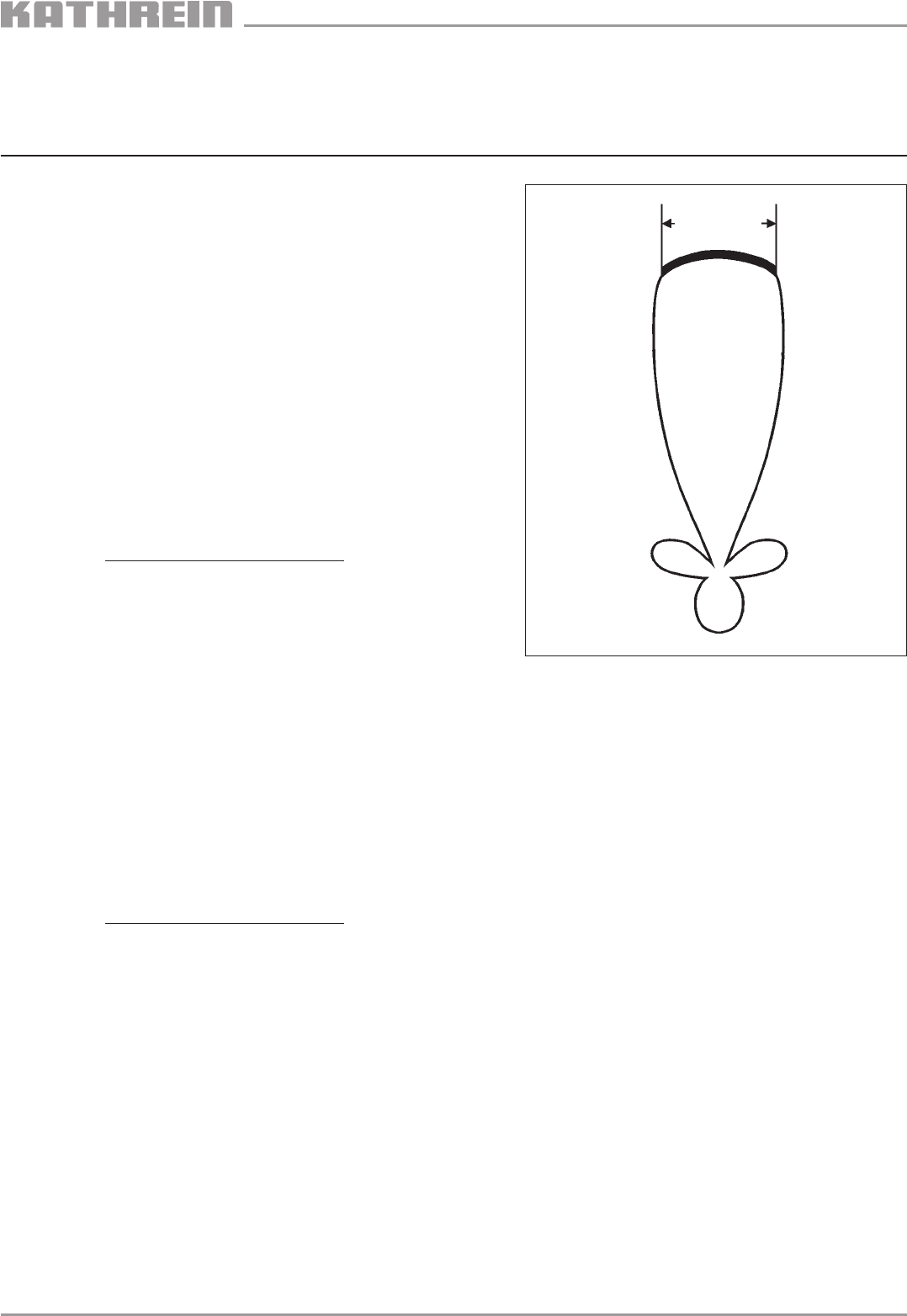
Abb./Fig./Illustr. 5
Da die Antennenkeule im Bereich des Maximums nur leicht ge-
krümmt ist, ist bei Ausrichtung in diesem Bereich zwar eine gute
Bildqualität zu erwarten, es kann aber sein, dass die Antenne links
oder rechts gerade noch auf diesen „guten Empfangsbereich“ ge-
richtet ist.
Schon beim ersten Schwanken des Antennenstandrohres im Wind
wird die gute Bildqualität über die steilen Keulenflanken „abstürzen“.
Um das zu vermeiden, sollte die Empfangsanlage auf die Mitte des
Pegelmaximums eingestellt werden.
Zur Einstellung mit einem Kathrein Satelliten-Messempfänger MSK…
gehen Sie wie folgt vor:
1. Die Mitte der Mastschelle markieren.
2. Antenne nach links drehen, bis Pegelabfall von z. B. 8 dB
(oder Spikes) auftritt.
Mastschellenmarkierung auf den Mast übertragen.
3. Antenne nach rechts drehen, bis Pegelabfall von z. B. 8 dB auftritt.
Mastschellenmarkierung auf den Mast übertragen.
4. Stellen Sie die Mastschellenmarkierung genau in die Mitte der
Mastmarkierungen. So erreichen Sie die bestmöglichste
Empfangssituation.
Für die Elevationsoptimierung ist sinngemäß zu verfahren.
Since the lobe representing maximum reception is only slightly bent, you
can expect good reception within the lobe. However, it may be that the
alignment of the antenna is bordering the left or right limits of the lobe,
which will mean that good reception will drop away as soon as the mast
starts swaying a little.
In order to avoid this, align the reception system as close as possible to
the middle of the level maximum.
For azimuth alignment with a Kathrein measuring instrument MSK…
proceed as follows:
1. Set a marker at the middle of the mast clamp.
2. Turn the antenna to the left until the level has dropped by about
8 dB or until you see „spikes“.
Transfer the marker on the mast clamp to the antenna mast.
3. Turn the antenna to the right until the level has dropped by about
8 dB or until you see „spikes“.
4. Place the marker on the mast clamp exactly in the middle of the
markers on the mast.
This will ensure maximum reception.
As to the elevation alignment, proceed correspondingly.
Etant donné que le lobe de l’antenne qui représente la plage maximum de
réception n’est courbé que légèrement, le positionnement de l’antenne
dedans cette plage assurera une bonne réception. Toutefois, il se peut
que le positionnement touche les frontières du lobe, ce que veut dire que
la bonne réception se termine dès que la mât d’antenne commence à
vaciller.
Afin d’empêcher cette possibilité, il est recommandé d’ajuster le système
le plus proche possible sur le milieu du niveau maximum.
Pour un positionnement azimut à l’aide d’un mesureur MSK…
Kathrein, procéder comme suit:
1. Faire un marquage au milieu du collier de serrage.
2. Tourner l’antenne vers la gauche jusqu’à ce que le niveau se soit abais-
sé d’environ 8 dB ou jusqu’au moment où des „clics“ apparaissent.
Transferer le marquage du collier de serrage vers le mât d’antenne.
3. Tourner l’antenne vers la droite jusqu’à ce que le niveau se soit abaissé
d’environ 8 dB ou jusqu’au moment où des „clics“ apparaissent.
Transmettre le marquage du collier de serrage vers le mât d’antenne.
4. Placez le marquage du collier de serrage exactement au milieu des
marquages sur le mât. Cela vous aidera à obtenir une bonne réception.
Pour le positionnement d’élévation, procéder conformément.
Pegelmaximum
Level maximum
Niveau maximum
936.2681/C/0906/5.6def
Typ / Type UAS 177
Bestell-Nr. / Order Nr. / Numéro de commande 268105
Geeignet für Parabolspiegel
Suitable for dish antennas CAS 06, 60, 075, 75, 75/R, 09, 90, 90/R, 120, 1801)
Pour des antennes paraboliques
Polarisation 2 x (1 x horizontal und 1 x vertikal), umschaltbar
Polarisation 2 x (1 x horizontal and 1 x vertical) switchable
Polarisation 2 x (1 x horizontale et 1 x verticale) commutable
Eingangsfrequenz Umschaltbar 10,70–11,70 (Schaltsignal: 0 kHz)
Input frequency umschaltbar 11,70–12,75 (Schaltsignal: 22 kHz)
Fréquence d’entrée GHz switchable 10,70 – 11,70 (switchsignal 0 kHz)
switchable 11,70 – 12,75 (switchsignal 22 kHz)
commutable 10,70 – 11,70 (signal de comm. 0 kHz)
commutable 11,70 – 12,75 (signal de comm. 22 kHz
Speisesystem-Rauschmaß / 25 °C
Feed system noise figure / 25°C dB 0,9
Facteur de bruit de la tête / 25°C
LNB-Rauschmaß / 25 °C
LNB noise figure / 25°C dB 0,8
Facteur de bruit du LNB / 25°C
Verstärkung / Gain / Gain dB > 50
Ausgangsfrequenz/Output frequency/Fréquency de sortie MHz 950-1950/1100-2150
Oszillatorfrequenz
Oscillator frequency GHz 9,750/10,6
Fréquence d’oscillator local (l. o.)
Phasenrauschen (LO: 10,60 GHz)
Phase noise (LO: 10,60 GHz) dB/K 1 kHz – 50, 10 kHz – 75, 100 kHz – 95
Bruit de phase (o.l. 10,60 GHz)
Systemgüte (G/T) (bei 11,3 GHz/12,5 GHz) dB/K CAS 06, 60 14,7/15,7 CAS 120 21,7/22,6
System figure of quality (G/T) (at 11,3 GHz/12,5 GHz) CAS 075, 75, 75/R 16,9/17,8
Facteur de qualité (G/T) (à 11,3 GHz/12,5 GHz) CAS 09, 90, 90/R 18,5/19,5
Polarisationsentkopplung
Polarisation decoupling dB > 23
Découplage de polarisation
Ausgang/Impedanz
Output /Impedance Ω1 x F-Connector/75
Sortie/Impédance
Versorgungsspannung LNB
Supply voltage LNB V + 11,5-14 vertikal
Tension d’alimentation LNB + 16-19 horizontal
Stromaufnahme LNB
Supply voltage LNB mA < 150
Tension d’alimentation LNB
Abmessungen / Dimensions / Dimensions mm 250 x 44 x 148
Gewicht ca. / Weight / Poids kg 1,25
Verpackungsmaße
Packing size / Dimensions emballage mm 270 x 70 x 165
Umschaltung oberer Frequenzbereich (digitaler Bereich)
Vom Receiver kann der Versorgungsspannung ein 22-kHz-Signal überlagert werden. Mit diesem Schaltsignal kann der LNB in
den oberen Frequenzbereich umgeschaltet werden, der Lokaloszillator mit f = 10,6 GHz ist dann aktiv.
Change-over to upper frequency range (digital range)
Superposition of the LNB supply voltage with a 22 kHz control signal will be accomplished from the receiver. With this signal, the
LNBs is switched to the upper frequency range. The local oscillator frequency is then f = 10.6 GHz.
Commutation de la fréquence supérieure (Gamme numérique)
La téléalimentation délivrée par le récepteur satellite peut être superposée par le signal de 22 kHz.
Ce signal permet de commuter le LNB vers la gamme de fréquence supérieure et l’oscillateur local travaille maintenant sur
f=10,6 GHz.
U01
112
K
1) Um Übersteuerungen des Speisesystems zu
vermeiden, CAS 180 nur in Randgebieten der
Satelliten-Ausleuchtzonen verwenden.
1) In order to avoid overmodulation of the feed system,
use the CAS 180 only in the rims of the satellite
footprints.
1) Pour éviler la surmodulation du système
d’alimentation, utiliser le CAS 180 seulement en
bords d’illumination satellite.
936.2681/C/0906/6.6def/SKS Technische Änderungen vorbehalten. Subjet to modifications. Nous nous réservons le droit de toutes modifications techniques.
KATHREIN-Werke KG · Anton-Kathrein-Straße 1–3 · Postfach 10 04 44 · D-83004 Rosenheim · Deutschland · Telefon (0 80 31) 18 40 · Telefax (0 80 31) 18 43 06
Polarisationsvoreinstellungen
in verschiedenen Ländern
für Compact-Speisesystem
Pre-setting the polarisation
for Compact Feed Systems
in different countries
Présélection de la
polarisation des têtes
compactes SHF pour
différents pays
Weitere Länder bzw. Städte in diesen Ländern finden Sie im Internet auf der Kathrein-Homepage unter www.kathrein.de/de/sat/index.htm
im Menüpunkt „Satelliten-Empfangsanlagen / Technische Infos / Azimut/Elevation und Polarisations-Voreinstellung“.
Find more countries or cities respectively on the Kathrein-homepage on the internet www.kathrein.de/de/sat/index.htm,
in the menu item ”satellite receiving systems / technical information / Azimut/Elevation and polarisation-presetting“
Trouvez d’autres pays ou villes sur notre page dans l’internet www.kathrein.de/de/sat/index.htm
dans le point de menu ”satellite receiving systems / technical information / Azimut/Elevation and polarisation-presetting“
