Kawasaki Kle500 Service Manual .....v...r...[ D
2014-12-11
: Kawasaki Kawasaki-Kle500-Service-Manual-120356 kawasaki-kle500-service-manual-120356 kawasaki pdf
Open the PDF directly: View PDF ![]() .
.
- tables
- LIST OF ABBREVIATIONS
- Units of Mass:
- Units of Volume:
- Units of Force:
- Units of Length:
- Units of Torque:
- Units of Pressure:
- Units of Speed:
- Units of Power:
- Periodic Replacement Parts
- Basic Torque for General Fasteners
- Throttle Grip Free Play
- Idle Speed
- Valve Clearance Measuring Position
- Valve Clearance Measuring Position
- Valve Clearance (when cold)
- Clutch Lever Free Play
- Air Pressure (when cold)
- Tread Depth
- Rim Runout (with tire installed)
- Chain Slack
- Drive Chain 20-link Length
- Recommended Disc Brake Fluid
- Pad Lining Thickness
- Brake Light Timing
- Spark Plug Gap
- Sidestand Switch Operation
- Water and Coolant Mixture Ratio (when shipping)
- Engine Oil
- Choke Cable Free Play
- Fuel Level
- Float Height
- Valve Closing Temperature (for reference)
- Radiator Cap Relief Pressure
- Thermostat Valve Opening Temperature
- Vacuum Switch Valve Closing Pressure (open → close)
- Camshaft Journal, Camshaft Cap Clearance
- Cylinder Compression (Usable Range)
- Cylinder Head Warp
- Valve Seating Surface Outside Diameter
- Valve Seating Surface Width
- Valve/Valve Guide Clearance (Wobble Method)
- Special Tools -
- Piston Ring/Groove Clearance
- Piston Ring End Gap
- Cylinder Inside Diameter
- Piston Diameter
- Friction Plate Thickness
- Friction and Steel Plate Warp
- Clutch Spring Free Length
- Oil Pressure
- Torque Value for 8 mm Bolts
- Connecting Rod Bend
- Connecting Rod Twist
- Connecting Rod Big End Side Clearance
- Connecting Rod Big End Bearing Insert/Crankpin Clearance
- Crankpin Diameter
- Crankpin Diameter Marks
- Connecting Rod Big End Bore Diameter Marks
- Connecting Rod Big End Bearing Insert Selection
- Crankshaft Runout
- Crankshaft Main Bearing Insert/Journal Clearance
- Crankshaft Main Journal Diameter
- Crankshaft Main Journal Diameter Marks
- Crankcase Main Bearing Bore Diameter Marks
- Crankshaft Main Bearing Insert Selection
- Crankshaft Side Clearance
- Balancer Shaft Bearing Insert/Journal Clearance
- Balancer Shaft Journal Diameter
- Balancer Shaft Diameter Marks
- Crankcase Bearing Bore Diameter Marks
- Balancer Shaft Bearing Insert Selection
- Axle Runout/100 mm (3.94 in.)
- Balance Weight
- Recommended Tool
- Link Pin Outside Diameter
- Link Plates Outside Width
- Rear Sprocket Warp
- Pedal Position
- Disc Thickness
- Disc Runout
- Front Fork Oil Level (Fully compressed without fork spring)
- Spring Free Length
- Spring Preload Adjustment
- Kawasaki-recommended chargers:
- Battery Terminal Voltage
- Terminal Voltage: 11.5 ∼ less than 12.8 V
- Terminal Voltage: less than 11.5 V
- Voltage
- Table 2 Stator Coil Resistance
- Regulator/Rectifier Output Voltage
- Rectifier Circuit Inspection
- Crankshaft Sensor Resistance
- Ignition Coil Arcing Distance
- Ignition Coil Winding Resistance
- Ignition Timing
- Connect
- Ignition Coil Primary Peak Voltage
- Connect
- Crankshaft Sensor Peak Voltage
- Starter Motor Brush Length
- Commutator Diameter
- Testing Relay
- Testing Turn Signal Relay
- Wire Connectors
- Radiator Fan Switch Resistance
- Water Temperature Switch Connections
- Fuse Circuit Inspection
- Relay Circuit Inspection (with the battery disconnected)
- Relay Circuit Inspection (with the battery connected)
- Diode Circuit Inspection
- toc
- Read OWNER'S MANUAL before operating.
- Foreword
- General Information
- Before starting to perform an inspection service or carry out a
- Battery Ground
- Edges of Parts
- Solvent
- Cleaning vehicle before disassembly
- Arrangement and Cleaning of Removed Parts
- Storage of Removed Parts
- Inspection
- Replacement Parts
- Assembly Order
- Tightening Sequence
- Tightening Torque
- Force
- Gasket, O-ring
- Liquid Gasket, Locking Agent
- Press
- Ball Bearing and Needle Bearing
- Oil Seal, Grease Seal
- Circlips, Cotter Pins
- Lubrication
- Direction of Engine Rotation
- Electrical Wires
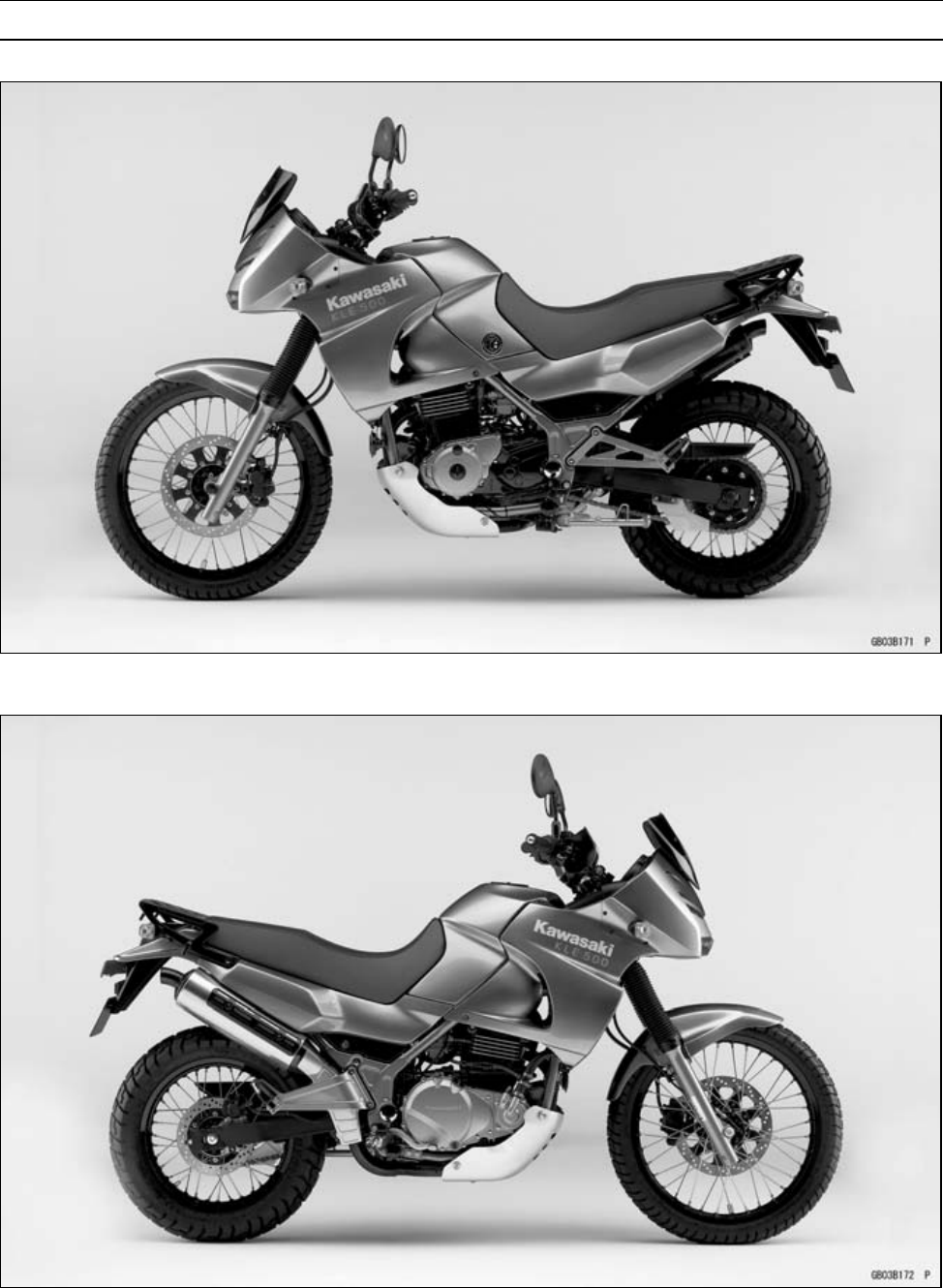
- KLE500-B1 Left Side View
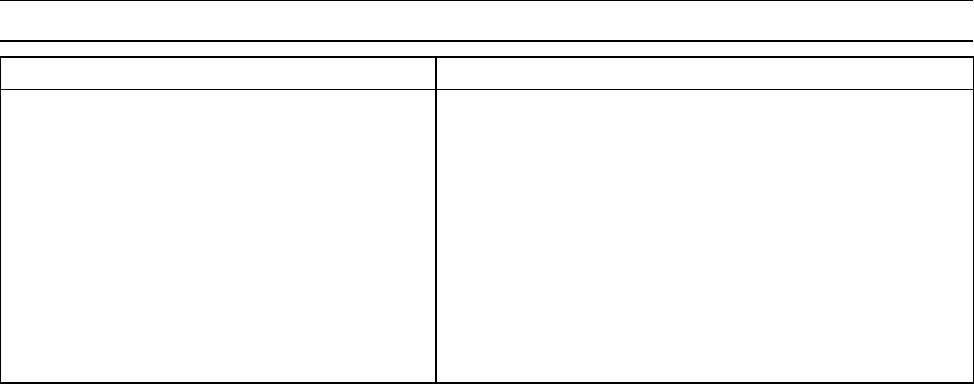
- KLE500-B1 Right Side View
- Prefixes for Units:
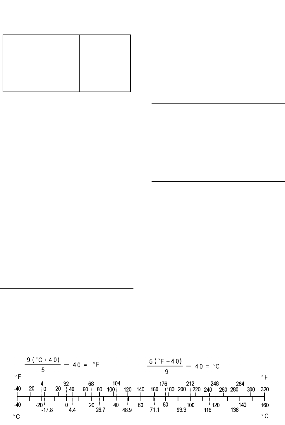
- Units of Temperature:
- Before starting to perform an inspection service or carry out a
- Periodic Maintenance
- The scheduled maintenance must be done in accordance with this c
- Tighten all bolts and nuts to the proper torque using an accurat
- Steering Stem Nut Wrench:
- Fuel System
- Throttle Cable Inspection
- Idle Speed Inspection
- Carburetor Synchronization Inspection
- Coolant Filter Cleaning
- Fuel Hoses and Connections Check
- Air Cleaner Element Cleaning and Inspection
- Cooling System
- Engine Top End
- Clutch
- Wheels/Tires
- Final Drive
- Brakes
- Suspension
- Steering
- Electrical System
- Others
- Replacement Parts
- Fuel System
- Cooling System
- Engine Top End
- Clutch
- Engine Lubrication System
- Engine Removal/Installation
- Crankshaft/Transmission
- Bearing Puller:
- Crankcase Splitting
- Clutch Housing/Primary Chain Removal
- Crankshaft Removal
- Crankshaft Installation
- Connecting Rod Removal
- Connecting Rod Installation
- Crankshaft/Connecting Rod Cleaning
- Connecting Rod Bend/Twist
- Connecting Rod Big End Side Clearance
- Connecting Rod Big End Bearing Insert/Crankpin Clearance
- Crankshaft Runout
- Crankshaft Main Bearing Insert/Journal Clearance
- Crankshaft Side Clearance
- Balancer Removal
- External Shift Mechanism Removal
- External Shift Mechanism Installation
- External Shift Mechanism Inspection
- Transmission Shaft Removal
- Transmission Shaft Installation
- Transmission Shaft Disassembly
- Drive Shaft Assembly
- Output Shaft Assembly
- Shift Drum and Fork Removal
- Shift Drum and Fork Installation
- Shift Drum Disassembly
- Shift Drum Assembly
- Ball and Needle Bearing Wear
- Shift Pedal Installation
- Wheels/Tires
- Final Drive
- Inside Circlip Pliers:
- Drive Chain Slack Inspection
- Engine Sprocket Removal
- Brakes
- Suspension
- Steering
- Frame
- Electrical System
- Outside Circlip Pliers:
- There are a number of important precautions that are musts when
- Wiring Inspection
- Battery Removal/Installation
- Alternator Rotor/Starter Clutch Removal
- Special Tool -
- Special Tool -
- Starter Clutch Sprocket Removal
- Starter Clutch Sprocket Installation
- Alternator Rotor/Starter Clutch Installation
- Alternator Stator Removal
- Alternator Stator Installation
- Alternator Inspection
- Regulator/Rectifier Removal
- Regulator/Rectifier Output Voltage Inspection
- Regulator/Rectifier Inspection
- Charging System Circuit
- Ignition System Circuit
- Electric Starter Circuit
- Headlight Circuit
- Headlight Beam Horizontal Adjustment
- Headlight Beam Vertical Adjustment
- Headlight Bulb Replacement
- Headlight Unit/Housing Removal
- Headlight Unit/Housing Installation
- City Light Bulb Replacement
- Tail/Brake Light Bulb Replacement
- Tail/Brake Light Lens Removal/Installation
- Turn Signal Light Bulb Replacement
- Turn Signal Relay Inspection
- Turn Signal Light Circuit
- Fan System Circuit Inspection
- Meter Unit Removal
- Brake Light Switch Inspection
- The junction box [A] has fuses [B], relays, and diodes. The rela
- 30 A Main Fuse Removal
- Appendix
- NOTE
- Engine Doesn't Start, Starting Difficulty:
- Poor Running at Low Speed:
- Poor Running or No Power at High Speed:
- Overheating:
- Over Cooling:
- Clutch Operation Faulty:
- Gear Shifting Faulty:
- Abnormal Engine Noise:
- Abnormal Drive Train Noise:
- Abnormal Frame Noise:
- Oil Pressure Warning Light Goes On:
- Exhaust Smokes Excessively:
- Handling and/or Stability Unsatisfactory:
- Brake Doesn't Hold:
- Battery Trouble:
- NOTE
- Read OWNER'S MANUAL before operating.
This quick reference guide will assist
you in locating a desired topic or pro-
cedure.
•Bend the pages back to match the
black tab of the desired chapter num-
ber with the black tab on the edge at
each table of contents page.
•Refer to the sectional table of contents
for the exact pages to locate the spe-
cific topic required.
Quick Reference Guide
General Information 1 j
Periodic Maintenance 2 j
Fuel System 3 j
Cooling System 4 j
Engine Top End 5 j
Clutch 6 j
Engine Lubrication System 7 j
Engine Removal/Installation 8 j
Crankshaft/Transmission 9 j
Wheels/Tires 10 j
Final Drive 11 j
Brakes 12 j
Suspension 13 j
Steering 14 j
Frame 15 j
Electrical System 16 j
Appendix 17 j

KLE500
Motorcycle
Service Manual
All rights reserved. No parts of this publication may be reproduced, stored in a retrieval system, or
transmitted in any form or by any means, electronic mechanical photocopying, recording or otherwise,
without the prior written permission of Quality Division/Consumer Products & Machinery Company/Kawasaki
Heavy Industries, Ltd., Japan.
No liability can be accepted for any inaccuracies or omissions in this publication, although every possible
care has been taken to make it as complete and accurate as possible.
The right is reserved to make changes at any time without prior notice and without incurring an obligation
to make such changes to products manufactured previously. See your Motorcycle dealer for the latest
information on product improvements incorporated after this publication.
All information contained in this publication is based on the latest product information available at the time
of publication. Illustrations and photographs in this publication are intended for reference use only and may
not depict actual model component parts.
© 2004 Kawasaki Heavy Industries, Ltd. First Edition (1): Dec. 10, 2004 (K)

LIST OF ABBREVIATIONS
Aampere(s) lb pound(s)
ABDC after bottom dead center mmeter(s)
AC alternating current min minute(s)
ATDC after top dead center Nnewton(s)
BBDC before bottom dead center Pa pascal(s)
BDC bottom dead center PS horsepower
BTDC before top dead center psi pound(s) per square inch
°C degree(s) Celsius rrevolution
DC direct current rpm revolution(s) per minute
Ffarad(s) TDC top dead center
°F degree(s) Fahrenheit TIR total indicator reading
ft foot, feet Vvolt(s)
ggram(s) Wwatt(s)
hhour(s) Ωohm(s)
Lliter(s)
Read OWNER’S MANUAL before operating.
Foreword
This manual is designed primarily for use by
trained mechanics in a properly equipped shop.
However, it contains enough detail and basic in-
formation to make it useful to the owner who de-
sires to perform his own basic maintenance and
repair work. A basic knowledge of mechanics,
the proper use of tools, and workshop proce-
dures must be understood in order to carry out
maintenance and repair satisfactorily. When-
ever the owner has insufficient experience or
doubts his ability to do the work, all adjust-
ments, maintenance, and repair should be car-
ried out only by qualified mechanics.
In order to perform the work efficiently and
to avoid costly mistakes, read the text, thor-
oughly familiarize yourself with the procedures
before starting work, and then do the work care-
fully in a clean area. Whenever special tools or
equipment are specified, do not use makeshift
tools or equipment. Precision measurements
can only be made if the proper instruments are
used, and the use of substitute tools may ad-
versely affect safe operation.
For the duration of the warranty period,
we recommend that all repairs and scheduled
maintenance be performed in accordance with
this service manual. Any owner maintenance or
repair procedure not performed in accordance
with this manual may void the warranty.
To get the longest life out of your vehicle:
•Follow the Periodic Maintenance Chart in the
Service Manual.
•Be alert for problems and non-scheduled
maintenance.
•Use proper tools and genuine Kawasaki Mo-
torcycle parts. Special tools, gauges, and
testers that are necessary when servicing
Kawasaki motorcycles are introduced by the
Special Tool Catalog or Manual. Genuine
parts provided as spare parts are listed in the
Parts Catalog.
•Follow the procedures in this manual care-
fully. Don’t take shortcuts.
•Remember to keep complete records of main-
tenance and repair with dates and any new
parts installed.
How to Use This Manual
In this manual, the product is divided into its
major systems and these systems make up the
manual’s chapters.
The Quick Reference Guide shows you all
of the product’s system and assists in locating
their chapters. Each chapter in turn has its own
comprehensive Table of Contents.
For example, if you want ignition coil informa-
tion, use the Quick Reference Guide to locate
the Electrical System chapter. Then, use the
Table of Contents on the first page of the chap-
ter to find the ignition coil section.
Whenever you see these WARNING and
CAUTION symbols, heed their instructions!
Always follow safe operating and maintenance
practices.
WARNING
This warning symbol identifies special
instructions or procedures which, if not
correctly followed, could result in per-
sonal injury, or loss of life.
CAUTION
This caution symbol identifies special
instructions or procedures which, if not
strictly observed, could result in dam-
age to or destruction of equipment.
This manual contains four more symbols (in
addition to WARNING and CAUTION) which will
help you distinguish different types of informa-
tion.
NOTE
○This note symbol indicates points of par-
ticular interest for more efficient and con-
venient operation.
•Indicates a procedural step or work to be
done.
○Indicates a procedural sub-step or how to do
the work of the procedural step it follows. It
also precedes the text of a NOTE.
Indicates a conditional step or what action to
take based on the results of the test or inspec-
tion in the procedural step or sub-step it fol-
lows.
In most chapters an exploded view illustration
of the system components follows the Table of
Contents. In these illustrations you will find the
instructions indicating which parts require spec-
ified tightening torque, oil, grease or a locking
agent during assembly.
GENERAL INFORMATION 1-1
1
General Information
Table of Contents
Before Servicing ..................................................................................................................... 1-2
Model Identification................................................................................................................. 1-7
General Specifications............................................................................................................ 1-8
Unit Conversion Table ............................................................................................................ 1-11
1-2 GENERAL INFORMATION
Before Servicing
Before starting to perform an inspection service or carry out a disassembly and reassembly opera-
tion on a motorcycle, read the precautions given below. To facilitate actual operations, notes, illustra-
tions, photographs, cautions, and detailed descriptions have been included in each chapter wherever
necessary. This section explains the items that require particular attention during the removal and
reinstallation or disassembly and reassembly of general parts.
Especially note the following:
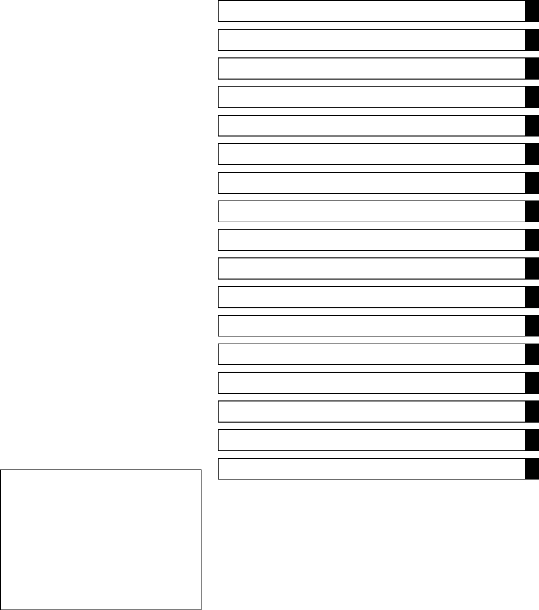
Battery Ground
Before completing any service on the motorcycle, discon-
nect the battery wires from the battery to prevent the engine
from accidentally turning over. Disconnect the negative wire
(–) first and then the positive (+). When completed with the
service, first connect the positive (+) wire to the positive (+)
terminal of the battery then the negative (–) wire to the neg-
ative terminal.
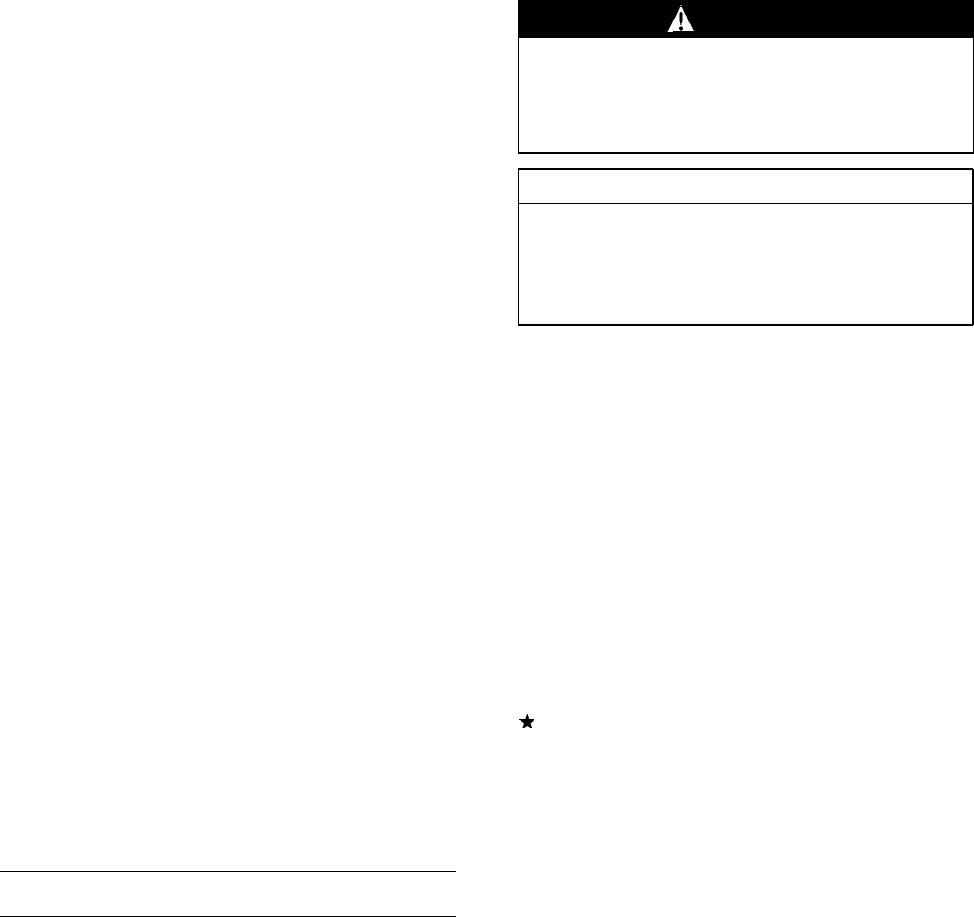
Edges of Parts
Lift large or heavy parts wearing gloves to prevent injury
from possible sharp edges on the parts.
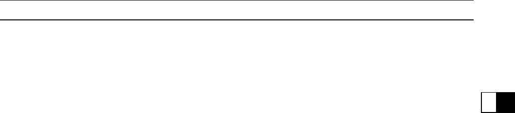
Solvent
Use a high flush point solvent when cleaning parts. High
flush point solvent should be used according to directions
of the solvent manufacturer.
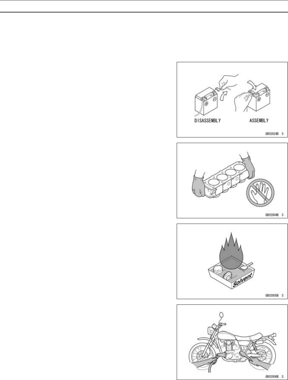
Cleaning vehicle before disassembly
Clean the vehicle thoroughly before disassembly. Dirt or
other foreign materials entering into sealed areas during ve-
hicle disassembly can cause excessive wear and decrease
performance of the vehicle.
GENERAL INFORMATION 1-3
Before Servicing
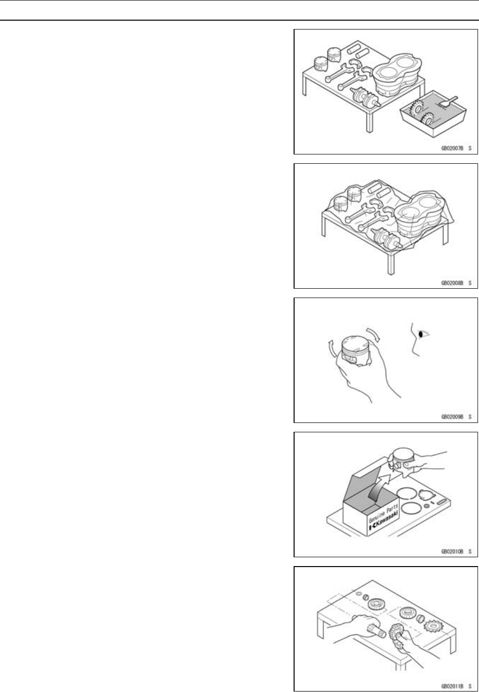
Arrangement and Cleaning of Removed Parts
Disassembled parts are easy to confuse. Arrange the
parts according to the order the parts were disassembled
and clean the parts in order prior to assembly.
Storage of Removed Parts
After all the parts including subassembly parts have been
cleaned, store the parts in a clean area. Put a clean cloth
or plastic sheet over the parts to protect from any foreign
materials that may collect before re-assembly.
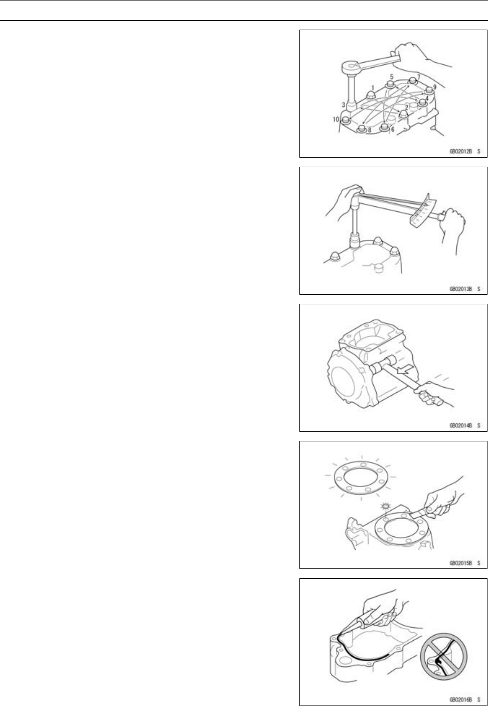
Inspection
Reuse of worn or damaged parts may lead to serious ac-
cident. Visually inspect removed parts for corrosion, discol-
oration, or other damage. Refer to the appropriate sections
of this manual for service limits on individual parts. Replace
the parts if any damage has been found or if the part is be-
yond its service limit.
Replacement Parts
Replacement Parts must be KAWASAKI genuine or
recommended by KAWASAKI. Gaskets, O-rings, Oil seals,
Grease seals, circlips or cotter pins must be replaced with
new ones whenever disassembled.
Assembly Order
In most cases assembly order is the reverse of disassem-
bly, however, if assembly order is provided in this Service
Manual, follow the procedures given.
1-4 GENERAL INFORMATION
Before Servicing
Tightening Sequence
Generally, when installing a part with several bolts, nuts,
or screws, start them all in their holes and tighten them to
a snug fit. Then tighten them according to the specified se-
quence to prevent case warpage or deformation which can
lead to malfunction. Conversely when loosening the bolts,
nuts, or screws, first loosen all of them by about a quar-
ter turn and them remove them. If the specified tightening
sequence is not indicated, tighten the fasteners alternating
diagonally.
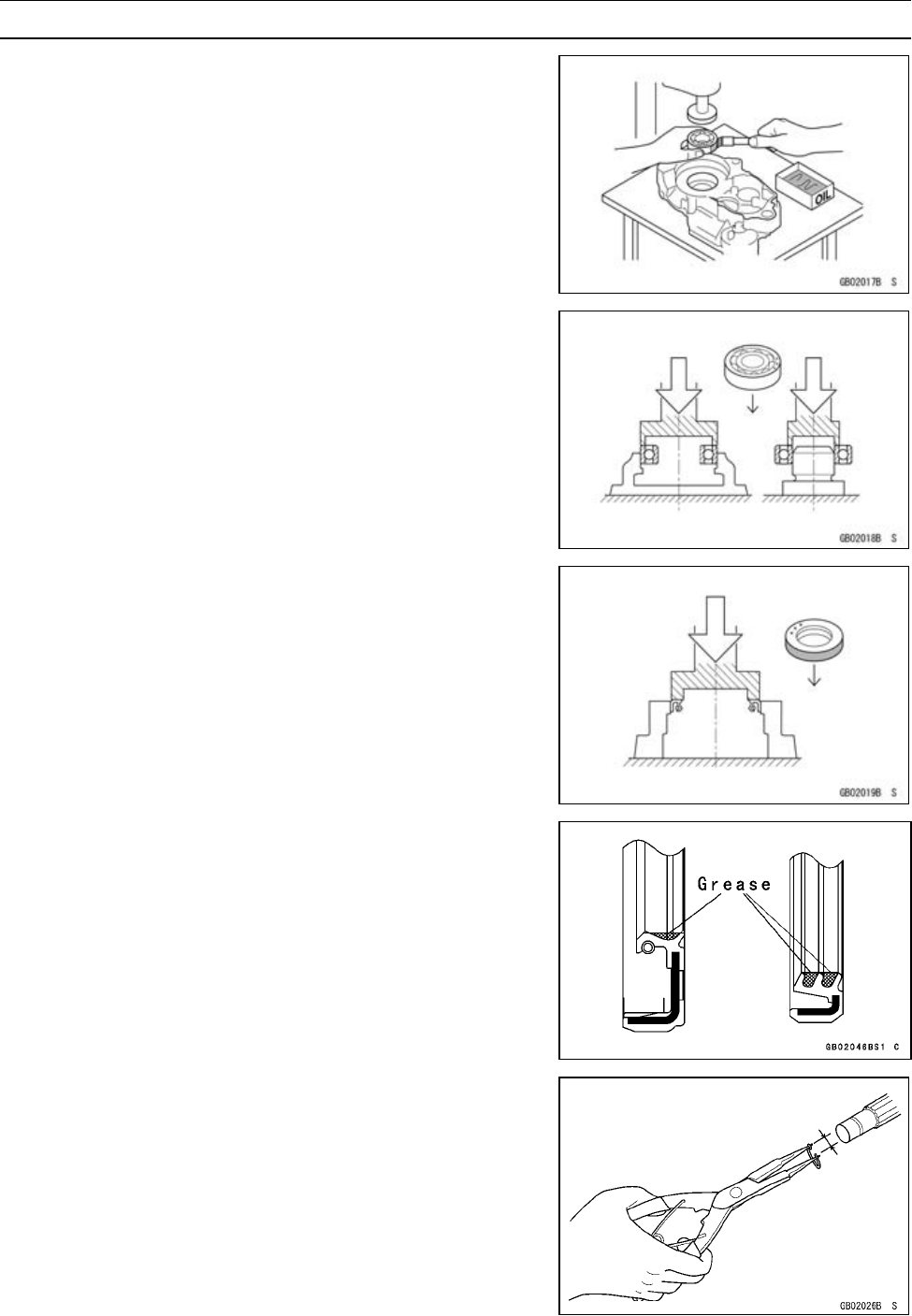
Tightening Torque
Incorrect torque applied to a bolt, nut, or screw may
lead to serious damage. Tighten fasteners to the specified
torque using a good quality torque wrench.
Force
Use common sense during disassembly and assembly,
excessive force can cause expensive or hard to repair dam-
age. When necessary, remove screws that have a non
-permanent locking agent applied using an impact driver.
Use a plastic-faced mallet whenever tapping is necessary.
Gasket, O-ring
Hardening, shrinkage, or damage of both gaskets
and O-rings after disassembly can reduce sealing per-
formance. Remove old gaskets and clean the sealing
surfaces thoroughly so that no gasket material or other
material remains. Install new gaskets and replace used
O-rings when re-assembling.
Liquid Gasket, Locking Agent
For applications that require Liquid Gasket or a Locking
agent, clean the surfaces so that no oil residue remains be-
fore applying liquid gasket or locking agent. Do not apply
them excessively. Excessive application can clog oil pas-
sages and cause serious damage.
GENERAL INFORMATION 1-5
Before Servicing
Press
For items such as bearings or oil seals that must be
pressed into place, apply small amount of oil to the con-
tact area. Be sure to maintain proper alignment and use
smooth movements when installing.
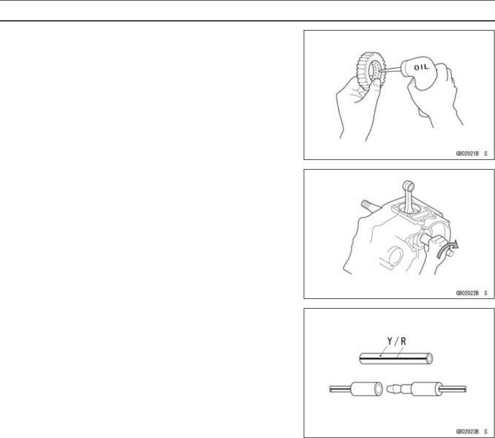
Ball Bearing and Needle Bearing
Do not remove pressed ball or needle unless removal is
absolutely necessary. Replace with new ones whenever
removed. Press bearings with the manufacturer and size
marks facing out. Press the bearing into place by putting
pressure on the correct bearing race as shown.
Pressing the incorrect race can cause pressure between
the inner and outer race and result in bearing damage.
Oil Seal, Grease Seal
Do not remove pressed oil or grease seals unless removal
is necessary. Replace with new ones whenever removed.
Press new oil seals with manufacture and size marks facing
out. Make sure the seal is aligned properly when installing.
Apply specified grease to lip of seal before installing the
seal.
Circlips, Cotter Pins
Replace circlips or cotter pins that were removed with new
ones. Take care not to open the clip excessively when in-
stalling to prevent deformation.
1-6 GENERAL INFORMATION
Before Servicing
Lubrication
It is important to lubricate rotating or sliding parts during
assembly to minimize wear during initial operation. Lubri-
cation points are called out throughout this manual, apply
the specific oil or grease as specified.
Direction of Engine Rotation
When rotating the crankshaft by hand, the free play
amount of rotating direction will affect the adjustment. Ro-
tate the crankshaft to positive direction (clockwise viewed
from output side).
Electrical Wires
A two-color wire is identified first by the primary color and
then the stripe color. Unless instructed otherwise, electrical
wires must be connected to those of the same color.
GENERAL INFORMATION 1-7
Model Identification
KLE500-B1 Left Side View
KLE500-B1 Right Side View

1-8 GENERAL INFORMATION
General Specifications
Items KLE500-B1
Dimensions
Overall Length 2 215 mm (87.2 in.)
Overall Width 880 mm (34.6 in.)
Overall Height 1 270 mm (50.0 in.)
Wheelbase 1 500 mm (59.0 in.)
Road Clearance 180 mm (7.09 in.)
Seat Height 850 mm (33.5 in.)
Dry Weight 181 kg (399 lb.)
Curb Weight:
Front 95 kg (209 lb.)
Rear 105 kg (232 lb.)
Fuel tank Capacity 15 L (4.0 US gal.)
Performance
Minimum Turning Radius 2.4 m (7.9 ft.)
Engine
Type 4-stroke, DOHC, 2-cylinder
Cooling System Liquid-cooled
Bore and Stroke 74.0 × 58.0 mm (2.91 × 2.28 in.)
Displacement 498 mL (30.39 cu in.)
Compression Ratio 9.8:1
Maximum Horsepower 33 kW (44.9 PS) @8 300 r/min (rpm)
Maximum Torque 41 N·m (4.2 kgf·m, 30 ft·lb) @7 500 r/min (rpm)
Carburetion System Carburetors, Keihin CVK34 × 2
Starting System Electric starter
Ignition System Battery and coil (transistorized)
Timing Advance Electronically Advanced (digital)
Ignition Timing From 10° BTDC @1 300 r/min (rpm) to 35° BTDC
@5 000 r/min (rpm)
Spark Plugs NGK DR9EA or ND X27ESR-U
Cylinder Numbering Method Left to right, 1-2
Firing Order 1-2
Valve Timing:
Inlet
Open 27° BTDC
Close 47° ABDC
Duration 254°
Exhaust
Open 52° BBDC
Close 22° ATDC
Duration 254°
Lubrication System Forced lubrication

GENERAL INFORMATION 1-9
General Specifications
Items KLE500-B1
Engine Oil:
Grade API SE, SF, SG or
API SH or SJ with JASO MA
Viscosity SAE10W-40
Capacity 3.4 L (3.6 US qt)
Drive Train
Primary Reduction System:
Type Chain
Reduction Ratio 2.652 (61/23)
Clutch Type Wet multi disc
Transmission:
Type 6-speed constant mesh, return shift
Gear Ratios:
1st 2.571 (36/14)
2nd 1.722 (31/18)
3rd 1.333 (28/21)
4th 1.125 (27/24)
5th 0.961 (25/26)
6th 0.851 (23/27)
Final Drive System:
Type Chain drive
Reduction Ratio 2.588 (44/17)
Overall Drive Ratio 5.847 @Top gear
Frame
Type Tubular, double cradle
Caster (rake angle) 27°
Trail 105 mm (4.13 in.)
Front Tire:
Type Tubeless
Size 90/90-21 M/C 54S
Rear Tire:
Type Tubeless
Size 130/80-17 M/C 65S
Front Suspension:
Type Telescopic fork
Wheel Travel 220 mm (8.66 in.)
Rear Suspension:
Type Swingarm
Wheel Travel 200 mm (7.87 in.)
Brake Type:
Front Single disc
Rear Single disc
1-10 GENERAL INFORMATION
General Specifications
Items KLE500-B1
Electrical Equipment
Battery 12 V 10 Ah
Headlight:
Type Semi-sealed beam
Bulb 12 V 55/55 W (quartz-halogen)
Tail/brake Light 12 V 5/21 W
Alternator:
Type Three-phase AC
Rated output 17 A × 14 V @6 000 r/min (rpm)
Specifications subject to change without notice, and may not apply to every country.
GENERAL INFORMATION 1-11
Unit Conversion Table
Prefixes for Units:
Prefix Symbol Power
mega M×1000000
kilo k× 1 000
centi c×0.01
milli m× 0.001
micro µ× 0.000001
Units of Mass:
kg ×2.205=lb
g × 0.03527 = oz
Units of Volume:
L × 0.2642 = gal (US)
L × 0.2200 = gal (imp)
L × 1.057 = qt (US)
L × 0.8799 = qt (imp)
L × 2.113 = pint (US)
L × 1.816 = pint (imp)
mL × 0.03381 = oz (US)
mL × 0.02816 = oz (imp)
mL × 0.06102 = cu in
Units of Force:
N × 0.1020 = kg
N × 0.2248 = lb
kg ×9.807=N
kg ×2.205=lb
Units of Length:
km × 0.6214 = mile
m × 3.281 = ft
mm × 0.03937 = in
Units of Torque:
N·m × 0.1020 = kgf·m
N·m × 0.7376 = ft·lb
N·m × 8.851 = in·lb
kgf·m × 9.807 = N·m
kgf·m ×7.233=ft·lb
kgf·m × 86.80 = in·lb
Units of Pressure:
kPa × 0.01020 = kgf/cm²
kPa × 0.1450 = psi
kPa × 0.7501 = cm Hg
kgf/cm² × 98.07 = kPa
kgf/cm² × 14.22 = psi
cm Hg × 1.333 = kPa
Units of Speed:
km/h × 0.6214 = mph
Units of Power:
kW × 1.360 = PS
kW × 1.341 = HP
PS × 0.7355 = kW
PS × 0.9863 = HP
Units of Temperature:

PERIODIC MAINTENANCE 2-1
2
Periodic Maintenance
Table of Contents
Periodic Maintenance Chart ................................................................................................... 2-3
Torque and Locking Agent...................................................................................................... 2-6
Specifications ......................................................................................................................... 2-11
Special Tools .......................................................................................................................... 2-13
Maintenance Procedure ......................................................................................................... 2-14
Fuel System......................................................................................................................... 2-14
Throttle Cable Inspection.................................................................................................. 2-14
Idle Speed Inspection ....................................................................................................... 2-15
Carburetor Synchronization Inspection............................................................................. 2-16
Coolant Filter Cleaning ..................................................................................................... 2-17
Fuel Hoses and Connections Check................................................................................. 2-17
Air Cleaner Element Cleaning and Inspection .................................................................. 2-17
Cooling System.................................................................................................................... 2-18
Coolant Level Inspection................................................................................................... 2-18
Radiator Hoses and Connections Inspection.................................................................... 2-19
Engine Top End ................................................................................................................... 2-19
Air Suction Valve Inspection ............................................................................................. 2-19
Valve Clearance Inspection .............................................................................................. 2-19
Clutch................................................................................................................................... 2-21
Clutch Operation Inspection.............................................................................................. 2-21
Wheels/Tires........................................................................................................................ 2-22
Air Pressure Inspection/Adjustment.................................................................................. 2-22
Tire Tread Wear Inspection............................................................................................... 2-22
Wheel/Tire Damage Inspection......................................................................................... 2-23
Wheel Bearing Damage Inspection .................................................................................. 2-24
Spoke Tightness and Rim Runout Inspection................................................................... 2-24
Final Drive............................................................................................................................ 2-25
Drive Chain Slack Inspection............................................................................................ 2-25
Drive Chain Wear Inspection ............................................................................................ 2-26
Drive Chain Lubrication..................................................................................................... 2-27
Brakes.................................................................................................................................. 2-27
Brake Fluid Leak (Brake Hose and Pipe) Inspection ........................................................ 2-27
Brake Hose Damage and Installation Condition Inspection.............................................. 2-28
Brake Operation Inspection .............................................................................................. 2-28
Brake Fluid Level Inspection............................................................................................. 2-28
Brake Pad Wear Inspection .............................................................................................. 2-29
Brake Light Switch Operation Inspection .......................................................................... 2-30
Suspension.......................................................................................................................... 2-30
Front Forks/Rear Shock Absorber Operation Inspection .................................................. 2-30
Front Fork Oil Leak Inspection.......................................................................................... 2-31
Rear Shock Absorber Oil Leak Inspection ........................................................................ 2-31
Rocker Arm Operation Inspection..................................................................................... 2-31
Rocker Arm Bearings and Sleeves Lubrication ................................................................ 2-31
Tie-rod Operation Inspection ............................................................................................ 2-32
Swingarm Needle Bearing Lubrication.............................................................................. 2-32
Steering ............................................................................................................................... 2-32

2-2 PERIODIC MAINTENANCE
Steering Play Inspection ................................................................................................... 2-32
Steering Stem Bearing Lubrication ................................................................................... 2-33
Electrical System ................................................................................................................. 2-34
Spark Plug Gap Inspection ............................................................................................... 2-34
Lights and Switches Operation Inspection........................................................................ 2-34
Headlight Aiming Inspection ............................................................................................. 2-36
Side Stand Switch Operation Inspection........................................................................... 2-37
Engine Stop Switch Operation Inspection......................................................................... 2-38
Others.................................................................................................................................. 2-38
Chassis Parts Lubrication ................................................................................................. 2-38
Bolts, Nuts and Fastener Tightness Inspection ................................................................ 2-39
Replacement Parts .............................................................................................................. 2-40
Fuel Hose Replacement ................................................................................................... 2-40
Air Cleaner Element Replacement.................................................................................... 2-41
Coolant Change................................................................................................................ 2-41
Radiator Hoses and O-ring Replacement ......................................................................... 2-44
Engine Oil Change............................................................................................................ 2-44
Oil Filter Replacement ...................................................................................................... 2-45
Brake Hose Replacement ................................................................................................. 2-45
Brake Fluid Change .......................................................................................................... 2-46
Bleeding the Brake Line.................................................................................................... 2-47
Caliper Rubber Parts Replacement .................................................................................. 2-48
Master Cylinder Rubber Parts Replacement .................................................................... 2-48
Spark Plug Replacement .................................................................................................. 2-49
PERIODIC MAINTENANCE 2-3
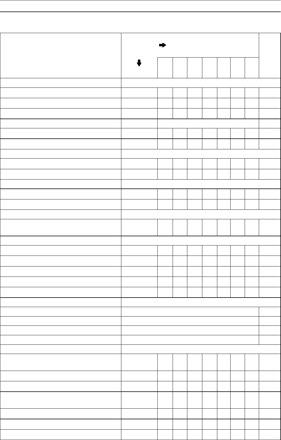
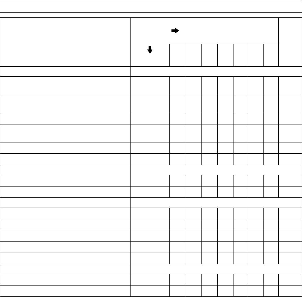
Periodic Maintenance Chart
The scheduled maintenance must be done in accordance with this chart to keep the motorcycle in
good running condition.The initial maintenance is vitally important and must not be neglected.
FREQUENCY Whichever
comes first
* ODOMETER READING
× 1000 km
(× 1000 mile)
1 6 12 18 24 30 36
OPERATION Every (0.6) (4) (7.5) (12) (15) (20) (24)
See
Page
Fuel System
Throttle cable-inspect year • • • • 2-14
Idle speed-inspect • • • • 2-15
Carburetor synchronization-inspect • • • 2-16
Coolant filter-clean year 2-17
Air cleaner element-clean # • • • 2-17
Fuel hoses and connections-inspect year • • • • 2-17
Cooling System
Coolant level-inspect • • • • 2-18
Radiator hose and connection-inspect year • • • • 2-19
Engine Top End
Air suction valve-inspect • • • 2-19
Valve clearance-inspect •2-19
Clutch
Clutch operation (play, disengagement,
engagement)-inspect • • • • 2-21
Wheels and Tires
Tire air pressure-inspect • • • • • • 2-22
Tire tread wear-inspect • • • 2-22
Wheel/tire damage-inspect • • • 2-23
Wheel bearing damage-inspect year • • • 2-24
Spoke tightness and rim runout-inspect • • • • • • • 2-24
Final Drive
Drive chain slack-inspect # Every 1 000 km (600 mile) 2-25
Drive chain wear-inspect # Every 6 000 km (4 000 mile) 2-26
Drive chain lubrication condition-inspect # Every 600 km (400 mile) 2-27
Drive chain guide wear-inspect Every 12 000 km (7 500 mile) –
Brake System
Brake fluid leak (brake hose and
pipe)-inspect year • • • • • • • 2-27
Brake hose damage-inspect year • • • • • • • 2-28
Brake hose installation condition-inspect year • • • • • • • 2-28
Brake operation (effectiveness, play, no
drag)-inspect year • • • • • • • 2-28
Brake fluid level-inspect 6 months • • • • • • • 2-28
Brake pad wear-inspect # • • • • • • 2-29
Brake light switch operation-inspect • • • • • • • 2-30
2-4 PERIODIC MAINTENANCE
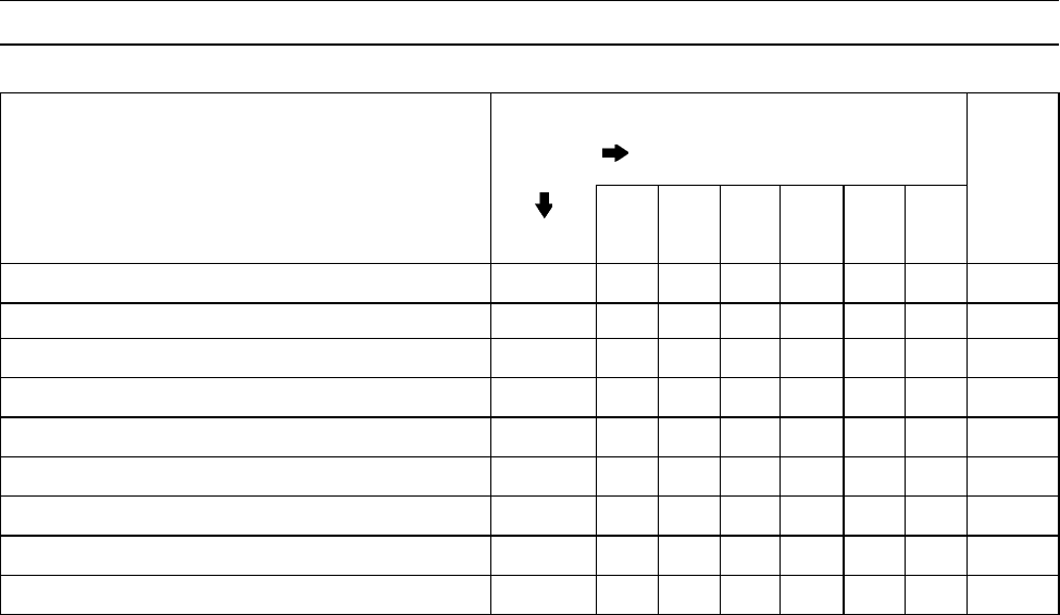
Periodic Maintenance Chart
FREQUENCY Whichever
comes first
* ODOMETER READING
× 1000 km
(× 1000 mile)
1 6 12 18 24 30 36
OPERATION Every (0.6) (4) (7.5) (12) (15) (20) (24)
See
Page
Suspensions
Front forks/rear shock absorber operation
(damping and smooth stroke)-inspect • • • 2-30
Front forks/rear shock absorber oil
leak-inspect year • • • 2-31
Rocker arm operation-inspect • • • 2-31
Rocker arm bearings and sleeves
-lubricate •2-31
Tie-rods operation-inspect • • • 2-32
Swingarm pivot-lubricate •2-32
Steering System
Steering play-inspect year • • • • 2-32
Steering stem bearings-lubricate 2 years •2-33
Electrical System
Spark plug condition-inspect • • • 2-34
Lights and switches operation-inspect year • • • 2-34
Headlight aiming-inspect year • • • 2-36
Side stand switch operation-inspect year • • • 2-37
Engine stop switch operation-inspect year • • • 2-38
Others
Chassis parts-lubricate year • • • 2-38
Bolts, nuts and fasteners tightness-inspect • • • • 2-39
#: Service more frequently when operating in severe conditions; dusty, wet, muddy, high speed or
frequent starting/stopping.
*: For higher odometer readings, repeat at the frequency interval established here.
PERIODIC MAINTENANCE 2-5
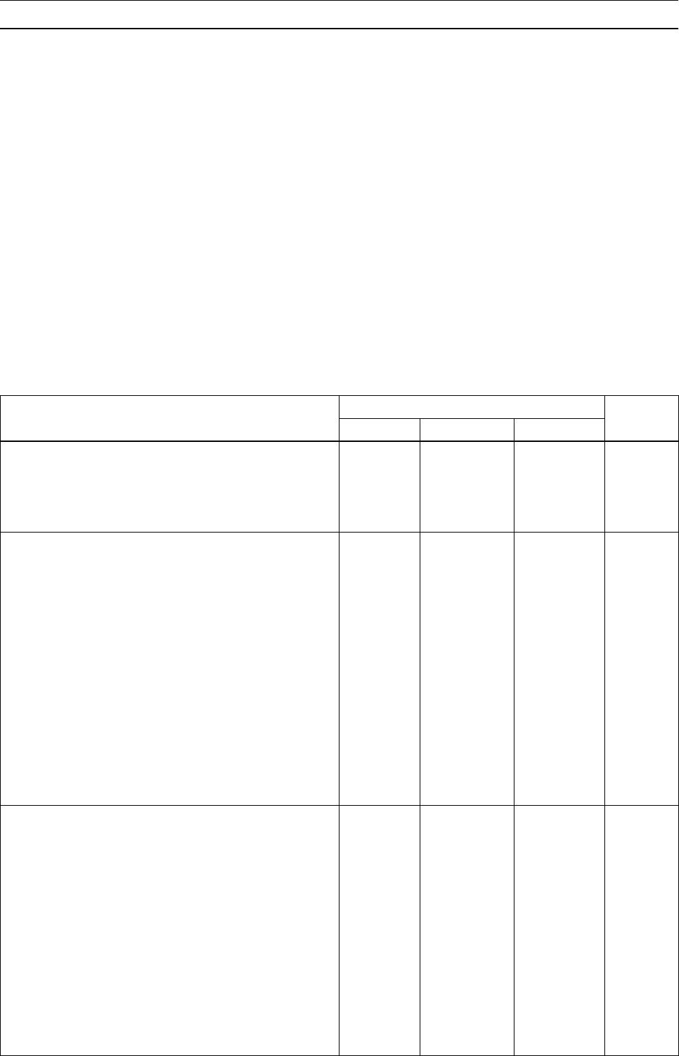
Periodic Maintenance Chart
Periodic Replacement Parts
FREQUENCY Whichever
come
first
* ODOMETER READING
× 1000 km
(× 1000 mile)
112 18 24 36 48
CHANGE/REPLACEMENT Every (0.6) (7.5) (12) (15) (24) (30)
See
Page
Fuel hose 4 years •2-40
Air cleaner element 2 years 2-40
Coolant 3 years •2-40
Radiator hose and O-ring 3 years •2-43
Engine oil # year • • • • • 2-43
Oil filter year • • • • • 2-44
Brake hose 4 years •2-44
Brake fluid 2 years • • 2-45
Master Cylinder/Caliper Rubber Parts 4 years •2-47
#: Service more frequently when operating in severe conditions; dusty, wet, muddy, high speed or
frequent starting/stopping.
*: For higher odometer readings, repeat at the frequency interval established here.
2-6 PERIODIC MAINTENANCE
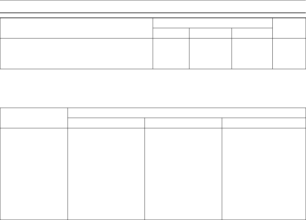
Torque and Locking Agent
Tighten all bolts and nuts to the proper torque using an accurate torque wrench. An insufficiently
tightened bolt or nut may become damaged or fall off, possibly resulting in damage to the motorcycle
and injury to the rider. A bolt or nut which is overtightened may become damaged, strip an internal
thread, or break and then fall out. The following table lists the tightening torque for the major bolts
and nuts, and the parts requiring use of a non-permanent locking agent or liquid gasket.
When checking the tightening torque of the bolts and nuts, first loosen the bolt or nut by half a turn
and then tighten it to the specified torque.
Letters used in the "Remarks" column mean:
EO: Apply engine oil to the threads and seating surface.
L: Apply a non-permanent locking agent to the threads.
LG: Apply liquid gasket to the threads.
Lh: Left-hand threads.
M: Apply molybdenum disulfide grease.
MO: Apply molybdenum disulfide oil (mixture of the engine oil and molybdenum disulfide grease in
a weight ratio 10 : 1)
R: Replacement parts.
S: Tighten the fasteners following the specified sequence.
SS: Apply silicone sealant to the threads.
St: Stake the fasteners to prevent loosening.
Torque
Fastener N·m kgf·m ft·lb Remarks
Fuel System
Fuel Tap Cover Screws 0.8 0.08 7in·lb
Fuel Tap Mounting Bolts 5.0 0.51 44 in·lb
Air Cut Valve Cover Screws 1.0 0.10 9in·lb
Cooling System
Radiator Hose Clamp Screws 2.5 0.25 22 in·lb
Radiator Fan Switch 18 1.8 13
Thermostat Housing Bolts 11 1.1 95 in·lb
Water Temperature Sensor 7.8 0.8 69 in·lb SS
Water Pump Cover Bolts 11 1.1 95 in·lb
Water Pump Shaft 25 2.5 18 Lh
Water Pump Impeller 9.8 1.0 87 in·lb Lh
Water Pipe Bolts 9.8 1.0 87 in·lb L
Cylinder Head Jacket Plug 9.8 1.0 87 in·lb L
Radiator Cap Holder Mounting Bolts 11 1.1 95 in·lb
Coolant Drain Plug 11 1.1 95 in·lb
Engine Top End
Air Suction Valve Cover Bolts 11 1.1 95 in·lb
Cylinder Head Cover Bolts 9.8 1.0 87 in·lb S
Camshaft Cap Bolts 12 1.2 104 in·lb S
Rocker Shafts 39 4.0 29 EO
Valve Adjuster Locknuts 25 2.5 18
Camshaft Sprocket Bolts 15 1.5 11 L
Cylinder Head Bolts (10 mm) 51 5.2 38 S
Cylinder Head Bolts (6 mm) 9.8 1.0 87 in·lb S
Camshaft Chain Tensioner Mounting Bolts 11 1.1 95 in·lb
Camshaft Chain Tensioner Cap Bolt 13 1.3 9.5

PERIODIC MAINTENANCE 2-7
Torque and Locking Agent
Torque
Fastener N·m kgf·m ft·lb Remarks
Main Oil Pipe Upper Banjo Bolts M8 12 1.2 104 in·lb
Main Oil Pipe Lower Banjo Bolt M10 20 2.0 14.5
Water Jacket Plug 9.8 1.0 87 in·lb L
Oil Pipe Bolts (in the cylinder head) 11 1.1 95 in·lb
Main Oil Pipe Mounting Bolt 11 1.1 95 in·lb
Clutch
Oil Filler Plug 1.5 0.15 13 in·lb
Clutch Hub Nut 132 13.5 98
Clutch Spring Bolts 9.3 0.95 82 in·lb
Clutch Cable Holder Bolt 11 1.1 95 in·lb
Clutch Cover Bolts 11 1.1 95 in·lb
Engine Lubrication System
Oil Filler Plug 1.5 0.15 13 in·lb
Oil Passage Plug 18 1.8 13
Oil Filter Mounting Stud 25 2.5 18 L
(Planted
side)
Oil Filter (Cartridge Type) 17 1.7 12.5
Oil Pipe for Balancer Shaft Banjo Bolt 20 2.0 14.5
Oil Pipe for Drive Shaft Upper Banjo Bolt M6 7.8 0.8 69 in·lb
Oil Pipe for Drive Shaft Lower Banjo Bolt M8 12 1.2 104 in·lb
Oil Pipe for Output Shaft Upper Banjo Bolt M6 7.8 0.8 69 in·lb
Oil Pipe for Output Shaft Lower Banjo Bolt M8 12 1.2 104 in·lb
Oil Pipe for Output Shaft Mounting Bolt 11 1.1 95 in·lb L
Oil Pump Outer Oil Pipe Bolts 11 1.1 95 in·lb L
Relief Valve 15 1.5 11 L
Oil Pressure Switch Terminal Bolt 1.5 0.15 13 in·lb
Oil Pressure Switch 15 1.5 11 SS
Main Oil Pipe Mounting Bolt 11 1.1 95 in·lb
Main Oil Pipe Upper Banjo Bolts 12 1.2 104 in·lb
Main Oil Pipe Lower Banjo Bolt 20 2.0 14.5
Rocker Shafts 39 4.0 29
Engine Oil Drain Plug 29 3.0 22
Oil Pan Mounting Bolts 11 1.1 95 in·lb
Oil Pump Mounting Bolts 11 1.1 95 in·lb
Engine Removal/Installation
Downtube Bolts 44 4.5 33
Engine Mounting Bolts and Nuts 44 4.5 33
Engine Mounting Bracket Bolts 25 2.5 18
Crankshaft/Transmission
Breather Body Bolt 5.9 0.6 52 in·lb
Crankcase Bolts (8 mm) 27 2.8 20 S
Crankcase Bolts (6 mm) 12 1.2 104 in·lb S

2-8 PERIODIC MAINTENANCE
Torque and Locking Agent
Torque
Fastener N·m kgf·m ft·lb Remarks
Upper Primary Chain Guide Mounting Bolt 11 1.1 95 in·lb L
Lower Primary Chain Guide Mounting Bolt 11 1.1 95 in·lb L
Connecting Rod Big End Nuts 36 3.7 27
Return Spring Pin 20 2.0 14.5 L
Gear Positioning Lever Pivot Stud – – – L
(planted
side)
Gear Positioning Lever Nut 11 1.1 95 in·lb
Shift Pedal Link Lever Mounting Bolt 12 1.2 104 in·lb
Shift Drum Bearing Holder Bolts 11 1.1 95 in·lb L
Shift Drum Cam Pin Plate Screw – – – L
Engine Sprocket Nut 127 13 94 EO
External Shift Mechanism Cover Bolts 11 1.1 95 in·lb
Neutral Switch 15 1.5 11
Wheels/Tires
Spoke Nipple 2.0 ∼3.9 0.2 ∼0.4 17 ∼35 in·lb
Front Axle Nut 88 9.0 65
Rear Sprocket Nut 33 3.4 24
Rear Axle Nut 108 11 80
Final Drive
Engine Sprocket Nut 127 13 94 EO
Rear Sprocket Nuts 33 3.4 24
Rear Coupling Studs – – – L
(planted
side)
Rear Axle Nut 108 11 80
Drive Chain Guide Bolts 11 1.1 95 in·lb
Brakes
Brake Hose Banjo Bolts 34 3.5 25
Front Reservoir Cap Screws 1.5 0.15 13 in·lb
Brake Lever Pivot Bolt 1.0 0.10 9in·lb
Brake Lever Pivot Locknut 5.9 0.60 52 in·lb
Front Master Cylinder Clamp Bolts 11 1.1 95 in·lb S
Front Brake Light Switch Mounting Screw 1.2 0.12 10 in·lb
Front Caliper Mounting Bolts 34 3.5 25
Rear Caliper Mounting Bolts 25 2.5 18
Caliper Bleed Valves 7.8 0.8 69 in·lb
Brake Disc Mounting Bolts 23 2.3 16.5 L
Brake Pedal Bolt 25 2.5 18
Rear Reservoir Mounting Bolt 5.9 0.60 52 in·lb
Rear Master Cylinder Mounting Bolts 25 2.5 18
Suspension
Front Fork Upper Clamp Allen Bolts 25 2.5 18 S
Front Fork Lower Clamp Bolts 23 2.3 16.5 S

PERIODIC MAINTENANCE 2-9
Torque and Locking Agent
Torque
Fastener N·m kgf·m ft·lb Remarks
Front Fork Top Bolts 30 3.1 22
Front Fork Bottom Allen Bolt 30 3.1 22 L
Rear Shock Absorber Upper Mounting Nut 59 6.0 43
Rear Shock Absorber Lower Mounting Nut 98 10 72
Swingarm Pivot Nut 118 12 87
Rocker Arm Pivot Nut 98 10 72
Tie-Rod Mounting Nuts 98 10 72
Steering
Handlebar Clamp Bolts 25 2.5 18 S
Handlebar Weight Allen Bolts – – – L
Front Fork Upper Clamp Allen Bolts 25 2.5 18 S
Front Fork Lower Clamp Bolts 23 2.3 16.5 S
Steering Stem Head Nut 39 4.0 29
Steering Stem Locknut Hand
-Tighten
Hand
-Tighten
Hand
-Tighten
(about 4.9) (about 0.5) (about 43
in·lb)
Frame
Tail Grip Bolts 25 2.5 18
Front Footpeg Bracket Bolts 34 3.5 25
Sidestand Bolt and Nut 44 4.5 33
Rear Footpeg Bracket Bolts 25 2.5 18
Carrier Stay Mounting Bolts 25 2.5 18
Electrical System
Crankshaft Sensor Mounting Screws 8.3 0.85 74 in·lb L
Timing Inspection Plug 2.5 0.25 22 in·lb
Alternator Rotor Bolt Plug 1.5 0.15 13 in·lb
Alternator Cover Bolts 11 1.1 95 in·lb
Alternator Lead Clamp Screws 2.9 0.30 26 in·lb
Spark Plug 14 1.4 10
Alternator Stator Allen Bolts 12 1.2 104 in·lb
Alternator Rotor Bolt 69 7.0 51 Lh
Starter Motor Mounting Bolts 11 1.1 95 in·lb
Starter Chain Guide Bolts 4.9 0.5 43 in·lb L
Starter Motor Through Bolts 6.9 0.7 65 in·lb
Starter Motor Terminal Nut 4.9 0.5 43 in·lb
Starter Motor Lead Clamp Nut 4.9 0.5 43 in·lb
Starter Clutch Allen Bolts 34 3.5 25 L
Sidestand Switch Mounting Screw 3.9 0.4 35 in·lb L
Sidestand Bolt and Nut 44 4.5 33
Radiator Fan Switch 18 1.8 13
Water Temperature Switch 7.8 0.80 69 in·lb SS
Oil Pressure Switch Terminal Bolt 1.5 0.15 13 in·lb
2-10 PERIODIC MAINTENANCE
Torque and Locking Agent
Torque
Fastener N·m kgf·m ft·lb Remarks
Oil Pressure Switch 15 1.5 11 SS
Neutral Switch 15 1.5 11
Tail Light Mounting Nut 5.9 0.6 52 in·lb
The table relating tightening torque to thread diameter, lists the basic torque for the bolts and nuts.
Use this table for only the bolts and nuts which do not require a specific torque value. All of the values
are for use with dry solvent-cleaned threads.
Basic Torque for General Fasteners
Threads Torque
dia. (mm) N·m kgf·m ft·lb
53.4 ∼4.9 0.35 ∼0.50 30 ∼43 in·lb
65.9 ∼7.8 0.60 ∼0.80 52 ∼69 in·lb
814 ∼19 1.4 ∼1.9 10.0 ∼13.5
10 25 ∼34 2.6 ∼3.5 19.0 ∼25
12 44 ∼61 4.5 ∼6.2 33 ∼45
14 73 ∼98 7.4 ∼10.0 54 ∼72
16 115 ∼155 11.5 ∼16.0 83 ∼115
18 165 ∼225 17.0 ∼23.0 125 ∼165
20 225 ∼325 23 ∼33 165 ∼240

PERIODIC MAINTENANCE 2-11
Specifications
Item Standard Service Limit
Fuel System
ThrottleGripFreePlay 2∼3 mm (0.08 ∼0.12 in.) –––
Idle Speed 1 200 ±50 r/min (rpm) –––
Engine Top End
Valve Clearance
Inlet 0.13 ∼0.18 mm (0.0051 ∼0.0071 in.) –––
Exhaust 0.18 ∼0.23 mm (0.0070 ∼0.0090 in.) –––
Clutch
Clutch Lever Free Play 2∼3 mm (0.08 ∼0.12 in.) –––
Wheels/Tires
Air Pressure
Front 150 kPa (1.5 kgf/cm², 21 psi) –––
Rear 225 kPa (2.25 kgf/cm², 32 psi) –––
Tread Depth
Front
Dunlop 6.9 mm (0.27 in.) 1 mm (0.04 in.)
Bridgestone 6.0 mm (0.24 in.)
Rear
Dunlop 8.8 mm (0.35 in.) 2 mm (0.08 in.)
(Up to 130 km/h
(80 mph))
Bridgestone 8.5 mm (0.33 in.) 3 mm (0.12 in.)
(Over to 130 km/h
(80 mph))
Rim Runout
Axial 0.5 mm (0.02 in.) 1.5 mm (0.06 in.)
Radial 0.8 mm (0.03 in.) 1.5 mm (0.06 in.)
Final Drive
Drive Chain Slack 2∼12 mm (0.08 ∼0.47 in.) –––
Drive Chain Wear (20-link length) 317.5 ∼318.2 mm (12.50 ∼12.53 in.) 323 mm (12.7 in.)
Brakes
Brake Fluid Grade DOT4 –––
Pad Lining Thickness 5.5 mm (0.203 in.) 1 mm (0.04 in.)
Brake Light Timing
Front ON after 10 mm (0.39 in.) lever travel –––
Rear ON after 15 mm (0.59 in.) pedal travel –––
Electrical System
Spark Plug Gap 0.6 ∼0.7 mm (0.024 ∼0.028 in.) –––
Replacement Parts
Coolant Capacity 1.7 L (1.8 US qt) –––
Engine Oil
Grade API SE, SF, SG or
API SH or SJ with JASO MA –––
Viscosity SAE10W-40 –––
2-12 PERIODIC MAINTENANCE
Specifications
Item Standard Service Limit
Capacity
when filter is not removed 2.8L(3.0USqt) –––
when filter is removed 3.0L(3.2USqt) –––
when engine is completely dry 3.4L(3.6USqt) –––
PERIODIC MAINTENANCE 2-13
Special Tools
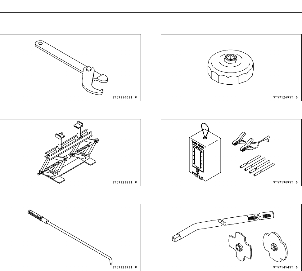
Steering Stem Nut Wrench:
57001-1100
Jack:
57001-1238
Pilot Screw Adjuster, A:
57001-1239
Oil Filter Wrench:
57001-1249
Vacuum Gauge:
57001-1369
Filler Cap Driver:
57001-1454
2-14 PERIODIC MAINTENANCE
Maintenance Procedure
Fuel System
Throttle Cable Inspection
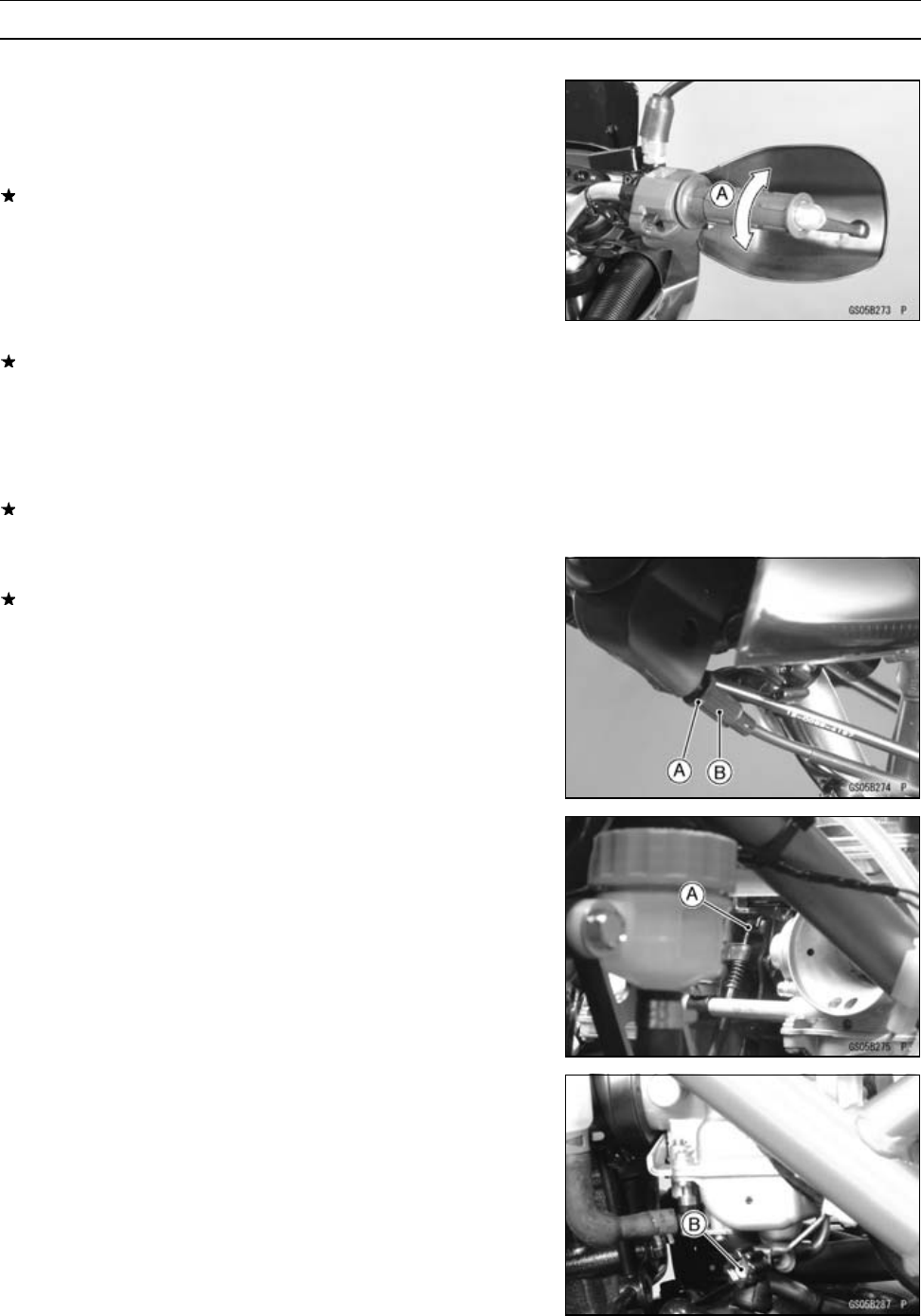
Throttle Grip Free Play Inspection
•Check throttle grip play [A] by lightly turning the throttle
grip back and forth.
If the free play is improper, adjust the throttle cable.
Throttle Grip Free Play
Standard: 2 ∼3 mm (0.08 ∼0.12 in.)
•Check that the throttle grip moves smoothly from full open
to close, and the throttle closes quickly and completely in
all steering positions by the return spring.
If the throttle grip does not return properly, check the throt-
tle cable routing, grip free play, and cable damage. Then
lubricate the throttle cable.
•Run the engine at the idle speed, and turn the handlebar
all the way to the right and left to ensure that the idle speed
does not change.
If the idle speed increase, check the throttle cable free
play and the cable routing.
Throttle Grip Free Play Adjustment
If the free play is incorrect, loosen the locknut [A] and turn
the adjuster [B] of the accelerator cable until the 2 ∼3mm
(0.08 ∼0.12 in.) of throttle grip play is obtained.
•Tighten the locknut against the adjuster securely.
•Check that the throttle pulley [A] stops against the idle
adjusting screw [B] with the throttle grip closed.
PERIODIC MAINTENANCE 2-15
Maintenance Procedure
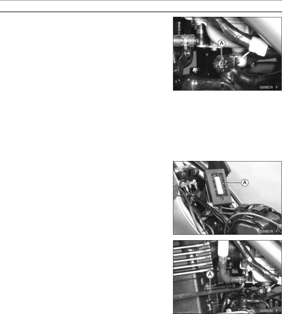
If the play can not be adjusted by using the adjuster at the
throttle grip, use the adjuster [A] of the decelerator cable
under the fuel tank.
•Screw in the adjuster fully at the throttle grip and tighten
the locknut.
•Remove the fuel tank (see Fuel Tank Removal in the Fuel
System chapter).
○Make the necessary free play adjustment at the lower ca-
ble end.
•Check that the throttle pulley stops [A] against the idle
adjusting screw [B], with the throttle grip released and
stops against the carburetor stopper with the throttle grip
opened.
•Turn the handlebar from side to side while idling the en-
gine.
If idle speed varies, the cable may be poorly routed or
damaged.
WARNING
Operation with an improperly adjusted, incorrectly
routed, or damaged cable could result in an unsafe
riding condition.
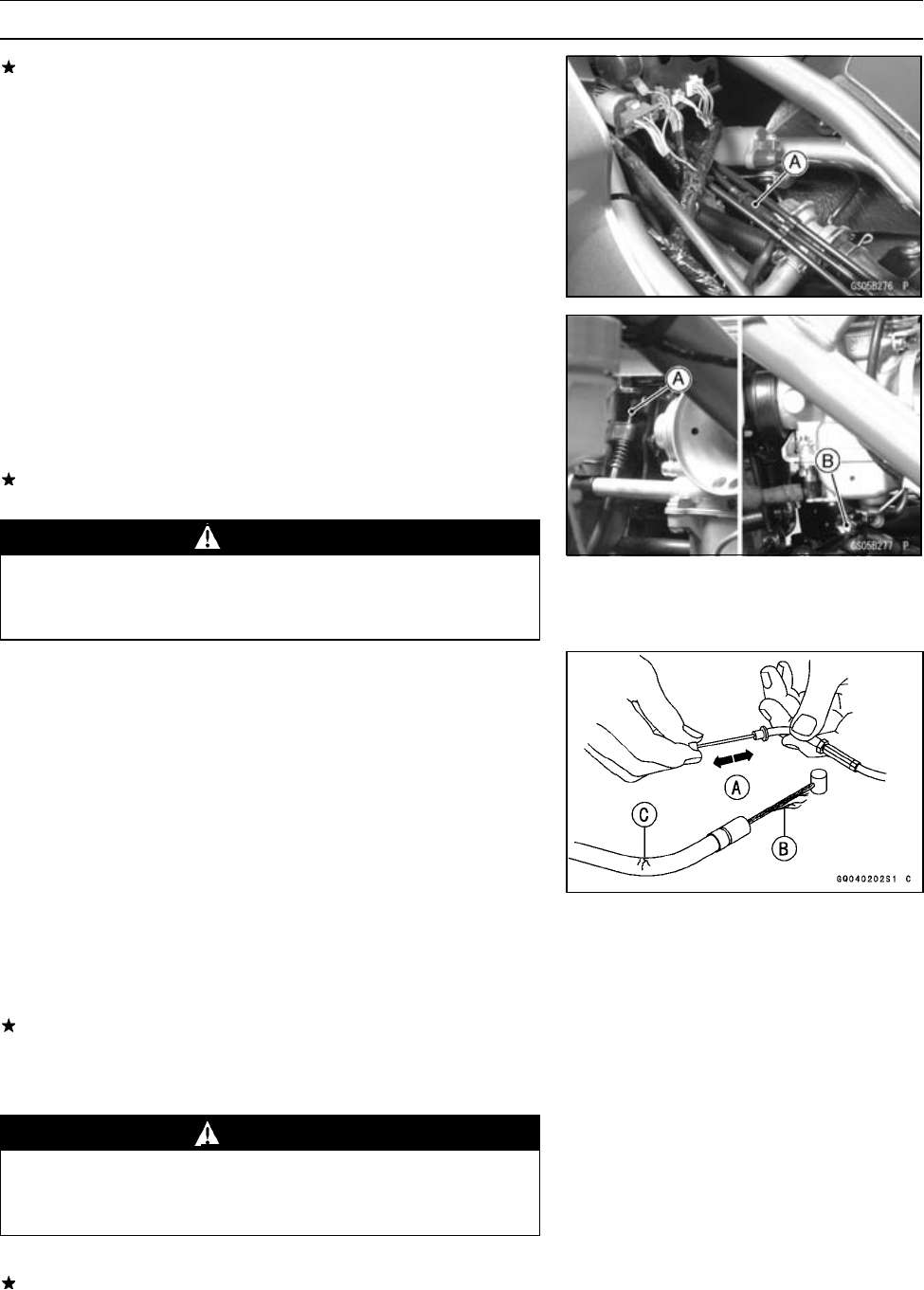
Throttle Cable Inspection
•Remove both ends of the throttle cables.
•With the throttle cable disconnected at both ends, the ca-
ble should move freely [A] within the cable housing.
○If cable movement is not free after lubricating, if the cable
is frayed [B], or if the cable housing is kinked [C], replace
the cable.
Idle Speed Inspection
Idle Speed Inspection
•Start the engine and warm it up thoroughly.
•With the engine idling, turn the handlebar to both sides.
If handlebar movement changes the idle speed, the throt-
tle cable may be improperly adjusted or incorrectly routed,
or it may be damaged. Be sure to correct any of these
conditions before riding.
WARNING
Operation with improperly adjusted, incorrectly
routed, or damaged cables could result in an un-
safe riding condition.
•Check idle speed.
If the idle speed is out of the specified range, adjust it.
Idle Speed
1 200 ±50 r/min (rpm)
2-16 PERIODIC MAINTENANCE
Maintenance Procedure
Idle Speed Adjustment
•Start the engine and warm it up thoroughly.
•Turn the adjusting screw [A] until idle speed is correct.
○Open and close the throttle a few times to make sure that
the idle speed is within the specified range. Readjust if
necessary.
Carburetor Synchronization Inspection
Synchronization Inspection
•Situate the motorcycle so that it is perpendicular to the
ground.
•Remove the fuel tank and connect the auxiliary fuel tank
to supply the fuel.
•Warm up the engine.
•Check idle speed and adjust if necessary.
•Pull the vacuum hoses off, and attach vacuum gauge [A]
to the vacuum hose fittings on the carburetors.
Special Tool - Vacuum Gauge: 57001-1369
Synchronization Adjustment
○The pilot screw is set at the factory and should not be
removed. But if necessary, check the pilot screw opening
as follows.
•Turn in the pilot screw and count the number of turns until
it seats fully but not tightly, and then remove the screw.
This is to set the screw to its original (correct) position
when assembling.
Special Tool - Pilot Screw Adjuster, C [A]: 57001-1239
NOTE
○Each carburetor has different opening of the pilot screw.
When setting the pilot screw, do not refer to the specifi-
cations which show mean opening of the pilot screws.
PERIODIC MAINTENANCE 2-17
Maintenance Procedure
Coolant Filter Cleaning
○Before winter season starts, clean the coolant filter [A] in
the carburetor system.
•Drain the coolant (see Coolant Draining).
•Remove the coolant filter from the cooling hoses in the
carburetor system.
•Blow dirt and sediment off the filter with compressed air.
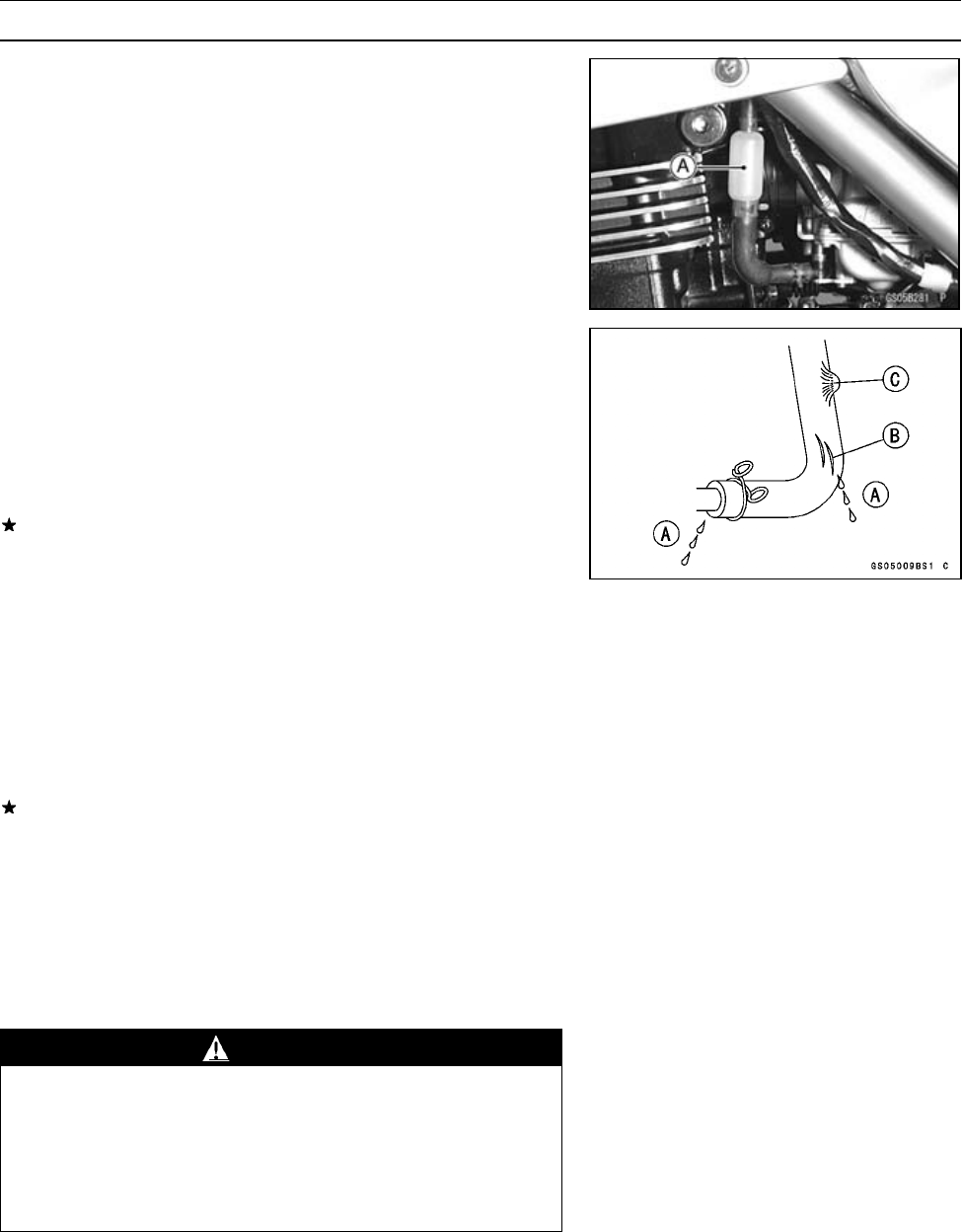
Fuel Hoses and Connections Check
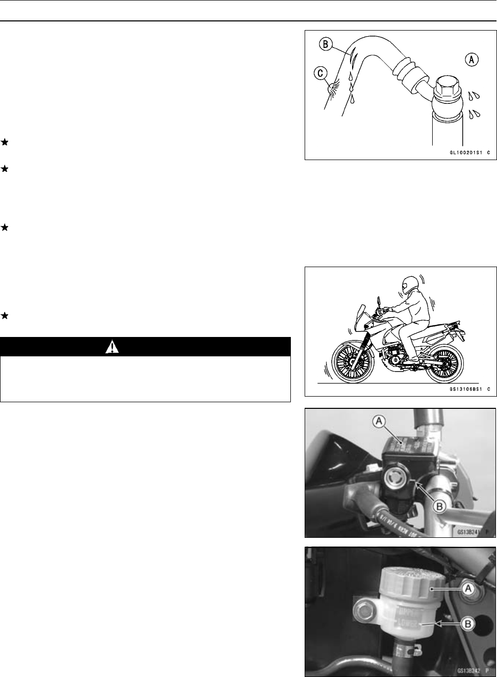
○The fuel hoses are designed to be used throughout the
motorcycle’s life without any maintenance, however, if the
motorcycle is not properly handled, the high pressure in-
side the fuel line can cause fuel to leak [A] or the hose to
burst. Remove the fuel tank (see Fuel Tank Removal in
the Fuel System chapter) and check the fuel hose.
Replace the fuel hose if any fraying, cracks [B] or bulges
[C] are noticed.
•Check that the hoses are securely connected and clamps
are tightened correctly.
•When installing, route the hoses according to Cable,
Wire, and Hose Routing section in the General Informa-
tion chapter.
•When installing the fuel hoses, avoid sharp bending, kink-
ing, flattening or twisting, and route the fuel hoses with a
minimum of bending so that the fuel flow will not be ob-
structed.
Replace the hose if it has been sharply bent or kinked.
Air Cleaner Element Cleaning and Inspection
NOTE
○In dusty areas, the element should be cleaned more
frequently than the recommended interval.
○After riding through rain or on muddy roads, the element
should be cleaned immediately.
WARNING
Clean the element in a well-ventilated area, and
make sure that there are no sparks or flame any-
where near the working area. Because of the
danger of highly flammable liquids, do not use
gasoline or a low-flash point solvent to clean the
element.
2-18 PERIODIC MAINTENANCE
Maintenance Procedure
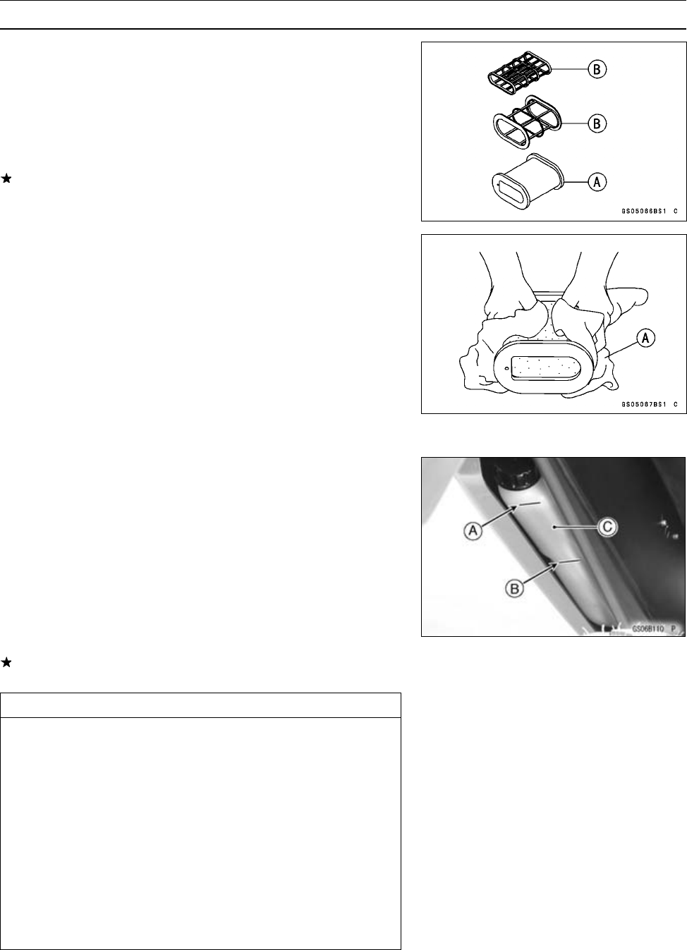
•Remove the element assembly from the air cleaner hous-
ing (see Air Cleaner Element Removal in the Fuel System
chapter).
•Separate the element [A] from the element holders [B].
•Clean the element in a bath of high-flash point solvent,
and then dry it with compressed air or by shaking it.
•Visually check the element for tear or breaks.
If any of the parts of the element are damaged, replace
them with a new one.
•After cleaning of the element, saturate it with high quality
form air filter oil and squeeze out excess oil.
•Wrap the element [A] in a clean rag [B] and squeeze it as
dry as possible.
•Assemble the element with the holders, and install them
into the air cleaner housing.
Cooling System
Coolant Level Inspection
•Situate the motorcycle so that it is perpendicular to the
ground.
•Check the level through the coolant level gauge on the
reservoir tank [C]. The coolant level should be between
the "H" (High) [A] and the "L" (Low) [B] level lines.
NOTE
○Check the level when the engine is cold (room or ambi-
ent temperature).
If the coolant level is lower than the "L" (Low) level line,
add coolant to the "F" (Full) level line.
CAUTION
For refilling, add the specified mixture of coolant
and soft water. Adding water alone dilutes the
coolant and degrades its anticorrosion properties.
The diluted coolant can attack the aluminum en-
gine parts. In an emergency, soft water alone can
be added. But the diluted coolant must be returned
to the correct mixture ratio within a few days. If
coolant must be added often, or the reserve tank
has run completely dry, there is probably leakage
in the cooling system. Check the system for leaks
(see Visual Leak Inspection, and Cooling System
Pressure Testing).
PERIODIC MAINTENANCE 2-19
Maintenance Procedure
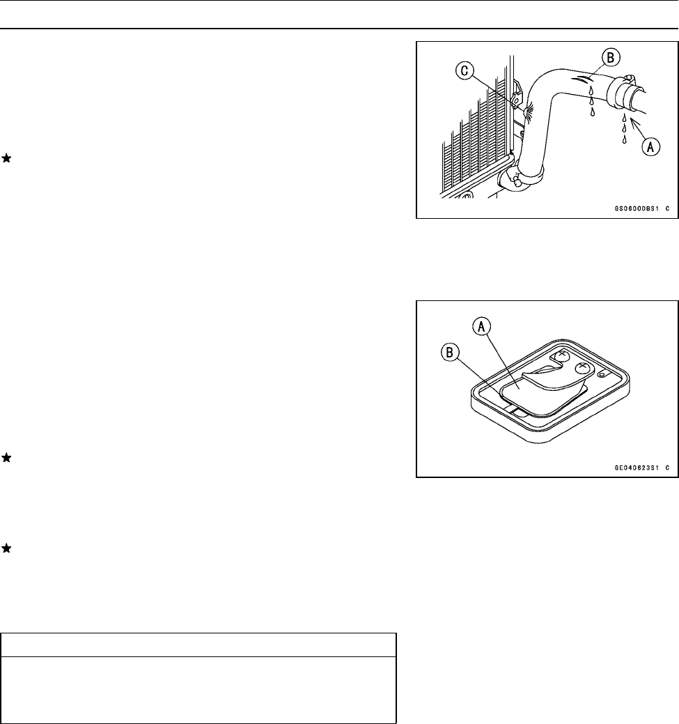
Radiator Hoses and Connections Inspection
○The high pressure inside the radiator hose can cause
coolant to leak [A] or the hose to burst if the line is not
properly maintained. Visually inspect the hoses for signs
of deterioration. Squeeze the hoses. A hose should not
be hard and brittle, nor should it be soft or swollen.
Replace the hose if any fraying, cracks [B] or bulges [C]
are noticed.
•Check that the hoses are securely connected and clamps
are tightened correctly.
Torque - Radiator Hose Clamp Screws: 2.5 N·m (0.25 kgf·m,
22 in·lb)
Engine Top End
Air Suction Valve Inspection
The air suction valve is essentially a check valve which
allows fresh air to flow from the air cleaner into the exhaust
port. Any air that has passed the air suction valve is pre-
vented from returning to the air cleaner.
•Remove the air suction valves.
•Visually inspect the reeds [A] for cracks, folds, warps,
heat damage, or other damage.
If there is any doubt as to the condition of the reed, replace
the air suction valve as an assembly.
•Check the reed contact areas [B] of the valve holder for
grooves, scratches, any signs of separation from the
holder, or heat damage.
If there is any doubt as to the condition of the reed contact
areas, replace the air suction valve as an assembly.
•If any carbon or other foreign particles have accumulated
between the reed and the reed contact area, wash the
valve assembly clean with a high flash-point solvent.
CAUTION
Do not scrape off the deposits with a scraper as this
could damage the rubber, requiring replacement of
the suction valve assembly.
Valve Clearance Inspection
Valve Clearance Inspection
NOTE
○Valve clearance must be checked and adjusted when
the engine is cold (room temperature).
•Remove the cylinder head cover (see Cylinder Head
Cover Removal in the Engine Top End chapter).
•Remove the cylinder head oil pipes (see Cylinder Head
Oil Pipe Removal in the Engine Top End chapter).
2-20 PERIODIC MAINTENANCE
Maintenance Procedure
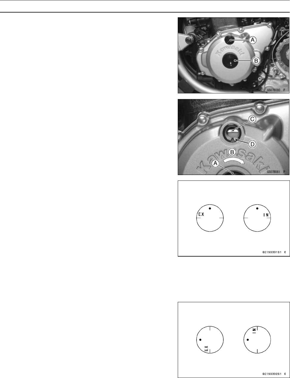
•Unscrew the upper [A] and lower [B] caps on the alterna-
tor cover.
Special Tool - Filler Cap Driver: 57001-1454
•Check the valve clearance when the pistons are at TDC.
○The pistons are numbered beginning with the engine left
side.
•Using a wrench on the crankshaft rotation bolt [A], turn
the crankshaft clockwise [B] until the "C" mark [C] on the
rotor is aligned with the notch [D] in the edge of the upper
hole in the alternator cover for #2 piston and "T" mark for
#1 piston.
○Measure the valve clearance of the valves for which the
cam lobe is pointing away from the rocker arm.
•Each piston has two inlet and two exhaust valves. Mea-
sure these two inlet or exhaust valves at the same crank-
shaft position.
Valve Clearance Measuring Position
#2 Piston TDC at End of Compression Stroke →
Inlet valve clearances of #2 piston, and
Exhaust valve clearances of #2 piston
NOTE
○Check the valve clearance using this method only.
Checking the clearance at any other cam position may
result in improper valve clearance.
Valve Clearance Measuring Position
#1 Piston TDC at End of Compression Stroke →
Inlet valve clearances of #1 piston, and
Exhaust valve clearances of #1 piston
PERIODIC MAINTENANCE 2-21
Maintenance Procedure
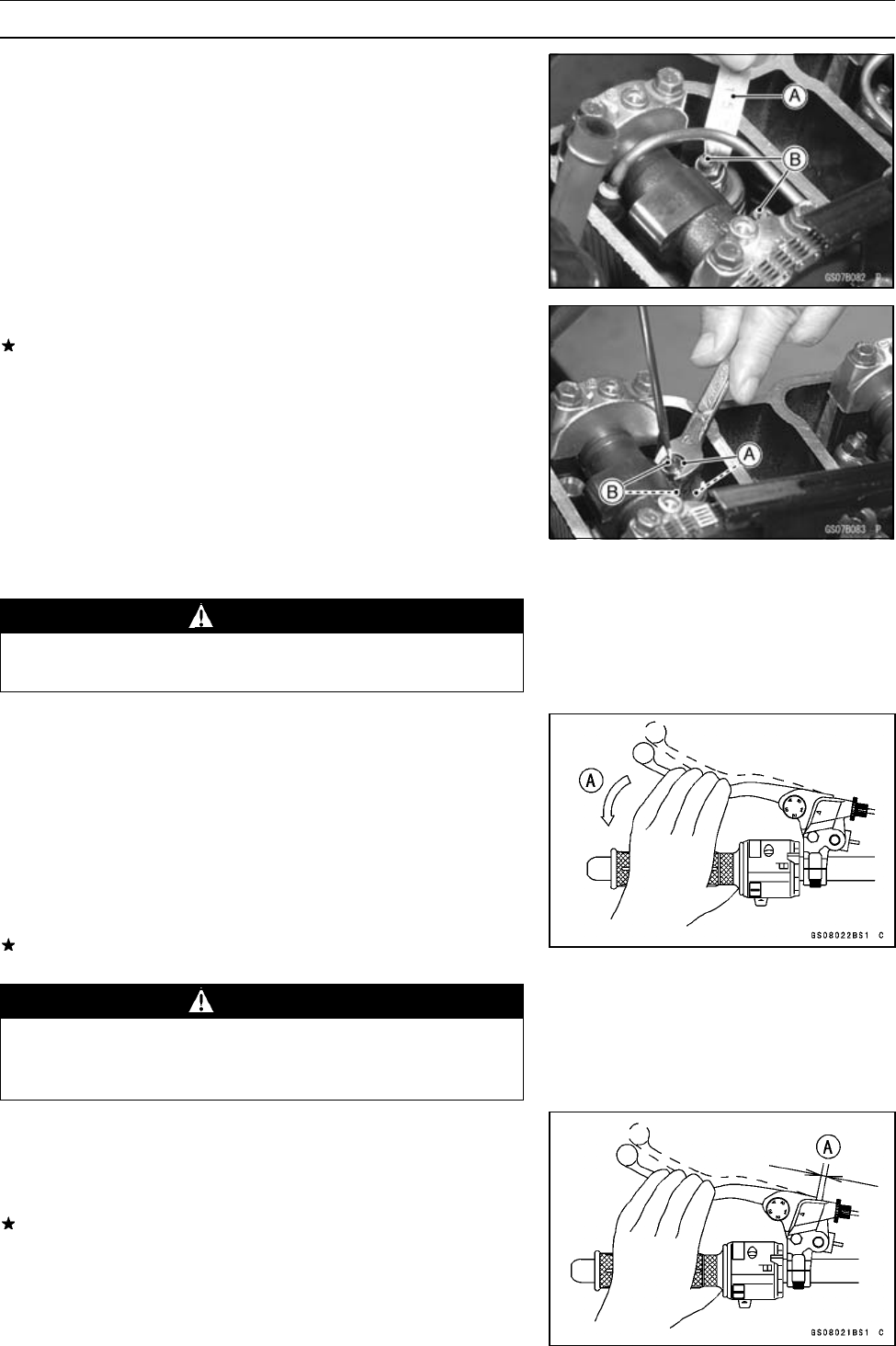
•Measure the clearance of each valve by inserting a thick-
ness gauge [A] between the adjusting screw [B] and the
valve stem.
Valve Clearance (when cold)
Inlet 0.13 ∼0.18 mm (0.0051 ∼0.0071 in.)
Exhaust 0.18 ∼0.23 mm (0.0070 ∼0.0090 in.)
Valve Clearance Adjustment
If the valve clearance is incorrect, loosen the locknut [A]
and turn the adjusting screw [B] until the correct clearance
is obtained.
•Tighten the locknut.
Torque - Valve Adjuster Locknuts: 25 N·m (2.5 kgf·m, 18
ft·lb)
•Install the two caps on the alternator cover.
Clutch
WARNING
To avoid a serious burn, never touch the engine or
exhaust pipe during clutch adjustment.
Clutch Operation Inspection
Clutch Operation Inspection
•With the engine idling, make sure that there is no noise
or abnormally heavy feeling when pulling [A] in the clutch
lever fully. Also, make sure that the shift lever operates
smoothly.
•When moving off the motorcycle by releasing the clutch
lever gradually, make sure that the clutch does not slip
and that the clutch engages smoothly.
If the clutch operation is insufficiency, inspect the clutch
system.
WARNING
When inspecting by running the vehicle, note a
surrounding traffic situation enough in the place of
safety.
Clutch Lever Free Play Inspection
•Pull the clutch lever just enough to take up the free play
[A].
•Measure the gap between the lever and the lever holder.
If the gap is too wide, the clutch may not release fully. If
the gap is too narrow, the clutch may not engage fully. In
either case, adjust the clutch.
Clutch Lever Free Play
Standard: 2 ∼3 mm (0.08 ∼0.12 in.)
2-22 PERIODIC MAINTENANCE
Maintenance Procedure
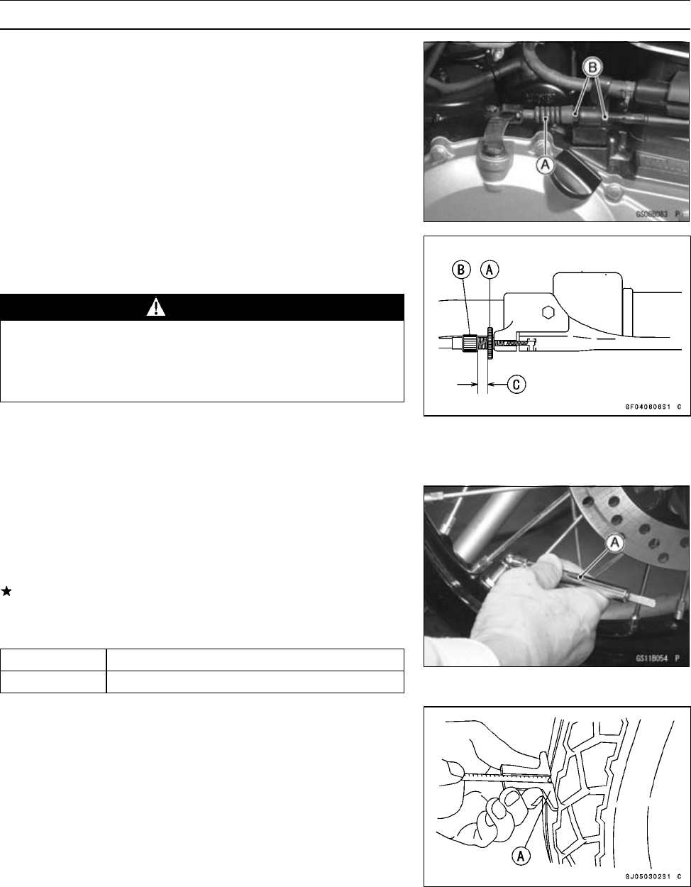
Clutch Lever Free Play Adjustment
•Slide back the dust cover [A].
•Loosen both adjuster nuts [B] at the right hand crankcase
as far as they will go.
•Loosen the knurled locknut [A] at the clutch lever.
•Turn the adjuster [B] so that 5 ∼6 mm (0.20 ∼0.24 in.) [C]
of threads are visible.
WARNING
Be sure that the outer cable end at the clutch lever
is fully seated in the adjuster at the clutch lever, or
it could slip into the place later, creating enough
cable play to prevent clutch disengagement.
•After the adjustment is made, start the engine and check
that the clutch does not slip and that it releases properly.
Wheels/Tires
Air Pressure Inspection/Adjustment
•Measure the tire air pressure with an air pressure gauge
[A] when the tires are cold (that is, when the motorcycle
has not been ridden more than a mile during the past 3
hours).
Adjust the tire air pressure according to the specifications
if necessary.
Air Pressure (when cold)
Front 150 kPa (1.5 kgf/cm², 21 psi)
Rear 225kPa(2.25kgf/cm²,32psi)
Tire Tread Wear Inspection
As the tire tread wears down, the tire becomes more sus-
ceptible to puncture and failure. An accepted estimate is
that 90% of all tire failures occur during the last 10% of tread
life (90% worn). So it is false economy and unsafe to use
the tires until they are bald.
•Measure the tread depth at the center of the tread with a
depth gauge [A]. Since the tire may wear unevenly, take
measurement at several places.
PERIODIC MAINTENANCE 2-23
Maintenance Procedure
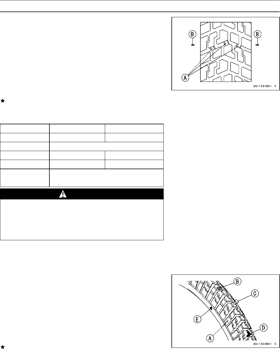
Wear Indicator [A]
Wear Indicator Position Mark [B]
If any measurement is less than the service limit, replace
the tire.
Tread Depth
Front DUNLOP BRIDGESTONE
Standard 6.9 mm (0.27 in.) 6.0 mm (0.24 in.)
Service Limit 1 mm (0.04 in.)
Rear DUNLOP BRIDGESTONE
Standard 8.8 mm (0.35 in.) 8.5 mm (0.33 in.)
Service Limit 2 mm (0.08 in.)(Up to 130 km/h (80 mph))
3 mm (0.12 in.)(Over 130 km/h (80 mph))
WARNING
To ensure safe handling and stability, use only the
recommended standard tires for replacement, in-
flated to the standard pressure.
Use the same manufacturer’s tires on both front and
rear wheels.
NOTE
○Check and balance the wheel when a tire is replaced
with a new one.
Wheel/Tire Damage Inspection
•Remove any imbedded stones [D], nail [C] or other foreign
particles from the tread.
Wear Indicator [E]
•Visually inspect the tire for cracks [A] and cuts [B], and re-
place the tire if necessary. Swelling or high spots indicate
internal damage, requiring tire replacement.
•Visually inspect the wheel for cracks, cuts and dents dam-
age.
If any damage is found, replace the wheel if necessary.
2-24 PERIODIC MAINTENANCE
Maintenance Procedure
Wheel Bearing Damage Inspection
•Using a jack and attachment, raise the front wheel off the
ground (see Wheels/Tires chapter).
•Turn the handlebar all the way to the right or left.
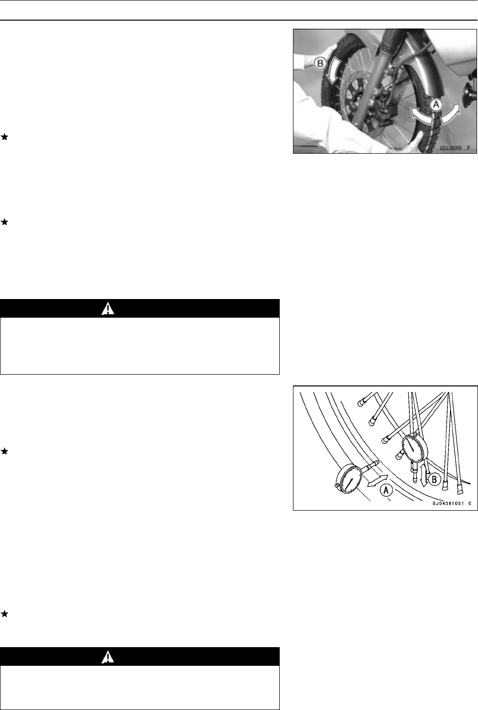
•Inspect the roughness of the front wheel bearing by push-
ing and pulling [A] the wheel.
•Spin [B] the front wheel lightly, and check for smoothly
turn, roughness, binding or noise.
If roughness, binding or noise is found, remove the front
wheel and inspect the wheel bearing (see Hub Bearing
Inspection in the Wheels/Tires chapter).
Spoke Tightness and Rim Runout Inspection
Spoke Tightness Inspection
•Check whether all the spokes are uniformly tightened.
Uniformly tighten the spokes if any spoke is loose or un-
evenly tightened.
Torque - Spoke Nipple: 3.0 N·m (0.3 kgf·m, 26 in·lb)
(On and after EJ650-A3/C3): 5.1 N·m (0.52 kgf·m,
45 in·lb)
•Inspect the rims.
WARNING
If any spoke brakes, it should be replaced immedi-
ately. A missing spoke places an additional load on
the other spokes, which will eventually cause other
spokes to break.
Rim Runout Inspection
•Raise the front/rear wheel of the ground.
Special Tool - Jack: 57001-1238
•Check the rim for damage or warpage.
If there is any damage to the rim, replace the rim.
•Measure the radial [A] and axial [B] rim runout by placing a
dial gauge against the sides and the outer circumference
of the rim, and slowly rotating the wheel.
Rim Runout (with tire installed)
Standard:
Axial Runout 0.5 mm (0.02 in.)
Radial Runout 0.8 mm (0.03 in.)
Service Limit:
Axial Runout 1.5 mm (0.06 in.)
Radial Runout 1.5 mm (0.06 in.)
If rim runout exceeds the service limit, inspect the hub
bearings. If the problem is not due to the bearings,
retighten the spokes.
WARNING
Never attempt to repair a damaged wheel part. If
the wheel part is damaged, it must be replaced with
a new part.
PERIODIC MAINTENANCE 2-25
Maintenance Procedure
Final Drive
Drive Chain Slack Inspection
Drive Chain Slack Inspection
NOTE
○Check the slack with the motorcycle setting on its side
stand.
○Clean the chain if it is dirty, and lubricate it if it appears
dry.
•Check the wheel alignment (see Wheel Alignment Inspec-
tion/Adjustment).
•Rotate the rear wheel to find the position where the chain
is tightest.
•Measure the vertical movement (chain slack) [A] midway
between the sprockets.
If the chain slack exceeds the standard, adjust it.
Chain Slack
Standard: 35 ∼45 mm (1.4 ∼1.8 in.)
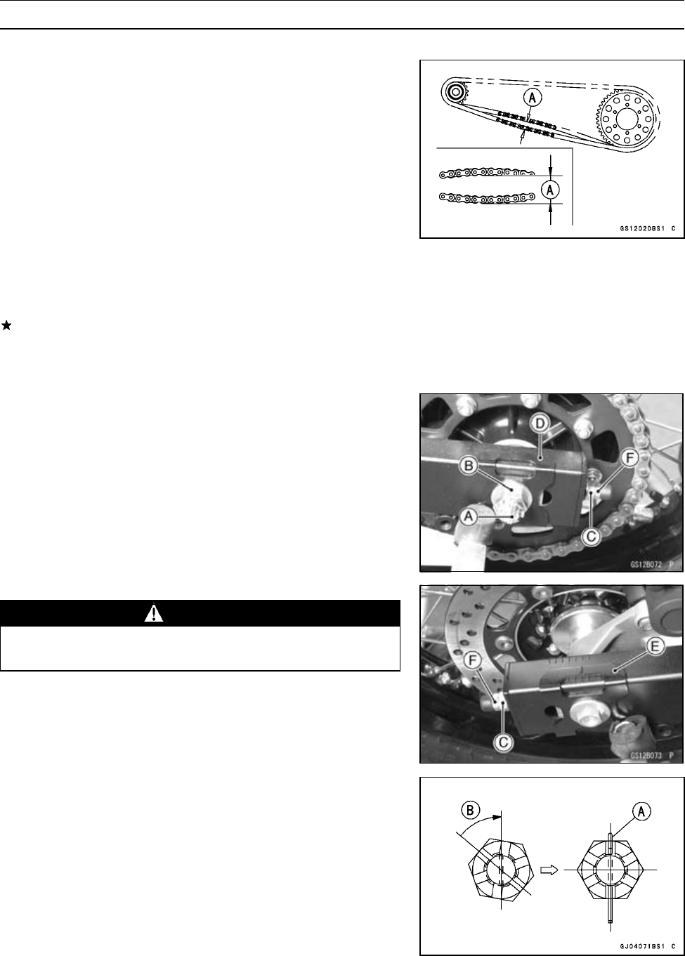
Drive Chain Slack Adjustment
•Remove:
Cotter Pin [A]
•Loosen:
Axle Nut [B]
Chain Adjuster Locknuts [F] (both sides)
•Turn the chain adjusting nuts [C] forward or rearward un-
til the drive chain has the correct amount of chain slack.
To keep the chain and wheel properly aligned, the left ad-
juster mark [D] position should align with the same grad-
uation that the right adjuster mark [E] position aligns with.
WARNING
Misalignment of the wheel will result in abnormal
wear and may result in an unsafe riding condition.
•Tighten both chain adjuster locknuts securely.
•Tighten the axle nut (see Front/Rear Wheel Installation in
the Wheels/Tires chapter).
Torque - Rear Axle Nut: 108 N·m (11 kgf·m, 80 ft·lb)
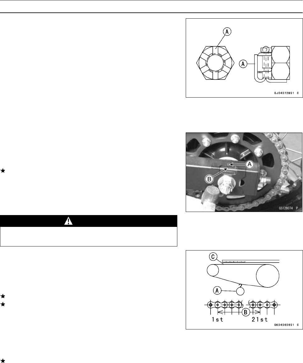
•Insert a the new cotter pin [A].
NOTE
○When inserting the cotter pin, if the slots in the nut do
not align with the cotter pin hole in the axle shaft, tighten
the nut clockwise [A] up to next alignment.
○It should be within 30 degree.
○Loosen once and tighten again when the slot goes past
the nearest hole.
2-26 PERIODIC MAINTENANCE
Maintenance Procedure
•Bend the cotter pin [A] over the nut.
•Turn the wheel, measure the chain slack again at the tight-
est position, and readjust if necessary.
•Check the rear brake.
Wheel Alignment Inspection/Adjustment
•Check that the left adjuster mark [A] position should align
with the same graduation [B] that the right adjuster mark
position aligns with.
If they do not, adjust the chain slack and align the wheel
alignment.
NOTE
○Wheel alignment can also be checked using the
straightedge or string method.
WARNING
Misalignment of the wheel will result in abnormal
wear, and may result in an unsafe riding condition.
Drive Chain Wear Inspection
•Remove:
Chain Cover
•Rotate the rear wheel to inspect the drive chain for dam-
aged rollers, loose pins and links.
If there is any irregularity, replace the drive chain.
Lubricate the drive chain if it appears dry.
•Stretch the chain taut by hanging a 98 N (10 kg, 20 lb)
weight [A] on the chain.
•Measure the length of 20 links [B] on the straight part [C] of
the chain from the pin center of the 1st pin to the pin center
of the 21st pin. Since the chain may wear unevenly, take
measurements at several places.
If any measurements exceed the service limit, replace the
chain. Also, replace the front and rear sprockets when the
drive chain is replaced.
Drive Chain 20-link Length
Standard: 317.5 ∼318.2 mm (12.50 ∼12.53 in.)
Service Limit: 323 mm (12.7 in.)
PERIODIC MAINTENANCE 2-27
Maintenance Procedure
WARNING
If the drive chain wear exceeds the service limit, re-
place the chain or an unsafe riding condition may
result. A chain that breaks or jumps off the sprock-
ets could snag on the engine sprocket or lock the
rear wheel, severely damaging the motorcycle and
causing it to go out of control.
For safely, use only the standard chain. It is an end-
less type and should not be cut for installation.
Drive Chain Lubrication
•If a special lubricant is not available, a heavy oil such as
SAE 90 is preferred to a lighter oil because it will stay on
the chain longer and provide better lubrication.
•If the chain appears especially dirty, clean it before lubri-
cation.
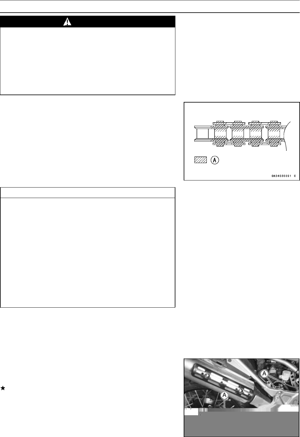
[A] Apply oil
CAUTION
The O-rings between the side plates seal in the lu-
bricant between the pin and the bushing. To avoid
damaging the O-rings and resultant loss of lubri-
cant, observe the following rules:
Use only kerosene or diesel oil for cleaning an O
-ring drive chain.
Any other cleaning solution such as gasoline
or trichloroethylene will cause deterioration and
swelling of the O-ring.
Blow the chain dry with compressed air immedi-
ately after cleaning.
Complete cleaning and drying the chain within 10
minutes.
•Apply oil to the sides of the rollers so that oil will penetrate
to the rollers and bushings. Apply the oil to the O-rings so
that the O-rings will be coated with oil.
•Wipe off any excess oil.
Brakes
Brake Fluid Leak (Brake Hose and Pipe) Inspection
•Apply the brake lever or pedal and inspect the brake fluid
leak from the brake hoses [A] and fittings.
If the brake fluid leaked from any position, inspect or re-
place the problem part.
2-28 PERIODIC MAINTENANCE
Maintenance Procedure
Brake Hose Damage and Installation Condition
Inspection
•Inspect the brake hose and fittings for deterioration,
cracks and signs of leakage.
○The high pressure inside the brake line can cause fluid to
leak [A] or the hose to burst if the line is not properly main-
tained. Bend and twist the rubber hose while examining
it.
Replace the hose if any cracks [B] or bulges [C] are no-
ticed.
Tighten any loose fittings and any banjo bolts.
Torque - Brake Hose Banjo Bolts: 34 N·m (3.5 kgf·m, 25
ft·lb)
•Inspect the brake hose routing.
If any brake hose routing is incorrect, route the brake hose
according to Cable, Wire and Hose Routing Section in the
Appendix chapter.
Brake Operation Inspection
•Inspect the operation of the front and rear brake by run-
ning the vehicle on the dry road.
If the brake operation is insufficiency, inspect the brake
system.
WARNING
When inspecting by running the vehicle, note a
surrounding traffic situation enough in the place of
safety.
Brake Fluid Level Inspection
•Check that the brake fluid level in the front/rear brake
reservoirs [A] is above the lower level line [B].
NOTE
○Hold the reservoirs horizontal by raising the motorcycle
perpendicular to the ground when checking brake fluid
level.
Special Tool - Jack: 57001-1238
•Remove the right side cover.
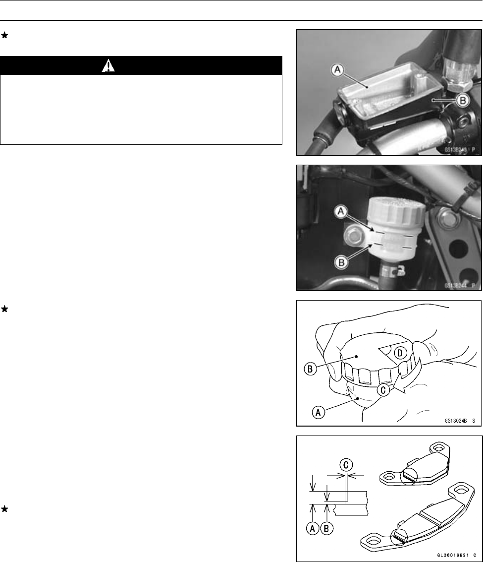
PERIODIC MAINTENANCE 2-29
Maintenance Procedure
If the fluid level is lower than the lower level line, fill the
reservoir to the upper level line [A] in the reservoir [B].
WARNING
Change the brake fluid in the brake line completely
if the brake fluid must be refilled but the type and
brand of the brake fluid that is already in the reser-
voir are unidentified. After changing the fluid, use
only the same type and brand of fluid thereafter.
Recommended Disc Brake Fluid
Grade: DOT4
If the rear brake reservoir cap is open to fill the brake fluid,
follow the procedure below to install the cap correctly.
○First, tighten the brake fluid reservoir cap [B] clockwise
[C] by hand until the resistance is felt fully; then, tighten
the cap an additional 1/6 turn [D] while holding the brake
fluid reservoir [A] body.
Brake Pad Wear Inspection
In accordance with the Periodic Maintenance Chart, in-
spect the brake pads for wear.
•Remove the pads.
•Check the lining thickness [A] of the pads in the caliper.
If the lining thickness of either pad is less than the service
limit [B], replace both pads in the caliper as a set.
Stepped Portion [C]
Pad Lining Thickness
Standard: 5.15 mm (0.203 in.)
Service Limit: 1 mm (0.04 in.)
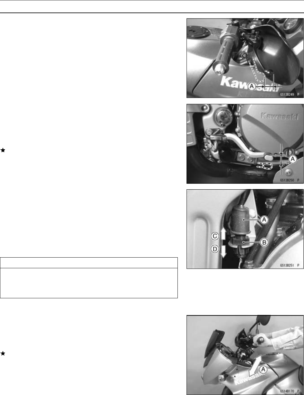
2-30 PERIODIC MAINTENANCE
Maintenance Procedure
Brake Light Switch Operation Inspection
Front Brake Light Timing Inspection
•Turn on the ignition switch.
•The brake light should go on when the brake lever is ap-
plied or after the tip of brake lever moves about 10 mm
(0.39 in.) [A].
Rear Brake Light Timing Inspection
•Turn on the ignition switch.
•Check the operation of the rear brake light switch by de-
pressing the brake pedal. The brake light should go on
as specified.
If it does not, adjust the brake light timing.
Brake Light Timing
Standard: On after about 15 mm (0.59 in.) pedal
travel [A]
Rear Brake Light Timing Adjustment
Brake light timing is adjusted by changing the position of
the rear brake light switch [A].
•Adjust the position of the switch so that the brake light
goes on after the specified pedal travel by turning the ad-
justing nut [B].
[C] Lights sooner.
[D] Lights later.
CAUTION
To avoid damaging the electrical connections in-
side the switch, be sure that the switch body does
not turn during adjustment.
Suspension
Front Forks/Rear Shock Absorber Operation
Inspection
•Pump the forks down and up [A] 4 or 5 times, and inspect
the smooth stroke.
If the forks do not smoothly or noise is found, inspect the
fork oil level or fork clamps (see Front Fork Oil Change in
the Suspension chapter).
