Kawasaki Vulcan 1700 Voyager Users Manual
VULCAN 1700 VOYAGER to the manual e319ef11-e558-4727-ad52-b963d1e2d182
2015-01-26
: Kawasaki Kawasaki-Vulcan-1700-Voyager-Users-Manual-219724 kawasaki-vulcan-1700-voyager-users-manual-219724 kawasaki pdf
Open the PDF directly: View PDF ![]() .
.
Page Count: 6
Installation Instructions
Assembly Instructions
Description: CB Radio Kit Model: Vulcan 1700 Voyager
Part Number: K10400-037 Approximate
Assembly Time:
60 min.
Installation of this accessory should be performed by a qualied technician with the proper tools and
equipment.
If you are in doubt as to any part of the installation, please ask your authorized Kawasaki dealer to
complete the installation. Please note that Kawasaki cannot assume any responsibility for damage
resulting from incorrect installation.
Parts List Tools Required:
Seq. Description Qty Tool Description
1. CB Radio Module Assembly 1 Drill Motor
Scribe
1/16” Drill Bit
7mm (1/4”) Drill Bit
5mm Hex Head Driver
Socket Driver
10mm Socket
Philips Head Screwdriver
2. M6 x 30mm Bolts 2
3. CB Antenna Cable 1
4. CB Antenna Base 1
5. M6 x 20mm Philips Head Bolt 1
6. CB Ground Strap 1
7. M6 Lock Nuts 2
8. Lock Washer 1
9. Belleville Washer 1
10. M6 Cap Nut 1
11. Cable Ties, 6 inch 8
12. Cable Tie, 14.5 inch 1
13. CB Antenna Mast 1
14. Star Washer 1
Installation Preparation
Parts Removal
zSet bike securely on side stand on level ground. Switch off
ignition and remove key.
zRefer to the VN1700 Voyager Service Manual and remove the
fairing. Remove the front and rear seats, fairing and left fairing
lower cover (black piece).
zOpen the trunk and remove the tray by pressing the center of
the four lock rivets.
zRemove the fuel tank mounting bolts and lift the tank to expose
the frame.
Installation
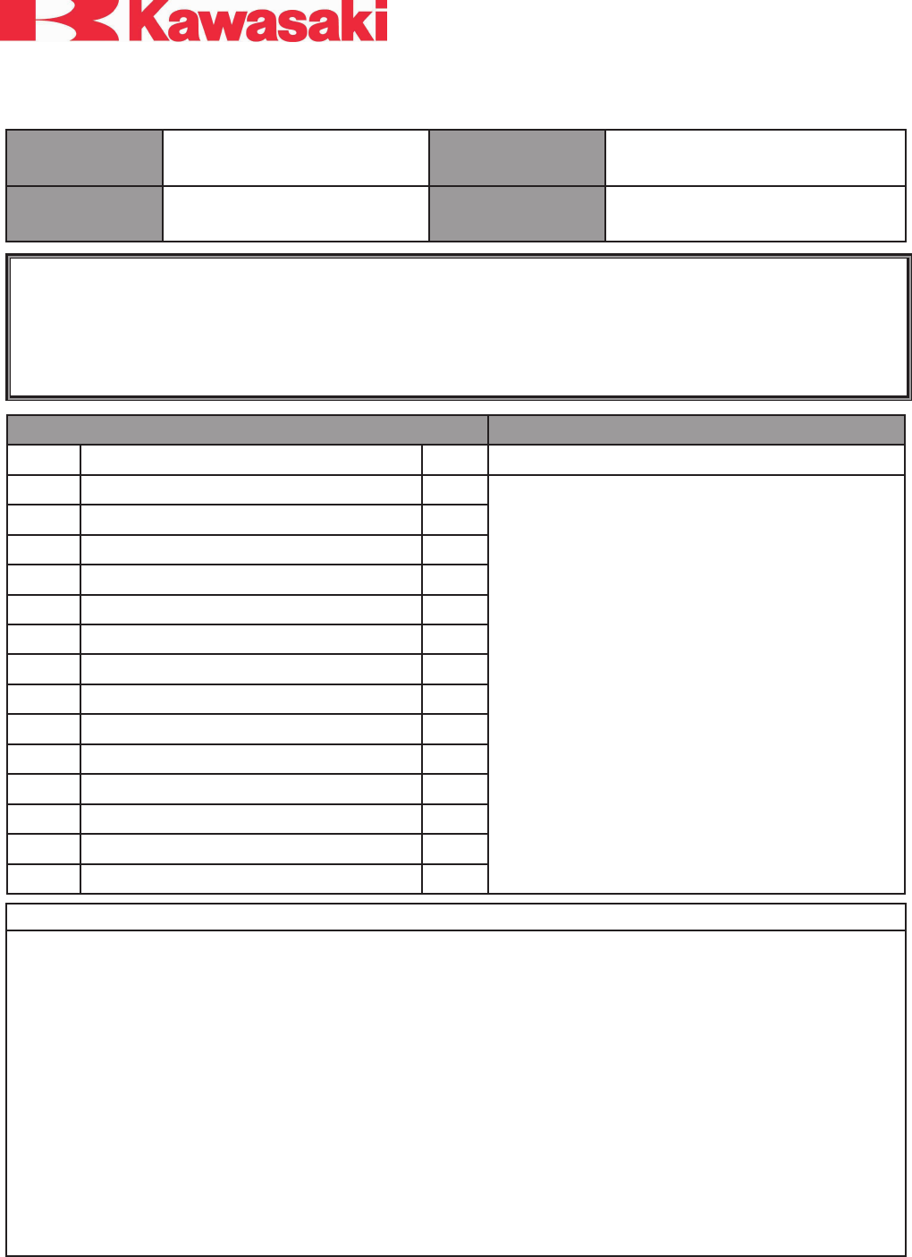
Install CB Module
zMount the CB module using the two supplied 6 x 30mm bolts
on the top and re-using the lower bolt. Tighten all three bolts
rmly but do not over tighten as this may damage the plastic
fairing lower.
zRoute the harness from the CB module behind the left engine
guard and into the left side of the fairing. Find the matching
multi-pin connector at the left side of the radio and connect to
the CB module harness. Press the connectors together rmly
to engage the waterproof seals. Secure the cables as needed
with provided cable ties.
NOTE
oIf the optional XM Radio K10400-038 will also be installed,
a K10400-042 Splitter Cable (sold separately) will also be
needed to connect both XM and CB to the OE radio.
Install CB Antenna
zConnect the threaded end of the CB antenna cable to the right-
angle tting on the CB module and rmly hand tighten.
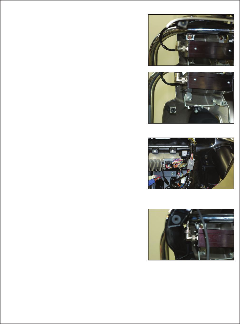
zRoute the other end of the antenna cable along the chassis
and under the center of fuel tank. Follow the routing of the AM/
FM antenna cable to the rear and into the trunk. Continue to
route the CB antenna cable along the left and rear of the trunk
to the right rear corner. Secure the cable with wire ties.
zCut the antenna base drilling template out of the instruction
sheet. Carefully fold it at the score lines and tape to the inside
right rear corner of the trunk as shown.
zCarefully mark the center of the holes with a scribe and drill
pilot holes from the inside of the trunk using a 1/16” bit. Finish
drilling the holes from the outside using a 7mm (1/4”) bit.
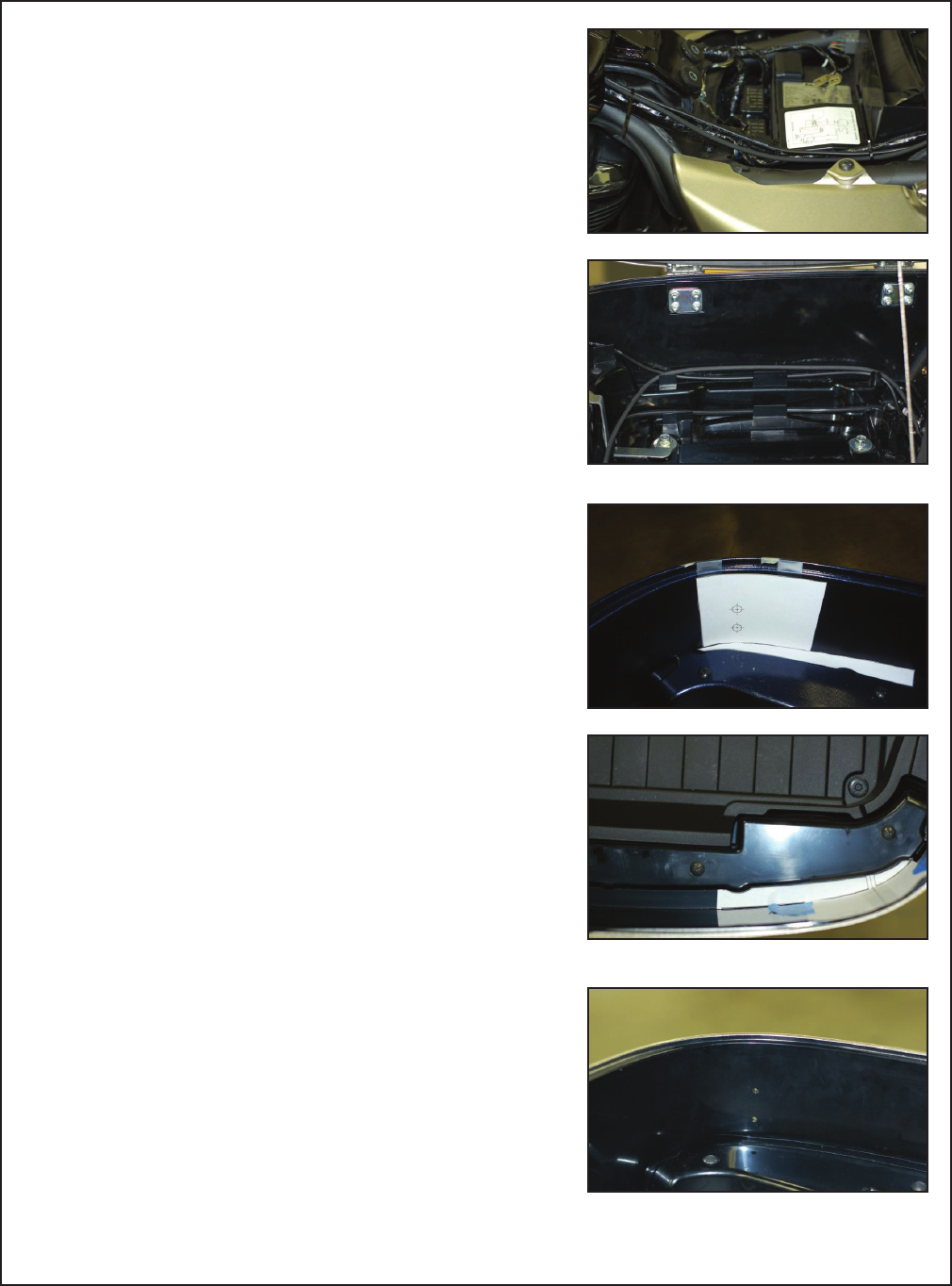
zInstall the antenna base from the outside of the trunk. Install
Belleville (curved) washer and locknut onto the threaded brass
post. Do not over-tighten as this may damage the plastic base.
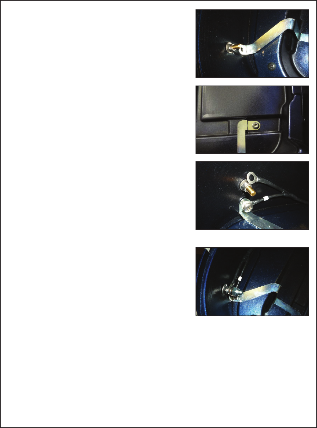
zRemove the right rear trunk bolt and install the provided metal
grounding bracket at this point and to the lower mounting hole
of the antenna base.
zConnect the black wire with white marking tape from the CB
antenna cable to the lower threaded hole in the antenna base
with the provided Philips head screw.
zInstall remaining ring terminal from the antenna cable onto the
brass post and lock down with lock washer and cap nut.
zInstall the antenna mast with star washer and conrm the
vertical positioning of the mast matches that of the AM/
FM antenna. Adjust the positioning of the AM/FM antenna
accordingly. Tighten the mast securely but do not over tighten.
NOTE
oDo not use thread locking compound on the threads of the
antenna mast as this may damage the plastic.
zSwitch the ignition to “accessory” and turn the radio on, then
follow the Owners Manual to select the “CB on” function. The
CB channel in the lower left corner of the radio display should
show the CB channel number. If the channel number does
not show, check all connections and the accessory fuse. After
proper CB operation is conrmed, switch off the ignition.

Please check/adjust all fasteners in regular intervals.
© Kawasaki Motors Corp., U.S.A., August 2009
zAfter conrming proper operation of the CB radio, reinstall the
fairing, left fairing lower, lower cover, front and rear seats, and
tank. Check carefully to be sure that the wires are not caught
or pinched. Install the trunk tray with the four press rivets and
close and lock the trunk lid.
NOTE
oWipe the CB antenna clean with a soft damp cloth. Do not use
any harsh abrasive cleaners. The CB module and connectors
are water resistant for normal inclement riding conditions only.
Do not direct water at any component.
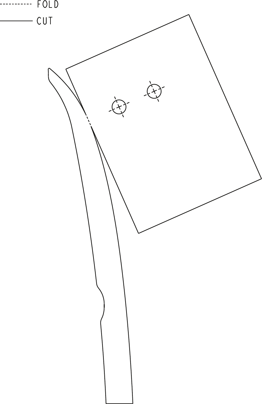
Antenna Base Drilling Template
