Keeson Technology RF359A Remote Control User Manual
Jiaxing Shufude Electric Bed Co., Ltd. Remote Control Users Manual
Users Manual
OKIN Refined Electric Technology Co., Ltd
Page 1 of 7
Operating Manual of Remote Control system
1、 Interface of the remote control
2、Button description
A. HEAD UP button:Press and hold the button, the Head actuator will go up. Stop
when released.
B. HEAD DN button:Press and hold the button, the Head actuator will go down.
Stop when released.
C. FOOT UP button:Press and hold the button, the Foot actuator will go up. Stop
when released.
OKIN Refined Electric Technology Co.,Ltd
Page 2 of 7
D. FOOT DN button:Press and hold the button, the Foot actuator will go down.
Stop when released.
E. ZERO GRAVITY button: Click the button, the Head and Foot actuator will start
up and keep running until arriving to the zero gravity position. Running can be stopped by
clicking any button.
F. FLAT button: Click the button, the Head and Foot actuator will start up and
keep running until arriving to the FLAT position. Running can be stopped by clicking any
button.
G. MEMORY 1 button: Click the button, the Head and Foot actuator will start up
and keep running until arriving to the Memory 1 position preset by user. Running can be
stopped by clicking any button.
H. MEMORY 2 button: Click the button, the Head and Foot actuator will start up
and keep running until arriving to the Memory 2 position preset by user. Running can be
stopped by clicking any button.
The blue LEDs for backlight are on as long as any button is pressed. IF all buttons are
released the LEDs will automatically turn off three seconds later.
The blue LED for power is always on as long as the power on.
The below positions can be changed or set by the end user.
The Zero gravity position;
The Memory 1 position;
The Memory 2 position;
The procedure to set these special positions is below:
OKIN Refined Electric Technology Co.,Ltd
Page 3 of 7
Step 1: Click the button to flat the bed;
Step 2: Adjust the Head and Foot position to a desired position by pressing the
button HEAD_ UP or HEAD_DOWN or FOOT_UP or FOOT_DOWN;
Step 3: Press and hold the button for 3sec, backlight LED start flashing;
Step 4: Release the button then click one of or or
button before LED stop flashing. Then the Flashing stops immediately to
indicate the corresponding operating has completed successfully.
ALL of the Zero gravity position and the Memory 1 position and the Memory 2
position can be restored to default sets by pressing and holding the
button for approximate six seconds until the backlight LEDs finally stop flashing
from first flashing.
I. Massage Mode button:
Click the button the vibrating mode will change by one level, total 4 levels.
When it has been level 4, it will return to level 1 if click the button.
J. Head Massage INTENSITY ICREASEMENT and DECREASEMENT button:
Click the button the Head vibrating intensity will raise up one level, total 4 levels.
OKIN Refined Electric Technology Co.,Ltd
Page 4 of 7
K. Foot Massage INTENSITY ICREASEMENT and DECREASEMENT button:
Click the button the Foot vibrating intensity will raise up one level, total 4 levels.
The number of level represents the vibrating intensity. More big number of the level,
more strongly vibrating it is. The strongest vibrating is level 3, and the weakest is level 0.
Implement adjustment of the vibrating intensity is the way known as “PWM”. Different
duty cycle of PWM makes different intensity. The value of the duty cycle corresponding to
the level is below:
Duty cycle Level
0% 0
20% 1
35% 2
50% 3
L. Massage time button:
Press the button and released to stop all moves (including the actuators and vibrator)
and change circularly the vibrating time of the vibrator by one level once, total 3 levels。
The time means that vibrating keeps on for this period then automatically stops if no any
button related to vibrating is pressed again. The time and the LED indication are below:
This LED flash a time, the vibrating time is 10minutes;
This LED flash a time, the vibrating time is 20minutes;
This LED flash a time, the vibrating time is 30minutes;
10min,20min,30min LED
3、Wireless pairing operation (Remote control code)
Step1: Power on the control box. (Put electricity on the control box.)
Step2: Double click on the light touch switch for pairing on the control box. At this time, the
pairing instructions LED on the control box light, and the control box is in a condition of pairing
OKIN Refined Electric Technology Co.,Ltd
Page 5 of 7
Step3: Hold the silicone button in the batter cover on the back of the remote control device,
when the LED in the silicone button flashes, it indicates that the remote control is searching for
the repaired control box. When the LED of matching button within the remote control has a long
light and the LED on the paired control box is off at the same time, the pairing operation is
finished. To test the pairing is successful or not as well as the head up / down, feet up/ down
buttons and other buttons related to the actuator, if you can hear the ticking sound that
released by the relay, it indicates that the repairing is successful. Otherwise, repeat all the steps
above.
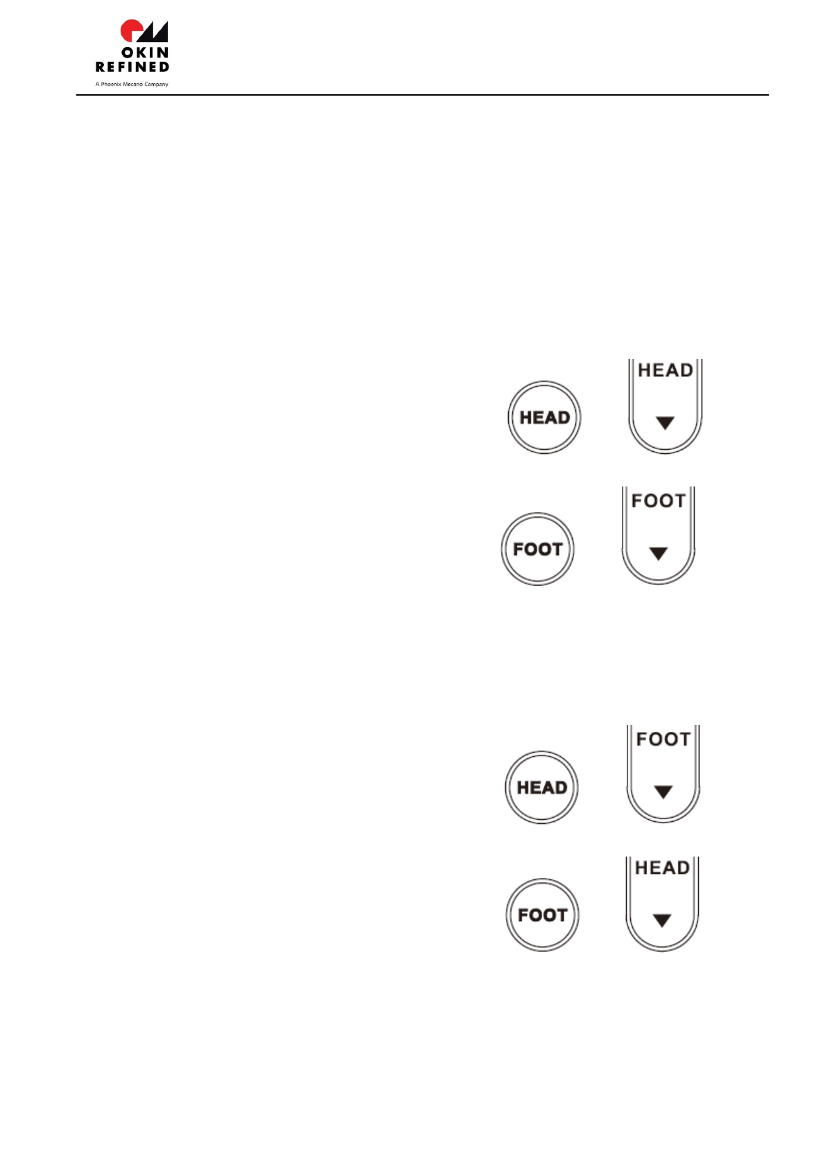
4、Lock and unlock
Press and keep 2 seconds simultaneously both buttons and until the
LEDs flash, the remote control will be locked.
Press and keep 2 seconds simultaneously both buttons and until the
LEDs flash, the remote control will be unlocked.
If nothing is done for 5 minutes on it and the function being locked automatically is enabled, the
remote control will be locked automatically.
The function being locked automatically can be enabled or disabled.
Press and keep 2 seconds simultaneously both buttons and until the
LEDs flash, the function being locked automatically will be enabled.
Press and keep 2 seconds simultaneously both buttons and until the
LEDs flash, the function being locked automatically will be disabled.
In the locked status the actuators will not be operated. But the vibrator be still able to be
operated.
OKIN Refined Electric Technology Co.,Ltd
Page 6 of 7
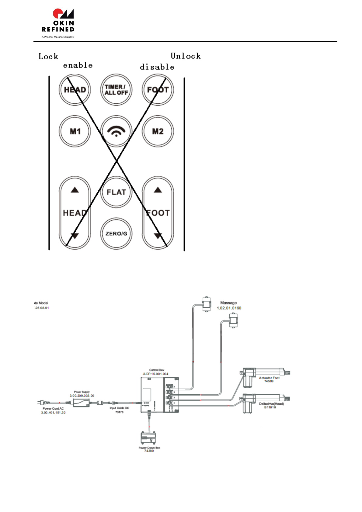
5、Connect to the Control Box

OKIN Refined Electric Technology Co.,Ltd
Page 7 of 7
The control box is designed for using the SMPS of 29VDC/ around 2A as the power. It is
necessary to use the SMPS provided by us when normal operation.
In the case of the AC power utility failure, the batteries for backup of 18VDC can be used as
the power. It is only for flatting the bed plate without load if the batteries used as the power
and each one of the batteries must be new with 9V voltage. You can press and hold the
emergency button on the body of the control box to flat the bed. The movement sequence
is that the Head and Foot actuator goes down until arrives to the limit. If release the button,
all movement will stop immediately.It isn’t also strongly recommended to start the massage
motors when the battery box used as power.
Any Changes or modifications not expressly approved by the party responsible for compliance
could void the user’s authority to operate the equipment.
This device complies with part 15 of the FCC Rules. Operation is subject to the following two
conditions: (1) This device may not cause harmful interference, and (2) this device must
accept any interference received, including interference that may cause undesired operation.