Kelvin Hughes CTX-A8 'X' Band Radar User Manual Installation Guide
Kelvin Hughes Limited 'X' Band Radar Installation Guide
Installation Guide

INSTALLATION OF UPMAST X-BAND TRANSCEIVER CAE-A12-20 (25kW)
GENERAL
8The Upmast Transceiver comprises a casting with two cover plates. Both cover
plates are secured by four bolts and may be removed to access the motor and
transceiver PCBs mounted within. The PCBs are secured to mounting plates which
form a safety cage whilst in the closed position.
FITTING
9The Upmast Transceiver should be installed in such a position to avoid any RF
interference and where Blind Arcs, caused by obstructions, e.g. masts, funnels,
etc, are eliminated or minimised. Funnels, crosstrees and other large obstructions can
also reflect energy and give rise to spurious echo returns, especially in close proximity to
land.
10 The Upmast Transceiver must not be mounted where the temperature exceeds
70oC.
11 The Upmast Transceiver must be kept clear of ship’s flexible communication
antennas to avoid damage to both.
12 The Upmast Transceiver must be mounted more than 914mm above any flat
surface, when the flat surface is greater than the diameter swept by the antenna.
13 The Upmast Transceiver must not be positioned in the close proximity of any
magnetic compass or D/F antenna, etc.
NOTE A heavy duty earthing strap or cable must be taken from the upmast
transceiver/turning mechanism to the ship’s earth.
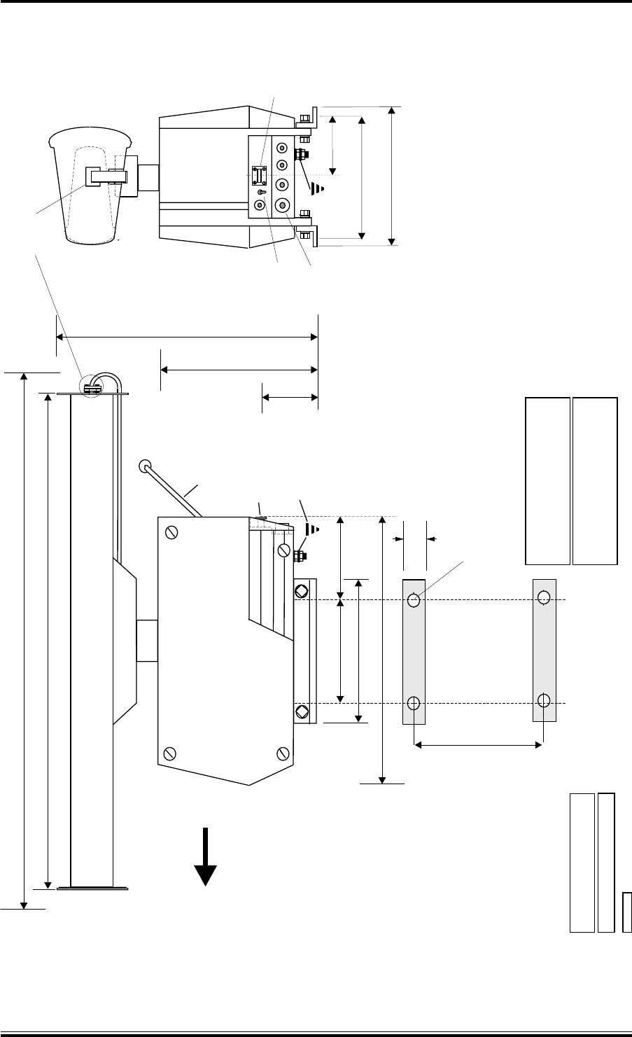
14 Position the Upmast Transceiver at the installation site, supporting the unit
where necessary, and mark out the mounting holes for drilling. Refer to Figure 1
for dimensions.
15 Allow sufficient cable length, (approximately 1m) on all cables to enable them to
be routed through the Transceiver unit. Refer to Figures 2 and 4 for details.
Ensure that there is sufficient slack on all cables to allow for full movement of the
equipment on its mounts during any sudden shock, or extreme movement of the vessel.
WARNING
THE UNIT MUST NOT BE LIFTED BY MEANS OF THE
ANTENNA OR WING CASTING. THE LIFTING SUPPORTS
MUST GO UNDER THE CASTING.
Issue 1 4 mkiv
KH1254
Chapter 2
mkiv 5 Issue 1
KH1254
Chapter 2
All dimensions in millimetres.
Turning Mech Weight : 30kg
Antenna (2.4m) Weight : 21kg
oo
o
Power Consumption : 150VA
Operating Temperature: -25 C to +55 C
Relative Humidity 95% : +40 C
OPERATING TEMPERATURE RANGE
COMPASS SAFE DISTANCES :-
Standard Compass 3m (Grade I)
Steering Compass 1.8m (Grade II)
KELVIN HUGHES
OFF
ON
FWD
ARM
In transit MonitorArm is stowed inside
Turning Mechanism carton
PTFE WINDOW FITTED AT THIS CONNECTION
EARTHING POINT
(TORQUE LOADED TO 75 kg/m)
CABLE
GLANDS
WAVEGUIDE
OUTLET
SAFETY
SWITCH
OUTER HOUSING
14 mm holes (4 0 ff )
MONITOR
M12 bolts
1-2MM LESS THAN
WAVEGUIDE FLANGE
40
TURNING RADIUS 2412 or 1990
2262 or 1840
645
406
140
250
570
310
150
270
270
310
135
CD-4541
Figure 1 - Upmast X-Band Transceiver CAE-A12-20 (25kW):
Installation Dimensions
Issue 1 6 mkiv
KH1254
Chapter 2
TB1C TB1B TB1A TB
2
MODULATOR
CONTROL
PCB
HEADING
LINE PCB
FWD
EARTHING POINT
ON UNDERSIDE
POWER
SUPPLY
UNIT
VIDEO & SYNC
TERMINAL
PLATE
MAINS FILTER SHIP'S MAINS
SAFETY SWITCH
DISPLAY (38 CORE CABLE CODE M)
TX MONITOR ARM
CD-4542
PLB
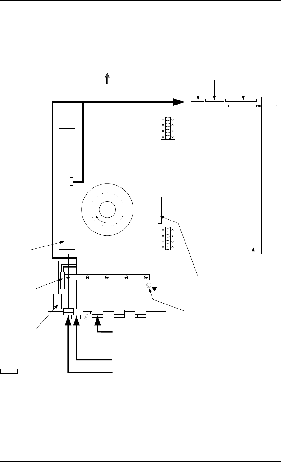
Figure 2 - X-Band Upmast Transceiver: Cable Routing
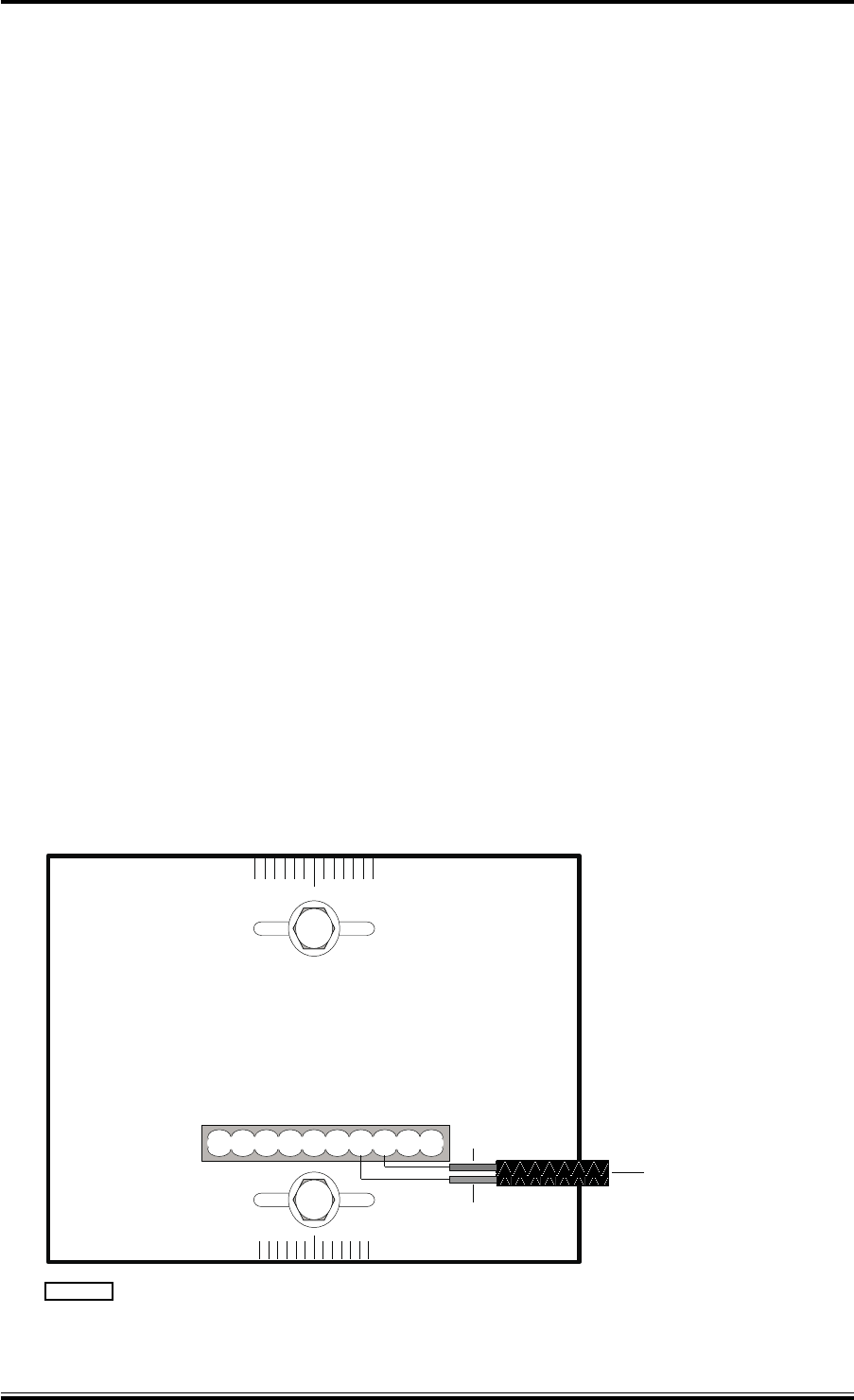
MONITOR ARM
16 The Monitor Arm is positioned by means of a channel above the glands at the
rear of the casting, and is secured by a clamp with two retaining screws. The
neon points to starboard when viewed from the rear of the transceiver.
17 The cable is routed through the gland nearest the channel and connects to PLA-7
(red) and PLA-8 (blue) on the Azimuth PCB (CTX-A106). Refer to Figure 3.
ELECTRICAL CONNECTION
18 For detailed electrical connection of cables to the transceiver unit, refer to the
installation diagrams in Figure 5. Figure 7 shows a typical arrangement with the
MkIV transceiver connected to the NUCLEUS 3 Display, via the Radar Interface Unit
(RIU). Ensure that all cables are secured to their associated entry point and that
screened cables are earthed to their respective units.
19 Connecting cables between the display and the transceiver should be limited to a
length of 65 metres. Where the distance between transceiver and display
exceeds 65 metres, special low loss co-axial cable should be used. Where the distance
between transceiver and display exceeds 180 metres, special low loss co-axial cable,
and line amplifiers for video and sync must be fitted (see Annex A).
20 Cable specifications are detailed in Paragraphs 24 onwards.
CHECKS AFTER FITTING
21 Setting to work instructions are described in Chapter 3, Commissioning. The
transceiver must be thoroughly checked for security, accessibility, and correct
cabling runs.
mkiv 7 Issue 1
KH1254
Chapter 2
TO TX MONITOR ARM
CAE-A106
RED
PLA
BLUE
6
12345678910
CD-1134
Figure 3 - X-Band Upmast Transceiver Transmitter Monitor Arm:
Connection Diagram