Kelvin Hughes DTX-A3 RADAR User Manual KH1264 issue 1 vp
Kelvin Hughes Limited RADAR KH1264 issue 1 vp
Users Manual

SHIP'S TECHNICAL MAN UAL
INSTALLATION, COMMISSIONING
and
MAINTENANCE INFORMATION
for
SharpEyeTM X-BAND UPMAST TRANSCEIVER
fitted with ANTENNA LPA-A25
PUB LI CA TION KH1264
Is sue 2
July 2009
Kel vin Hughes Lim ited
New North Road, Hainault, Il ford, Essex IG6 2UR, UK
Tele phone: +44 20 8502 6887
Fac sim ile: +44 20 8559 8526
Telex: 896401
www.kelvinhughes.com
Registered Office: New North Road, Hainault, Ilford, Essex IG6 2UR
Incorporated in England No. 1030135
VAT No: GB 918080917/000
COPYRIGHT
ã Copyright Kelvin Hughes Ltd. 2009
All rights reserved. No part of this publication may be
reproduced, transmitted, transcribed, translated or stored
in any form or by any means, without the written
permission of Kelvin Hughes Limited.
Technical details contained in this publication are subject to
change without notice.
Page ii Is sue 2

AMEND MENT RE CORD
When an amendment is incorporated into this publication, the details should be recorded
below. Where the equipment has been modified, the modification number shown on the
Amendment Instruction Sheet is also to be recorded.
Amdt. No. Date Inserted Initials Mod. No.
Is sue 2 Page iii
THIS PAGE INTENTIONALLY BLANK
Page iv Is sue 2
CONTENTS
PRE LIM I NARY PAGES
Title Page
Amendment Record Page iii
Contents (this page) v
Foreword vii
Health and Safety Notice Page ix
Emergency Resuscitation xi
Electrostatic Caution Page xii
Code of Safe Working Practices CP 225
Equipment Registration Certificate
CHAP TERS
Chapter 1 - General Description
Chapter 2 - Specification
Chapter 3 - Technical Description
Chapter 4 - Installation
Chapter 5 - Commissioning
Chapter 6 - Maintenance
Chapter 7 - Parts List
Installation and Service Reports
Is sue 2 Page v
THIS PAGE INTENTIONALLY BLANK
Page vi Is sue 2
FOREWORD
This Ship's Manual provides installation, commissioning and maintenance information for the
SharpEyeTM X-band Transceiver and Antenna.
Maintenance must only be undertaken by qualified service engineers or by Kelvin
Hughes and their approved agents. Unauthorised repair of equipment during the
Warranty period will invalidate the Warranty. If you wish to undertake the
maintenance of the equipment, then you need to ensure that the service engineers have
undertaken a training course approved by Kelvin Hughes.
A general description of the equipment and the specification is given in Chapters 1 and 2
respectively. A full technical description to unit level is given in Chapter 3, including block
diagrams and interconnection diagrams.
The Installation Information in Chapter 4 includes all physical installation information,
including coaxial cable installation, and generic cabling data. For detailed cabling
information to the display, refer to your System Manual.
The Commissioning Information in Chapter 5 includes generic information on
commissioning from the master display and information specific to this equipment. For
detailed information on commissioning from the display, refer to your System Manual.
The Maintenance Information in Chapter 6 covers routine maintenance procedures and fault
diagnosis and repair to unit level.
A Parts List to unit level is given in Chapter 7.
A section is provided at the end of the manual for inclusion of customer information relating
to the specific equipment supplied to your ship, including installation and service reports, and
software information.
When operating, installing or maintaining your system, this manual should be used in
conjunction with the following:
System Manuals provided for the particular installation, which provide Operating
Installation and System Commissioning Information
Manuals for the other equipment supplied as part of the System.
Refer overleaf for contact details for the Kelvin Hughes Customer Service Group.
Is sue 2 Page vii
If a unit exhibits a fault, and you are unable to fix it, and therefore require a service engineer
to attend your vessel, please contact our Service Control Centre, giving full details of the
following:
1. Name of vessel (Phone or Fax number if fitted)
2. Equipment type
3. Software status (version number) (if applicable)
4. Next port of call, ETA/ETD and ship's agents
5. Fault description (with as much detail as possible)
6. Purchase order number with invoicing details
7. Contact Name
You may contact our direct line, send a fax or send an email.
Kelvin Hughes, Customer Services Group, New North Road, Hainault, Essex IG6 2UR
(UK)
Phone: Main UK Switchboard: 44 (0)20 8502 6887
Direct Service Line & Out of Hours Emergency Technical Support: 44 (0)20 498 1761
email: service@kelvin hughes.co.uk
If you have any technical queries or require any technical information regarding your Kelvin
Hughes bridge equipment you may phone our direct Service Line. You may also contact our
direct line, send or fax an email to:
technical.advice@kelvinhughes.co.uk
If you require information on our training facilities or would like to have a quote for training,
please give as much detail as possible. You may contact our direct line, send a fax or send an
email to:
training@kelvinhughes.co.uk
For quotation of spares, or if you require any information regarding availability, lead times
etc, you may contact our direct line, send a fax or send an email to:
spares@kelvinhughes.co.uk
Please Note. All quote requests must have full contact details. Our preferred method of
contact is email, but Fax or Post may be used. We normally supply the quotation by email.
For more information regarding our contract services or to arrange a meeting with a member
of our team you may email us at the following address. Those customers already holding an
agreement with us may also use this email address to request a service, providing the same
information as mentioned for service (no purchase order number required). You may contact
our direct line, send a fax or send an email to:
contract.support@kelvinhughes.co.uk
Page viii Is sue 2
IMPORTANT NOTICES
HEALTH AND SAFETY
1All personnel are required to study these notices and familiarise themselves with all
applicable safety precautions and bring them to the attention of others in the vicinity.
HIGH VOLT AGE WARNING
LETHAL HIGH VOLTAGES ARE PRESENT IN THE TRANSCEIVER
2A current of 100 mA passing through the human body for one second can kill. This can
occur at voltages as low as 35 V AC or 50 V DC. Some equipment in the system uses
electrical power that can be lethal. Whenever practical, before carrying out installation,
maintenance or repair, personnel involved must:
(1) Isolate the equipment from the electrical supply.
(2) Make tests to verify that the isolation is complete.
(3) Ensure that power cannot be accidentally reconnected.
DO NOT OPEN ANY OF THE UNITS WHEN THE RADAR IS OPERATIONAL -
UNLESS FULLY QUALIFIED TO DO SO.
3If it is essential to work on the equipment with power connected, work must only be
undertaken by qualified personnel who are fully aware of the danger involved and who
have taken adequate safety precautions to avoid contact with dangerous voltages.
HEALTH HAZ ARD
4This equipment contains materials which produce toxic fumes when ignited.
5The inhalation of dust and fumes or any contact with lubricants when cleaning the
equipment may be temporarily harmful to health, depending on individual allergic
reactions. Components which are broken or overheated may release toxic fumes or dust and
must be treated with caution. Do not inhale the fumes and ensure that the dust and debris do not
enter open cuts or abrasions. It is prudent to regard all damaged components as being potentially
toxic, requiring careful handling and appropriate disposal.
Is sue 2 Page ix
CD-0844
CD-0845

RA DI A TION HAZ ARD: NON-ION ISING
AERIAL RADIATION HAZARD: INJURY CAN RESULT FROM EXPOSURE TO
THE MAIN BEAM OF A STATIONARY RADAR AERIAL. DO NOT STAND
LESS THAN 2 m FROM THE CENTRAL FRONT FACE OF THE AERIAL.
6It is accepted in most countries that no significant hazard is presented by radio frequency
mean power density levels up to 10mW/cm. RF power levels in excess of this may cause
harmful effects, particularly to the eyes.
7 Users of cardiac pacemakers should be aware that radio frequency transmissions, can
damage some such devices or cause irregularities in their operation. Persons using a
pacemaker should ascertain whether their device is likely to be affected before exposing
themselves to the risk of malfunction.
SAFETY ALOFT
AERIAL ROTATION: BEFORE MAINTENANCE TO THE TURNING
MECHANISM TAKES PLACE, DISABLE AERIAL ROTATION.
8When working aloft, ensure that it is brought to the attention of someone in authority at
deck or at ground level and that suitably placed warning notices are posted warning that
work aloft is in progress. Ensure that the means of access aloft is secure and beware of wet or
slippery ladder rungs and working areas.
9When working on or near a radar scanner and other moving or r.f. radiating equipment,
ensure that it is switched off and that the fuses have been removed and retained.
PER SONAL PRO TEC TION
10 Personal protection must be used whenever the possibility of an uncontrolled hazard
exists. For example, a suitable face visor, gloves and a body apron should be worn when
handling cathode ray tubes, as a precaution against injury in the event of breakage.
EQUIP MENT SAFETY
11 Do not run the radar with the rotating joint output disconnected.
12 Removal of printed circuit boards with power connected can damage FETs and
Integrated Circuits.
13 The circuitry used on the equipment PCBs utilises CMOS Integrated Circuits. All the
relevant CMOS precautions must be taken to avoid damage to CMOS circuitry when any
board is removed.
14 The equipment should be serviced by qualified agents only.
Page xIs sue 2

Is sue 2 Page xi
ELECTRIC SHOCK RESUSCITATION
1SHOUT FOR HELP.
SWITCH OFF ELECTRICITY IF POSSIBLE.
REMOVE CASUALTY FROM DANGER.
REMOVE ANY OBVIOUS OBSTRUCTION TO BREATHING.
SWITCH OFF ELECTRICITY IMMEDIATELY. IF NOT POSSIBLE, DON'T WASTE TIME SEARCHING FOR A SWITCH
SAFEGUARD YOURSELF WHEN REMOVING CASUALTY FROM HAZARD.
IF CASUALTY IS STILL IN CONTACT WITH ELECTRICITY AND THE SUPPLY CANNOT BE ISOLATED, STAND ON A DRY
NON-CONDUCTING MATERIAL (RUBBER MAT, WOOD, LINOLEUM). USE RUBBER GLOVES, DRY CLOTHING WOODEN BROOM,
STOOL, CHAIR, LENGTH OF DRY ROPE OR WOOD TO PULL OR PUSH CASUALTY AWAY FROM THE HAZARD.
IF CASUALTY IS NOT BREATHING, START RESUSCITATION AT ONCE.
GET HELP.
MEDICAL ASSISTANCE MAY BE OBTAINED ON / AT ...............................................
2
3
SHOUT & SHAKE CASUALTY (FOR RESPONSE)
LOOSEN NECKWARE,
TILT HEAD BACKWARDS & PUSH CHIN UPWARDS
PERFORM CPR:
HEEL OF HAND IN CENTRE OF BREASTBONE
WITH OTHER HAND ON TOP (FINGERS OFF CHEST)
WRISTS & ELBOWS LOCKED COMPRESS DOWN 5cm.
REPEAT 30 TIMES IN TOTAL (SPEED 100 PER MINUTE)
HEART HAS STOPPED BEATING, LAY CASUALTY
ON THEIR BACK ON FIRM SURFACE eg. FLOOR
SIGNS OF LIFE/CIRCULATION PRESENT
CHECK FOR SIGNS OF CIRCULATION,
SIGNS OF LIFE (< 10 SECONDS).
WHEN NORMAL BREATHING COMMENCES,
PLACE CASUALTY IN RECOVERY POSITION
KEEP CASUALTY AT REST.
MOVE USING A STRETCHER.
WATCH CLOSELY, PARTICULARLY FOR DIFFICULTY
IN BREATHING. LIGHTLY COVER WITH BLANKETS
OR OTHER MATERIALS
SIGNS OF LIFE/CIRCULATION ABSENT
CD-1265 ISSUE 2
CONTINUE CPR WITH 30 CHEST COMPRESSIONS,
THEN 2 BREATHS UNTIL CASUALTY REVIVES &
COLOUR IMPROVES, OR HELP ARRIVES
OR YOU ARE EXHAUSTED.
OPEN AIRWAY, PINCH THE NOSE & HOLD THE CHIN.
TAKE NORMAL BREATH, SEAL MOUTH,
BLOW STEADILY (WATCHING CHEST RISE).
REMOVE MOUTH, CHECK THAT CHEST FALLS,
REPEAT RESCUE BREATH.
Page xii Is sue 2
ATTENTION
OBSERVE PRECAUTIONS
FOR HANDLING
ELECTROSTATIC SENSITIVE
DEVICES
CAUTION
Handling of Electrostatic-Sensitive Semiconductor Devices
Certain semiconductor devices used in the equipment are liable to damage due to static
voltage. Observe the following precautions when handling these devices in their
unterminated state, or sub-units containing these devices:
(1) Persons removing sub-units from an equipment using these devices must
be earthed by a wrist strap and a resistor at the point provided on the equipment.
(2) Soldering irons used during the repair operations must be low voltage types
with earthed tips and isolated from the mains voltage by a double insulated
transformer.
(3) Outer clothing worn must be unable to generate static charges.
(4) Printed Circuit Boards (PCBs) fitted with these devices must be stored and
transported in anti-static bags.
CD-1100

CP 225
Original May 03 1
CODE OF SAFE WORKING PRACTICES
FOR THE INSTALLATION AND COMMISSIONING
OF KELVIN HUGHES LIMITED MANUFACTURED EQUIPMENT
This code must be followed when installing or commissioning any
Kelvin Hughes Limited product.
Failure to follow this code invalidates the equipment warranty.
SAFETY
Reference must be made to the Safety Warnings located at the beginning of each
Kelvin Hughes Limited Manual and must be read and understood. These include but
are not limited to, the knowledge and understanding of: ‘Electric Shock
Resuscitation’, the safety interlock system, all lethal voltages present, source of
supply to all equipment, any hazardous material in the equipment or area of work,
radiation hazard from the beam of a Radar Antenna and any antenna rotation hazard.
Before working on antennas the following conditions must be met:
• A responsible person (such as the officer of the watch) must be informed that
there will be an engineer working on the system.
• The system interlock must be activated.
• The source of power to the system must be isolated.
• Warning notices must be posted at the system power source and at all displays
showing ‘MAN WORKING ALOFT DO NOT SWITCH ON’. Local language
considerations must be taken into account and included with the English statement
above.
• When working above a height of 1.5 metres safety harnesses must be worn and
must be clipped in to the superstructure.
• All tools must be securely lashed to ensure that they can not present a drop hazard.

CP 225
Original May 03 2
INSPECTION
Before commencing work, the proposed installation locations must be inspected and
accepted as being suitable for the equipment to be mounted securely following the
installation procedures which can be found in the relevant Kelvin Hughes Limited
manual under ‘installations’. All characteristics of the equipment must be taken into
account when inspecting the proposed location such as weight and torque of turning
mechanisms, regulation height of Radar display units and type, length and
specification of cables or waveguide.
All equipment must be inspected and checked off against the indent on unpacking, if
practicable, for completeness and damage. Any discrepancies against the indent or
damage to equipment must be reported to Kelvin Hughes Limited as soon as possible
but in any case within 24 hours.
TECHNICAL CONSIDERATIONS
Earthing:
Earthing is to be completed by following the appropriate installation instructions,
ensuring that all screws and bolts are tightened sufficiently and that any cable or braid
is routed correctly.
Cabling:
Cables are to be of correct specification and rating and are to be run in suitable cable
trays or guides. Any bulkhead penetrations, which are opened, must be closed thus
maintaining existing fire proofing precautions. Metal cable ties must be used when
running cable in any deckhead or bulkhead areas. Cables are to be terminated as per
current IEEE regulations thus ensuring correct practices are followed.
Siting and Mounting of Equipment:
The equipment must be mounted following the relevant Kelvin Hughes Limited
installation manual. Particular attention must be paid to the tightening of bolts and the
use of ‘Nylon’ locking nuts in areas of vibration such as on antennas and turning
mechanisms. Stainless steel nuts, washers and bolts must be used for all outdoor
installations. No modifications are to be made to any Kelvin Hughes Limited
equipment unless previously authorised in writing by Kelvin Hughes Limited and a
copy of such authorisation kept with the equipment manual(s).
Maintenance and Care of Equipment:
Kelvin Hughes Ltd recommends inspection on a three monthly basis of all equipment.
Particular attention is to be paid to turning mechanisms and scanners, which must be
kept clean using only a soft cloth and soap and water - No chemical agents or
corrosive cleaning agents are to be used. Any excessive end-to-end play, or
excessive noise in scanners should be reported to Kelvin Hughes Limited within 24
hours of discovery.


THIS PAGE INTENTIONALLY BLANK
KH1264
Chap ter 1
Page 1.2Is sue 2

CHAPTER 1
GENERAL DESCRIPTION
IN TRO DUC TION
1The SharpEyeTM Radar combines the latest concepts, technologies and state of the art
performance in surface search capability into a high reliability product for the maritime
industry. Comprising an antenna, gearbox and compact transceiver, SharpEyeTM Radar
provides the mariner with a range of highly sophisticated and flexible operating modes and an
unsurpassed ability to detect small targets such as buoys, yachts and personal water craft, in
moderate to severe clutter environments. SharpEyeTM radically departs from conventional
marine navigation radar practice through the transmission of low power RF pulses and
application of pulse compression and coherent pulse Doppler techniques to provide sub-clutter
visibility of targets.
2The SharpEyeTM Radar is available as an X-band Transceiver in upmast configuration
(DTX-A3) and is used with the Low Profile Antenna (LPA-A25).
3The SharpEyeTM Transceiver operates at fixed antenna rotation speeds of 22 RPM or
44 RPM for optimum update rate. The antenna rotation speed is preset during installation
and is not selectable by the operator.
4The SharpEyeTM Transceiver has a range cell size of between 15 m and 30 m, depending
on the range selected from the display.
5Radar control is via a CAN bus to the display system with discrete analogue video, sync,
azimuth and heading line signals to the display.
6The SharpEyeTM Transceiver requires 110 V/220 V single phase AC for the transceiver
electronics and 3-phase AC from a Drive Control Unit (GTX-A24) for the antenna
turning motor. The Drive Control Unit uses the 220 V ship's single phase mains to generate a
variable frequency 3-phase output for the antenna turning motor. The frequency of the 3-phase
output determines the antenna rotation speed, and is set by links on installation to provide a 25 Hz
output for 22 RPM operation or a 50 Hz output for 44 RPM operation, provided the input
frequency is 50 Hz. If a 60 Hz input frequency is used the Drive Control Unit must also be
reprogrammed as described in Chapter 5 to provide the correct output frequency.
7A transformer can be supplied to allow the Drive Control Unit to be used with 110 V
mains supplies.
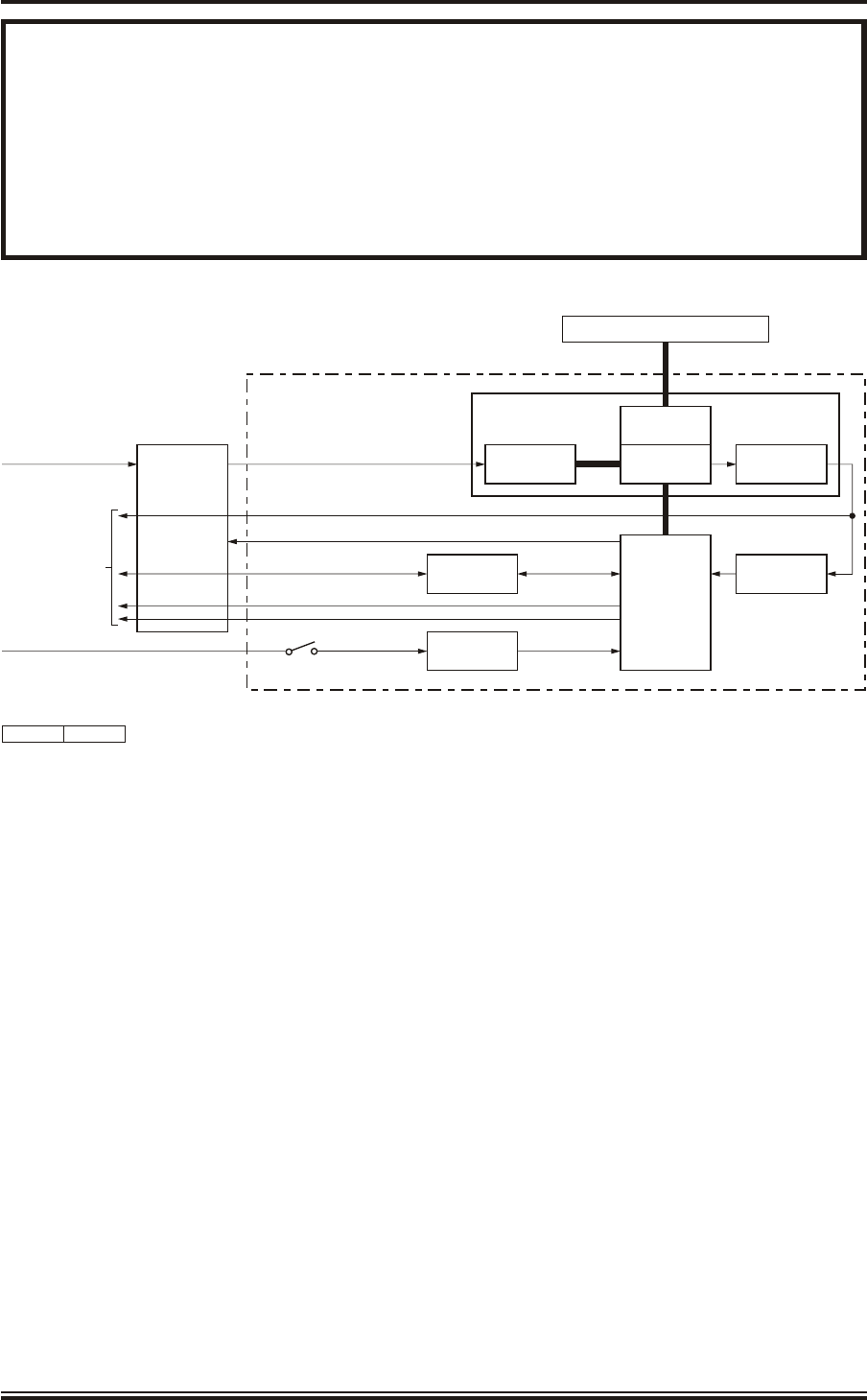
8The Upmast configuration is shown in Figure 1, and a typical implementation in Figure 2.
KH1264
Chap ter 1
Is sue 2 Page 1.3

SYS TEM DE SCRIP TION
Transceiver
9The transceiver electronics and the transceiver power supply are mounted in a cast
enclosure with one removable side cover, secured by seven captive bolts. The transceiver
electronics are contained in a unit mounted on the side of the enclosure and the power supply is
mounted on the base of the enclosure. The gearbox and motor are mounted on top of the
enclosure with the antenna secured to the top of the gearbox on a swing casting.
WARNING
THERE IS NO SAFETY SWITCH ON THE UPMAST TRANSCEIVER/TURNING
MECHANISM.
MAN ALOFT SAFETY IS PROVIDED BY AN ON/OFF KEYSWITCH ON THE
ASSOCIATED DRIVE CONTROL UNIT (FOR DETAILS SEE BELOW).
THE ON/OFF KEYSWITCH MUST BE SET TO OFF AND THE KEY REMOVED
BEFORE WORKING ON THE UPMAST TRANSCEIVER/TURNING
MECHANISM.
THE INVERTER IN THE DRIVE CONTROL UNIT MUST BE SET TO REMOTE
OPERATION DURING COMMISSIONING, OTHERWISE THE KEYSWITCH
FUNCTION WILL BE OVERRIDDEN.
10 The gearbox has a hollow output shaft through which the rotating joint (rojo) passes. The
output shaft also incorporates the mounting for the azimuth encoder, which provides
angular position information in the form of azimuth and heading line pulses.
11 The azimuth encoder provides azimuth and heading line pulses to the transceiver, which
uses the data internally. The azimuth and heading line pulses are also opto-isolated to
provide outputs to the display system. There are two sets of azimuth pulses in quadrature (each
set providing normal and inverse outputs with 1024 pulses per antenna revolution) and two
heading line pulses (normal and inverse outputs).
12 The motor and gearbox operate in conjunction with the Drive Control Unit to rotate the
antenna at speeds of up to 45 RPM in winds of up to 100 knots. The motor uses a variable
frequency 3-phase supply of 220 V between phases from the Drive Control Unit.
13 The Drive Control Unit uses the ship's single phase mains, which is fed via an inverter to
generate the 3-phase output. The frequency of the 3-phase output determines the antenna
rotation speed. The Drive Control Unit provides a 'soft start' by controlling the supply frequency
from 0 Hz to the operating frequency over a period of nominally 2 seconds.
KH1264
Chap ter 1
Page 1.4Is sue 2

14 The transceiver electronics comprise radar control and timing, waveform generator,
solid state transmitter, duplexer, low noise RF receiver, digital receiver, signal processor
and communications interface.
15 The waveform generator provides frequency modulated pulses at an intermediate
frequency (IF), whose characteristics are determined by the range modes. The IF pulses
are mixed with a local oscillator to provide an RF frequency signal to the solid state transmitter,
which provides an RF output at 170 W peak power to a duplexer located within the transceiver.
The signals from the duplexer are fed via a coaxial cable to the rotating joint and then to the
antenna.
16 Return signals from the antenna are fed through the rotating joint to the transceiver,
which routes the received signal via the duplexer to an internal low noise RF receiver,
digital receiver and signal processor. Sensitivity time control (STC) is applied to the RF receiver
to increase the dynamic range. The transceiver provides one analogue SYNC and one analogue
VIDEO coaxial output to the display system.
17 Internal monitoring of the transmitter and receiver performance is provided, therefore no
external components are required to ensure operation is satisfactory.
18 The power supply, located in the cast enclosure, provides the DC supplies for the
transceiver from the 110 V/220 V single phase mains input. The power supply is
autoranging, so no setting up is required for the input voltage.
Drive Con trol Unit
19 The Drive Control Unit provides a variable frequency 3 phase supply for the antenna
turning motor. The Drive Control Unit accepts a 220 V single phase mains supply. It
generates a 3 phase supply at either 25 Hz (for low speed antenna operation (22 RPM)) or 50 Hz
(for high speed antenna operation (44 RPM)), set up by links made on installation. The default
input frequency is 50 Hz to provide these output frequencies. If a different input frequency or
output frequency are used, the Drive Control Unit must be reprogrammed as described in
Chapter 5. The Drive Control Unit provides a 'soft start' of nominally 2 seconds, and a 'soft stop'
of nominally 10 seconds for the antenna. This reduces torque when the antenna is started and
stopped. If required, a transformer can be fitted to the mains input to enable the unit to be used
with 110 V mains.
20 The Drive Control Unit has two indicators and a switch on the top of the unit. The
indicators are MAINS ON, which is lit when the single phase mains input is present and
MOTOR ON, which is lit when the 3 phase output to the motor is present. The switch provides a
man aloft safety function, and is key operated. The key can only be removed when the switch is
set to OFF. When set to OFF, the 3 phase output is inhibited, thus preventing the antenna from
rotating. When set to ON the key is captive in the switch and the 3 phase power to the antenna
motor is enabled. Note that when the switch is set to OFF the MOTOR ON indicator will always
be unlit.
KH1264
Chap ter 1
Is sue 2 Page 1.5
WARNING
ALWAYS SET THE KEYSWITCH TO OFF AND REMOVE THE KEY WHEN
WORKING ON THE UPMAST TRANSCEIVER. THIS PREVENTS THE
ANTENNA FROM ROTATING.
THE INVERTER MUST BE SET TO REMOTE OPERATION DURING
COMMISSIONING, OTHERWISE THE KEYSWITCH FUNCTION WILL BE
OVERRIDDEN.
KH1264
Chap ter 1
Page 1.6Is sue 2
ANTENNA
ROTATING
JOINT
MOTOR
TRANSCEIVER
SYNC
VIDEO
TO/FROM DISPLAY
POWER GEARBOX
POWER UNIT
TRANSCEIVER ASSEMBLY
DTX-A3
1 PHASE MAINS IN
INVERTER START
AZIMUTH/HEADING LINE
DRIVE
CONTROL UNIT
GTX-A24
AZIMUTH
ENCODER
DC SUPPLIES
1 PHASE MAINS IN
TURNING
MECHANISM
CD-7616 ISSUE 1
CANBUS CONTROL/STATUS CAN ADAPTER
ON/OFF
SWITCH
AZIMUTH
INTERFACE
Figure 1 - SharpEyeTM Transceiver: Block Diagram
KH1264
Chap ter 1
Is sue 2 Page 1.7
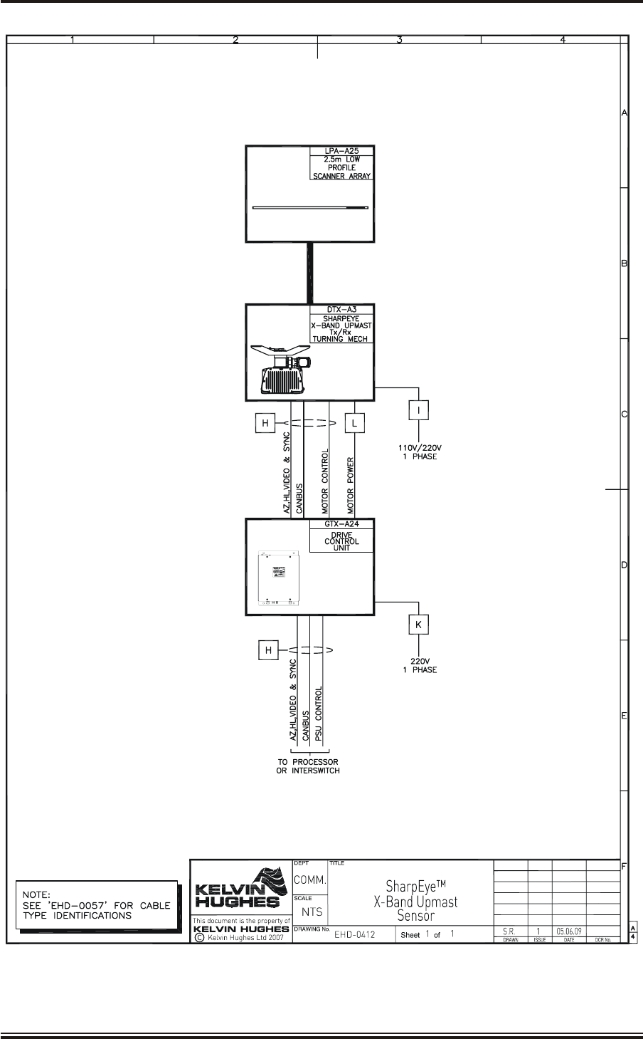
Figure 2 - SharpEyeTM Transceiver: Typical Configuration

THIS PAGE INTENTIONALLY BLANK
KH1264
Chap ter 1
Page 1.8Is sue 2


THIS PAGE INTENTIONALLY BLANK
KH1264
Chap ter 2
Page 2.2Is sue 2

CHAPTER 2
SPECIFICATION
TECH NI CAL SPEC I FI CA TIONS
1The technical specifications for the SharpEyeTM X-band Upmast Transceiver is as
follows:
Fea tures
Range resolution: 40 m
Dynamic range: ³ 100 dB (including Sensitivity Time Constant (STC))
ensures simultaneous detection of large and small
targets
Radar control: CANbus
System Type: Fully coherent
Trans mit ter
Frequency: 1 of 14 frequencies, each 20 MHz wide,
selectable in the band 9.22 GHz to 9.48 GHz
Type: Solid state power amplifier
RF Peak output power: 170 W minimum
Pulse width: 0.1 ms to 40 ms
Re ceiver
Type: Single channel, linear
Noise figure: 5 dB
Dynamic range: 65 dB at Analogue-to-Digital output, excluding STC
96 dB at Analogue-to-Digital output, with STC
Output: Analogue radar video and sync
KH1264
Chap ter 2
Is sue 2 Page 2.3

Sig nal Pro ces sor
Digital Phase Sensitive Detector
Digital Pulse Compression
Maximum instrumented range: 48 nm
Compressed pulse lengths: 0.1 ms or 0.2 ms
Antenna
Antenna Type: End fed slotted array
Polarisation: Horizontal
Turning Circle: 2.6 m
Horizontal beamwidth: 0.95°
Vertical beamwidth: 26°
Sidelobes: £ -30 dB, 1st sidelobe £ -26 dB typical
>10° sidelobes £ -33 dB typical
Antenna gain: 30 dB
Frequency range: 9.22 GHz to 9.48 GHz (centre frequencies)
Turn ing Mech a nism
Azimuth Data: 4096 pulses per antenna revolution
Heading Data: 1 pulse per revolution
Antenna rotation rates: 22 or 44 RPM for optimum update rate
Op er at ing Tem per a ture Ranges
Ambient Range Operational: -25°C to +55°C
Storage: -25°C to +70°C
Humidity 95% at +40°C
In put Power
Input Power Single Phase: 110 V/220 V 50/60 Hz AC input
(Transceiver) 440 VA max
Input Power Single Phase: 220 V 50/60 Hz AC input
(Drive Control Unit): (or 110 V via a transformer)
2200 VA max
KH1262
Chap ter 2
Page 2.4Is sue 2

CHAPTER 3
TECHNICAL DESCRIPTION
CON TENTS
Paragraph Page
IL LUS TRA TIONS
Figure Page
KH1264
Chap ter 3
Is sue 2 Page 3.1
1PHYS I CAL DESCRIPTION 3.3
1TRANS CEIVER 3.3
5DRIVE CON TROL UNIT 3.3
6FUNC TIONAL DE SCRIP TION 3.6
7TRANSCEIVER 3.6
7Mo tor and Gearbox 3.6
11 Trans ceiver (DTX-A115) 3.7
13 Timing Circuits and Azimuth Data Processing 3.7
15 Transmitter Circuits 3.7
18 Receiver Circuits 3.8
28 Operating States 3.9
29 Operating Range 3.9
30 Installation and Setting to Work Parameters 3.10
31 Monitoring 3.11
37 CAN Bus Interface 3.11
38 +15 V Supplies 3.11
39 Power Sup ply (45-690-0062-002) 3.11
40 DRIVE CON TROL UNIT (GTX-A24) 3.17
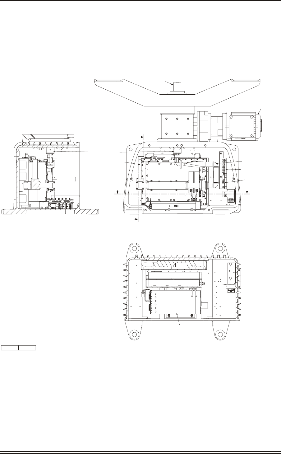
1Transceiver (DTX-A3): Module Locations 3.4
2Drive Control Unit (GTX-A24): Module Locations 3.5
3X-band Upmast Transceiver (DTX-A3): Functional Diagram 3.13/14
4X-band Upmast Transceiver (DTX-A3): Interconnection Diagram4 3.15/16
5Drive Control Unit (GTX-A24): Block Diagram 3.19

THIS PAGE INTENTIONALLY BLANK
KH1264
Chap ter 3
Page 3.2Is sue 2

CHAPTER 3
TECHNICAL DESCRIPTION
PHYS I CAL DESCRIPTION
TRANS CEIVER
1The transceiver is mounted in a cast enclosure with one removable side cover that allows
access to the transceiver electronics (refer to Figure 1). The cover is fitted with a seal to
prevent the ingress of moisture, and is secured to the cast enclosure by seven bolts. A strap
attached to the cover and enclosure prevents the cover from being dropped when removed from
the enclosure.
2The main units are:
(1) Antenna Motor and Gearbox, 55-100-0273-001
(2) Azimuth/Heading Line Encoder, GTX-A188
(3) RF Rotating Joint, 45-750-0034-001
(4) Swing Mount for the antenna, LPA-1129
(5) Transceiver, DTX-A115
(6) Power Supply, 45-690-0062-002
(7) Switch and CAN Adapter PCA Assembly, DTX-A150 comprising:
(a) CAN Adapter PCB, NNR-A981
(b) SharpEyeTM Azimuth Interface PCA, DTX-A151
3The Antenna Motor and Gearbox (55-100-0273-001) is mounted on top of the cast
enclosure with the antenna turning motor facing the rear of the enclosure. The antenna is
mounted on a swing casting (LPA-1129) fitted to the top of the gearbox. The gearbox has a
hollow output shaft through which the RF Rotating Joint (rojo) passes. The output shaft also
incorporates the mounting for the Azimuth Encoder (GTX-A188), which provides angular
position information in the form of azimuth and heading line pulses.
4The Transceiver (DTX-A115) is mounted on the side wall of the enclosure, the Power
Supply (DTX-A111) is mounted on the base of the enclosure, and the Switch and CAN
Adapter PCA Assembly (DTX-A150) is mounted on the rear end of the enclosure.
DRIVE CON TROL UNIT
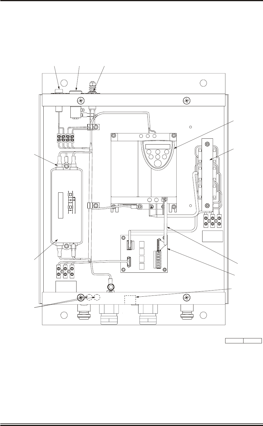
5The Drive Control Unit comprises a sheet metal rear plate which is formed to include the
top and bottom of the unit and also provides the bulkhead fixing points (refer to Figure 2).
The main sub-units, including the inverter, are bolted to the rear plate. A sheet metal
wrap-around cover is secured in position by four screws.
KH1264
Chap ter 3
Is sue 2 Page 3.3
KH1264
Chap ter 3
Page 3.4Is sue 2
SECTION ON A-A
SECTION ON B-B DOOR REMOVED FOR CLARITY
DTX-A115
KELVIN HUGHES
RADAR TRANSCEIVER
FMS090-5600
SERIAL No.
MOD:-
A
B
B
A
ENCODER AZ/HL
GTX-A188
X-BAND Tx ASSEMBLY
DTX-A115
POWER SUPPLY TYPE
XLC 503-POS A
45-690-0062-002
ROTATING JOINT
MOTOR & GEARBOX
3 PHASE
55-100-0273-001
INTERNAL
WAVEGUIDE ASSEMBLY
DTX-A170
CAN ADAPTOR PCB
NNR-A981
AZIMUTH INTERFACE PCB
DTX-A151
CD-7617 ISSUE 1
Figure 1 - Transceiver (DTX-A3): Module Locations
KH1264
Chap ter 3
Is sue 2 Page 3.5
CD-7275 ISSUE 1
TOSHIBA
PRG RUN RUN
MON
ENT STOP
E R/L1 S/L2
UT/1 VT/2 W/T
INVERTER
45-690-0033-001
PLA
DRIVE
INTERFACE PCB
GTX-A104
SCHAFFNER
FN2070M-12-06
P
N
E
P
N
1
6
NEON INDICATOR GREEN
45-6000-0076-001
LED INDICATOR GREEN
45-6000-0049-001
KEYSWITCH
45-613-4205
POWER INPUT
CABLEFORM
GTX-A217
POWER OUTPUT
CABLEFORM
GTX-A196
CONTROL
CABLEFORM
GTX-A197
MAINS FILTER
45-680-0028-001
U V W
OUTPUT
TB2
L E
TB1
N
MAINS INPUT
L N E 1TB4
12 WAY TAGBLOCK
VIDEO AND SYNC
COAXIAL CONNECTORS
Figure 2 - Drive Control Unit (GTX-A24): Module Locations

FUNC TIONAL DE SCRIP TION
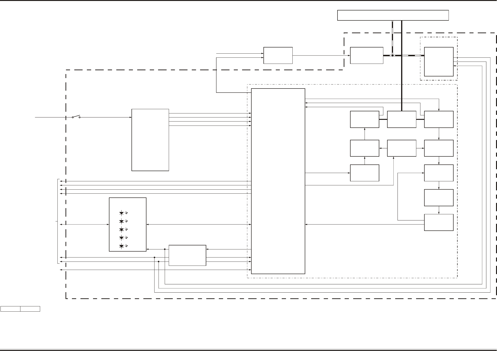
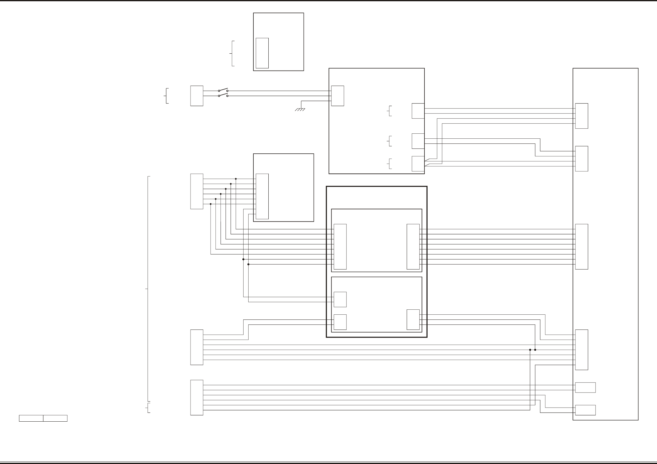
6Functional diagrams of the transceiver and antenna are shown in Figure 3 and the
interconnections in Figure 4.
TRANSCEIVER
Mo tor and Gearbox
7The antenna motor is driven by a 3 phase supply from the inverter in the Drive Control
Unit. The Drive Control Unit is configured to provide a soft start and a soft stop for the
motor, so that the motor takes a few seconds to reach normal antenna rotation speed and a few
seconds to slow down when stopped. This reduces the start up and stopping torque on the motor.
The motor is connected to the antenna by the gearbox which provides the drive to the antenna.
8The Azimuth and Heading Line pulses are generated by the Azimuth Encoder, which is
mounted on the output shaft of the gearbox. Part of the Azimuth Encoder rotates with the
gearbox and part remains stationary with the enclosure. The Azimuth Encoder uses an optical
disc with sensors.
9Two heading line pulses (heading line and inverse heading line) and two sets of 1024
pulses per revolution azimuth pulses (each set comprising azimuth and inverse azimuth)
are produced for each rotation of the antenna. The two sets of azimuth pulses are produced in
quadrature (called Q1 and Q2 pulses), with Q2 lagging Q1 pulses by 90° when the antenna
rotates in the normal direction. This allows the azimuth data to be used to detect reverse rotation
of the antenna (which may occur due to windage when the motor is switched off) as Q2 pulses
lead Q1 pulses by 90° when the antenna starts to rotate in the reverse direction. The Azimuth
Encoder is supplied with +15 V, which is used to generate azimuth and heading line output
pulses of +15 V. The pulses are passed directly to the display system via TB1 and also to the
SharpEyeTM Azimuth Interface PCA (DTX-A151), which opto-isolates the signals before they
are routed to the Transceiver (DTX-A115).
10 The phase of the azimuth inputs for normal and reverse rotation is shown below.
KH1264
Chap ter 3
Page 3.6Is sue 2
Q1
Q3
Q2
Q4
Q2 TO Q1
90 DEGREE
PHASE LAG
Q2 TO Q1
90 DEGREE
PHASE LEAD
ANTENNA
DIRECTION
REVERSES

Trans ceiver (DTX-A115)
11 The transceiver uses solid state components and provides a signal generator and
frequency synthesiser, up-converter, solid state RF power amplifier, duplexer, low noise
RF receiver, down-converter, digital receiver, digital signal processor and a LAN interface. The
transceiver produces a peak power output of ³170 W. The solid state design provides excellent
reliability and has no lifed items. Note that the unit is not repairable in the field and must be
returned to the manufacturer for repair. The following description is for information only.
12 The transceiver is capable of transmitting and receiving pulses of RF energy whose
centre frequency is contained in the band 9.22 to 9.48 GHz and is capable of inhibiting
the transmission of pulses of RF energy over an azimuth sector defined by the display system.
Timing Circuits and Azimuth Data Processing
13 There are two reference clock outputs, which output squarewaves with a frequency of
80 MHz ± 80 Hz. The local oscillator is phase locked to the reference clock. All the clock
and timing circuits are derived as multiples of this reference clock.
14 The local oscillator produces a sinusoidal output with a frequency of 640 MHz ± 1.3 kHz.
This is used with the transmit and receive circuits for up- and down-conversion.
Transmitter Circuits
15 The signal generation and frequency synthesis circuits use a waveform generator that
provides frequency modulated pulses at an intermediate frequency. The characteristics
of the pulses are determined by the range and rotation modes, i.e. the instrumented range selected
and the antenna rotation speed selected. The waveform generator employs digital synthesis
techniques and outputs frequency modulated pulses with a centre frequency of 60 MHz ±200 Hz.
The within pulse frequency modulation is phase contiguous.
16 The up-converter converts the IF signals from the waveform generator to RF frequency
in three stages. The bandwidth of the first intermediate frequencies within the up
converter are 60 MHz ±12 MHz and 140 MHz ±12 MHz. The bandwidth of the second
intermediate frequencies within the up converter are 500 MHz ±20 MHz and 580 MHz
±20 MHz. The bandwidth of the third intermediate frequencies within the up converter are
1140 MHz ±20 MHz and 1220 MHz ±20 MHz.
17 The RF frequency signal is fed to the solid state power amplifier, which provides an RF
output at ³170 W peak power to a duplexer located within the transceiver. Note that the
power amplifier stage is switched off between sending each of the pulses in order to maximise
receiver sensitivity. The signals from the duplexer are fed via a coaxial cable to the rotating joint
and then to the antenna.
KH1264
Chap ter 3
Is sue 2 Page 3.7

Receiver Circuits
18 Return signals from the antenna are fed through the rotating joint to the transceiver,
which routes the received signal via the duplexer to an internal low noise RF receiver,
digital receiver and signal processor.
19 Sensitivity Time Control (STC) is applied to the low noise RF receiver to increase the
dynamic range of the receiver. The noise figure of the receiver is £4 dB, measured at the
output of the analogue to digital converter. The low noise receiver contains the capability to
adjust the mean noise level prior to analogue to digital conversion.
20 The output from the low noise RF receiver is converted to a third intermediate frequency
in three stages. The bandwidth of the first intermediate frequency is 1220 MHz ±20 MHz.
The bandwidth of the second intermediate frequency is 580 MHz ±20 MHz. The bandwidth of
the third intermediate frequency is 60 MHz ±12 MHz.
21 The intermediate frequency is applied to an analogue-to-digital converter which outputs
14 bit two’s complement digitised samples to the digital receiver. The centre frequency
of the digitised samples is 20 MHz ±80 Hz and the instantaneous bandwidth is £20 MHz.
22 The digital receiver translates the signals to the baseband frequency and provides
In-phase and Quadrature (I and Q) outputs to the digital signal processor. The in-phase
and quadrature phase outputs of the digital receiver are both rounded to 18 bits, and the format of
the output is two's complement.
23 The digital signal processor uses digital pulse compression before applying the signals to
the limiting and compensation function. Motion compensation removes the effect of own
ship motion from the received signal vector. The limiting and motion compensation function has
a Doppler output channel and a Logarithmic output channel.
24 The Doppler channel is currently not implemented.
25 The input to the Logarithmic channel is used for video processing. The video processing
function aligns the amplitude data into a contiguous range ordered data stream, aligns the
single bit detection video into a contiguous range ordered data stream and aligns the logarithmic
amplitude data into a contiguous range ordered data stream.
26 The video is converted to analogue video for output to conventional display systems, e.g.
Nucleus 3, Manta and MantaDigital. In the future digital video will also be output from
the LAN link.
27 Due to the characteristics of RACON systems, the processing applied to targets and
objects within the digital signal processor is not suitable for the detection of a RACON.
To solve this, a specific RACON processing channel is included. This enables RACON signals
to be processed and integrated into the surface picture processed video output.
KH1264
Chap ter 3
Page 3.8Is sue 2

Operating States
28 The transceiver has the following six operating states:
(1) Off. In this state power is not applied to the transceiver and it is switched off.
(2) Initialise. When power is applied to the transceiver it enters initialise state. The
transceiver automatically loads any software or configuration files and supplies
DC power to the azimuth encoder. On completion of initialisation the transceiver
switches to Standby state.
(3) Standby. In this state the transceiver establishes communication with the display
system and reports its status to the display system. The transceiver receives and
acts on commands from the display system and provides azimuth and heading
line data from the encoder to the display system. The transceiver does not radiate
RF in this state.
(4) Transmit. On receipt of a Run command from the display system, provided the
display system has defined all the operating conditions, the transceiver switches
from Standby to Run state. The transceiver initially outputs an RF signal into the
antenna at low power. This enables the VSWR to be checked without the risk of
damage to the transceiver, e.g. from an open circuit into the antenna. If the VSWR
is within limits then the transceiver automatically switches to full power. If the
VSWR is high, indicating an antenna fault, a warning message is sent to the
display system and the transceiver does not radiate on full power. The radar
returns are then processed to provide radar video to the display system. Note that
the time from switch on to being ready to enter the run state is less than 2 minutes.
(5) Degraded. The transceiver continuously runs background performance checks
on forward power, reverse power and receiver sensitivity. If any of these
parameters is outside predetermined levels a warning message is sent to the
display system indicating the nature of the fault. The transceiver continues to
operate, but with reduced performance and functionality. The fault should be
investigated at the earliest opportunity.
(6) Fault. If the performance or functionality is degraded such that the transceiver
cannot operate it enters the fault state and a fault message is sent to the display
system. The transceiver stops radiating RF and there is no video to the display.
Operating Range
29 In either the Transmit or Degraded states the radar operates in one surface picture mode
with a range of interest of 48 nm. The operating range is determined by the Range Scales
selected on the display. 24 nm mode is applied when a range scale of 24 nm or less is selected.
48 nm operating range is selected for range scales greater than 24 nm.
KH1264
Chap ter 3
Is sue 2 Page 3.9

Installation and Setting to Work Parameters
30 The SharpEyeTM Transceiver contains a number of operational settings that are set up
during system installation and setting to work. These operational settings are:
(1) Rotation Rate. The transceiver supports 2 nominal antenna rotation rates, 22 rpm
and 44 rpm. System behaviour and performance varies depending upon which
rotation rate is selected as the system parameters are adjusted for the different
rotation rates.
(2) Operating Frequency. The transceiver contains 14 pre-set transmission
frequencies within the operating frequency band. The frequency used for a
particular system is set during system installation and setting to work. The centre
frequencies of each RF band are:
(a) 9.22GHz ±15 kHz.
(b) 9.24GHz ±15 kHz.
(c) 9.26GHz ±15 kHz.
(d) 9.28GHz ±15 kHz.
(e) 9.30GHz ±15 kHz.
(f) 9.32GHz ±15 kHz.
(g) 9.34GHz ±15 kHz.
(h) 9.36GHz ±15 kHz.
(i) 9.38GHz ±15 kHz.
(j) 9.40GHz ±15 kHz.
(k) 9.42GHz ±15 kHz.
(l) 9.44GHz ±15 kHz.
(m) 9.46GHz ±15 kHz.
(n) 9.48GHz ±15 kHz.
(3) Transmit Inhibit Sector. The transceiver provides one blanking sector that is
configured via the display system. The radar does not transmit RF energy within
the blanking sector.
KH1264
Chap ter 3
Page 3.10 Is sue 2

Monitoring
31 If the RF output power falls below 100 W the transceiver sends an RF Power warning
message to the display system and switches to the Degraded state of operation.
32 If the VSWR on the RF output is above 2.0:1 the transceiver sends an Antenna VSWR
warning message to the display system and switches to the Degraded state of operation.
33 If the minimum detectable signal rises above a preset level the transceiver sends a
Receiver Sensitivity warning message to the display system and switches to the
Degraded state of operation.
34 If the transceiver detects hardware faults (frequency synthesis or phase locked oscillator
failure), it sends a warning message to the display system and switches to the Degraded
state of operation.
35 If communication between the transceiver and the display system is lost for > 5 seconds
the transceiver switches to the fault state.
36 If the temperature of the RF power transistors in the transceiver exceeds a predetermined
limit, the transceiver sends an Overtemperature warning to the display system and
switches to the Degraded state. If the temperature exceeds a further preset limit the transceiver
switches to the Fault state. As the temperature drops below the predetermined limits the
transceiver returns to the Degraded state and then to normal Transmit operation.
CAN Bus Interface
37 The CAN bus signals to and from the display system are routed via the CAN Adapter
PCB (NNR-A981), which interfaces the CAN bus to the RS232 interface on the
Transceiver (DTX-A115). The CAN Adapter PCB converts the RS232 signals from the
Transceiver into CAN bus signals for routing to the display, and converts the CAN bus signals
from the display to RS232 signals for application to the transceiver.
+15 V Supplies
38 +15 V from the transceiver is routed to the SharpEyeTM Azimuth Interface PCB
(DTX-A151). The SharpEyeTM Azimuth Interface PCB routes the +15 V to the Encoder
and the CAN Adapter PCB (NNR-A981).
Power Sup ply (45-690-0062-002)
39 The transceiver uses 110 V or 220 V single phase mains, which is passed through a mains
filter before application to the Switched Mode Power Supply. The Power Supply
provides the following DC supplies for the transceiver module:
(1) +3.3 V at 5.0 A for the digital processing circuits.
(2) +15 V at 5.0 A for the digital processing and amplifier circuits.
(3) +13 V at 6.0 A for the amplifier circuits.
KH1264
Chap ter 3
Is sue 2 Page 3.11

THIS PAGE INTENTIONALLY BLANK
KH1264
Chap ter 3
Page 3.12 Is sue 2
KH1264
Chap ter 3
Is sue 2 Page 3.13/14
X-BAND ANTENNA
AZIMUTH/
HEADING LINE
GENERATION
BALANCED HL
+15V
AERIAL
TURNING MOTOR
55-100-0273-001
X-BAND UPMAST TRANSMITTER/RECEIVER
DTX-A3
Tx SOLID STATE
RF AMPLIFIER
Rx RF
AMPLIFIER
TRANSCEIVER
DTX-A115
DIGITAL VIDEO
TO/FROM DISPLAY SYSTEM
(NTO IMPLEMENTED AT PRESENT)
DUPLEXER
ENCODER AZ/HL
GTX-A188
DRIVE
CONTROL UNIT
GTX-A24
1 PHASE MAINS SUPPLY
MOTOR ON/OFF 3 PHASE TO MOTOR
CD-7618 ISSUE 1
SENSITIVITY TIME CONTROL
REVERSE POWER
FORWARD POWER
RF
IF/RF
UPCONVERSION
LOCAL
OSCILLATORS
& SPLITTERS
RF
RF/IF DOWN
CONVERSION
ANALOGUE
TO DIGITAL
CONVERTER
WAVEFORM
GENERATOR
PULSE/RANGE SETTING
CHANNEL SELECT
INTERFACE CONTROL
& TIMING CIRCUITS
DIGITAL
RECEIVER
DIGITAL
SIGNAL
PROCESSING
NOISE INJECT
POWER SUPPLY
45-690-0062-002
+3.3V DIGITAL
+15V DIGITAL
+13V AMPLIFIER
+13V AMPLIFIER
1 PHASE
MAINS SUPPLY
ON/OFF
SWITCH
SW1
AZ (NOT USED)
HL (NOT USED)
VIDEO
SYNC
CAN ADAPTER PCB
NNR-A981
RUNNING
D13
+15V
D1
+15V
D12
RS232
+24V
D16
+5V
D38
CAN BUS
TO/FROM DISPLAY SYSTEM
VIA DRIVE CONTROL UNIT
SHARPEYE
AZIMUTH
INTERFACE
DTX-A151
PHASE & QUADRATURE AZ
BALANCED HL
ETHERNET INTERFACE (FUTURE EXPANSION)
PHASE &
QUADRATURE AZ
BALANCED HL
+15V
PHASE &
QUADRATURE AZ
+15V
Figure 3 X-band Upmast Transceiver (DTX-A3): Functional Diagram Figure 3
KH1264
Chap ter 3
Is sue 2 Page 3.15/16
CD-7619 ISSUE 1
SHARPEYE X-BAND
Tx ASSEMBLY
DTX-A115
PL2
A1
A2
A4
A3
0V (3.3V)
3.3V
0V (15V)
15V
SK1
1
2
3
4
5
6
7
8
SK7
A1
A2
A4
A3
LIVE
NEUTRAL
EARTH
110V/220V
MAINS INPUT
CAN ADAPTER PCB
NNR-A981
3
2
6
5
9
8
12
11
SHARPEYE
AZIMUTH INTERFACE
DTX-A151 PL2
1
2
PLA
CAN HI
CAN LO
1
2
3
PLJ
RS232TX
RS232RX
GND
1
2
3
4
5
6
7
8
AZ1
nAZ1
AZ2
nAZ2
HL
nHL
+15V
0V
PL1
SWITCH & CAN
ADAPTER PCA ASSEMBLY
DTX-A150
0V (13V)
13V
0V (15V)
15V
nAZ1
AZ1
nAZ2
AZ2
nHL
HL
+ve
0V
TB1
1
2
3
4
5
6
AZ1
nAZ1
AZ2
nAZ2
HL
nHL
POWER SUPPLY
45-690-0062-002
AJ4
1
2
DJ4/EJ4
1
2
FJ4
1
2
J1
L
N
E
LIVE
NEUTRAL
EARTH
0V (3.3V)
3.3V
MODULE A
0V (13V)
13V
MODULE B,C,D,E
0V (15V)
15V
MODULE F
SW1
TB5
1
2
3
PL1
1
2
3
4
5
6
TB2
CAN HI
CAN LO
CAN SCREEN
GROUND
HEADING LINE
AZIMUTH
VIDEO (INNER)
VIDEO (SCREEN)
SYNC (INNER)
SYNC (SCREEN)
MOTOR ON/OFF
MOTOR GND (RTN)
TB3
1
2
3
4
5
6
4
1
5
3
8
9
6
RS232RX
RS232TX
CAN SCREEN
GROUND
HEADING LINE
AZIMUTH
MOTOR ON/OFF
VIDEO
(COAX)
VIDEO
SCREEN
INNER
SCREEN
SYNC
(COAX)
SYNC
SCREEN
INNER
SCREEN
AERIAL MOTOR
3-PHASE
55-100-0273-001
U
V
W
E
R
Y
B
SCREEN
3-PHASE FROM
DRIVE CONTROL UNIT
TO/FROM DISPLAY SYSTEM
VIA DRIVE CONTROL UNIT
TO DRIVE CONTROL UNIT
1
2
3
4
5
6
7
8
AZ1
nAZ1
AZ2
nAZ2
HL
nHL
+15V
0V
ENCODER
ENCODER AZ/HL
GTX-A188
PLC
1
2
+15V
0V
nAZ1
AZ1
nAZ2
AZ2
nHL
HL
+ve
0V
BJ4/CJ4
Figure 4 X-band Upmast Transceiver (DTX-A3): Interconnection Diagram Figure 4

DRIVE CON TROL UNIT (GTX-A24)
40 The drive control unit provides 3 phase supplies for the antenna turning motor in the
SharpEyeTM Upmast Transceiver. It accepts a 220 V single phase mains supply and
generates a 3 phase supply at either 25 Hz or 50 Hz with the frequency set internally, either of
which may be selected from the display, or by physical wire links on the Drive Control Unit.
25 Hz is used to provide an antenna speed of 22 rpm and 50 Hz is used to provide an antenna
speed of 44 rpm. If required, a transformer can be fitted to the mains input to enable the unit to be
used with 110 V mains.
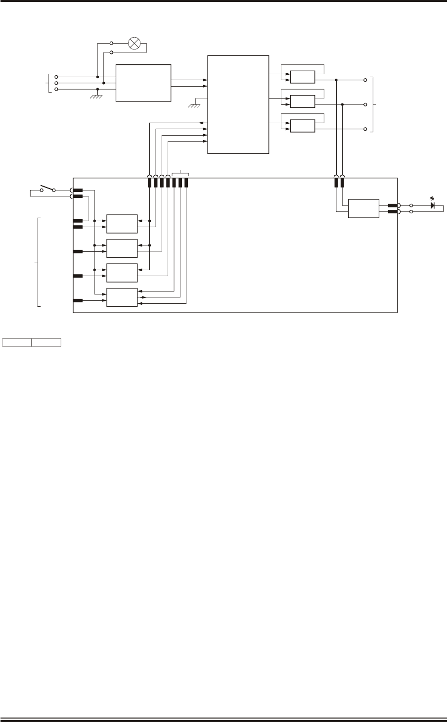
41 Figure 5 shows the interconnections within the Drive Control Unit. The Drive Control
Unit comprises:
(1) Inverter (45-690-0033-001)
(2) Drive Interface PCB (GTX-A104)
(3) Mains input filter (part of Power Input Cableform GTX-A217)
(4) Man Aloft Keyswitch (45-613-4205)
(5) Output filters (ferrite cores - part of Power Output Cableform GTX-A196)
42 The presence of the mains input is indicated by the MAINS ON neon indicator (LP1) on
the top of the unit being lit.
43 The mains input is passed through the input filter, which slows down the rate of rise of
current input pulses to reduce the generation of interference. The mains is then applied to
the inverter, which converts the single-phase input at 50/60 Hz into 3-phase at 0 Hz to 120 Hz
(variable). The 3-phase output is generated as switched mode power pulses. These pulses are at
the peak output voltage, which is approximately 320 V with 5 kHz switching frequency. The
effective rms voltage at the output varies from 130 V to 230 V AC depending on the antenna
motor load.
44 The output frequency sets the speed of antenna rotation. The output frequency is set to
25 Hz for 22 rpm and 50 Hz for 44 rpm antenna rotation speed. The speed is set at the
inverter on installation and if the inverter is replaced, the new inverter must be correctly set after
repair. Note that the inverter is set on installation to provide a 25 Hz or 50 Hz output using wire
links. The output frequency is also dependent on the input frequency, so that the new inverter
must be programmed for 50 Hz or 60 Hz input as described in Chapter 5. Most of the settings are
the manufacturer's defaults, but others must be set up as specified.
45 The inverter is set to provide an acceleration time of 2 seconds before reaching full speed,
this provides a soft-start function for the antenna on start up. When the power is switched
off, the inverter provides a deceleration time of 10 seconds to slow the antenna rotation. These
functions reduce the torque on the antenna during starting and stopping.
46 The Drive Interface PCB (GTX-A104) provides the control interface to the inverter. It
also provides the interface to external control lines to allow one of the antenna speeds to
be selected by wire links on installation. It uses opto-isolators to allow the control signals to the
inverter to be compatible with the inverter.
KH1264
Chap ter 3
Is sue 2 Page 3.17

47 The inverter is switched on by applying +12 V to +28 V across PLA pins 1 and 2 on the
Drive Control PCB. The positive voltage is routed via PLC pin 5 to the Man Aloft
Keyswitch (SW1), which is located on the top of the unit. This switch disables the +12 V to +28 V
to the inverter when set to the OFF position, thus switching the inverter off, regardless of the
input condition, provided the inverter has been set for remote operation. The key is removable in
the OFF position only and is captive in the ON position. This enables antenna rotation to be
inhibited to allow safe man aloft working.
WARNING
THE INVERTER MUST BE SET TO REMOTE OPERATION TO ENABLE THE
KEYSWITCH TO SWITCH THE INVERTER ON AND OFF. UNDER NO
CIRCUMSTANCES SET THE INVERTER TO LOCAL OPERATION AS THIS
WILL OVERRIDE THE SAFETY FUNCTION.
48 The voltage from the keyswitch is routed to PLC pin 6 on the Drive Control PCB. When
the +12 V to +28 V is present at PLC pin 6, an opto-isolator on the Drive Control PCB is
switched on, linking PLB pins 1 and 2 to switch the inverter on. When the +12 V to +28 V is not
present at PLC pin 6, either by the absence of the input on PLA pin 1 or by the keyswitch being set
to OFF, the opto-isolator is switched off and PLB pins 1 and 2 are open circuit, thus switching the
inverter off.
49 A MOTOR ON LED (D1) on top of the unit is lit when 3-phase power is available to the
motor from the inverter. Two of the phases from the inverter are passed to the Drive
Control PCB, which converts the signal to a DC level suitable for the LED.
50 Each output wire passes through a ferrite core to reduce the rate of rise of current, which
reduces the generation of interference. The ferrite cores form part of the output cable.
51 The inverter is used with Speed 1 and Speed 2 inputs, which operate in the same way, so
only Speed 1 input is described. Speed 1 switches on an opto-isolator when PLA pin 3 is
connected to the negative side of the start input (PLA pin 2) and +12 V to +28 V is present at PLC
pin 6. The output is used to link the appropriate inverter speed selector terminals. Using Speed 1
input gives a two speed selection, depending on whether PLA pin 3 is connected to PLA pin 2 or
is open circuit. In this application PLA pin 3 is linked to PLA pin 2 for low speed and is open
circuit for high speed. Speed 2 (PLA pin 4) is always linked to PLA pin 2.
52 Future enhancements will allow the Drive Control Unit to provide the facility to select up
to four antenna speeds, by controlling Speed 1 and Speed 2 inputs from an external
source. This will allow one of up to four preset speeds to be selected to meet the operational
requirements of the system.
KH1264
Chap ter 3
Page 3.18 Is sue 2
KH1264
Chap ter 3
Is sue 2 Page 3.19
CD-7279 ISSUE 1
MAINS FILTER
45-680-0028-001
L1
L
N
E
L
N
TB1
220V MAINS
INPUT
1
2
3
LIVE
NEUTRAL
EARTH
TB3
1
2
MAINS ON
LP1
INVERTER
45-690-0033-001
L1
L1
L2
L3(N) NOT USED
PE
T1 L2
TB2
1
2
3
220V 3 PHASE OUTPUT
TO MOTOR
L3
L4
T2
T3
COMMON
FORWARD
SPEED 1
SPEED 2
NOT
USED
1
2
3
4
6
7
8
PLB
P15
F
S1
S2
+15V O/P
FORWARD
SPEED 1
SPEED 2
FERRITE CORES
(2 TURNS THROUGH
EACH RING)
PLD
3
1
PLC
2
1
LED
DRIVER
TB3
3
4
OPTO-
ISOLATOR DRIVE INTERFACE PCB
GTX-A104
OPTO-
ISOLATOR
OPTO-
ISOLATOR
OPTO-
ISOLATOR
+V
F ADJUST
-V
PLC6
5
PLA1
2
3
4
5
START (27V)
START (RTN)
SPEED 1
SPEED 2
SPEED 3
Tx CONTROL
KEYSWITCH
SW1
MOTOR ON
D1
NOTE: TAGBLOCK 1TB4 AND COAX CONNECTORS NOT SHOWN
Figure 5 - Drive Control Unit (GTX-A24): Block Diagram

THIS PAGE INTENTIONALLY BLANK
KH1264
Chap ter 3
Page 3.20 Is sue 2

CHAPTER 4
INSTALLATION
CON TENTS
Paragraph Page
TA BLES
Table Page
KH1264
Chap ter 4
Is sue 2 Page 4.1
1GEN ERAL 4.3
4COM PASS SAFE DIS TANCES 4.3
5TRANS CEIVER 4.3
7SAFETY NOTES 4.4
13 EQUIP MENT LO CA TION 4.5
13 UPMAST TRANS CEIVER (DTX-A3) 4.5
18 DRIVE CON TROL UNIT (GTX-A24)4.5
20 OP TIONAL MAINS ISO LA TOR (80-261-600) 4.5
21 IN STAL LA TION 4.6
21 UPMAST TRANS CEIVER (DTX-A3) 4.6
27 Fit ting the Upmast Trans ceiver to the Ship 4.7
28 Fit ting the Low Pro file Antenna 4.7
30 DRIVE CON TROL UNIT (GTX-A24) 4.13
31 OP TIONAL MAINS ISO LA TOR (80-261-600) 4.14
32 ELEC TRI CAL CON NEC TION 4.15
32 CA BLE SPEC I FI CA TIONS 4.15
34 14 Core Com pos ite Ca ble 4.16
35 Small Multi-Core Ca bles 4.17
37 Power Ca bles 4.17
2-Core (Power): 4.17
3-Core (Power): 4.17
38 GEN ERAL 4.18
44 COVER RE MOVAL 4.18
45 Upmast Trans ceiver (DTX-A3) 4.18
46 Drive Con trol Unit (GTX-A24)4.18
47 Op tional Mains Iso la tor (80-261-600) 4.18
48 WIR ING DI A GRAMS 4.22
50 CHECKS AFTER FITTING 4.22
1Cable Specification 4.15
214-Core Cable Colour Abbreviations 4.16

CON TENTS (con tin ued)
LIST OF IL LUS TRA TIONS
Figure Page
KH1264
Chap ter 4
Page 4.2Is sue 2
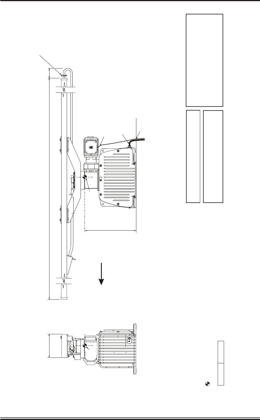
1Transceiver (DTX-A3): Installation Dimensions 4.9
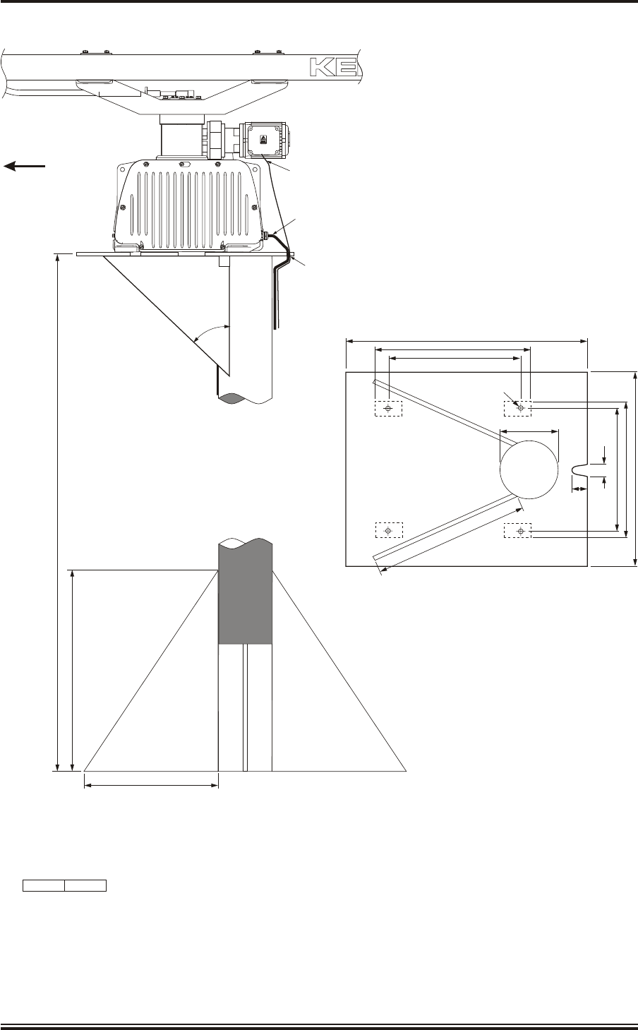
2Transceiver (DTX-A3): Mast Mounting 4.10
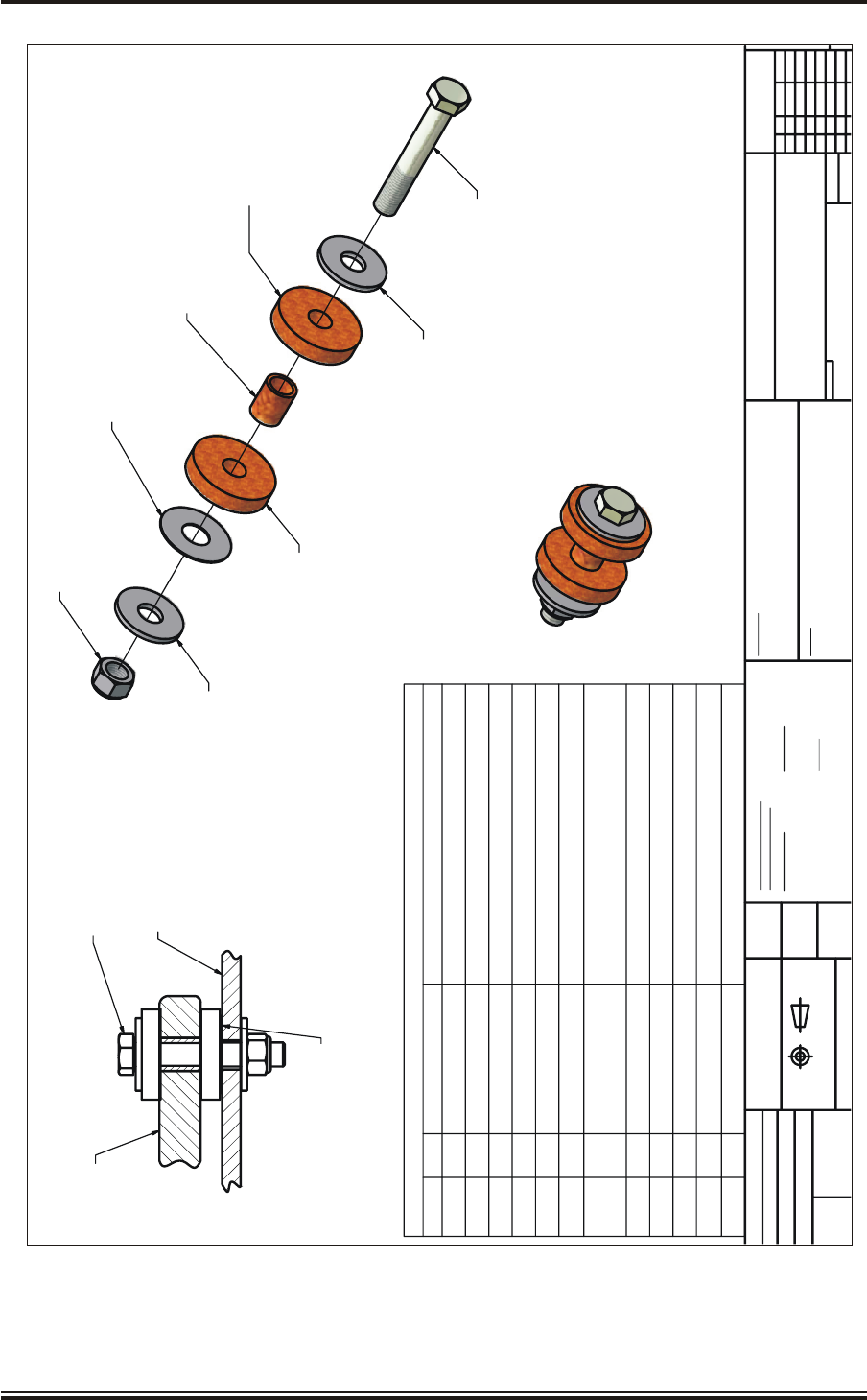
3Transceiver (DTX-A3): Fitting Kit 4.11
4Suggested Antenna Lifting Arrangement 4.12
5Drive Control Unit (GTX-A24): Installation Dimensions 4.13
6Mains Isolator: Installation Dimensions 4.14
7Transceiver (DTX-A3): Cableform Routing 4.19
8Drive Control Unit (GTX-A24): Cableform Routing 4.20
9Cable Gland: Assembly 4.21
10 Transceiver (DTX-A3): External Connections 4.23

CHAPTER 4
INSTALLATION
GEN ERAL
1This section provides installation information for SharpEyeTM X-band Upmast
Transceiver.
2Kelvin Hughes, or appointed agents, contracts only to supply the equipment, supervise
the installation and final connection of the equipment. The installation must be made by a
fully qualified Kelvin Hughes Radar Engineer.
3Forward planning for positioning the various units of the Radar must be made before any
installation work is carried out. A full survey is required in order to establish the ship’s
fitment. This may be arranged with the Technical Department of Kelvin Hughes or one of the
approved agencies. Details of Agencies worldwide can be found in Publication KH 401.
COM PASS SAFE DIS TANCES
4Compass safe distances are stated on labels on all units and are as follows:
Standard Compass Limit Steering Compass Limit
5.4°/H 18°/H
Compass Safe Distance Compass Safe Distance
SharpEyeTM Transceiver: 120 cm 52 cm
Drive Control Unit: 246 cm 154 cm
TRANS CEIVER
5One version of upmast transceiver is available, type DTX-A3, which is used with the
Low Profile Antenna (LPA) (LPA-A25).
6The transceiver is used with a bulkhead mounted Drive Control Unit (GTX-A24), which
provides the 3-phase power for the antenna turning motor.
KH1264
Chap ter 4
Is sue 2 Page 4.3

SAFETY NOTES
Observe the Health and Safety Notices at the front of this manual. In
particular, the procedures given in the Code of Safe Working Practices
CP225 MUST be followed. Failure to follow these procedures and to
complete and return the Warranty card will invalidate the warranty on the
equipment.
7Safety personnel must ensure that persons do not encroach on the area of work.
8Electrical supplies are to be isolated to any part of the platform when mounting an upmast
transceiver/turning mechanism. A suitable safety platform or harness should be used to
avoid personal injury when working aloft.
9Electrical supplies in the vicinity of the transceiver are to be isolated during installation.
10 A working platform is to be provided for installing or servicing the assembly. This should
be positioned approximately a metre below the base of the Upmast Transceiver housing
with a guard rail surrounding it.
11 The Upmast Transceiver must be hoisted to the fixing position using a secured block and
tackle or rope strops.
12 The Upmast Transceiver MUST NOT be lifted by the array, but the complete unit
secured and hoisted evenly. The antenna must be installed after the upmast transceiver
has been installed.
WARNING
WHEN WORKING ON THE UPMAST TRANSCEIVER ALWAYS ENSURE THE
ON/OFF SWITCH ON THE DRIVE CONTROL UNIT IS SET TO OFF AND THE
KEY IS WITHDRAWN. THE KEY SHOULD BE RETAINED BY THE
INSTALLER WHEN WORKING ALOFT. REMOVAL OF THE KEY PREVENTS
THE ANTENNA FROM ROTATING.
THE INVERTER MUST BE SET TO REMOTE OPERATION DURING
COMMISSIONING, OTHERWISE THE KEYSWITCH FUNCTION WILL BE
OVERRIDDEN.
THE UPMAST TRANSCEIVER USES A 110 V/220 V MAINS SUPPLY FOR THE
TRANSCEIVER ELECTRONICS. THIS SUPPLY IS NOT ISOLATED BY THE
KEYSWITCH IN THE DRIVE CONTROL UNIT, AND MUST BE ISOLATED AT
THE MAINS ISOLATOR.
KH1264
Chap ter 4
Page 4.4Is sue 2

EQUIP MENT LO CA TION
UPMAST TRANS CEIVER (DTX-A3)
13 The Upmast Transceiver should be installed in such a position where Blind Arcs, caused
by obstructions, i.e. masts, funnels etc, are eliminated or minimised. Funnels, crosstrees
and other large obstructions can also reflect energy and give rise to spurious echo returns
especially in close proximity to land. Positioning the antenna close to funnels and exhaust gases
can adversely affect antenna performance.
14 The Upmast Transceiver is to be mounted on a rigid platform, which is positioned so that
the rotating antenna is clear of other structures.
15 The primary consideration must be the strength of the support for the Upmast
Transceiver/Antenna assembly. Details of the requirement are described in the following
sub-paragraphs:
(1) The antenna must be mounted more than 914 mm (3 ft) above any flat surface
greater than the diameter swept by the antenna. It must not be positioned in close
proximity of any magnetic compass or D/F aerial etc.
(2) Masts, sampsons, posts and rigging of more than 0.6 m (2 ft) diameter can cause
blind sectors. Increasing the distance between the antenna unit and these objects
will reduce the blind sectors that inhibit a good radar picture.
16 The Upmast Transceiver must not be mounted where the temperature exceeds 70oC.
17 The Upmast Transceiver must be kept clear of ship’s flexible communication aerials to
avoid damage to both.
DRIVE CON TROL UNIT (GTX-A24)
18 The Drive Control Unit is designed for bulkhead mounting and must be sited as near the
Transceiver as possible, the maximum cable run between the Drive Control Unit and
Transceiver is 65 m.
19 The Drive Control Unit must be sited to allow removal of the front cover, access to the
cable glands and removal of the key from the keyswitch, which is essential when working
aloft.
OP TIONAL MAINS ISO LA TOR (80-261-600)
20 The Mains Isolator must be sited adjacent to the display or in the area of the operators
control room and connected in parallel with the main display.
KH1264
Chap ter 4
Is sue 2 Page 4.5

IN STAL LA TION
UPMAST TRANS CEIVER (DTX-A3)
WARNING
ENSURE THAT ALL POWER SUPPLIES IN THE VICINITY OF THE
TRANSCEIVER ARE ISOLATED BEFORE ANY INSTALLATION TAKES
PLACE.
21 The SharpEyeTM Upmast Transceiver is supplied in two parts:
(1) Transceiver with Gearbox.
(2) Antenna.
22 The SharpEyeTM Upmast Transceiver is fitted with a Low Profile Antenna (LPA-A25).
23 The ship’s mounting structure must be capable of withstanding the high starting and
stopping torque generated by the motor fitted in the upmast transceiver.
24 When mounting the upmast transceiver observe the following:
(1) Use the fitting pack supplied with the equipment (refer to Figure 3). The fitting
pack contains fixings that have been tested to withstand the stresses detailed in
paragraph 24.
(2) Recommended tensile strengths and torque loadings for the fixings are stated on
the installation diagram.
(3) For upmast transceivers mounted in excess of 1.8 m above the deck, it is
recommended that a service platform and guard rail are fitted.
(4) Use a suitable jointing compound or sealant to prevent corrosion between the
platform and upmast transceivers/turning mechanism.
CAUTION
The Antenna Window Must NOT Be Painted.
(5) Any chipped or damaged surfaces must be painted with polyurethane paint.
25 With reference to Figures 1, 2 and 3, install the upmast transceiver and antenna following
the procedures below.
26 It is recommended that the antenna is fitted after installing the transceiver/turning
mechanism to avoid damage to the antenna. Only fit the antenna prior to installing the
transceiver/turning mechanism if absolutely necessary, in which case care must be taken to
avoid damage to the antenna when lifting the combined assembly.
KH1264
Chap ter 4
Page 4.6Is sue 2

Fit ting the Upmast Trans ceiver to the Ship
27 To install the upmast transceiver, proceed as follows:
(1) Mark out and drill four 17 mm gearbox mounting holes at the mounting position.
WARN ING
THE UNIT MUST NOT BE LIFTED BY MEANS OF THE SWING CAST ING.
THE LIFT ING SUP PORTS MUST GO UN DER THE CAST ING.
IF IT IS NECESSARY TO FIT THE ANTENNA BEFORE INSTALLING THE
TURNING MECHANISM, THE TURNING MECHANISM MUST NOT BE
LIFTED BY THE ANTENNA. THE TURNING MECHANISM MUST BE
HOISTED TO THE FIXING POSITION USING A SECURED BLOCK AND
TACKLE, OR BY ROPE STROPS.
(2) Using the lifting gear, install the upmast transceiver/turning mechanism at the
mounting position, ensuring correct orientation.
(3) Use the shim washers supplied to take up any distortion in the mounting platform.
Failure to do so may cause the casting to crack when bolts are tightened to the
correct torque.
(4) Secure the upmast turning mechanism using the noise reduction kit supplied in
the Fitting Kit GTX-A144 (refer to Figure 3) and secure the fittings to a torque of
20 Nm, as specified on Figure 3.
Fit ting the Low Pro file Antenna
28 It is recommended that lifting slings are used in an arrangement similar to those shown in
Figure 4 to position the low profile antenna on the transceiver/turning mechanism.
CAUTION
When unpacking the Antenna, ensure that the Waveguide is not kinked, crushed or
bent. Support the Antenna near the ends when lifting it out of its packing and when
fitting into position on the Turning Mechanism. Do Not handle the Antenna by the
Waveguide input.
29 To install the antenna, proceed as follows (refer to Figure 1):
CAUTION
When rotating the Antenna do not apply excessive force.
Ensure the Waveguide, on the underside of the Antenna, is not crushed or damaged.
KH1262
Chap ter 4
Is sue 2 Page 4.7

(1) Fit the antenna mounting bracket on top of the swing casting by inserting the 8
supplied M10 x 40 mm button head allen key screws through the aligning holes,
and tightening the 8 supplied M10 barb nuts on the underside of the swing
casting. Apply Loctite to all screws.
(2) Remove the protective caps, tapes, etc. from the antenna and waveguide. Ensure
the waveguide faces are clean and free from grease.
(3) Carefully slide the antenna into the mounting bracket slot and align the four
mounting holes. Insert the 4 supplied M8 x 75 mm bolts, each fitted with an M8
washer, through the holes to hold the antenna in place. Loosely fit another washer
and 4 of the supplied M8 Nyloc nuts to each of the bolts. Apply Loctite to all
screws.
(4) Position the waveguide by fitting its support tab onto the M8 stud on the front
face of the mounting bracket, and ensuring the flanges at each end align with their
respective components.
(5) Secure the waveguide to the antenna input with the 4 supplied bolts, nuts and
washers, having fitted the round O-ring seal into the flange groove.
(6) Secure the waveguide to the rotating joint with the 4 supplied M4 x 12 mm cheese
slot pan head screws and M4 crinkle washers, having fitted the rectangular
O-ring seal into the flange groove.
(7) Fit the remaining M8 Nyloc nut and M8 washer to the M8 stud on the front face of
the mounting bracket to secure the support tab.
(8) Tighten the M8 bolts fitted through the antenna and mounting bracket to a torque
of 29 Nm.
(9) Waterproof the waveguide joint by sealing with a layer of greased plastic
compound such as Henleys compound or Denso-Tape.
KH1262
Chap ter 4
Page 4.8Is sue 2
KH1264
Chap ter 4
Is sue 2 Page 4.9
CD-7629 ISSUE 1
ALL DIMENSIONS IN MILLIMETRES UNLESS OTHERWISE STATED
ALL DIMENSIONS NOMINAL
CENTRE OF GRAVITY DIMENSIONS ARE ESTIMATED
AT 0% RELATIVE HUMIDITY: -25°C to +70°C
AT 95% RELATIVE HUMIDITY: +40°C
OPERATING TEMPERATURE RANGE
ANTENNA WEIGHT
Tx & TURNING MECH
-kg
-kg
C of G
2509
534
192
C of G
3-CORE MOTOR POWER CABLE FED THROUGH
CABLE GLAND ON MOTOR TERMINAL BLOCK
14-CORE & 2-CORE CABLES FED THROUGH
CABLE GLANDS AT REAR OF CASE
CABLES FED THROUGH NOTCH
IN MOUNTING PLATE
FWD
NOTE: REFER TO FIGURE 4 FOR MOUNTING DETAILS
STANDARD COMPASS GRADE I
STEERING COMPASS GRADE II & III
GRADE IV
TBD
TBD
TBD
COMPASS SAFE DISTANCES:
DO NOT LIFT HERE
PTFE WINDOW FITTED AT THIS CONNECTION
85
Figure 1 - Transceiver (DTX-A3): Installation Dimensions
KH1264
Chap ter 4
Page 4.10 Is sue 2
CD-7032 ISSUE 1
MOUNTING PLATE & STIFFENING PIECES
15mm STEEL
FWD
TUBE THICKNESS
12mm MINIMUM
500
MAX 2m
750
4 x FIXING HOLES Ø17
540
830
460
460
474
200
50
30
674
490
450
3-CORE MOTOR POWER CABLE TO MOTOR
14-CORE & 2-CORE CABLES FED THROUGH
CABLE GLANDS AT REAR OF CASE
CABLES FED THROUGH NOTCH
IN MOUNTING PLATE
TUBE DIAMETER
200mm MINIMUM
ALL DIMENSIONS IN MILLIMETRES UNLESS OTHERWISE STATED
DO NOT LIFT HERE
Figure 2 - Transceiver (DTX-A3): Mast Mounting
KH1264
Chap ter 4
Is sue 2 Page 4.11
ISOMETRIC VIEW
( 1 : 2 )
SIDE VIEW
1
1
2
2
3
3
4
4
5
5
6
6
AA
BB
CC
DD
USED ON
BY
DRAWN PROJECTION
DO NOT SCALE
M/C
SCALE
DEPT MATERIAL
HOLES OVER 6mm TO BS4500 H13
TWO DECIMAL PLACES 0.15
ONE DECIMAL PLACE 0.5
NO DECIMAL PLACE 1.0
1
DIMENSIONAL
HOLE DIA UP TO 6mm TO BS4500 H11
SCREW THREADS
OTHERWISE STATED
TOLERANCES UNLESS
INTERNAL
EXTERNAL
COARSE PITCH
CLASS 6H
CLASS 6g
BS 3643
?
FINISH
KELVIN HUGHES
A part of Smiths Aerospace - Marine System
Drawing No
TITLE
KELVIN HUGHES
NAME
Contd On
ISSUE CR NOTE
Kelvin Hughes Ltd 2007
This document is the property of
Sheet No
?
?
??
?
?
ANGULAR ?
DRAWING PRACTICE TO BS 8888
DATE
THIRD ANGLE
A3
GTX-A144 TCH
GTX-A16
T.Hannington
FITTING KIT
MANTA S BAND
A06/12/2005
1:2
-
1
COMM
GTX-A11
DTX-A1 TCH 318/10/2006 CR7698
JJS
JJS 1
205/07/2006
28/06/2006
CR7528
DR1365
TCH 417/10/2007 CO10950
B
TCH 28/06/2006
Parts List
TITLEPART NUMBER
QTY
ITEM
WASHER CRINKLE M8
20-282-5011-2511
WASHER PLAIN M8
25-238-0024-00122
WASHER PLAIN M16 EX-LARGE
25-238-0027-00183
SCREW HEX HD M8 X 35 LG ST STEEL25-252-1223-271
4
HEX NUT FULL M8 STN STL
25-271-3069-271
5
SELF LOCKING NUT M16 ST SL (A4)
25-273-0006-00146
BOLT HEX HD M16 X 100 LG BS970-A2
ZINC PLATE & PASS
45-280-0025-0014
7
SHIM 1MM THKCAE-1189
38
COLLAR NOISE ISOLATION M16X27GTX-1203
4
9
DISC NOISE ISOLATION M16GTX-1204
810
BOX RIGID TYPE 'D' (200x150x50)
PP-6013111
COUPLING ELEMENT W/GUIDE
ZV-9758112
NUT M16 NYLOC
25-273-0006-001
WASHER M16 EX. LARGE
25-238-0027-001
SHIM (OPTIONAL)
CAE-1189
TICO WASHER
M16x60x12.5
GTX-1204
TICO COLLAR M16x27GTX-1203
BOLT M16x100
BS 970-A2
45-280-0025-001
FOOT
DECK
USE SHIM(S) (AGAINST DECK) TO ADJUST FOR UN-EVEN SURFACE
TIGHTEN BOLT TO
SPECIFIED TORQUE
SEE NOTE 2
WASHER M16 EX. LARGE
25-238-0027-001
TICO WASHER
M16X60X12.5
GTX-1204
NOTES
1. ALL ITEMS ARE TO BE FITTED INTO BOX PP-6013
TOGETHER WITH A COPY OF THIS DRAWING.
2. BOLTS TO BE TIGHTENED TO A TORQUE OF 20 NM
OR TO PRODUCE A SMALL DEFLECTION IN THE
UPPER TICO WASHER.
MOUNTING PLATE
USE SHIM(S) (AGAINST
DECK) TO ADJUST FOR
UNEVEN SURFACE
TICO COLLAR M16 x 27
GTX-1203
Figure 3 - Transceiver (DTX-A3): Fitting Kit
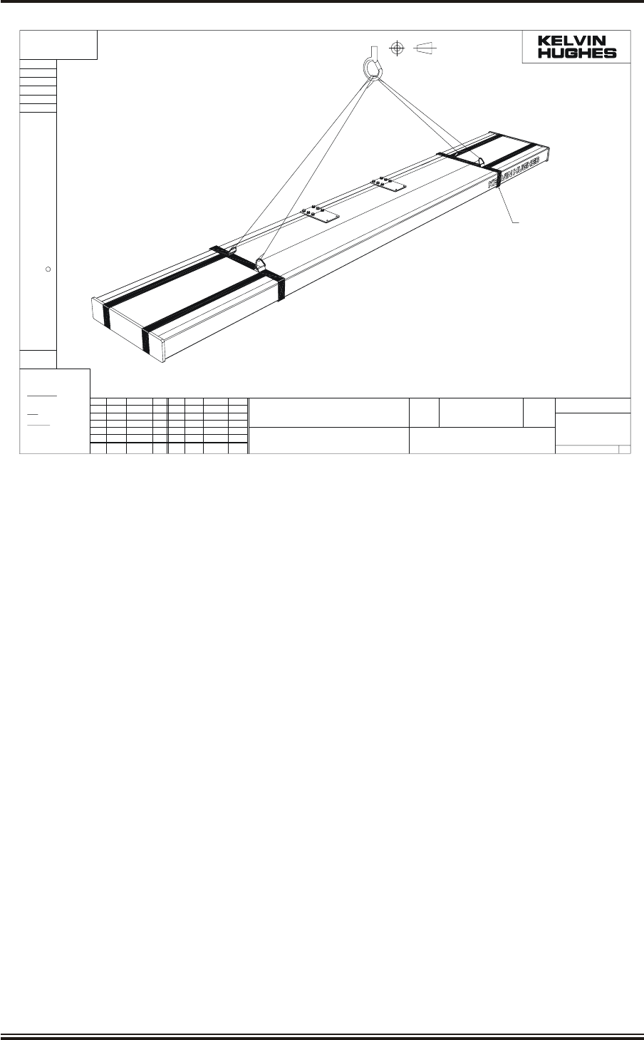
KH1264
Chap ter 4
Page 4.12 Is sue 2
±1°
CLASS H13
CLASS 6g
CLASS 6H
BS 3643
SMITHS INDUSTRIES PUBLIC LIMITED COMPANY. IT IS TO BE TREATED AS CONFIDENTIAL
C KELVIN HUGHES LIMITED
THE PREVIOUS CONSENT OF KELVIN HUGHES LTD.TO WHOM IT MUST BE RETURNED
AND MAY NOT BE REPRODUCED OR USED OR DISCLOSED TO THIRD PARTIES WITHOUT
THIS DOCUMENT IS THE PROPERTY OF KELVIN HUGHES LTD. A SUBSIDIARY OF
ANGULAR
NO DECIMAL PLACE ±1.0
ONE DECIMAL PLACE ±0.5
TWO DECIMAL PLACES ±0.15
DIMENSIONAL
TO BS 4500
HOLES
EXTERNAL
INTERNAL
COARSE PITCH
SCREW THREADS
OTHERWISE STATED
TOLERANCES UNLESS
DRAWING PRACTICE TO BS 308
PROJECTION
THIRD ANGLE
OTHERWISE STATED)
MILLIMETRES (UNLESS
ALL DIMENSIONS IN
C/NOTE
C/NOTE
SIG.DATEISSISS DATE
USED ON
DRAWN
CODE No
FINISH
MATERIAL
TITLE
M/C SCALE
CODE No.
SIMILAR TO
ISS SIG.
DEA/A3_FORMAT_ISS.3
NRDDR0458
14-06-04
1
NRD
2004
LPA-1097
NTS
LPA RECOMMENDED
LIFTING TECHNIQUE
LPA-1097
SHEET 1 OF 1 A3
DO NOT SCALE
NOTES
1.ANTENNA WEIGHT = 70 Kg
2.ENSURE LIFTING STRAPS CAN NOT FREE
RUN THRO' LIFTING HOOK.
3.ENSURE THAT LIFTING STRAP CAN NOT
RUN FREE THRO' LIFTING STRAPS LPA-1052
SEE NOTE 2
LPA-1052
SEE NOTE 3
IN 2 POS'NS
Figure 4 - Suggested Antenna Lifting Arrangement
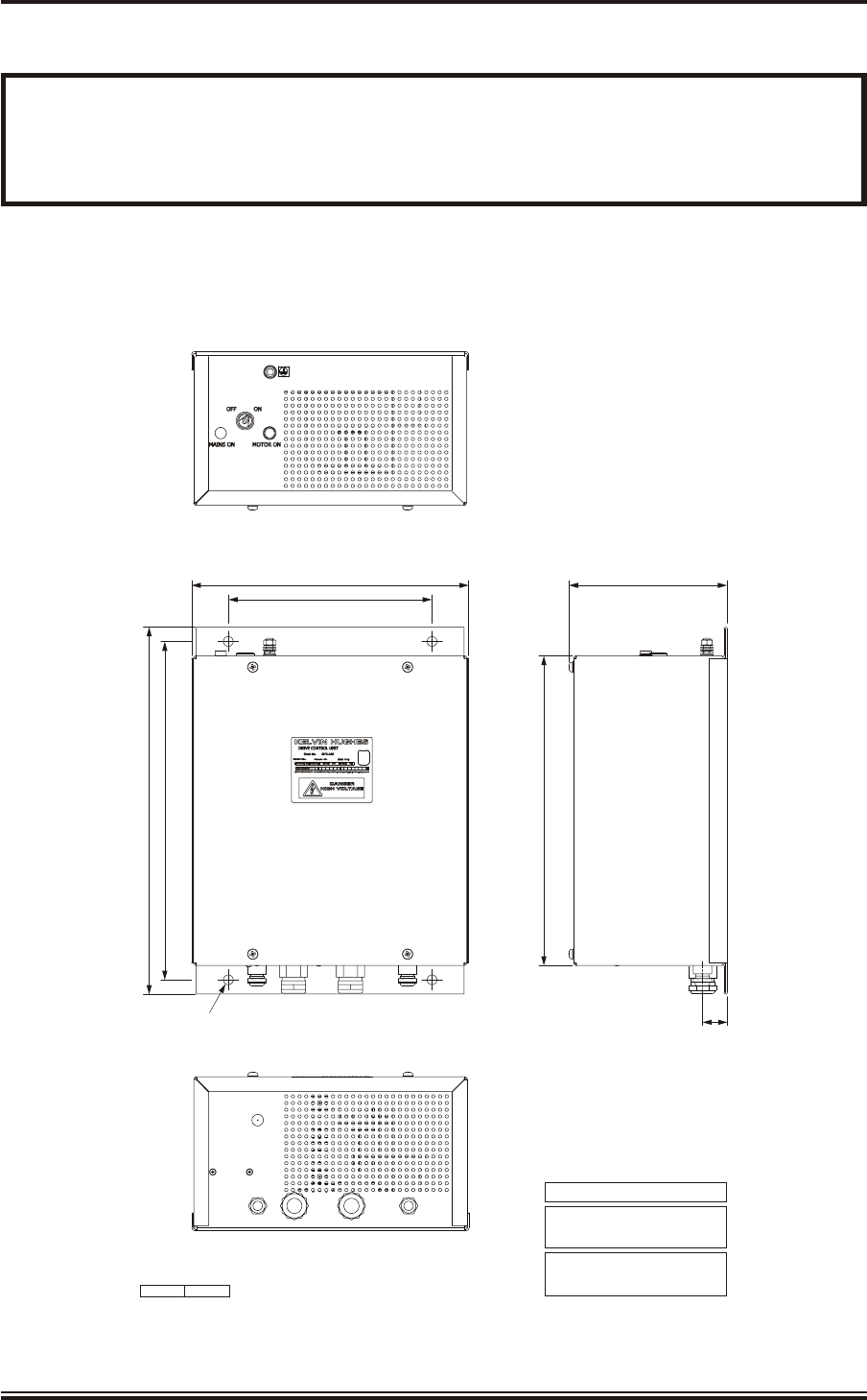
DRIVE CON TROL UNIT (GTX-A24)
WARNING
ENSURE THAT ALL POWER SUPPLIES IN THE VICINITY OF THE DRIVE
CONTROL UNIT ARE ISOLATED BEFORE ANY INSTALLATION TAKES
PLACE.
30 Fit the drive control unit to the securing bulkhead using the installation bolts supplied
with the fitting kit. Refer to Figure 5 for dimensions. Allow sufficient space at the base of
the unit to allow the cables to be inserted through the cable glands and at the top of the unit for
withdrawal of the key from the keyswitch.
KH1264
Chap ter 4
Is sue 2 Page 4.13
Ø12 FIXING HOLE
4 POSITIONS
450
415 (FIXING CENTRES)
380
340
250 (FIXING CENTRES)
30.5
CD-7022 ISSUE 3
ALL DIMENSIONS IN MILLIMETRES UNLESS OTHERWISE STATED
WEIGHT: 11kg
COMPASS SAFE DISTANCES:
OPERATIONAL TEMPERATURE RANGE:
AT 0% RELATIVE HUMIDITY -15°C to +55°C
AT 95% RELATIVE HUMIDITY +40°C
GRADE I STANDARD COMPASS 2.46m
GRADE II STEERING COMPASS 1.54m
194
Figure 5 - Drive Control Unit (GTX-A24): Installation Dimensions
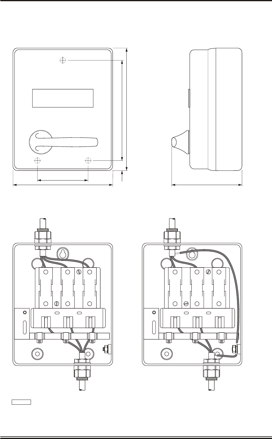
OP TIONAL MAINS ISO LA TOR (80-261-600)
31 With reference to Figure 6, secure the Mains Isolator in the required position (no fittings
are supplied).
KH1264
Chap ter 4
Page 4.14 Is sue 2
L1 L2 L3 L1 L2
L1 L2 L3
L3
L1 L2 L3
WIRING FOR 3 PHASE WIRING FOR SINGLE PHASE
CABLE
211K
15mm 1.D
CABLE GLAND
15mm 1.D
CABLE GLAND
15mm 1.D
CABLE GLAND 15mm 1.D
CABLE GLAND
CONNECT
SCREENS
TO EARTH
FIT 20 AMP FUSES FIT 20 AMP FUSES
SHIP'S SUPPLY
SINGLE PHASE
110V/220V
80
160 120
30 160
205
CD-1157
Figure 6 - Mains Isolator: Installation Dimensions

ELEC TRI CAL CON NEC TION
CA BLE SPEC I FI CA TIONS
32 Each cable is identified by a letter code which defines the type of cable required, e.g.
Cable code H is a 14-core cable. Table 1 provides specifications for each cable type.
Table 2 provides 14-core cable, colour code abbreviations.
33 The cables used to connect Kelvin Hughes equipment are to be to the following
specification. Failure to use the correct specification cables may result in impaired
equipment performance.
TABLE 1: Cable Specification
CABLE DESCRIPTION CODE CORE DIAMETER
A2-core small multi-core 1344-718 0.5 mm 6.1 mm 6.9 mm
B3-core small multi-core 1344-719 0.5 mm 6.4 mm 7.2 mm
C4-core small multi-core 1344-720 0.5 mm 6.9 mm 7.7 mm
D6-core small multi-core 1344-721 0.5 mm 7.9 mm 8.7 mm
E12-core small multi-core 1344-722 0.5 mm 10 mm 11 mm
F Not used
G Not used
H 14-core composite 45-762-0116-001 Mixed 18 mm
I 2 x 1.5 mm Power (low) 45-762-0173-001 1.5 mm 8 mm
J Not used
K 2-core Power 5344-787 2.5 mm 12 mm
L 3-core Power 5344-788 2.5 mm 13 mm
N Not used
R Not used
KH1264
Chap ter 4
Is sue 2 Page 4.15

14 Core Com pos ite Ca ble
34 The 14-core composite cable (KH code number 45-762-0116-001) is a Low Smoke and
Fume cable, but not Zero Halogen, made for Kelvin Hughes and comprises the
following:
(1) Core function:
4 cores of 32/0.2 mm (1.0 mm2) copper wire.
1 screened twisted pair 16/0.2 mm (0.5 mm2) copper wire for serial data links.
3 twisted pairs in 1 screen 16/0.2 mm (0.5 mm2) copper wire for serial data
links.
2 cores of co-axial cable 7/0.25 mm (0.35 mm2).
(2) Overall Screen
The cable has an overall screen of close woven copper braid (tinned copper
91% minimum coverage) suitable for a high noise environment.
(3) Outer Sheath
The cable has a black outer sheath to withstand exposure to the outside
environment, of salt air, rain, lubricating or diesel oil splashes, sun, snow, ice
and some possible abrasion. The outer sheath is UV stable.
(4) Conductor rating:
1.0 mm20.5 mm2Coaxial
DC between conductors 100 V 30 V 15 V
DC current 100 mA 50 mA
Impedance 75 W
Losses <3 dB at 25 MHz
up to 60 m
TABLE 2: 14-Core Cable Colour Abbreviations
ABBREVIATION COLOUR
RRED
B BLUE
GGREEN
YYELLOW
BN BROWN
VVIOLET
OORANGE
WWHITE
SSLATE (GREY)
KH1264
Chap ter 4
Page 4.16 Is sue 2

Small Multi-Core Ca bles
35 These cables conform to DEF STAN 61-12 (part 5). Each cable consists of a number of
insulated cores, collectively screened and clad in a PVC outer sheath.
36 Core Details
(1) The core details are as follows:
Conductors consist of 16 strands of 0.2 mm diameter tinned copper wire.
Nominal cross-section area of conductor = 0.5 mm2.
Nominal diameter of conductor = 0.93 mm
Nominal thickness of insulation = 0.45 mm
Minimum thickness of insulation = 0.40 mm
Minimum diameter of core = 1.75 mm
Maximum diameter of core = 1.90 mm
(2) Braided Screen
The cores are laid-up, covered with binding tape over which is woven a
braiding of 0.2 mm diameter tinned copper wire.
(3) Outer Sheath
A PVC outer sheath is applied by extrusion over the wire braiding.
(4) Maximum Current Rating
The maximum current ratings are as follows:
2.5 A at 1000 V DC
2.5 A at 440 V AC at 1600 Hz.
Power Ca bles
37 These cables are used for services requiring a moderate current carrying capacity, i.e.
main supplies.
2-Core (Power):
Cable Code K: KH Reference No. 5344-787
250/440 V grade: 7 x 0.67 mm (7 x 0.026") cores
cross linked polythene insulation,
braided with 0.2 mm (0.0078") diameter
tinned copper wire, 79% coverage
low smoke, zero halogen outer sheath.
Outer diameter: 12 mm (0.39 in.).
3-Core (Power):
Cable Code L: KH Reference No. 5344-788
(250/440 V grade): Specification as for 2-core cable.
Outer Diameter: 13 mm (0.44 in.)
KH1264
Chap ter 4
Is sue 2 Page 4.17

GEN ERAL
38 Before starting electrical connection observe the following:
WARNING
EN SURE THAT ALL POWER SUP PLIES ARE ISO LATED BE FORE ANY
ELEC TRI CAL CON NEC TION TAKES PLACE.
39 Isolate power supplies as follows:
(1) Ensure that the associated display is turned off.
(2) Remove fuses from mains isolators.
40 The casing of the upmast transceiver must be securely earthed to the platform with
braided copper wire.
41 Allow sufficient length on all cables to allow for routing through the transceiver. Make
sure that there is sufficient slack to allow for extreme movements during sudden shock to
the vessel.
42 Ensure that all cables are secured to their associated entry point and that screened cables
are earthed to their respected units.
43 Fit cable through gland in accordance with the diagram shown on Figure 9.
COVER RE MOVAL
44 Before any electrical connections can be made, covers have to be removed from the
following equipment:
(1) Upmast Transceiver.
(2) Drive Control Unit.
(3) Optional Mains Isolator.
Upmast Trans ceiver (DTX-A3)
45 Using a 12 mm spanner, release the seven bolts securing the side cover to the Upmast
Transceiver and remove the cover. Note that the cover is attached to the enclosure by a
strap to prevent it from being dropped. Cable routing is shown in Figure 7.
Drive Con trol Unit (GTX-A24)
46 Remove the Drive Control Unit cover by releasing the four fixing screws. Cable routing
is shown in Figure 8.
Op tional Mains Iso la tor (80-261-600)
47 Open the Mains Isolator cover by releasing the captive screw.
KH1264
Chap ter 4
Page 4.18 Is sue 2
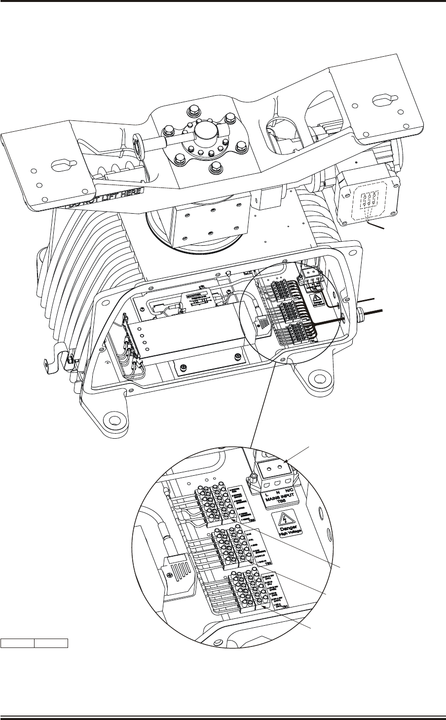
KH1264
Chap ter 4
Is sue 2 Page 4.19
CD-7030 ISSUE 3
3-CORE POWER
CABLE CODE L
(CONNECTIONS
BEHIND COVER)
2-CORE POWER
CABLE CODE K
14-CORE COMPOSITE
CABLE CODE H
TB5
TB3
TB2
TB1
Figure 7 - Transceiver (DTX-A3): Cableform Routing
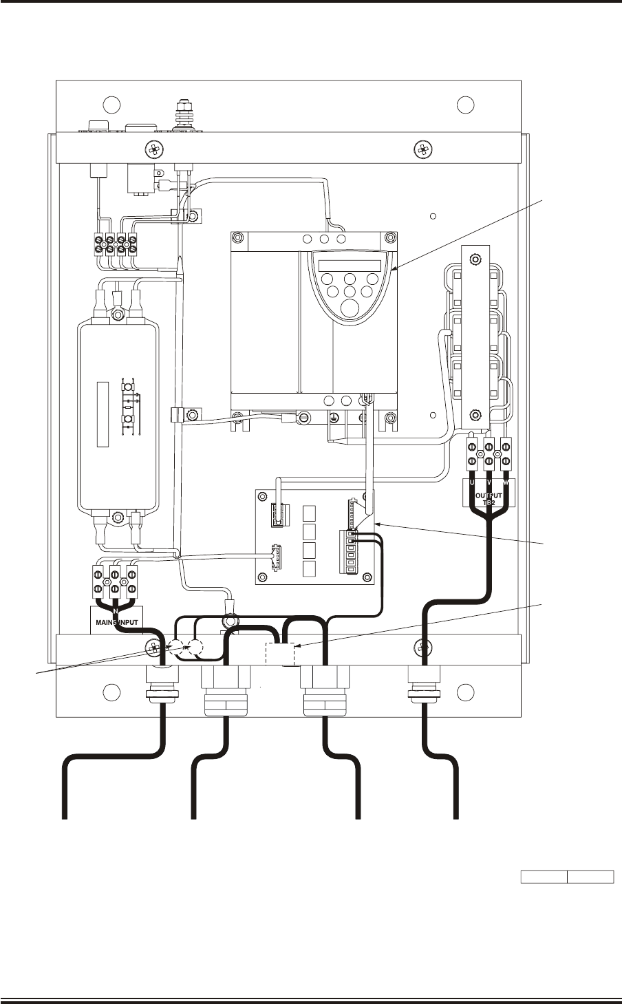
KH1264
Chap ter 4
Page 4.20 Is sue 2
CD-7024 ISSUE 4
TOSHIBA
PRG RUN RUN
MON
ENT STOP
E R/L1 S/L2
UT/1 VT/2 W/T
INVERTER
1-PHASE MAINS IN
2 CORE CABLE TYPE K
14 CORE CABLE TYPE H 3-PHASE OUT
3 CORE CABLE TYPE L
L E
PLA
DRIVE
INTERFACE PCB
SCHAFFNER
FN2070M-12-06
P
N
E
P
N
1
6
TB1
14 CORE CABLE TYPE H
1TB4
12 WAY TAGBLOCK
COAXES
Figure 8 - Drive Control Unit (GTX-A24): Cableform Routing
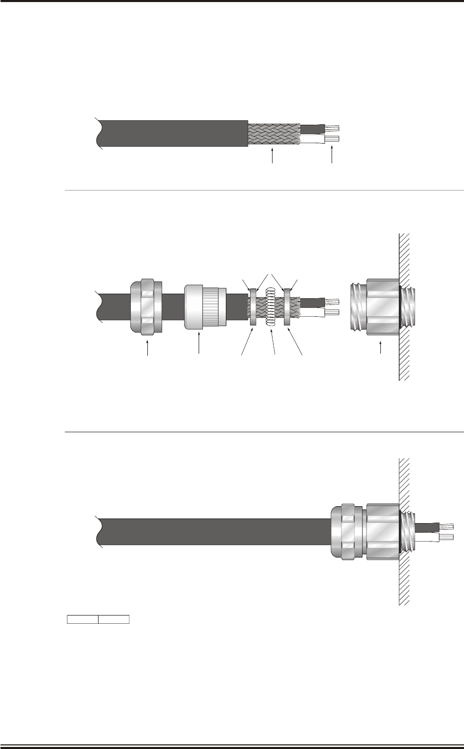
KH1264
Chap ter 4
Is sue 2 Page 4.21
RECESSED
SIDE (TO ALLOW
FOR SPRING)
FLAT
SIDE
FLAT
SIDE
PREPARE CABLE
(LENGTHS OF CORES AND SCREEN TO BE CUT TO SUIT APPLICATION)
ASSEMBLE GLAND AS SHOWN
ASSEMBLED GLAND
UNIT CASING
PRESSURE
SCREW
SEALING
INSERT
RECESSED
WASHER
RECESSED
WASHER
CIRCULAR
SPRING
GLAND
BODY
CD-7028 ISSUE 1
BRAIDED SCREEN CABLE CORES
THE BRAIDED SCREEN IS BONDED BY A CIRCULAR SPRING BETWEEN THE TWO RECESSED WASHERS.
THE CABLE GLAND’S SEALING INSERT PRESSES ON THE WASHERS. WHEN THE PRESSURE SCREW
IS TIGHTENED UP IT COMPRESSES THE SPRING TIGHTLY AROUND THE SCREEN;
AT THE SAME TIME THE SEALING INSERT BONDS THE SCREW WITH THE GLAND BODY.
NOTE:
Figure 9 - Cable Gland: Assembly

WIR ING DI A GRAMS
48 Electrical connections for upmast and downmast transceiver systems are detailed on the
wiring diagram (Figure 10). For full details of connections to the display system refer to
your system manual (KH2020, KH2026 and KH2061), as appropriate.
49 The inverter in the Drive Control Unit must be set to produce either low speed or high
speed antenna rotation to meet the operational requirements of the system. To set the
inverter to produce low speed or high speed antenna rotation, at the Drive Control Unit, Drive
Control PCB (GTX-A104) PLA, make the following connections:
Low speed (22 RPM) Link PLA pins 2 and 4 only
High speed (44 RPM): Link PLA pins 2 and 4 and
PLA pins 3 and 4
CHECKS AFTER FITTING
50 The upmast transceiver must be checked for security and freedom to rotate.
51 Ensure that all cables are secured to their associated entry point and that screened cables
are earthed to their respective units.
52 All cable entries must be checked for signs of fretting, chafing or damage, and
subsequently sealed with a mastic compound.
53 Commissioning instructions are provided in Chapter 5.
KH1264
Chap ter 4
Page 4.22 Is sue 2
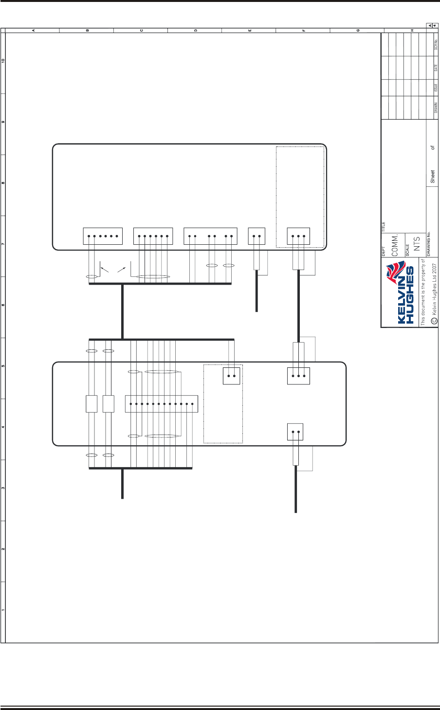
KH1262
Chap ter 4
Is sue 2 Page 4.23
L
N
U
V
W
R
B
SCR
R
Y
B
SCR
DRIVE CONTROLUNIT
GTX-A24
1
2
TB1TB2
1
2
3
2-COREPOWER
CABLE K
220V15A50/60Hz1PHASE
(100mAEARTHLEAKAGE)
NOTE:
ONDRIVE CONTROLUNIT, MAKE LINKS
ONPLA OFGTX-A104 AS FOLLOWS:
LOW SPEED:PLA-2 to PLA-4
HIGHSPEED: PLA-2 to PLA-4
&PLA-3 to PLA-4
1TB4
COAX
COAX
8
4
10
11
12
O
Bn
COAXES
W
S
TO PROCESSOR
or INTERSWITCH
Y
G
CUSTOM
CABLE H
14-CORE
CUSTOMCABLEH
14-CORE
O
Bn
COAXES
W
S
ON/OFF
COMMON
123
W
S
W
S
CAN HI
CAN LO
HL
AZ1
VIDEO 1
SYNC1
SCR
SCR
SCR
SCR
Bn/W
B/O
V
V/W
Bn/W
B/O
V
V/W
nAZ1
nHL
AZ2
nAZ2
9
5
6
7
MOTORSTART+27V
MOTORSTARTRTN
1
2
R
B
PART OFPLA
GTX-A104VIDEO
VIDEO (SCREEN)
SYNC
SYNC(SCREEN)
MOTORSTART +27V
MOTORST
ART RTN
R
Y
B
SCR
L
N
CAN HI
CAN LO
0V
GND
HL
AZ
TRANSCEIVER/GEARBOX
DTX-A3
TB2
TB3
1
2
3
4
5
6
U
V
W
TB5
1
2
5
6
1
2
3
4
MOTORLINKSMUST
BESET FOR220V
TO MOTOR
3-COREPOWER
CABLE LNOTE:
AEMOTOR
3-PHASE
2-COREPOWER
CABLEI
50/60Hz,
110V/220V/1 PHASE
W
S(W)
SCR
R
B
W
S
COAXES
123456
V
/W
O
B/O
V/W
Bn
Bn
TB1
AZ2
nAZ2
AZ1
nAZ1
HL
nHL
SCR
SCR
SCREEN NOT
TERMINATED
KELVIN HUGHES
07.12.07
1
S.R.
1
1
SharpEyeX-Band
UpmastConnections
EHD-0411-
17.01.08
2
G.S.-
02.10.08
3
G.S.-
Figure 10 - Transceiver (DTX-A3): External Connections

THIS PAGE INTENTIONALLY BLANK
KH1264
Chap ter 4
Page 4.24 Is sue 2


THIS PAGE INTENTIONALLY BLANK
KH1264
Chap ter 5
Page 5.2Is sue 2

CHAPTER 5
COMMISSIONING
IN TRO DUC TION
1Interswitched equipments, or equipments interfaced with other radar equipments, are
described in their respective Handbooks.
POWER SUP PLIES
2Check that all cables have been installed and connected.
SET TING TO WORK
WARNING
WHEN WORKING ON THE UPMAST TRANSCEIVER ALWAYS ENSURE THE
ON/OFF SWITCH ON THE DRIVE CONTROL UNIT IS SET TO OFF AND THE
KEY IS WITHDRAWN. THE KEY SHOULD BE RETAINED BY THE
INSTALLER WHEN WORKING ALOFT. REMOVAL OF THE KEY PREVENTS
THE ANTENNA FROM ROTATING.
3Carry out the following:
(1) Switch on the single phase mains at the Isolators for the Display and Transceiver.
(2) Set the Drive Control Unit switch to OFF. Ensure the switch IS NOT set to ON.
(3) Set the display power switch to ON.
4At the display ensure that the Transceiver is entered as SharpEyeTM in the installed
equipment parameters. The following parameters are set up from the display system,
refer to your system manual (KH2020, KH2026 and KH2061), as appropriate, for details of
accessing these menus:
(1) Operating Frequency. SharpEyeTM contains 14 pre-set transmission frequencies
within the operating frequency band.
(2) Reverse Sweep Mode. To minimise in-band asynchronous interference from
other X-Band SharpEyeTM radars in the same locality, the operator is able to
select a reverse sweep mode.
(3) Transmit Inhibit Sector. The SharpEyeTM radar provides one blanking sector
that is configured via the Display. Within the blanking sector, the SharpEyeTM
radar does not transmit RF energy.
KH1264
Chap ter 5
Is sue 2 Page 5.3

Drive Con trol Unit
NOTE: The inverter is set up in the factory for operation with an input frequency of 50 Hz.
WARNING
THE INVERTER MUST BE SET TO REMOTE OPERATION.
IF THE INVERTER IS SET TO LOCAL OPERATION IT WILL BE SWITCHED
ON REGARDLESS OF THE POSITION OF THE ON/OFF KEYSWITCH, THUS
OVERRIDING THE MAN ALOFT INTERLOCK FUNCTION.
5The Drive Control Unit contains an inverter that must be programmed to provide the
correct frequency of rotation for the antenna. Refer to Figure 1 for the location of the
inverter.
6Remove the Drive Control Unit front cover by releasing the four screws. This allows
access to the inverter.
7The inverter in the Drive Control Unit is Factory set for 50 Hz input and provides a 25 Hz
(low speed antenna) or 50 Hz (high speed antenna) depending on the link settings. If a
different mains frequency is used or a system specific configuration is required, the inverter may
require reconfiguring. To change a parameter proceed as follows:
NOTE: The inverter must be set up as specified in the table overleaf in order for it to function
correctly for this system. The following procedure explains how to access the menu
functions.
(1) Switch the mains ON and turn the keyswitch to the ON position. The inverter
initialises and the readout goes to 0.00.
(2) Press the MON button. Whilst programming the PRG indicator is lit for the main
function path, and flashes for F--- setting path.
(3) Press the Ý button to scroll down through the function menu as listed below. Press
the ß button to scroll up through the menu.
(4) At any function, pres ENT to read the Function Setting. Press Ý or ß to change the
setting and then press ENT to save the new setting and return to the function
menu.
(5) When the menu reaches F---, press ENT to access F100, then press Ý to scroll
F101, F102 to F990. Pressing ß scrolls F100, F990, F880 to F100.
(6) At any F--- function press ENT to read the Function Setting and Ý ß buttons to
change the Setting.
(7) Press ENT to enter the new setting and return to the Function menu.
(8) To exit menus, press MON button until 00 is displayed.
(9) To change from 50 Hz to 60 Hz operation select function typ and select 2.
(10) To set the antenna motor to high speed rotation select function 417 and set to 2820
for 50 Hz operation or 3384 for 60 Hz operation.
KH1264
Chap ter 5
Page 5.4Is sue 2

WARNING
IF OPERATION FROM THE INVERTER FRONT PANEL IS SELECTED, THE
MAN ALOFT SAFETY KEYSWITCH IS OVERRIDDEN. NEVER SELECT
OPERATION FROM THE INVERTER FRONT PANEL FOR NORMAL
OPERATIONAL USE.
(11) To select operation from the inverter front panel set function CN0d to 1
(Start/Stop local control) and FN0d to 1 (Frequency set by Ý ß). Set both
functions to 0 to return to remote control (normal operation).
8The parameters are set as follows (set for 50 Hz operation in the factory):
FUNCTION DESCRIPTION SET OPERATION
AUH HISTORY FUNCTION
AUF WIZARD FUNCTION
CN0d COMMAND MODE 0TERMINAL BLOCK
FN0d FREQUENCY SETTING MODE 0TERMINAL BLOCK
FNSL FM/OUT TERMINAL FUNCTION
SELECTION
0DEFAULT NOT USED
FN METER ADJUSTMENT 0
typ STANDARD SETTING MODE 1--0
2--0
3--0
50 Hz, sets FH, UL, uL & F170 to 50
60 Hz, sets FH, UL, uL & F170 to 60
FACTORY DEFAULT
FR FORWARD/REVERSE 0FORWARD
ACC ACCELERATION TIME 2SECONDS
dEC DECELERATION TIME 10 SECONDS
FH MAXIMUM FREQUENCY 50/60 50 Hz or 60 Hz (set by typ)
UL UPPER LIMIT FREQUENCY 50/60 50 Hz or 60 Hz (set by typ)
LL LOWER LIMIT FREQUENCY 00 Hz
uL BASE FREQUENCY (MOTOR) 50/60 50 Hz or 60 Hz (set by typ)
Pt V/F CONTROL MODE SELECTION 0VOLTAGE/FREQUENCY CONSTANT
ub TORQUE BOOST 55% BOOST
tHr MOTOR THERMAL PROTECTION LEVEL 80 80% (EQUIVALENT 1.5 kW MOTOR)
0LN ELECTRONIC THERMAL PROTECTION
LEVEL
0OVERLOAD PROTECTION OFF
OVERLOAD STALL ON
Sr-1 PRESET SPEED FREQUENCY 1 00 Hz
Sr-2 PRESET SPEED FREQUENCY 2 25 25 Hz
Sr-3 PRESET SPEED FREQUENCY 3 50 50 Hz
Sr-4 PRESET SPEED FREQUENCY 4 00 Hz
Sr-5 PRESET SPEED FREQUENCY 5 00 Hz
Sr-6 PRESET SPEED FREQUENCY 6 00 Hz
Sr-7 PRESET SPEED FREQUENCY 7 00 Hz
F— EXTENDED PARAMETER ENT
F109 ANALOG/LOGIC INPUT FUNCTION
SELECT
2CONTACT INPUT
F127 SINK/SOURCE INPUT SELECTION 100 SOURCE
F170 BASE FREQUENCY 2 50/60 50 Hz or 60 Hz (set by typ)
F300 PWM CARRIER FREQUENCY 2 4 kHz
F301 AUTO RESTART 0DISABLED
F302 REPETITIVE POWER RIDE-THROUGH 0DISABLED
F303 RETRY SELECTION
F417 MOTOR SPEED 2820
3384
For 50 Hz
For 60 Hz
Gr..U SEARCH FOR CHANGED SETTINGS
THIS MENU ONLY SHOWS PARAMETERS
THAT ARE NOT SET TO DEFAULT VALUE.
GIVES FAST TRACK THROUGH MENUS.
KH1264
Chap ter 5
Is sue 2 Page 5.5

Trans ceiver Checks
NOTE: The following checks require the display to be configured for the transceiver/antenna
combination.
9Set any Mains Isolators to ON.
10 At the Drive Control Unit, insert the key into the ON/OFF keyswitch and set the switch to
ON.
11 Configure the display for the transceiver/antenna combination installed.
12 Verify that the display indicates TX READY after the warm up period of approximately
30 seconds. Check that no fault indications are displayed.
13 Ensure that the antenna is rotating.
14 At the display set the transceiver to RUN.
15 Check that a radar picture is displayed on the screen, and no failure messages are
displayed.
16 Confirm that known targets are being tracked on the display.
KH1262
Chap ter 5
Page 5.6Is sue 2
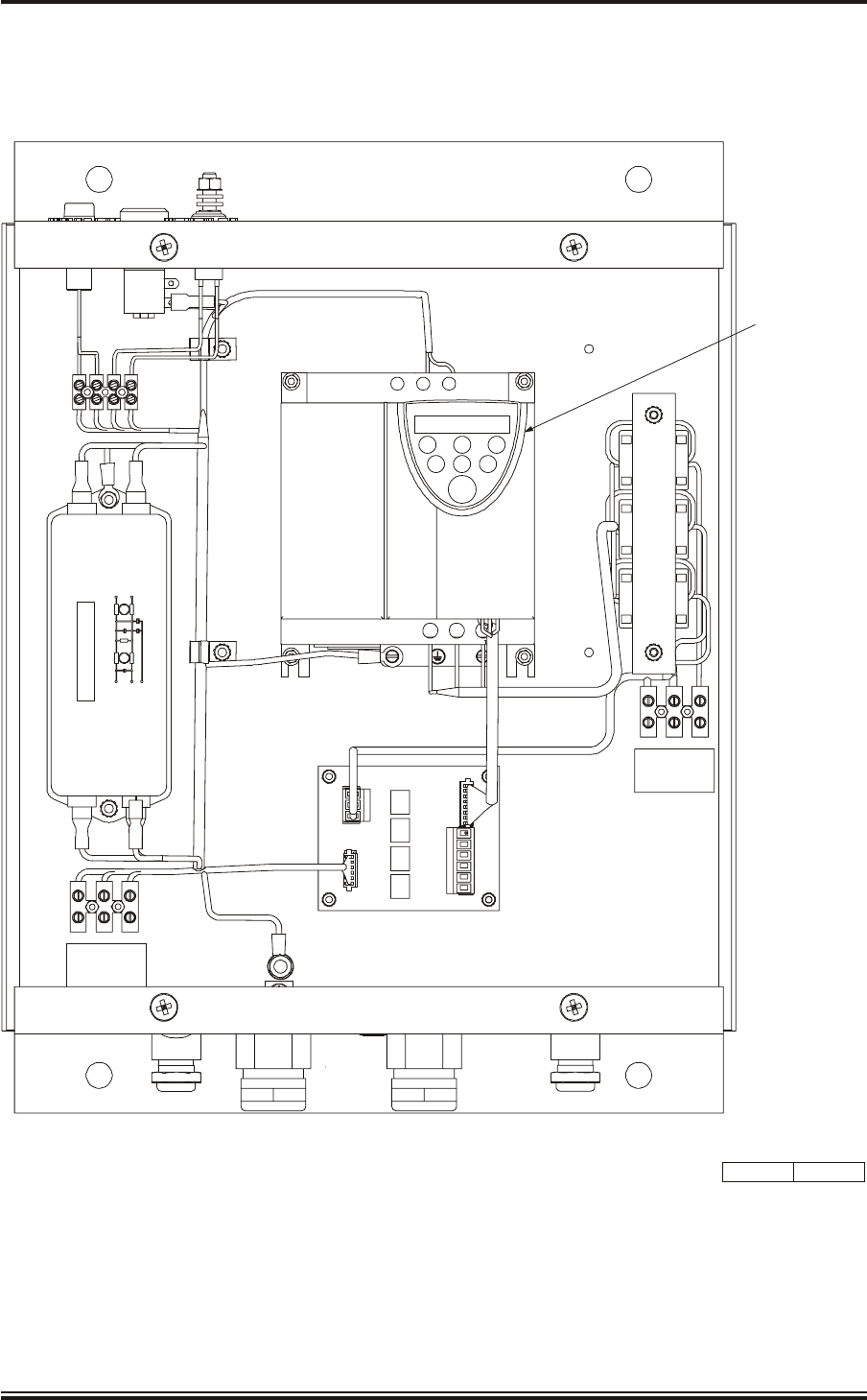
KH1264
Chap ter 5
Is sue 2 Page 5.7
TB2
OUTPUT
MAINS INPUT
TB1
CD-7023 ISSUE 3
TOSHIBA
PRG RUN RUN
MON
ENT STOP
E R/L1 S/L2
UT/1 VT/2 W/T
INVERTER
L N E
U V W
PLA
SCHAFFNER
FN2070M-12-06
P
N
E
P
N
Figure 1 - Drive Control Unit: Inverter Location

THIS PAGE INTENTIONALLY BLANK
KH1264
Chap ter 5
Page 5.8Is sue 2

CHAPTER 6
MAINTENANCE
CON TENTS
Paragraph Page
KH1264
Chap ter 6
Is sue 2 Page 6.1
1IN TRO DUC TION 6.3
2PLANNED MAINTENANCE 6.3
2SIX MONTHLY CHECKS 6.3
2An tenna 6.3
3Trans ceiver Cas ing In spec tion 6.3
4DI AG NOS TIC MAIN TE NANCE 6.4
5PRE-REQ UI SITES 6.4
6FAIL URE MES SAGES 6.4
9TEST EQUIP MENT 6.5
10 PREP A RA TION FOR FAULT DI AG NO SIS 6.5
11 IN DI CA TORS 6.6
12 COR REC TIVE MAIN TE NANCE 6.11
13 TRANS CEIVER (DTX-A3) 6.12
14 Access 6.12
15 Re moval of Ro tat ing Joint (45-750-0034-001) 6.12
16 Re place ment of Ro tat ing Joint (45-750-0034-001) 6.13
17 Re moval of Gear box and Mo tor (55-100-0273-001) 6.13
18 Re place ment of Gear box and Mo tor (55-100-0273-001) 6.13
19 Re moval of Az i muth En coder (GTX-A188) 6.13
20 Re place ment of Az i muth En coder (GTX-A188) 6.13
21 Trans ceiver (DTX-A115) - Re moval 6.14
22 Trans ceiver (DTX-A115) - Replacement 6.14
23 Power Sup ply (45-690-0062-002) and PSU Sense PCB (DTX-A121) - Removal 6.15
25 Power Sup ply (45-690-0062-002) and PSU Sense PCB (DTX-A121) - Re place ment 6.15
26 CAN Adapter PCB (NNR-A981) - Re moval 6.15
27 CAN Adapter PCB (NNR-A981) - Re place ment 6.15
28 SharpEye Az i muth In ter face PCB (DTX-A151) - Re moval 6.16
29 SharpEye Az i muth In ter face PCB (DTX-A151) - Re place ment 6.16
30 DRIVE CON TROL UNIT (GTX-A24) 6.18
31 Ac cess 6.18
32 In verter As sem bly - Removal 6.18
33 In verter As sem bly - Replacement 6.18
34 Drive In ter face PCB (GTX-A104) - Removal 6.18
35 Drive Interface PCB (GTX-A104) - Replacement 6.18
36 Mains Fil ter (45-680-0028-01) - Re moval 6.18
37 Mains Fil ter (45-680-0028-01) - Re place ment 6.19
38 CHECKS AF TER UNIT RE PLACE MENT 6.20
40 Trans ceiver 6.20
41 Drive Con trol Unit 6.20


CHAPTER 6
MAINTENANCE
IN TRO DUC TION
1This Chapter is divided into three parts:
(1) Planned Maintenance.
(2) Diagnostic Maintenance.
(3) Corrective Maintenance.
PLANNED MAINTENANCE
NOTE: The transceiver runs continuously runs performance checks in the background, and any
degradation in performance is reported as a warning message. There are no routine
operator or maintainer performance checks required on the transceiver.
SIX MONTHLY CHECKS
NOTE: If you detect any problems when carrying out the following routine maintenance
procedures contact the Kelvin Hughes Service Control Centre or your agent for advice.
CAUTION
Always switch the radar OFF, and as an additional precaution, switch OFF the
antenna safety switches when working on the transceiver or antenna.
An tenna
2Visually check the front radiating window for damage and soot or dirt. Note that even a
thin layer of soot or dirt can cause serious loss of radar performance. If necessary,
CAREFULLY wipe the antenna front radiating window using soap and water and a soft
non-abrasive cloth. Ensure the window is not scratched or damaged when carrying out this
procedure.
CAUTION
NEVER PAINT the front radiating window.
Trans ceiver Cas ing In spec tion
3Visually inspect that all screws, nuts and bolts are secure and free from corrosion.
KH1264
Chap ter 6
Is sue 2 Page 6.3

DI AG NOS TIC MAIN TE NANCE
WARNING
THIS EQUIP MENT IS NOT FITTED WITH SAFETY IN TER LOCKS AND
LE THAL VOLT AGES ARE PRES ENT WITHIN THE UNIT. AC CESS TO THE
IN TE RIOR OF THE UNIT IS ONLY TO BE CARRIED OUT BY A QUAL IFIED
TECH NI CIAN.
4The flowcharts in this chapter provide an aid to fault diagnosis in the transceiver. The
algorithms enable fault diagnosis down to module level and also identify wiring faults.
Entry to the algorithms is via Failure Messages generated by the display.
PRE-REQ UI SITES
5The diagnostic routines in the flow charts assume that the radar has been working, and
that the system is set up for normal operation at the time the fault occurred.
FAIL URE MES SAGES
6These failure messages appear in the data field of the display monitor if certain signals
are missing. One or more of the following messages may be displayed on the display
system:
(1) No Sync. Indicates that the display is not detecting sync pulses from the
transceiver.
(2) No Video. Indicates that the display is not detecting video from the transceiver.
(3) No Azimuth. Indicates that the display is not detecting azimuth pulses from the
transceiver.
(4) No Heading Line. Indicates that the display is not detecting heading line pulses
from the transceiver.
7The following messages are supplied from the transceiver via the CAN bus, which may
switch to degraded mode of operation (low power output, low sensitivity etc) or fault
mode:
(1) Receiver Sensitivity Low. This indicates that the minimum detectable signal is
³TBD dB, indicating a receiver fault. The transceiver continues operating in the
degraded state. Should the minimum detectable signal be ³TBD dB, the
transceiver will enter the fault state.
(2) Antenna VSWR High. The transceiver has detected a high reverse power and
hence VSWR. This indicates that there is a mismatch in the transceiver output to
the antenna, e.g. an antenna or rotating joint fault.
(3) RF Power Low. The transceiver has detected low power on the output. If the
power is 3 dB below normal this indicates that one of the two RF output
transistors in the transceiver has failed, i.e. a fault in the transceiver unit. The
transceiver continues operating in a degraded state on half power. Should the
second RF output transistor then fail, the transceiver will enter the fault state.
KH1264
Chap ter 6
Page 6.4Is sue 2

(4) PLO Lock. Indicates that the phase locked oscillator has developed a hardware
fault.
(5) Synth Lock. Indicates that the frequency synthesiser has developed a hardware
fault.
(6) Transmitter Over-temperature. This indicates that the temperature of the RF
power transistors is high, indicating a fault in the transceiver.
8Fault diagnosis algorithms covering these failures is provided in Figure 3.
TEST EQUIP MENT
9Fault location is to module replacement level only. The only test equipment required for
fault finding is a high impedance Multimeter.
PREP A RA TION FOR FAULT DI AG NO SIS
WARNING
THIS EQUIPMENT IS NOT FITTED WITH SAFETY INTERLOCKS AND
LETHAL VOLTAGES ARE PRESENT WITHIN THE UNIT. ACCESS TO THE
INTERIOR OF THE TRANSCEIVER IS ONLY TO BE CARRIED OUT BY A
QUALIFIED TECHNICIAN.
CAUTIONS
(1) Handling Of Electrostatic Sensitive Semiconductor Devices.
Semiconductor devices used in the equipment are liable to damage due
to static voltage. Observe the following precautions when handling
these devices in their unterminated state, or modules containing these
devices.
Persons removing modules from an equipment using these devices
should be earthed by a wrist strap and a resistor.
Soldering irons used during repair operations must be low voltage
types with earth tips and isolated from the mains voltage by a double
insulated transformer.
Outer clothing worn must be unable to generate static voltages.
Printed Circuit Boards (PCBs) fitted with these devices must be stored
and transported in anti-static bags.
Fit new devices in a special handling area.
For detailed information, refer to British Standard BS 5783 or other
equivalent standard.
KH1264
Chap ter 6
Is sue 2 Page 6.5

10 To access the units inside the upmast transceiver, remove the side cover of the
transceiver. This allows access to the transceiver and the power supply and allows the
LEDs on the PSU Sense PCB and CAN Adapter PCB to be seen.
WARNING
IT IS DANGEROUS TO RUN THE TRANSCEIVER WHEN UPMAST AS THE
ANTENNA IS ROTATING AND RF IS RADIATED. UNDER NO
CIRCUMSTANCES SHOULD THE MAINTAINER BE UPMAST WHEN RF IS
RADIATED AND/OR THE ANTENNA IS ROTATING. THEREFORE ALL
CHECKS MUST BE MADE WITH THE TRANSCEIVER IN STANDBY MODE,
THIS WILL LIMIT THE CHECKS THAT CAN BE MADE WHEN THE
TRANSCEIVER IS SET TO RUN.
IN DI CA TORS (Fig ure 1)
11 The indicators provided on the CAN Adapter PCB are as follows:
D4 MUTE. Unlit (not used) (Lit when mute active)
D5 RUN. Unlit (not used) (Lit when Run is active)
D11 +15 V. Lit when +15 V supply present
D12 -15 V. Lit when -15 V supply present
D13 RUNNING. Flashes when processor running
D14 LED 1. Lit when heartbeat received
D15 LED 2. Unlit (not used)
D16 +24 V. Lit when +24 V supply present
D38 +5 V. Lit when +5 V supply present
KH1264
Chap ter 6
Page 6.6Is sue 2
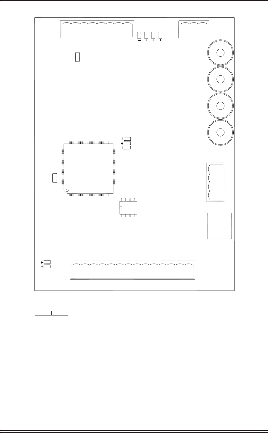
KH1264
Chap ter 6
Is sue 2 Page 6.7
VIEW ON COMPONENT SIDE
IC1
D15
D14
D13
LK2
SW1
PLB
1
D5
D4
D38
D12
D11
D16
PLA PLC
1
SKE
SKF
SKG
SKH
PLJ
1
SKD
LK1
1
CD-7423 ISSUE 1
Figure 1 - CAN Adapter PCB (NNR-A981): LED Location

THIS PAGE INTENTIONALLY BLANK
KH1264
Chap ter 6
Page 6.8Is sue 2
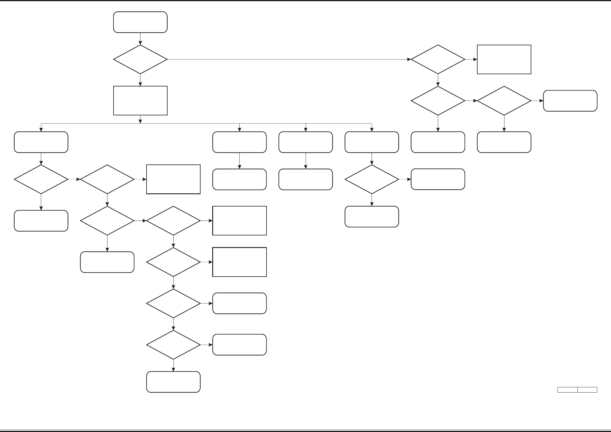
KH1264
Chap ter 6
Is sue 2 Page 6.9/10
RADAR FAULT
DETECTED AT DISPLAY
(AT STANDBY)
IS Tx READY
IND PRESENT?
SWITCH TO RUN
ON PSU SENSE PCB
ARE D2, D3 & D4 LIT?
ON CAN
ADAPTER PCB,
IS D13 FLASHING?
(PROC RUNNING
LED)
POWER SUPPLY FAULT
IS THE
ANTENNA TURNING?
FAULT IN
AZ ENCODER GTX-A188
OR CONNECTIONS THROUGH
SHARPEYE AZ
CONVERTER PCB DTX-A151
FAILURE MESSAGE
CHECK CONNECTIONS,
MAINS INPUT &
POWER SUPPLY
REPAIR CONNECTIONS
IF NECESSARY.
OTHERWISE POWER SUPPLY
OR EMC FILTER FAULT
ON CAN
ADAPTER PCB
ARE D11, D12, D16
& D38 LIT?
IS MAINS
INDICATOR ON
DRIVE CONTROL
UNIT LIT?
CHECK MAINS SUPPLY
IS MOTOR
ON LED LIT?
FAULT WITH
TRANSCEIVER DTX-A115
FAULTY WIRING TO
ANTENNA MOTOR OR
MOTOR FAULT
FAILURE MESSAGE
- NO AZIMUTH
- NO HEADING LINE
IS KEYSWITCH
SET TO ON? SET SWITCH TO ON
IS +27V PRESENT
AT PLA, PIN 1 ON DRIVE
INTERFACE PCB?
FAULT WITH
TRANSCEIVER DTX-A115
OR CONNECTION FAULT
CD-7620 ISSUE 1
YES
NO
YES
NO
YES
NO
YES
NO
YES
NO
YES
NO
NO
YES
YES
NO NO
YES
IS PLA PIN 2
LESS THAN 1V DC?
YES
NO
FAULT WITH INVERTER
(IN DRIVE CONTROL UNIT)
DOES
INVERTER DISPLAY
SHOW AN OUTPUT OF
50 OR 25?
YES
NO
FAULTY WIRING TO
ANTENNA MOTOR OR
MOTOR FAULT
FAULT ON
CAN ADAPTER PCB NNR-A981
FAULT ON
TRANCEIVER DTX-A115
- Rx SENSITIVITY LOW
- RF POWER LOW
- PLO LOCK
- SYNTH LOCK
- OVERTEMPERATURE
FAULT WITH
TRANSCEIVER DTX-A115
FAILURE MESSAGE
- ANTENNA VSWR HIGH
FAULT WITH
ANTENNA or ROTATING JOINT
FAILURE MESSAGE
- NO SYNC
- NO VIDEO
ARE COAXES OK? NO
YES
REPAIR COAXES
FAULT WITH
TRANSCEIVER DTX-A115
Figure 2 Transceiver: Fault Diagnosis Figure 2

COR REC TIVE MAIN TE NANCE
WARNING
THIS EQUIPMENT IS NOT FITTED WITH SAFETY INTERLOCKS AND
LETHAL VOLTAGES ARE PRESENT WITHIN THE UNIT. ACCESS TO THE
INTERIOR OF THE TRANSCEIVER IS ONLY TO BE CARRIED OUT BY A
QUALIFIED TECHNICIAN.
CAUTIONS
(1) Handling Of Electrostatic Sensitive Semiconductor Devices.
Semiconductor devices used in the equipment are liable to damage due
to static voltage. Observe the following precautions when handling
these devices in their unterminated state, or modules containing these
devices.
Persons removing modules from an equipment using these devices
should be earthed by a wrist strap and a resistor.
Soldering irons used during repair operations must be low voltage
types with earth tips and isolated from the mains voltage by a double
insulated transformer.
Outer clothing worn must be unable to generate static voltages.
Printed Circuit Boards (PCBs) fitted with these devices must be stored
and transported in anti-static bags.
Fit new devices in a special handling area.
For detailed information, refer to British Standard BS 5783 or other
equivalent standard.
12 When a module is to be refitted, or a new one fitted, the refitting process is in the reverse
order of the removal procedure unless stated otherwise.
KH1264
Chap ter 6
Is sue 2 Page 6.11

TRANS CEIVER (DTX-A3)
13 The locations of the modules and assemblies in the upmast transceiver and turning
mechanism are shown in Figure 3.
Access
14 Access to the modules and assemblies in the Upmast Transceiver, except the motor and
gearbox, is attained by releasing the seven bolts securing the side cover in position and
then removing the cover.
Re moval of Ro tat ing Joint (45-750-0034-001)
15 To remove the rotating joint, proceed as follows:
(1) Remove the antenna from the gearbox as follows:
CAUTION
When removing the antenna support it near its centre when lifting it from the
gearbox. Do not handle the antenna by the waveguide input.
When removing and replacing the antenna ensure the waveguide input, on the end of
the antenna, is not crushed or damaged.
(a) Slacken the 4 M8 x 75 mm bolts securing the antenna to the mounting
bracket, allowing the antenna to be moved.
(b) Remove and retain all bolts, nuts, washers and screws securing the
waveguide to the rotating joint, antenna waveguide input and mounting
bracket. Carefully withdraw the waveguide from the assembly and store in
a safe place.
(c) Remove and retain the 4 M8 x 75 mm bolts securing the antenna to the
mounting bracket, and carefully withdraw the antenna from the mounting
bracket.
(d) Remove and retain the 8 M10 x 40 mm bolts securing the mounting bracket
to the swing casting.
(2) Inside the transceiver housing remove and retain the 4 allen key socket head
screws that secure the bottom 90 degree bend of the rotating joint to the main
shaft of the rotating joint.
(3) Before withdrawing the rotating joint, it will also be necessary to untie the unused
coil of S-Band feed.
(4) Remove and retain the 6 M6 x 20 mm bolts and M6 washers that secure the top
housing of the rotating joint to the swing casting, and carefully withdraw the
rotating joint upwards out of the swing casting.
(5) If the bottom 90 degree bend of the rotating joint is also required, remove and
retain the 4 bolts, nuts and washers that secure it to the internal waveguide.
KH1264
Chap ter 6
Page 6.12 Is sue 2

Re place ment of Ro tat ing Joint (45-750-0034-001)
16 To replace the rotating joint, reverse the above procedure. Tighten and torque load the 12
antenna retaining bolts to 56 Nm and apply Loctite 222 on their threads during assembly.
Waterproof the coaxial joint to the antenna by sealing with a layer of greased plastic compound
such as Henleys compound or Denso-Tape.
Re moval of Gear box and Mo tor (55-100-0273-001)
17 To remove the gearbox, complete with motor, proceed as follows:
(1) Remove the antenna and rotating joint as described in paragraph 14.
(2) Remove and retain the six bolts securing the swing casting to the gearbox.
Remove and retain the swing casting.
(3) Using an Allen Key, remove and retain the six bolts securing the Mounting Disc
to the Gearbox and Motor. Remove and retain the Mounting Disc.
(4) Disconnect the electrical connections to the motor.
(5) Remove and retain the eight nuts securing the gearbox and motor to the enclosure
(these are located inside the enclosure under the gearbox.
(6) Lift the gearbox, complete with motor, from the casting.
Re place ment of Gear box and Mo tor (55-100-0273-001)
18 To replace the gearbox, reverse the above procedure.
Re moval of Az i muth En coder (GTX-A188)
19 To remove the azimuth encoder, proceed as follows:
(1) Unplug the rigid RF Coaxial cable from the transceiver. Remove and retain the
three bolts securing the rigid RF Coaxial cable to the rotating joint. Remove the
coaxial cable and the coupling element and retain. This allows the encoder to be
removed from the rotating joint.
(2) Unplug the Azimuth Encoder flying lead from the housing cableform (located in
the top of the housing).
(3) Remove and retain the three bolts securing the rotating joint to the RF coaxial
cable.
(4) Unscrew the flange from the base of the rotating joint.
(5) Remove and retain the two screws securing the Azimuth Encoder to the casting.
(6) Slacken the three grub screws securing the azimuth encoder to the gearbox and
carefully remove the Azimuth Encoder, ensuring the cable is not damaged.
Re place ment of Az i muth En coder (GTX-A188)
20 To replace the azimuth encoder, reverse the above procedure.
KH1262
Chap ter 6
Is sue 2 Page 6.13

Trans ceiver (DTX-A115) - Re moval
21 To remove the Transceiver, proceed as follows:
(1) Remove all power supplies to the transceiver.
NOTE: The D -type connectors have a sliding metal retainer which must be moved fully
one way before the connector can be removed. Note that the transceiver is
removed in two sections.
(2) Disconnect the internal waveguide from the transceiver by removing the four sets
of bolts and nuts. If necessary remove and retain the waveguide by releasing the
four bolts securing it to the casing.
(3) Disconnect all the internal cableforms from the transceiver, including the coaxial
cable to the rotating joint.
(4) Remove and retain the two semi-rigid cables on top of the transceiver (forward
and reverse). Remove and retain the two semirigid cables at the side of the
transceiver fitted between the upper and lower sections. Remove and retain the
multiway cable at the side of the transceiver between the upper and lower
sections. Note the position of each of the five cables.
(5) Remove the six small bolts securing the waveguide to the top of the upper section
of the transceiver, and lift the waveguide up to access the securing bolts (a section
of flexible waveguide is used to allow the waveguide to be hinged up).
(6) Remove the 15 large bolts (three rows of five bolts) securing the top section of the
transceiver to the bottom section (DO NOT release the smaller bolts). Lift the top
section clear of the unit. Note that the bolts do not go through the unit, but are
screwed into studs on the bottom section of the unit, which align the two sections
of the transceiver.
(7) Remove the 18 bolts securing the lower section of the transceiver to the side of the
casing and remove the transceiver.
Trans ceiver (DTX-A115) - Replacement
22 To replace the Transceiver reverse the above procedure. There is no setting up for this
unit.
KH1264
Chap ter 6
Page 6.14 Is sue 2

Power Sup ply (45-690-0062-002) and PSU Sense PCB (DTX-A121) - Removal
23 To remove the Power Supply, proceed as follows:
(1) Remove the connectors from the Power Supply.
(2) Release the two captive screws securing the Power Supply to the base of the case.
(3) Pull the unit out, releasing the two securing flanges securing the power supply to
the baseplate, and remove the power supply.
24 To remove the PSU Locating Plate, complete with mains filter, from the Power Supply
(Modular) Xgen series (45-690-000062-002) remove and retain the four screws securing
the PSU Locating Plate to the power supply and disconnect the cable from the mains filter.
Retain the PSU Locating Plate.
Power Sup ply (45-690-0062-002) and PSU Sense PCB (DTX-A121) - Re place ment
25 To replace the Power Supply Assembly reverse the above procedure. Ensure the two
flanges are correctly inserted into baseplate.
CAN Adapter PCB (NNR-A981) - Re moval
26 To remove the CAN Adapter PCB, proceed as follows:
(1) Remove the connectors from the CAN Adapter PCB.
(2) Remove and retain the six screws securing the CAN Adapter PCB and remove
the PCB.
CAN Adapter PCB (NNR-A981) - Re place ment
27 To replace the CAN Adapter PCB reverse the above procedure. Ensure SW1 on the
replacement PCB is set as follows:
Position 1 OFF
Position 2 OFF
Position 3 OFF
Position 4 ON
KH1264
Chap ter 6
Is sue 2 Page 6.15

SharpEye Az i muth In ter face PCB (DTX-A151) - Re moval
28 To remove the SharpEyeTM Azimuth Interface PCB, proceed as follows:
(1) Remove the connectors from the SharpEyeTM Azimuth Interface PCB.
(2) Remove and retain the two screws securing the SharpEyeTM Azimuth Interface
PCB and remove the PCB.
SharpEye Az i muth In ter face PCB (DTX-A151) - Re place ment
29 To replace the SharpEyeTM Azimuth Interface PCB reverse the above procedure.
KH1264
Chap ter 6
Page 6.16 Is sue 2
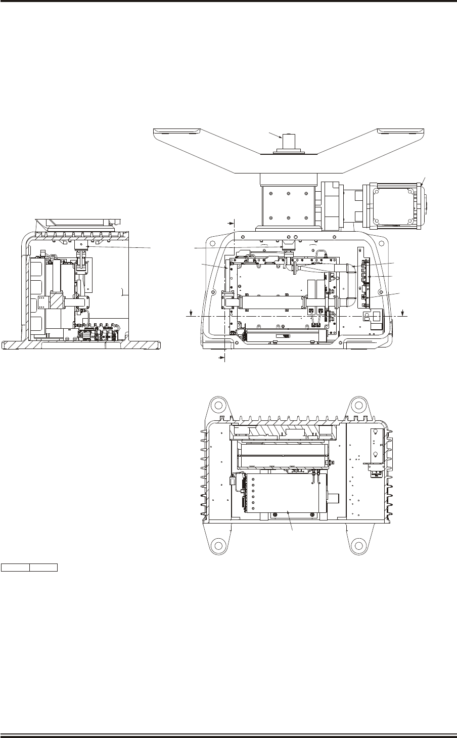
KH1264
Chap ter 6
Is sue 2 Page 6.17
SECTION ON A-A
SECTION ON B-B DOOR REMOVED FOR CLARITY
DTX-A115
KELVIN HUGHES
RADAR TRANSCEIVER
FMS090-5600
SERIAL No.
MOD:-
ISOLATE
MAINS BEFORE
SERVICING
ISOLATE
MAINS BEFORE
SERVICING
ACHACH
A
B
B
A
ENCODER AZ/HL
GTX-A188
X-BAND Tx ASSEMBLY
DTX-A115
POWER SUPPLY TYPE
XLC 503-POS A
45-690-0062-002
ROTATING JOINT
MOTOR & GEARBOX
3 PHASE
55-100-0273-001
INTERNAL
WAVEGUIDE ASSEMBLY
DTX-A170
CAN ADAPTOR PCB
NNR-A981
AZIMUTH INTERFACE PCB
DTX-A151
CD-7617 ISSUE 1
Figure 3 - Transceiver (DTX-A3): Module Locations

DRIVE CON TROL UNIT (GTX-A24)
30 The locations of the modules and assemblies in the Drive Control Unit are shown in
Figure 4.
Ac cess
31 Access to the modules and assemblies is attained by releasing the four screws securing
the cover in position and then removing the cover.
In verter As sem bly - Removal
32 To remove the Inverter Assembly, proceed as follows:
(1) Remove power from the Drive Control Unit.
(2) Remove all electrical connections from the Inverter Assembly, ensuring each
cable is identified.
(3) Remove and retain the four nuts securing the Inverter Assembly and remove.
In verter As sem bly - Replacement
33 To replace the inverter assembly reverse the above procedure. Ensure the cables are
connected correctly to the new Inverter Assembly. The new inverter assembly must be
programmed before use as described in Checks After Replacement.
Drive In ter face PCB (GTX-A104) - Removal
34 To remove the Drive Interface PCB, proceed as follows:
(1) Remove power from the Drive Control Unit.
(2) Remove the internal and external connections to the Drive Interface PCB.
(3) Remove and retain the four nuts securing the Drive Interface PCB and remove.
Drive Interface PCB (GTX-A104) - Replacement
35 To replace the Drive Interface PCB reverse the above procedure.
Mains Fil ter (45-680-0028-01) - Re moval
36 To remove the Mains Filter, proceed as follows:
(1) Remove power from the Drive Control Unit.
(2) Remove the four internal connections to the Mains Filter.
(3) Remove and retain the two nuts securing the Mains Filter and earth tag. Remove
the Mains Filter.
KH1264
Chap ter 6
Page 6.18 Is sue 2
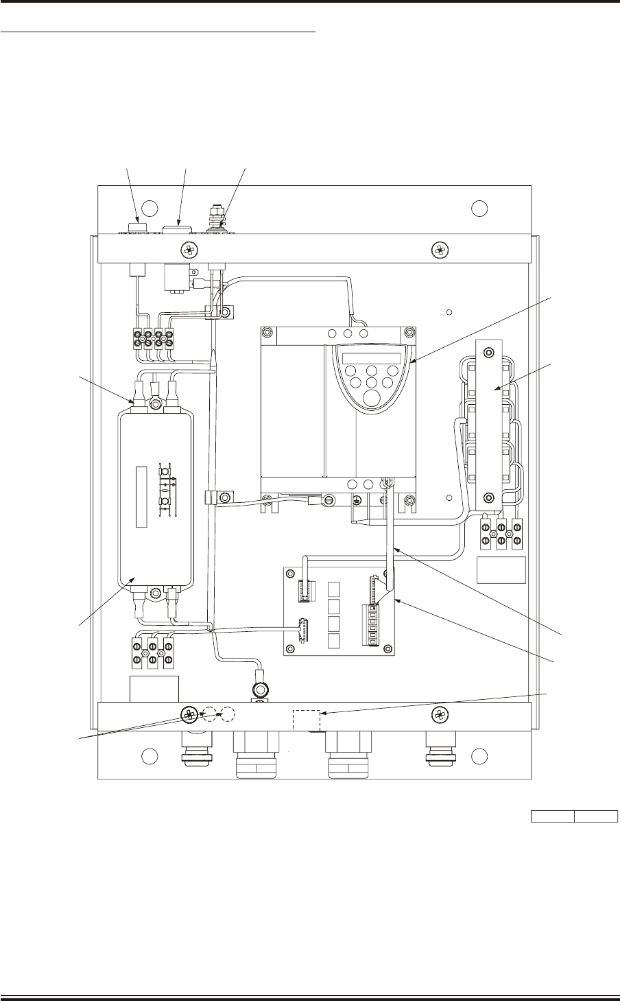
Mains Fil ter (45-680-0028-01) - Re place ment
37 To replace the Mains Filter reverse the above procedure, ensuring the earth tag is refitted
and secured.
KH1264
Chap ter 6
Is sue 2 Page 6.19
CD-7275 ISSUE 1
TOSHIBA
PRG RUN RUN
MON
ENT STOP
E R/L1 S/L2
UT/1 VT/2 W/T
INVERTER
45-690-0033-001
PLA
DRIVE
INTERFACE PCB
GTX-A104
SCHAFFNER
FN2070M-12-06
P
N
E
P
N
1
6
NEON INDICATOR GREEN
45-6000-0076-001
LED INDICATOR GREEN
45-6000-0049-001
KEYSWITCH
45-613-4205
POWER INPUT
CABLEFORM
GTX-A217
POWER OUTPUT
CABLEFORM
GTX-A196
CONTROL
CABLEFORM
GTX-A197
MAINS FILTER
45-680-0028-001
U V W
OUTPUT
TB2
L E
TB1
N
MAINS INPUT
L N E 1TB4
12 WAY TAGBLOCK
VIDEO AND SYNC
COAXIAL CONNECTORS
Figure 4 - Drive Control Unit (GTX-A24): Module Locations

CHECKS AF TER UNIT RE PLACE MENT
38 Any maintenance, or rectification, involving the replacement of PCBs or Modules within
the Transceiver involves certain procedures to bring the Transceiver up to full working
order. The PCBs and Modules have been factory tested, and preset, and do not require any
adjustment. Therefore, no setting up procedures are required for the transceiver. However, if the
inverter in the Drive Control Unit is replaced the new inverter must be set up with the same
parameters as the replaced unit.
39 The following paragraphs and sub-paragraphs are procedures that the maintainer or
installer must follow to gain satisfactory performance of the equipment.
WARNING
DURING THESE PROCEDURES THE ANTENNA IS REQUIRED TO BE
ROTATING, CARE IS TO BE TAKEN IF CHECKS ARE TO BE MADE AT THE
TRANSCEIVER.
Trans ceiver
40 There are no setting up procedures required for the transceiver after a unit has been
replaced.
Drive Con trol Unit
41 The inverter in the Drive Control Unit must be programmed to provide the correct
frequency of rotation for the antenna. Refer to Chapter 5 for details of the commissioning
procedure for the inverter.
KH1264
Chap ter 6
Page 6.20 Is sue 2

CHAPTER 7
PARTS LIST
CON TENTS
Paragraph Page
PARTS LISTS
Parts List Page
IL LUS TRA TIONS
Figure Page
KH1264
Chap ter 7
Is sue 2 Page 7.1
1IN TRO DUC TION 7.3
PL1 X-band Upmast Transceiver (DTX-A3): Parts List 7.5
PL2 Drive Control Unit (GTX-A24): Parts List 7.7
1X-band Upmast Transceiver (DTX-A3): Main Assemblies 7.4
2Drive Control Unit (GTX-A24): Main Assemblies 7.6

THIS PAGE INTENTIONALLY BLANK
KH1264
Chap ter 7
Page 7.2Is sue 2

CHAPTER 7
PARTS LIST
IN TRO DUC TION
1This Chapter provides a Parts Lists and drawing, showing layout and location
information, to support the SharpEyeTM X-band Transceiver.
2The Parts List is presented in tabular form and provides a description and Kelvin Hughes
part number for each item labelled on the associated drawing. Items are cross referenced
to the parts list by a number.
KH1264
Chap ter 7
Is sue 2 Page 7.3
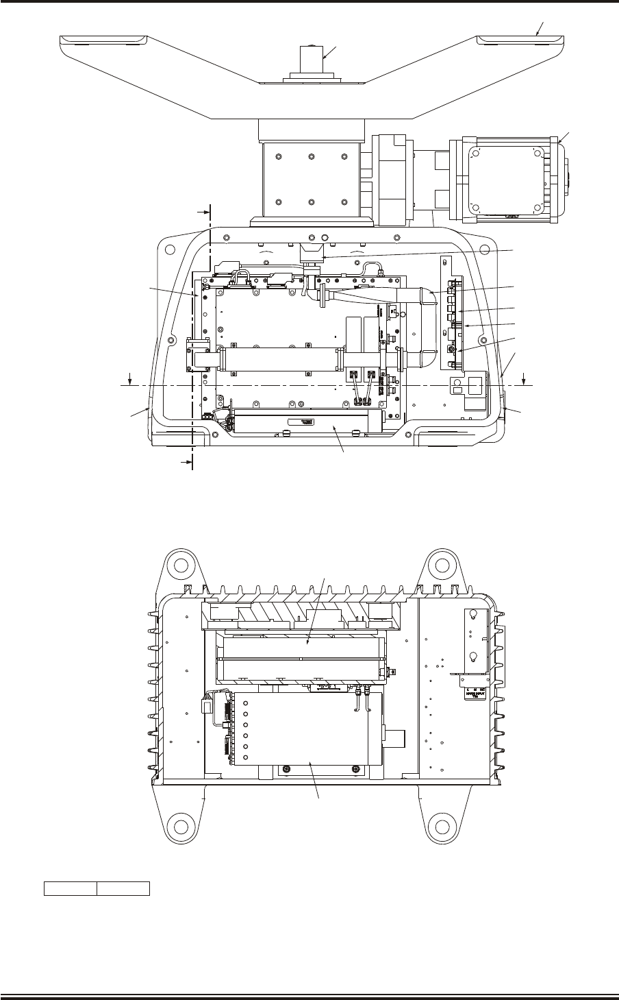
KH1264
Chap ter 7
Page 7.4Is sue 2
SECTION ON A-A
DOOR REMOVED FOR CLARITY
DTX-A115
KELVIN HUGHES
RADAR TRANSCEIVER
FMS090-5600
SERIAL No.
MOD:-
ISOLATE
MAINS BEFORE
SERVICING
ISOLATE
MAINS BEFORE
SERVICING
ACHACH
A
B
B
A
3
CD-7427 ISSUE 1
4
2
5
7
5
8
6A
6B
6
10,14
9,12
9,13
7
1
Figure 1 - X-band Upmast Transceiver (DTX-A3): Main Assemblies

PL1 - X-band Upmast Transceiver (DTX-A3): Parts List
ITEM NUMBER DESCRIPTION KELVIN HUGHES
Part No.
1ENCODER AZ/HL GTX-A188
2MOTOR & GEARBOX 3 PHASE 55-100-0273-001
3ROTATING JOINT 45-750-0034-001
4ANTENNA SUPPORT CASTING LPA-1129
5SharpEyeTM X BAND TX ASSY DTX-A115
6SWITCH AND CAN ADAPTER PCA ASSY DTX-A150
6A CAN ADAPTER PCB NNR-A981
6B SharpEyeTM AZIMUTH INTERFACE PCB DTX-A151
7POWER SUPPLY TYPE XLC2503-P00A 45-690-0062-002
DC POWER CABLE ASSY DTX-A119
INTERFACE CABLE ASSY DTX-A149
MAINS INPUT CABLE ASSY DTX-A148
8VTS INTERNAL WAVEGUIDE ASSEMBLY DTX-A170
TERMINAL SOCKET 12-WAY TYPE 302 45-925-0390-001
NEON PANEL INDICATOR RED 220V 45-625-0005-001
9EMC GLAND IP68 M16 FORM E 85-290-0071-006
10 GLAND, M25 CABLE DIA. 14-18MM 85-290-0071-003
GLAND M20 CABLE DIA. 9 - 13MM 85-290-0071-002
11 BLANKING PLUG M16X1.5 BRASS 85-290-0081-001
12 GLAND BLANKING DISC 55-100-0210-003
13 GLAND BLANKING DISC 55-100-0210-002
14 GLAND BLANKING DISC 55-100-0210-001
BLANKING PLUG M25 85-290-0080-001
BLANKING PLUG M16X1.5 BRASS 85-290-0081-001
FITTING KIT MANTA S BAND GTX-A144
KH1264
Chap ter 7
Is sue 2 Page 7.5
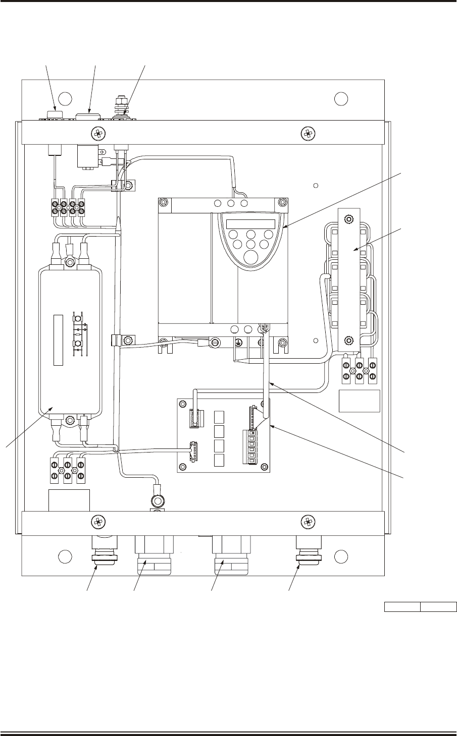
KH1264
Chap ter 7
Page 7.6Is sue 2
CD-7287 ISSUE 1
TOSHIBA
PRG RUN RUN
MON
ENT STOP
E R/L1 S/L2
UT/1 VT/2 W/T
1
L E
PLA
SCHAFFNER
FN2070M-12-06
P
N
E
P
N
1
6
TB1
U V W
OUTPUT
TB2
7
6
2
3 5 4
8
N
MAINS INPUT
9,11 10,12 9,1110,12
Figure 2 - Drive Control Unit (GTX-A24): Main Assemblies

PL2 - Drive Control Unit (GTX-A24): Parts List
ITEM NUMBER DESCRIPTION KELVIN HUGHES
Part No.
1INVERTER PT No.VFNC1S-2022PL-W (TOSHIBA) 45-690-0033-001
2DRIVE INTERFACE PCB GTX-A104
3NEON INDICATOR GREEN 230V No L01770 (LP1) 45-6000-0076-001
4 LED INDICATOR GREEN 6340-305-505G (D1) 45-6000-0049-001
5KEY SWITCH 2 POSITIONS 2A-250V 45-613-4205
6CONTROL CABLEFORM GTX-A197
7POWER OUTPUT CABLEFORM GTX-A196
8POWER INPUT CABLEFORM GTX-A217
MAINS FILTER 12A FN2070M-12-06 45-680-0028-01
9EMC GLAND IP68 M16 FORM E 85-290-0071-006
10 GLAND, M16 CABLE DIA. 6.5-9.5 85-290-0071-004
11 GLAND BLANKING DISC 55-100-0210-003
12 GLAND BLANKING DISC 55-100-0210-001
KH1264
Chap ter 7
Is sue 2 Page 7.7

THIS PAGE INTENTIONALLY BLANK
KH1264
Chap ter 7
Page 7.8Is sue 2

INSTALLATION AND SERVICE REPORTS
This section is reserved for customer use and the following information should be inserted
into the manual:
1Installation Reports and Records
2Service Reports and Records
3Copy of Warranty Card
4Other relevant documentation
KH1264
Reports
Is sue 2 Page 1

THIS PAGE INTENTIONALLY BLANK
KH1264
Reports
Page 2Is sue 2