Kelvin Hughes DTX-A1 RADAR 2.9 TO 3.1 GHz User Manual KH2060 Issue 2 vp
Kelvin Hughes Limited RADAR 2.9 TO 3.1 GHz KH2060 Issue 2 vp
Users Manual

US ERS MAN UAL
OPERATING INFORMATION
for the
MantaDigital Navigation Displays
RADAR MODE
PUB LI CA TION KH2060
IS SUE 5
Radar Soft ware Version ZM-2144 V1.2
Jan u ary 2009
Kel vin Hughes Limited
New North Road, Hainault, Il ford, Essex IG6 2UR, UK
Tele phone: +44 20 8502 6887
Fac sim ile: +44 20 8559 8526
Telex: 896401
www.kelvinhughes.com
Registered Office: New North Road, Hainault, Essex, IG6 2UR
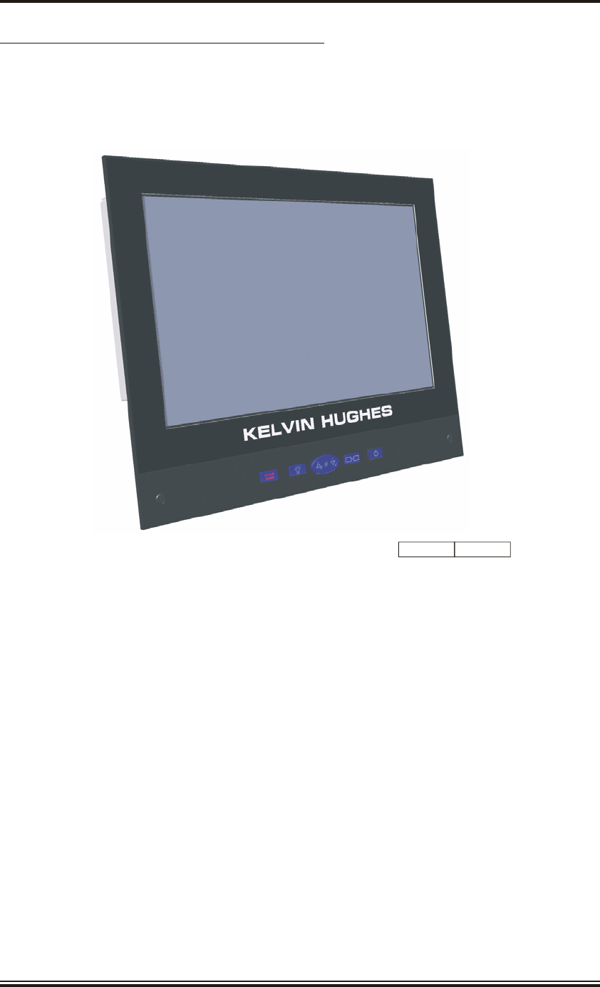
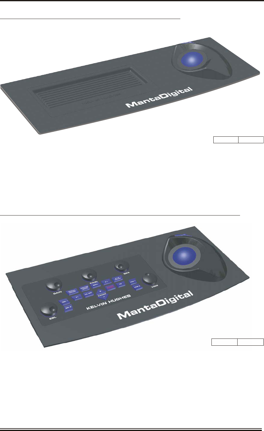
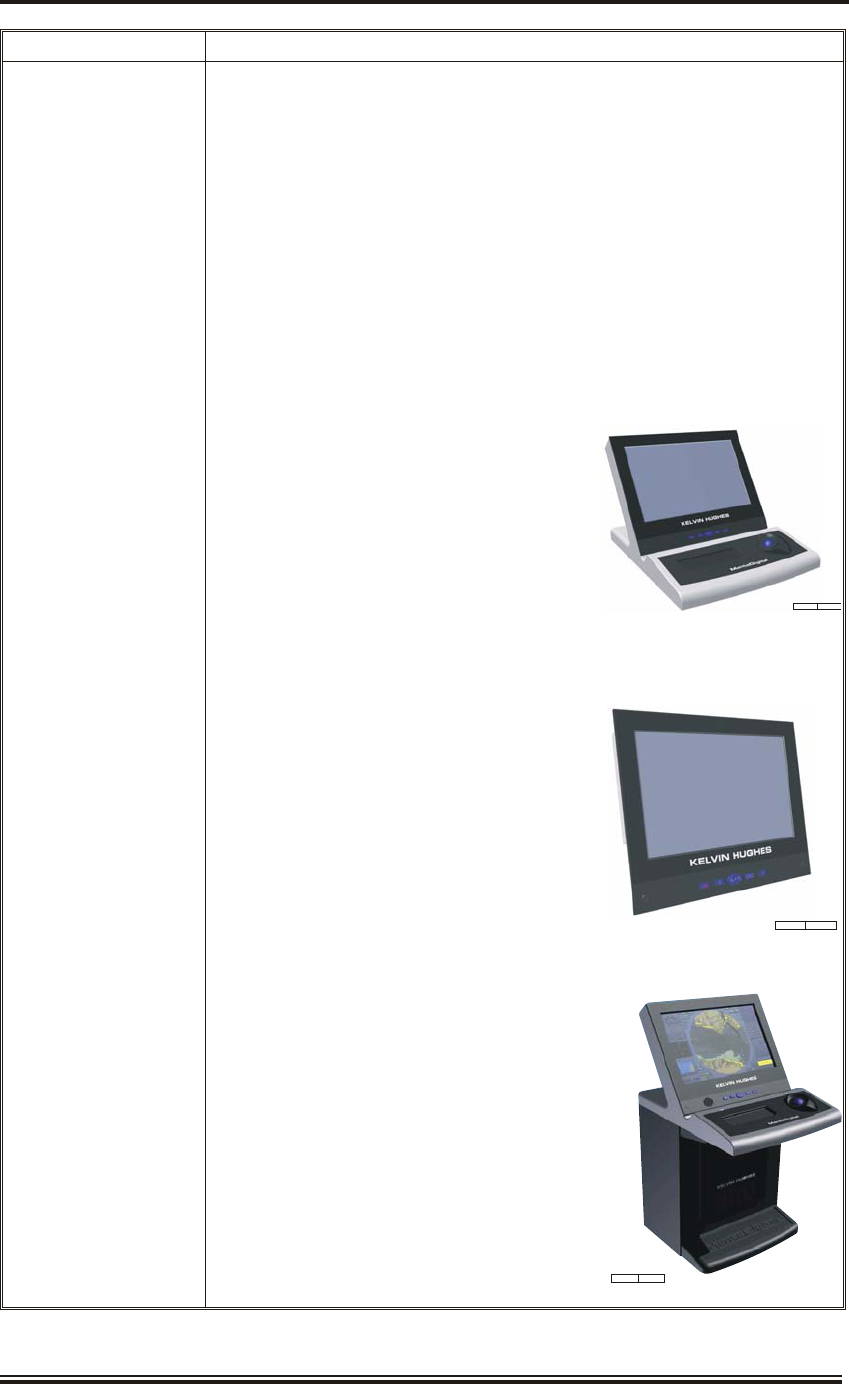
Incorporated in England No. 1030135
VAT No: GB 918080917/000

CONFORMITY STATEMENT
MantaDigital Radar is certified to conform to the requirements of MSC.192(79) and has been
tested to IEC 62388.
The MantaDigital navigation radar display (processor, user interface and presentation screen)
meets the requirements for Standard and High Speed Craft. The navigation radar display is
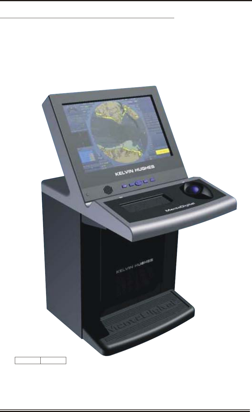
offered in both Category 1 and Category 2 options. Category 1 is defined as all ships/craft
³10,000 gt and Category 2 is defined as ships/craft from 500 gt to <10,000 gt and HSC
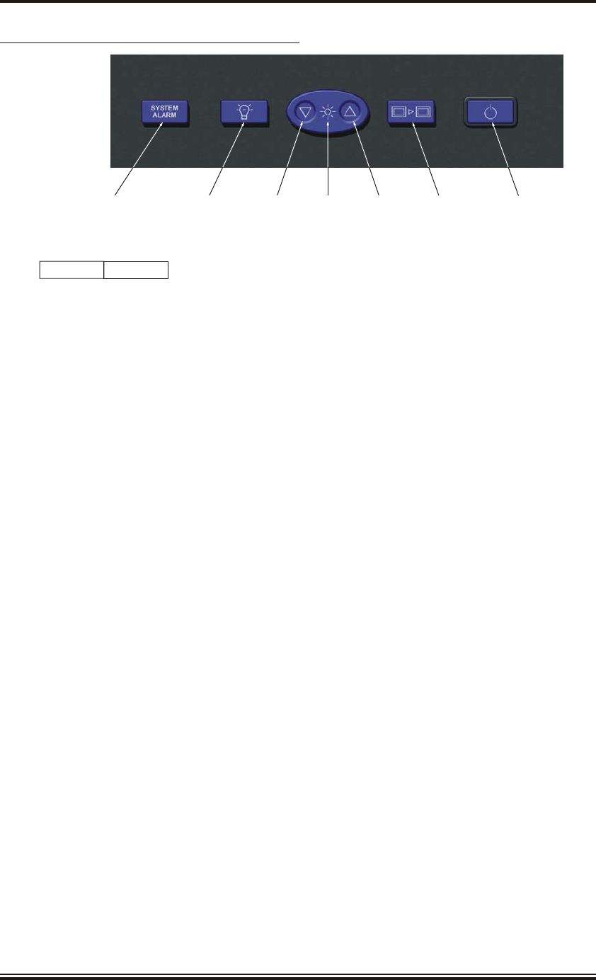
<10,000 gt.
Radar sensors are provided in both X-band and S-band versions and meet the requirements
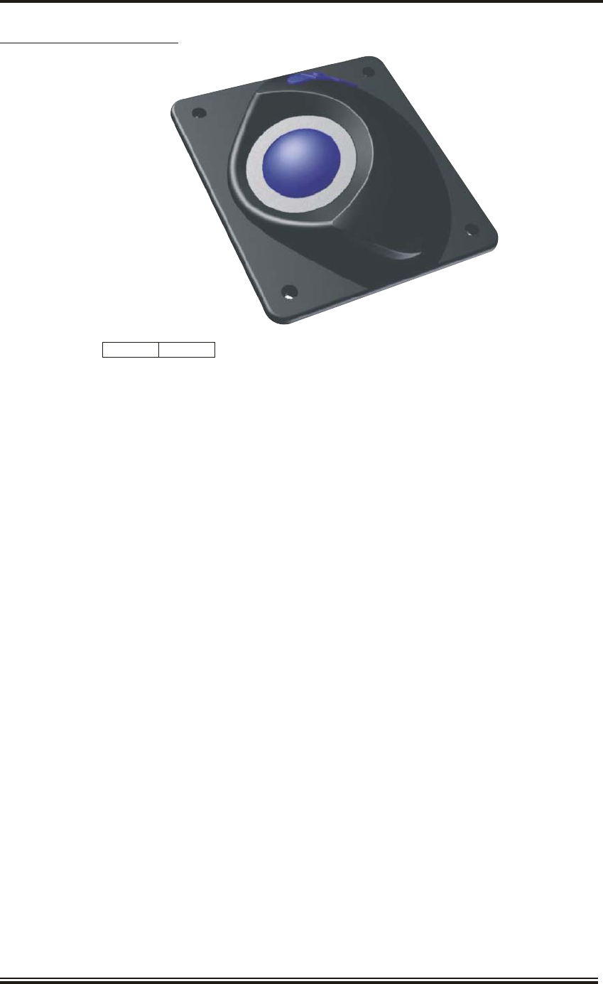
for Standard and High Speed Craft.
COPYRIGHT
ã Copyright Kelvin Hughes Limited. 2009
All rights reserved. No part of this publication may be
reproduced, transmitted, transcribed, translated or stored
in any form or by any means, without the written
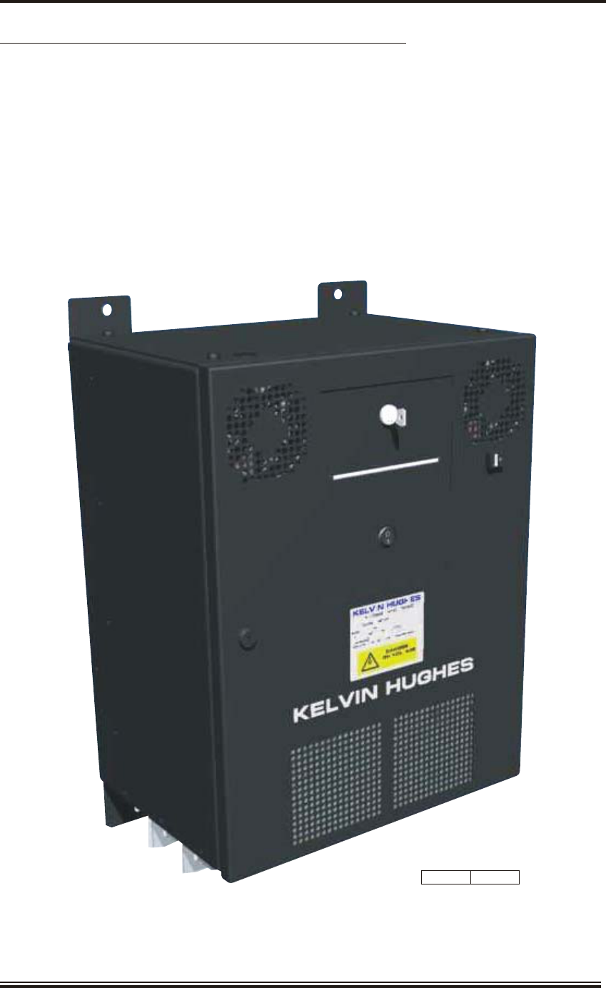
permission of Kelvin Hughes Limited.
Technical details contained in this publication are subject to
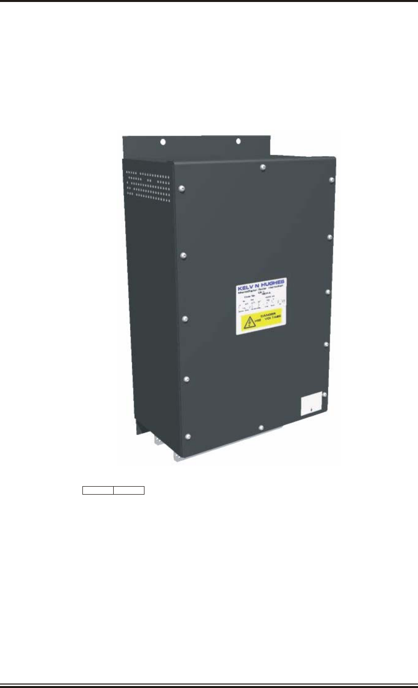
change without notice.
Page ii Issue 5 (Jan 09)
KH2060
Prelims

AMENDMENT RECORD
When an amendment is incorporated into this handbook, the details should be recorded below. If the
equipment has been modified, the modification number is shown on the Amendment instruction page.
Amendment No. Date Inserted Initials Mod Number
-
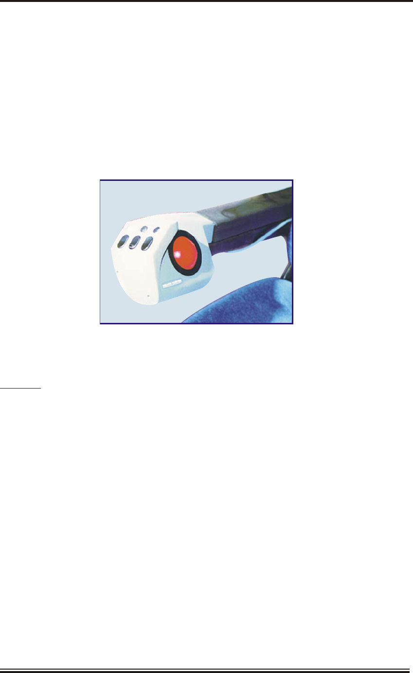
Issue 5 (Jan 09) Page iii
KH2060
Prelims

THIS PAGE INTENTIONALLY BLANK
Page iv Issue 5 (Jan 09)
KH2060
Prelims

CONTENTS
Title Page I
Conformity Statement and Copyright Page ii
Amendment Record Sheet iii
Contents (This Page) v
Electric Shock Resuscitation vii
Safety Warnings viii
Handling of Electrostatic Sensitive Semiconductor Devices xii
Preface xiii
List of Abbreviations xv
SECTION 1 - INTRODUCTION AND GENERAL DESCRIPTION (KH2060-1)
SECTION 2 - SWITCHING ON AND OFF
OPERATING INFORMATION FOR THE MANTADIGITAL RADAR
(KH 3200 Issue 4)
SECTION 3 - MAINTENANCE (KH2060-4)
Issue 5 (Jan 09) Page v
KH2060
Prelims

THIS PAGE INTENTIONALLY BLANK
Page vi Issue 5 (Jan 09)
KH2060
Prelims
Issue 5 (Jan 09) Page vii
KH2060
Prelims
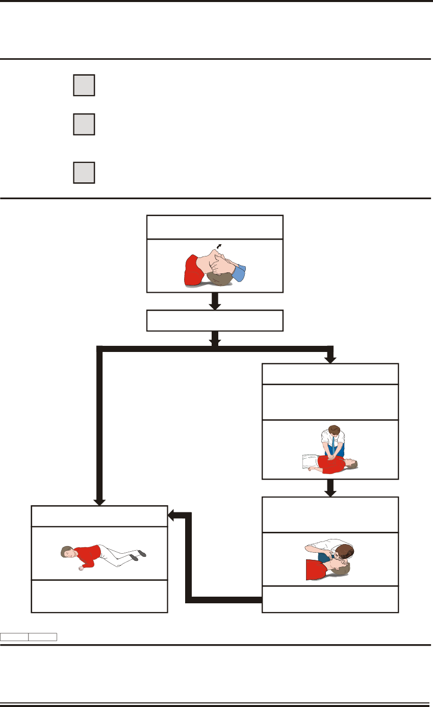
ELECTRIC SHOCK RESUSCITATION
1SHOUT FOR HELP.
SWITCH OFF ELECTRICITY IF POSSIBLE.
REMOVE CASUALTY FROM DANGER.
REMOVE ANY OBVIOUS OBSTRUCTION TO BREATHING.
SWITCH OFF ELECTRICITY IMMEDIATELY. IF NOT POSSIBLE, DON'T WASTE TIME SEARCHING FOR A SWITCH
SAFEGUARD YOURSELF WHEN REMOVING CASUALTY FROM HAZARD.
IF CASUALTY IS STILL IN CONTACT WITH ELECTRICITY AND THE SUPPLY CANNOT BE ISOLATED, STAND ON A DRY
NON-CONDUCTING MATERIAL (RUBBER MAT, WOOD, LINOLEUM). USE RUBBER GLOVES, DRY CLOTHING WOODEN BROOM,
STOOL, CHAIR, LENGTH OF DRY ROPE OR WOOD TO PULL OR PUSH CASUALTY AWAY FROM THE HAZARD.
IF CASUALTY IS NOT BREATHING, START RESUSCITATION AT ONCE.
GET HELP.
MEDICAL ASSISTANCE MAY BE OBTAINED ON / AT ...............................................
2
3
SHOUT & SHAKE CASUALTY (FOR RESPONSE)
LOOSEN NECKWARE,
TILT HEAD BACKWARDS & PUSH CHIN UPWARDS
PERFORM CPR:
HEEL OF HAND IN CENTRE OF BREASTBONE
WITH OTHER HAND ON TOP (FINGERS OFF CHEST)
WRISTS & ELBOWS LOCKED COMPRESS DOWN 5cm.
REPEAT 30 TIMES IN TOTAL (SPEED 100 PER MINUTE)
HEART HAS STOPPED BEATING, LAY CASUALTY
ON THEIR BACK ON FIRM SURFACE eg. FLOOR
SIGNS OF LIFE/CIRCULATION PRESENT
CHECK FOR SIGNS OF CIRCULATION,
SIGNS OF LIFE (< 10 SECONDS).
WHEN NORMAL BREATHING COMMENCES,
PLACE CASUALTY IN RECOVERY POSITION
KEEP CASUALTY AT REST.
MOVE USING A STRETCHER.
WATCH CLOSELY, PARTICULARLY FOR DIFFICULTY
IN BREATHING. LIGHTLY COVER WITH BLANKETS
OR OTHER MATERIALS
SIGNS OF LIFE/CIRCULATION ABSENT
CD-1265 ISSUE 2
CONTINUE CPR WITH 30 CHEST COMPRESSIONS,
THEN 2 BREATHS UNTIL CASUALTY REVIVES &
COLOUR IMPROVES, OR HELP ARRIVES
OR YOU ARE EXHAUSTED.
OPEN AIRWAY, PINCH THE NOSE & HOLD THE CHIN.
TAKE NORMAL BREATH, SEAL MOUTH,
BLOW STEADILY (WATCHING CHEST RISE).
REMOVE MOUTH, CHECK THAT CHEST FALLS,
REPEAT RESCUE BREATH.
SAFETY WARNINGS
Page viii Issue 5 (Jan 09)
KH2060
Prelims
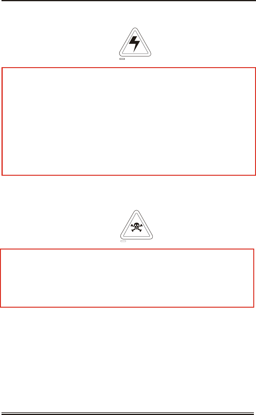
WARNING
THIS EQUIPMENT CON TAINS MA TERIALS WHICH PRO DUCE TOXIC FUMES
WHEN BUR NT.
CD-0844
WARNING
THIS EQUIPMENT IS NOT FIT TED WITH SAFETY IN TERLOCKS. LE THAL
VOLTAGES ARE PRES ENT WHEN THE UNITS ARE OPEN AND EX POSED. BE -
FORE RE MOVING ANY SUB-UNIT OR PCB, ALL SUP PLIES MUST BE
SWITCHED OFF.
A CUR RENT OF 100 mA PASSING THROUGH THE HU MAN BODY FOR ONE
SECOND CAN KILL. THIS CAN OC CUR AT VOLT AGES AS LOW AS 35 V AC
OR 50 V DC. SOME EQUIPMENT IN THE SYS TEM USES ELEC TRICAL POWER
THAT CAN BE LE THAL.
CD-0845

SAFETY WARNINGS
Issue 5 (Jan 09) Page ix
KH2060
Prelims
SER VICING
THE EQUIPMENT SHOULD BE SER VICED BY AUTHORISED
AGENTS ONLY.
Pic ture Freeze
The rare event of Pro cessor fail ure is in dicated by non-operation of the trackerball, no
update of screen data, and the time shown on the Vi sual Dis play Unit will not be up -
dated.
The Pro cessor Unit is to be switched OFF and ON again to re set the Pro cessor.
Mains Volt age
All Kel vin Hughes equipment is supplied with Mains Volt age set for 220V,
50/60 Hz AC un less stated oth erwise on la bels at tached to the equipment.
WARNING
The nav igation systems and equip ment supplied by Kel vin Hughes com ply with the
rel evant SOLAS reg ulations and are pro vided as aids to nav igation and should be
used in ac cor dance with the SOLAS reg ulations.

RA DI A TION HAZ ARD: NON-ION IS ING
ANTENNA RA DI A TION HAZ ARD: IN JURY CAN RE SULT FROM EX PO SURE
TO THE MAIN BEAM OF A STA TIONARY RA DAR ANTENNA. DO NOT STAND
LESS THAN 2m FROM THE CEN TRAL FRONT FACE OF THE ANTENNA.
It is ac cepted in most coun tries that no sig nificant haz ard is pre sented by ra dio
frequency mean power den sity lev els up to 10mW/cm. RF power lev els in ex cess of this
may cause harm ful ef fects, par ticularly to the eyes.
Users of car diac pace makers should be aware that ra dio fre quency transmissions can
damage some such de vices or cause ir regularities in their op eration. Per sons us ing a
pacemaker should as certain whether their de vice is likely to be af fected be fore
exposing themselves to the risk of mal function.
X-RAY RA DI A TION
30 kW S- band and 25kW X- band magnetrons have a stray field of less than 0.00525
gauss at 4.6m. The latest X-band magnetrons have a stray field of less than 0.002 gauss
at 2.1 m.
At a distance of 100 mm with S-band and X-band magnetrons operating normally into
a matched load, no level of ionising radiation above the background is detectable.
SAFETY ALOFT
AE RIAL RO TA TION: BE FORE MAIN TE NANCE TO THE TURN ING
MECH A NISM TAKES PLACE, DIS ABLE AE RIAL RO TA TION.
When working aloft, en sure that it is brought to the at tention of someone in au thority
at deck or at ground level and that suit ably placed warning no tices are posted warning
that work aloft is in prog ress. En sure that the means of ac cess aloft is se cure and
beware of wet or slip pery lad der rungs and working ar eas.
When work ing on or near a ra dar scan ner and other mov ing or RF ra diating
equipment, en sure that it is switched off and that the fuses have been re moved and
re tained.
Page x Issue 5 (Jan 09)
KH2060
Prelims

MI CRO WAVE RA DI A TION LEV ELS.
Measurement of radiation levels were conducted on 10th July 2008 at QinetiQ. The
manufacturer’s representative assisted and enabled the antenna rotation to be disabled
and transmission maintained. Test equipment used was a Narda survey meter mod
8718B and an isotropic probe mod 8721 ser no 13003. A table of results is presented
below.
System 100 W/m2 distance or
power at Antenna face
50 W/m2
distance
10 W/m2
distance
25 kW S-Band CTX-A9 with
3.9 m Low profile S-Band Antenna LPA-A3
28.4 W/m2- 510 mm
25 kW X-Band CTX-A8-ACAC with
1.3 m Low profile X-Band Antenna LPA-A13
71.7 W/m260 mm 880 mm
SharpEye DTX-A1 with
3.9 m Low profile S-Band Antenna LPA-A3
21.7 W/m2- 90 mm
Issue 5 (Jan 09) Page xi
KH2060
Prelims

Page xii Issue 5 (Jan 09)
KH2060
Prelims
CAU TION
HAN DLING OF ELEC TRO STATIC-SENSITIVE SEMI CON DUC TOR
DE VICES
Certain semiconductor devices used in the equipment are liable to damage due
to static voltage. Observe the following precautions when handling these
devices in their unterminated state, or sub-units containing these devices:
Persons removing sub-units from an equipment containing these devices must
be earthed by a wrist strap and a resistor at the point provided on the
equipment.
Soldering irons used during the repair operations must be low voltage types
with earthed tips and isolated from the mains voltage by a double insulated
transformer.
Outer clothing worn must be unable to generate static charges.
Printed Circuit Boards (PCBs) fitted with these devices must be stored and
transported in anti-static bags.
Fit new devices in a special handling area.

PREFACE
MantaDigital Radar is designed to be flexible and expandable making it ideal for use in
Integrated Bridge Systems (IBS) and Integrated Navigation Systems (INS), as well as for
standalone Radar Systems.
When used in Integrated Bridge Systems or Integrated Navigation Systems the MantaDigital
Widescreen Display can be configured as a networked Multi-Functional Navigation Display,
which can be switched between different functions, e.g. Radar, ECDIS, HAP or Conning
Display, depending on the function required by the user. This allows a single display to
control a number of functions, although only one function can be accessed at any time.
MantaDigital is designed so that, when required, the display units can be controlled from a
remote position using an Ergopod.
The operation, installation and maintenance of MantaDigital is covered in the following
manuals:
KH2060 - User Manual for the MantaDigital Radar Systems. This covers operation
and maintenance of the MantaDigital Radar System, including the Radar Display and
Radar Sensors. This manual provides all the information required for standalone radar
systems, and for the networked multi-functional display in Radar Mode.
KH2061 - System Manual for the MantaDigital Radar Systems. This covers
installation and commissioning of the MantaDigital Radar system, including stand
alone Radar Systems, and the networked multi-functional multi-display systems.
Maintenance must only be undertaken by qualified service engineers or by Kelvin
Hughes and their approved agents. Unauthorised repair of equipment during the
Warranty period will invalidate the Warranty. If a third party wishes to undertake the
maintenance of the equipment, ensure that the service engineers have undertaken a
training course approved by Kelvin Hughes.
Issue 5 (Jan 09) Page xiii
KH2060
Prelims

If a unit exhibits a fault, and therefore a service engineer is required to attend the vessel,
please contact our Service Control Centre, giving full details of the following:
1. Name of vessel (Phone or Fax number if fitted)
2. Equipment type
3. Software status (version number) (if applicable)
4. Next port of call, ETA/ETD and ship's agents
5. Fault description (with as much detail as possible)
6. Purchase order number with invoicing details
7. Contact Name
You may contact our direct line, send a fax or send an email.
Kelvin Hughes, Customer Services Group, New North Road, Hainault, Essex IG6 2UR
(UK)
Phone: Main UK Switchboard: 44 (0)20 8502 6887
Direct Service Line & Out of Hours Emergency Technical Support: 44 (0)20 498 1761
email: service@kelvinhughes.co.uk
If you have any technical queries or require any technical information regarding your Kelvin
Hughes bridge equipment you may phone our direct Service Line. You may also contact our
direct line, send or fax an email to:
technical.advice@kelvinhughes.co.uk
If you require information on our training facilities or would like to have a quote for training,
please give as much detail as possible. You may contact our direct line, send a fax or send an
email to:
training@kelvinhughes.co.uk
For quotation of spares, or if you require any information regarding availability, lead times
etc, you may contact our direct line, send a fax or send an email to:
spares@kelvinhughes.co.uk
Please Note. All quote requests must have full contact details. Our preferred method of
contact is email, but Fax or Post may be used. We normally supply the quotation by email.
For more in formation re garding our contract ser vices or to ar range a meeting with a mem ber
of our team you may email us at the fol lowing ad dress. Those cus tomers al ready hold ing an
agreement with us may also use this email ad dress to re quest a ser vice, pro viding the same
information as men tioned for ser vice (no pur chase or der num ber re quired). You may con tact
our di rect line, send a fax or send an email to:
contract.support@kelvinhughes.co.uk
Page xiv Issue 5 (Jan 09)
KH2060
Prelims

LIST OF ABBREVIATIONS
ACK Acknowledge
ACQ Acquire, Acquisition
ADJ Adjust, Adjustment
AFC Automatic Frequency Control
AGC Automatic Gain Control
AIS Automatic Identification System
ALT Altitude
AM Amplitude Modulation
ANCH Anchor Watch
ANCH Vessel at Anchor
ANT Antenna
AP Autopilot
API Application Program Interface
APR April
ARM Armoured Protected Memory
ARCS Admiralty Raster Chart Service
ARPA Automatic Radar Plotting Aid
AUD Audible
AUG August
AUTO Automatic
AUX Auxiliary System/Function
AVAIL Available
AZ Acquisition Zone
AZI Azimuth Indicator
BCR Bow Crossing Range
BCT Bow Crossing Time
BITE Built In Test Equipment
BKGND Background
BRG Bearing
BRILL Brilliance
BWW Bearing Waypoint to Waypoint
C Carried (for example, carried EBL origin)
CAL Calibrate
cbl cable length
CCRP Consistent Common Reference Point
CCRS Consistent Common Reference System
CCTV Closed Circuit Television
CD Compact Disk
CDROM Compact Disk Read Only Memory
CENT Centre
CHG Change
CLR Clear
CNCL Cancel
COG Course Over Ground
CONT Contrast
CORR Correction
CP Circularly Polarised
Issue 5 (Jan 09) Page xv
KH2060
Prelims

LIST OF ABBREVIATIONS (CONT.)
CPA Closest Point of Approach
cps cycles per second
CPU Central Processing Unit
CRS Course
CSM Crash Survivable Module
CTS Course To Steer
CTW Course Through the Water
C UP Course Up
CURS Cursor
D Dropped (e.g. dropped EBL origin)
DAU Data Acquisition Unit
DAY/NT Day/Night
DEC December
DECR Decrease
deg degrees
DEL Delete
DEP Departure
DEST Destination
DEV Deviation
DIU Data Interface Unit
DISP Display
DIST Distance
DIVE Vessel Engaged in Diving Operations
DG Dangerous Goods
DGLONASS Differential GLObal’naya NAvigatsionnaya Sputnikovaya Sistema
tr: Differential Global Navigation Satellite System
DGNS Differential GNSS
DGPS Differential GPS
DMTS Discrete Monitor Timing Standard
DPTH Depth
DR Dead Reckoning
DRG Vessel Engaged in Dredging or Underwater Operations
DRMS Distance Root Mean Square
DSC Digital Selective Calling
DTG Distance To Go
E East
EBL Electronic Bearing Line
EBRL Electronic Range & Bearing Line
ECDIS Electronic Chart Display and Information System
ECS Electronic Chart System
ECTAB Electronic Chart Table (Kelvin Hughes)
EGNOS European Geo-stationary Navigational Overlay System
ENC Electronic Navigational Chart
ENH Enhance
ENT Enter
EP Estimated Position
EPA Electronic Plotting Aid
Page xvi Issue 5 (Jan 09)
KH2060
Prelims

LIST OF ABBREVIATIONS (CONT.)
EPFS Electronic Position Fixing System
EPIRB Emergency Position Indicating Radio Beacon
EQUIP Equipment
EPROM Erasable Programmable Read Only Memory
ERBL Electronic Range and Bearing Line
ERR Error
ETA Estimated Time of Arrival
ETD Estimated Time of Departure
EUT Equipment Under Test
EXT External
EZ Exclusion Zone
FEB February
FISH Fishing Vessel
FM Frequency Modulation
fm fathom
FREQ Frequency
FSP Field Service Program
ft foot
FTC Fast Time Constant
FWD Forward
GAS Grounding Avoidance System
GC Great Circle
GDOP Geometric Dilution of Precision
GEOG Geographics
GHz GigaHertz
GLONASS Global Orbiting Navigation Satellite System
GMDSS Global Maritime Distress and Safety System
GMT Greenwich Mean Time (also known as Zulu time)
GND Ground
GNSS Global Navigation Satellite System
GPS Global Positioning System
GRI Group Repetition Interval
GRND Vessel Aground
gt gross tonnage
GZ Guard Zone
HAP Harbour Approach and Pilotage
HCS Heading Control System
HDG Heading
HDOP Horizontal Dilution of Precision
HF High Frequency
HL Heading Line
hPa HectoPascal
hr hour
HS Harmful Substances (applies to AIS)
HSC High Speed Craft
H UP head up
Issue 5 (Jan 09) Page xvii
KH2060
Prelims

LIST OF ABBREVIATIONS (CONT.)
HVR Hardened Voyage Recorder
Hz Hertz
IBS Integrated Bridge System
ID Identification
IEC International Electrotechnical Commission
IMO International Maritime Organisation
INCR Increase
IND Indication
INF RED Infrared
INFO Information
INIT Initialisation
INP Input
INS Integrated Navigation System
INT Interval
I/O Input/Output
IP Internet Protocol
IR Interference Rejection
IRCS Integrated Radio Communication System
ISW Interswitch
ITU-R International Telecommunication Union - Radiocommunication sector
JAN January
JUL July
JUN June
kHz kiloHertz
km kilometre
kn knots
kPa kiloPascal
LAT Latitude
LBL Label
LCD Liquid Crystal Display
LED Light Emitting Diode
LF Low Frequency
LIM Limit
L/L Latitude/Longitude
LON Longitude
LOP Line of Position
LOST TGT Lost Target
LP Long Pulse
LR Long Range
LWY Leeway
m metres
MAG Magnetic
MAN Manual
MAR March
MAX Maximum
MF Medium Frequency
Page xviii Issue 5 (Jan 09)
KH2060
Prelims

LIST OF ABBREVIATIONS (CONT.)
MIN Minimum
min minute
MHz MegaHertz
MKR Marker
MMSI Maritime Mobile Service Identity
MOB Man Overboard
MON Performance Monitor
MP Medium Pulse
MP Maritime Pollutant (applies to AIS)
ms milli-seconds
MSI Maritime Safety Information
MSTR Master
MVR Manoeuvre
N North
NAV Navigation
NLT Not less than
NM Nautical Miles
NMEA National Marine Electronics Association
NMT Nor more than
NORM Normal
NOV November
NUC Vessel Not Under Command
N UP North-Up
OCT October
OOW Officer On Watch
OS Ownship
PAD Predicted Area of Danger
PANEL Panel Illumination
PAST POSNPast Positions
PASSV Passenger Vessel
PC Personal Computer
PCB Printed Circuit Board
PDOP Positional Dilution of Precision
PERM Permanent
PI Parallel Index Line
PIN Personal Identification Number
PILOT Pilot Vessel
PL Pulse Length
PM Pulse Modulation
PM Performance Monitor
PMC Protective Memory Capsule
POB Person Overboard
PORT Port/Portside
POSN Position
PPC Predicted Point of Collision
PPI Plan Position Indicator
PPR Pulses Per Revolution
Issue 5 (Jan 09) Page xix
KH2060
Prelims

LIST OF ABBREVIATIONS (CONT.)
PRED Predicted
PRF Pulse Repetition Frequency
PRR Pulse Repetition Rate
PWR Power
RAD Radius
RADAR RAdio Detection And Ranging
RAIM Receiver Autonomous Integrity Monitoring
RAM Random Access Memory
RATS Rate Aided Tracking System
RCDR Receiver
RCDS Raster Chart Display System
RCGA Radar Control Gate Array
RCS Radar Cross-Section (target size)
REF Reference
REF Echo Reference
REL Relative
RIM Vessel Restricted in Manoeuvrability
RIP Radar Interlay Processor
RIU Radar Interswitch Unit
RL Rhumb Line
RM Relative Motion
RM(R) Relative Motion, Relative Trails
RM(T) Relative Motion, True Trails
RMS Root Mean Square
RNC Raster Navigational Chart
RNG Range
ROM Read Only Memory
RORO Roll On/Roll Off Vessel
ROT Rate Of Turn
ROV Remotely Operated Vehicle
RP Radar Plotting
RPM Revolutions Per Minute
RR Range Rings
RTD Real Time Display
RTK Real-Time Kinematic
Rx Receiver
S South
SAIL Sailing Vessel
SAM Status and Alarm Unit
SAR Search And Rescue
SART Search And Rescue Transponder
SARV Search And Rescue Vessel
SAT Satellite
SATNAV SATellite NAVigation
SC/SC Scan to Scan (Correlation)
SDME Speed and Distance Measuring Equipment
sec second
Page xx Issue 5 (Jan 09)
KH2060
Prelims

LIST OF ABBREVIATIONS (CONT.)
SEL Select
SEP September
SEQ Sequence
SF CNT Safety Contour
SIM Simulation
SINAD SIgnal to Noise And Distortion
SNR Signal to Noise Ration
SNTP Standard Time Network Protocol
SOG Speed Over Ground
SOLAS Safety Of Life At Sea
SP Short Pulse
SPD Speed
STAB Stabilised
STBD Starboard/Starboard Side
STBY Standby
STC Swept Time Constant
STG Speed To Go (Required Speed)
STN Station
STW Speed Through the Water
S-VDR Simplified Voyage Data Recorder
SYM Symbol
SYNC Synchronised
T True
TCPA Time to Closest Point of Approach
TCP/IP Transmission Control Protocol/Internet Protocol
TCS Track Control System
TCVR Transceiver
TD Time Difference
TDOP Time Dilution of Precision
TFTP Text File Transfer Protocol
THD Transmitting Heading Device
TIU Transceiver Interface Unit
TGT Target
TM True Motion
TM(T) True Motion, True Trails
TMTR Transmitter
TOA Time Of Arrival
TOD Time Of Departure
TOW Vessel Engaged in Towing Operations
TPL Transferred Line of Position
TPR Transponder
TRIG Trigger Pulse
TRK Track
TRKG Tracking
TT Target Tracking
TTG Time To Go
TTL Transistor Transistor Logic
Issue 5 (Jan 09) Page xxi
KH2060
Prelims

LIST OF ABBREVIATIONS (CONT.)
Tx Transmit
TWOL Time to Wheel Over Line
UHF Ultrahigh Frequency
ULB Underwater Locator Beacon
UNSTAB Unstabilised
UPS Uninterruptible Power Supply
USB Universal Serial Bus
UPS Uninterruptible Power Supply
UTC Co-ordinated Universal Time
UTM Universal Transverse Mercator
UWE Vessel Underway Using Engine
VAR Variation
VCD Vessel Constrained by Draught
VCR Video Cassette Recorder
VDR Voyage Data Recorder
VDU Visual Display Unit
VECT Vector
VESA Video Electronics Standards Association
VHF Very High Frequency
VID Video
VLF Very Low Frequency
VOY Voyage
VRM Variable Range Marker
VTS Vessel Traffic Service
W West
WAT Water
WCV Waypoint Closure Velocity
WGS World Geodetic System
WOL Wheel Over Line
WOP Wheel Over Point
WOT Wheel Over Time
WPT Waypoint
XTD Cross Track Distance
XTE Cross Track Error
yd yards
Page xxii Issue 5 (Jan 09)
KH2060
Prelims

KH2060-1
INTRODUCTION AND GENERAL DESCRIPTION
CONTENTS
Para Page
Issue 5 (Jan 09) Page 1.1
KH2060-1
1 IN TRO DUC TION 1.3
13 RA DAR DISPLAYS 1.10
15 Widescreen Vi sual Display Units 1.10
19 Desk Top Mounted Ra dar Display (MDD-A30-*) 1.11
21 Console Mounted Ra dar Display (MDD-A20-*) 1.12
26 Pedestal Mounted Ra dar Dis play (MDD-A1-* or MDD-A9-*) 1.13
28 Vi sual Dis play Unit Con trols and In di ca tors 1.14
30 Trackerball (MDD-A110) 1.15
33 Con sole Mounted Trackerball and Key board (MDD-A101) 1.16
35 Con sole Mounted Trackerball and Pen cil Tray (MDD-A100) 1.17
36 Con sole Mounted Trackerball and MantaDigital Control In ter face (MDD-A102) 1.17
38 MantaDigital Ra dar Pro cessor Unit (MDP-A1 or MDP-A9) 1.19
41 RADAR INTERSWITCH UNIT (RIU) (MDP-A12) 1.20
44 TRANS MIT TER IN TER FACE UNIT (TIU) (NNR-A66-ABAB) 1.20
47 ERGOPOD (NNR-A18) 1.21
50 Con trols 1.21
50 Func tion Pushbuttons 1.21
51 Range (-) & (+) Pushbuttons 1.21
52 Trackerball 1.21
53 SWITCHING ON AND OFF 1.22
53 Switch ing On 1.22
55 Switch ing Off 1.22
59 TECH NI CAL OVERVIEW 1.23
61 MantaDigital Widescreen Vi sual Display Unit 1.24
64 Visual Display Unit 1.25
67 MantaDigital Ra dar Processor Unit (MDP-A1 or MDP-A9) 1.26
73 Radar Interswitch Unit (RIU) (MDP-A12) 1.26
76 Trans mit ter In ter face Unit (TIU) (NNR-A66-ABAB) 1.26
79 Ra dar Sensor 1.27
81 Ergopod 1.28
82 SYS TEM SPEC I FI CA TIONS 1.28

CONTENTS (CONT.)
ILLUSTRATIONS
Figure Page
Page 1.2 Issue 5 (Jan 09)
KH2060-1
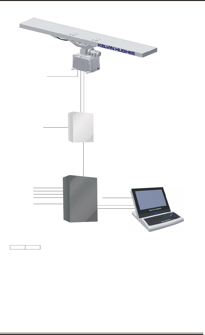
1 Typical X-Band Downmast Single Radar System 1.5
2 Typical S-Band Downmast Single Radar System 1.6
3 Typical S-Band Upmast Single Radar System 1.7
4 Typical X-Band and S-Band Upmast Dual Radar System 1.8
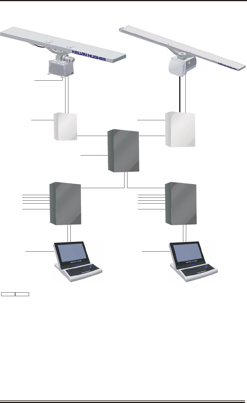
5 Typical S-Band SharpEyeTM Upmast and X-Band Downmast Dual Radar System 1.9
6 Desk Top Mounted Radar Display 1.11
7 Console Mounted Radar Display 1.12
8 Pedestal Mounted Radar Display 1.13
9 VDU Controls 1.14
10 Trackerball 1.15
11 Trackerball and Keyboard 1.16
12 Trackerball and MantaDigital Control Interface (MCI) 1.17
13 Trackerball and Pencil Tray 1.17
14 MantaDigital Radar Processor (MDP-A1, -A9) 1.19
15 Radar Interswitch Unit (MDP-A12) 1.20
16 Ergopod 1.21
17 Typical MantaDigital Radar System Schematic Diagram 1.23

KH2060-1
INTRODUCTION AND GENERAL DESCRIPTION
IN TRO DUC TION
1 The MantaDigital Radar System is designed and manufactured to be compliant with the
IMO MSC.192(79) Radar Performance Standard. These advanced radar systems have
been tested and certified to Test Standard IEC 62388.
2 The MantaDigital Radar System includes a radar sensor (transceiver and antenna /
turning unit), and a navigation Radar Display (processor unit, visual display unit,
trackerball and optional keyboard, optional MantaDigital Control Interface and optional
Ergopod). The radar sensor consists of either a conventional non-coherent magnetron pulsed
radar operating on X-band (9.41 GHz) or S-band (3.05 GHz) or optionally, utilises a
new-technology coherent solid state S-band transceiver (SharpEyeTM) (frequency selectable in
the band 2.93 GHz to 3.07 GHz). The transceivers operate with one of a range of low profile
antennas and associated turning units.
3 The high performance navigation Radar Display processor unit interfaces and controls
the radar sensor(s), provides display functionality including advanced digital signal
processing, and handles the User inputs. The processor unit also provides the drive for a high
resolution wide-aspect flat screen visual display unit. The user input is via a trackerball and three
buttons and optionally, a MantaDigital Control Interface featuring dedicated hardware controls
for the primary control functions, or a keyboard. All MantaDigital Radar Displays provide
automatic target tracking and Automatic Identification System (AIS) functionality.
4 The display presentation recognises the IMO MSC.191(79) Presentation Standard to
provide harmonisation with a new generation of navigation Radar Displays. A standard
use of symbols, readability, screen performance and colour grouping has been adopted to aid the
user and to reduce stress on the bridge of a ship.
5 The MantaDigital navigation Radar Display, as part of a certified system, is compliant
with the IMO Radar Performance Standard. The MantaDigital Radar Display
presentation benefits from the wide screen format and may be configured in various formats
including presentations as a single radar presentation, a dual radar presentation, and a single
radar presentation with harbour approach features; all of these presentations support the IMO
Radar Performance Standard. Additional presentation options are regarded as Auxiliary
Displays, for example the Harbour Approach and Pilotage Display. Such presentation
configurations may be essential for the navigational task in hand and can provide partial radar
functionality, however they are not regarded as part of an approved and certified radar system.
6 A system may be installed for example, as a radar presentation with map functions, a
chart radar featuring electronic charts, a radar for high speed craft, or a combination of
these. Equipment certification and category signify the suitability for each application and the
User Manual addresses each equipment category.
Issue 5 (Jan 09) Page 1.3
KH2060-1

7 MantaDigital may be used as stand-alone systems, or as part of an Integrated Bridge
System (IBS) or Integrated Navigation System (INS). A radar installation can comprise a
single stand-alone radar system or may include multiple radar systems with possibilities to
interswitch sensors and displays.
8 This manual contains information on all the operational features of the MantaDigital
Radar System. The operational features that are provided on individual systems may
vary according to the customer's requirements. Therefore, the Visual Display Unit, User
Interface, Processor Unit and Radar Sensor used on individual systems may not appear identical
to those shown in this manual. Where a particular feature is not active, that feature and associated
facilities will not be shown as a option in the menus or will be greyed out.
9 The MantaDigital Radar System is available as Radar only (MDP-A1) or as a Chart
Radar (MDP-A9).
10 KH3200, the Radar operating information manual, which is bound with KH2060,
provides the full operating procedures for the Radar software, and is applicable to all
systems, regardless of the hardware installation.
11 The MantaDigital Radar System consists of a combination of the following items:
(1) MantaDigital Radar Display, comprising a MantaDigital Widescreen Visual
Display Unit, a Processor Unit and a user interface (trackerball with optional
keyboard and/or optional MantaDigital Control Interface). The Visual Display
Unit is either Desk, Pedestal or Console mounted, and is available in two sizes
(520 mm (20") with a 258 mm diameter Radar Operational Area and 650 mm
(26") with a 328 mm diameter Radar Operational Area). The associated
Processor Unit is either bulkhead mounted or located in the same Pedestal as the
Visual Display Unit. Console mounted Visual Display Units have a separate
Trackerball Unit, and a separate optional keyboard or optional MantaDigital
Control Interface.
(2) Radar Sensor, available in S-Band (Mk7 and SharpEyeTM) or X-Band (Mk4,
Mk5 and Mk7), comprising a Radar Transceiver, Turning Mechanism and
Antenna. The Mk7 S-Band is a magnetron radar, available in upmast or
downmast configuration, and also uses a Drive Control Unit. The SharpEyeTM
S-Band is a solid-state radar, available in upmast configuration only and also uses
a Drive Control Unit. The X-Band radar sensors are magnetron radars, available
in upmast configuration (Mk4 and Mk5) or downmast (Mk7) configuration, and
also use a Tx Interface Unit.
(3) Radar Interswitch Unit (RIU). This unit is used where more than one Radar
Sensor and/or more than one Radar Display are used on the system. It allows up to
6 Radar Sensors and 6 Radar Displays to be connected together, allowing each
Radar Display to select any of the Radar Sensors connected to the RIU for
viewing.
(4) Ergopod (optional), which is a remote control module, mounted on the end of a
chair arm, and allows the user to control the radar display functions from the chair
position rather than from the visual display unit position, this facility is normally
used in addition to the standard trackerball control.
Page 1.4 Issue 5 (Jan 09)
KH2060-1
12 Typical MantaDigital Radar Systems are shown in Figures 1 to 5.
NOTE: The single radar systems shown in Figures 1 to 3 have no redundancy built in. In the
event of a single equipment failure the whole radar system may cease to function.
Issue 5 (Jan 09) Page 1.5
KH2060-1
WAVEGUIDE
SIGNAL & POWER
CD-7395 ISSUE 3
MantaDigital
WIDESCREEN PEDESTAL UNIT
MDD-A1-* or MDD-A9-*
LOG
GYRO
(D)GPS
POWER 110V/220V AC
NOT TO SCALE
Mk 5 X-BAND
TURNING MECHANISM
CAE-A30-22, -23
LOW PROFILE ANTENNA
LPA-A13, -A19, -A25
SIGNAL & CONTROL
25kW X-BAND
DOWNMAST
Tx/Rx
CTX-A8-ACAC
POWER 110V/220V AC
AIS
Figure 1 - Typical X-Band Downmast Single Radar System
Page 1.6 Issue 5 (Jan 09)
KH2060-1
S-BAND
TURNING MECHANISM
GTX-A11
LOW PROFILE ANTENNA
LPA-A3
WAVEGUIDE
SIGNAL & POWER
SIGNAL & CONTROL
CD-7396 ISSUE 2
NOT TO SCALE
MantaDigital
WIDESCREEN PEDESTAL UNIT
MDD-A1-* or MDD-A9-*
LOG
GYRO
(D)GPS
POWER 110V/220V AC
SIGNAL & CONTROL
30kW S-BAND
DOWNMAST
Tx/Rx
CTX-A9
POWER 110V/220V AC
DRIVE
CONTROL
UNIT
GTX-A24
POWER 220V AC
AIS
MOTOR POWER
Figure 2 - Typical S-Band Downmast Single Radar System
Issue 5 (Jan 09) Page 1.7
KH2060-1
CD-7394 ISSUE 1
VIDEO
CONTROL
MantaDigital
WIDESCREEN DESKTOP DISPLAY UNIT
MDD-A30-20 or MDD-A30-26
LOG
GYRO
(D)GPS
POWER 110V/220V AC
NOT TO SCALE
Mk 7 S-BAND 30kW
UPMAST TRANSCEIVER
GTX-A16
LOW PROFILE ANTENNA
LPA-A3
MOTOR POWER
SIGNAL & CONTROL
POWER 110V/220V AC
SIGNAL & CONTROL
DRIVE
CONTROL
UNIT
GTX-A24
POWER 220V AC
POWER 110V/220V AC
MantaDigital
RADAR
PROCESSOR
MDP-A1
or MDP-A9
AIS
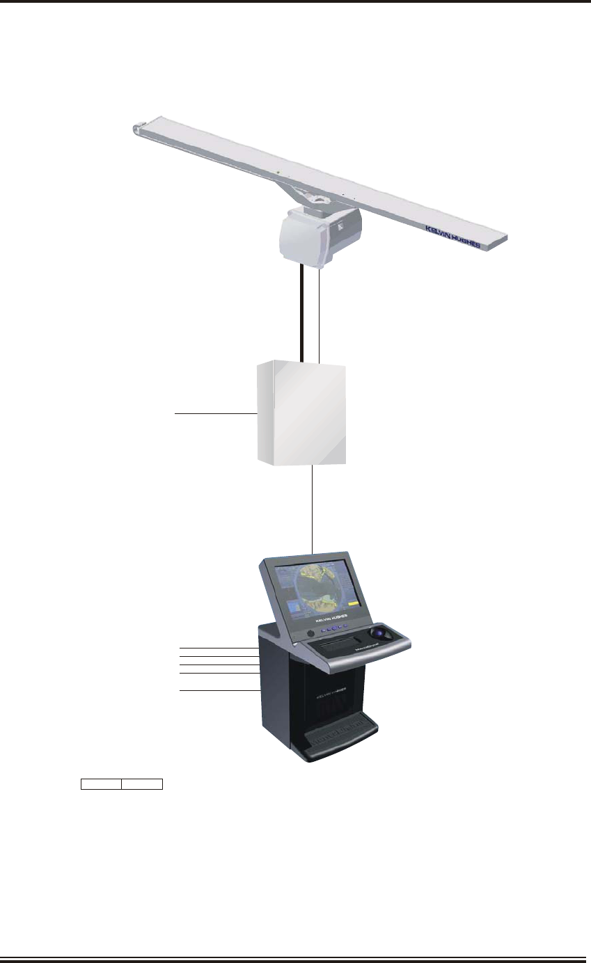
Figure 3 - Typical S-Band Upmast Single Radar System
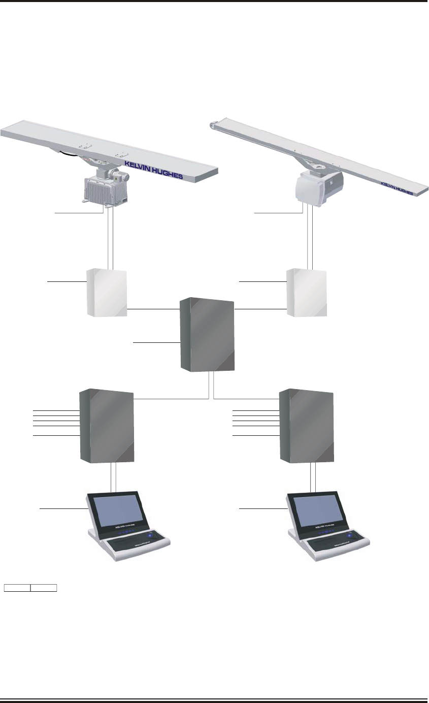
NOTE: The dual radar systems shown in Figures 4 and 5 use the Radar Interswitch Unit to
distribute the radar data from the radar sensors to the radar displays. In the event of the
Radar Interswitch Unit failing, each radar sensor will be connected to its default radar
display (as set up on installation) allowing the system to operate with reduced
functionality. This allows the system to have some operational capability in the event of a
single point of failure.
Page 1.8 Issue 5 (Jan 09)
KH2060-1
Mk7S-BAND30kW
UPMAST TRANSCEIVER
GTX-A16
LOW PROFILE ANTENNA
LPA-A3
MOTOR POWER
SIGNAL & CONTROL
POWER 110V/220V AC
CD-7398 ISSUE 2
POWER 110V/220V AC
NOT TO SCALE
MOTOR POWER
SIGNAL & CONTROL
POWER 110V/220V AC
SIGNAL & CONTROL
POWER 220V AC
RADAR
INTERSWITCH
UNIT
MDP-A12
DRIVE
CONTROL
UNIT
GTX-A24
POWER 110V/220V AC
VIDEO
CONTROL
MantaDigital
WIDESCREEN DESKTOP DISPLAY UNIT
MDD-A30-20 or MDD-A30-26
LOG
GYRO
(D)GPS
POWER 110V/220V AC
POWER 110V/220V AC
MantaDigital
RADAR
PROCESSOR
MDP-A1
or MDP-A9
VIDEO
CONTROL
MantaDigital
WIDESCREEN DESKTOP DISPLAY UNIT
MDD-A30-20 or MDD-A30-26
LOG
GYRO
(D)GPS
POWER 110V/220V AC
POWER 110V/220V AC
MantaDigital
RADAR
PROCESSOR
MDP-A1
or MDP-A9
SIGNAL & CONTROL
SIGNAL & CONTROL SIGNAL & CONTROL
LOW PROFILE ANTENNA
LPA-A13, -A19, -A25
Tx
INTERFACE
UNIT
NNR-A66
-ABAB
AIS AIS
Mk 5 X-BAND
TURNING MECHANISM
CAE-A30-20, -21,
Figure 4 - Typical X-Band and S-Band Upmast Dual Radar System
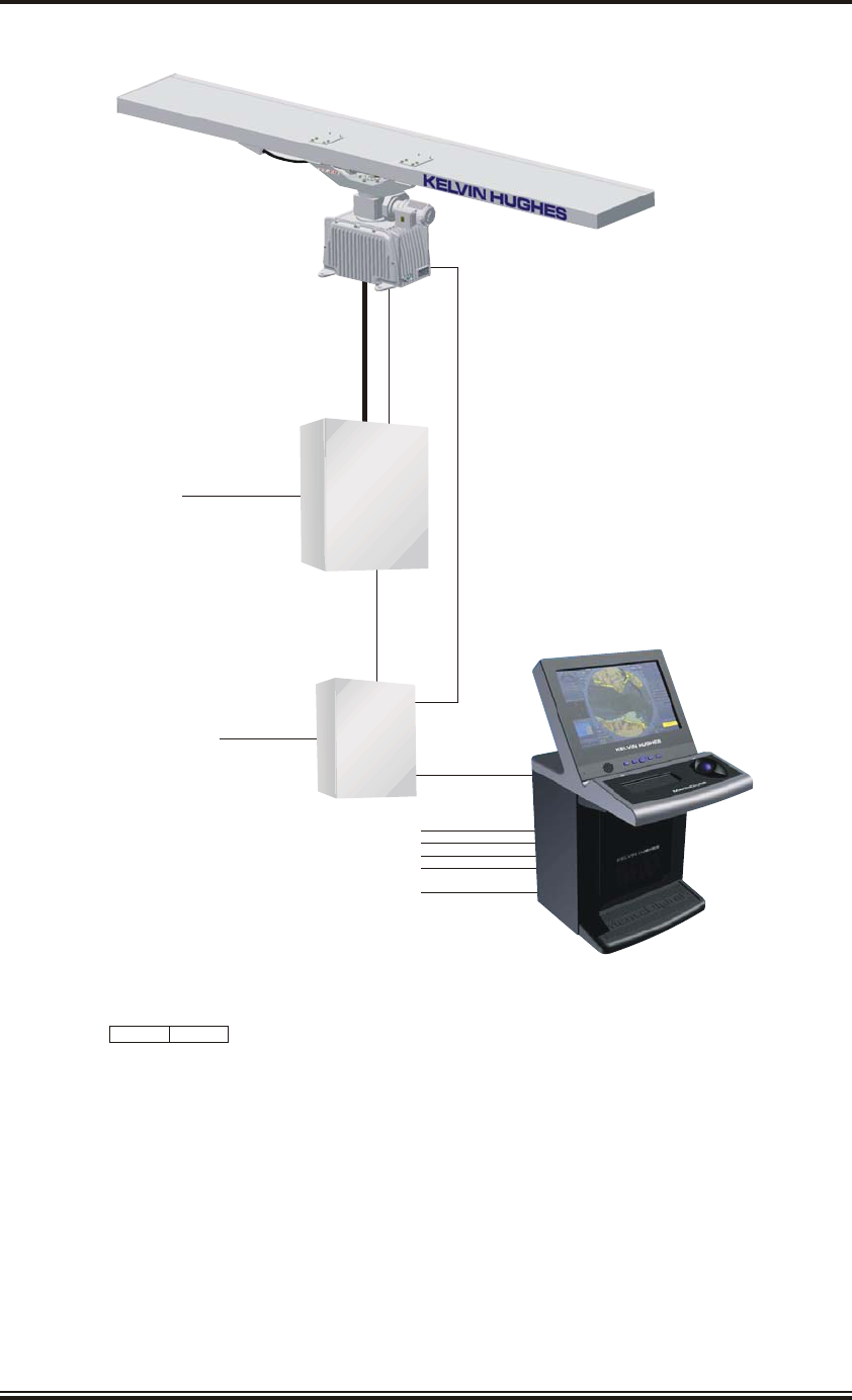
Issue 5 (Jan 09) Page 1.9
KH2060-1
WAVEGUIDE
SIGNAL & POWER
CD-7397 ISSUE 1
POWER 110V/220V AC
NOT TO SCALE
MOTOR POWER
SIGNAL & CONTROL
POWER 110V/220V AC
SIGNAL & CONTROL
POWER 220V AC
RADAR
INTERSWITCH
UNIT
MDP-A12
SharpEye
S-BAND UPMAST
TRANSCEIVER
DTX-A1
LOW PROFILE ANTENNA
LPA-A3
POWER 110V/220V AC
VIDEO
CONTROL
MantaDigital
WIDESCREEN DESKTOP DISPLAY UNIT
MDD-A30-20 or MDD-A30-26
LOG
GYRO
(D)GPS
POWER 110V/220V AC
POWER 110V/220V AC
MantaDigital
RADAR
PROCESSOR
MDP-A1
or MDP-A9
VIDEO
CONTROL
MantaDigital
WIDESCREEN DESKTOP DISPLAY UNIT
MDD-A30-20 or MDD-A30-26
LOG
GYRO
(D)GPS
POWER 110V/220V AC
POWER 110V/220V AC
MantaDigital
RADAR
PROCESSOR
MDP-A1
or MDP-A9
SIGNAL & CONTROL
SIGNAL & CONTROL SIGNAL & CONTROL
Mk5X-BAND
TURNING MECHANISM
CAE-A30-22
LOW PROFILE ANTENNA
LPA-A13, -A19, -A25
25kW X-BAND
DOWNMAST
Tx/Rx
CTX-A8-ACAC
DRIVE
CONTROL
UNIT
GTX-A24
AIS AIS
Figure 5 - Typical S-Band SharpEyeTM Upmast and X-Band Downmast Dual Radar
System

RA DAR DISPLAYS
13 The MantaDigital Radar Displays are available in the following configurations:
(1) Desk Top Mounted Radar Display, comprising a Visual Display Unit complete
with trackerball and optional keyboard or MantaDigital Control Interface.
(2) Console Mounted Radar Display, comprising a Visual Display Unit with
separate console mounted keyboard or MantaDigital Control Interface.
(3) Pedestal Mounted Radar Display, comprising a Visual Display Unit complete
with trackerball and optional keyboard or MantaDigital Control Interface,
mounted on a pedestal with the Processor Unit.
14 The main user interface is via the trackerball and three pushbuttons associated with the
MantaDigital Widescreen Visual Display Units, or from the optional Ergopod. The
Visual Display Unit has an ON/OFF switch, which is the main user on/off control. The
MantaDigital Processor Unit and Radar Interswitch Unit also have ON/OFF switches, which are
normally left in the ON position, and are only set to OFF for servicing. The MantaDigital Radar
Processor Unit contains the DVD-ROM drive, which is used to load chart data onto the system
(chart radars only).
Widescreen Visual Dis play Units
15 The MantaDigital Widescreen Visual Display Units use flat screen technology and are
available in two sizes (520 mm (20") with a 258 mm diameter Radar Operational Area
and 650 mm (26") with 328 mm diameter Radar Operational Area), with the option of desk
mounting, console mounting, or pedestal mounting.
16 The Desk Mounted Visual Display Units have the trackerball and three pushbutton
controls built in to the unit, and, if required, a keyboard or MantaDigital Control
Interface; whereas the Console Mounted Visual Display Units are designed to be used in
conjunction with a separate Trackerball (complete with three pushbuttons) and either a
QWERTY keyboard or a MantaDigital Control Interface (MCI). The MantaDigital Control
Interface provides dedicated controls for the primary radar functions.
17 The MantaDigital Widescreen Visual Display Units are designed to be connected to a
MantaDigital Processor Unit.
18 The MantaDigital Radar Displays can be controlled from an optional Ergopod.
However, as the Ergopod does not have a keyboard, the on-screen virtual keyboard is
used.
Page 1.10 Issue 5 (Jan 09)
KH2060-1
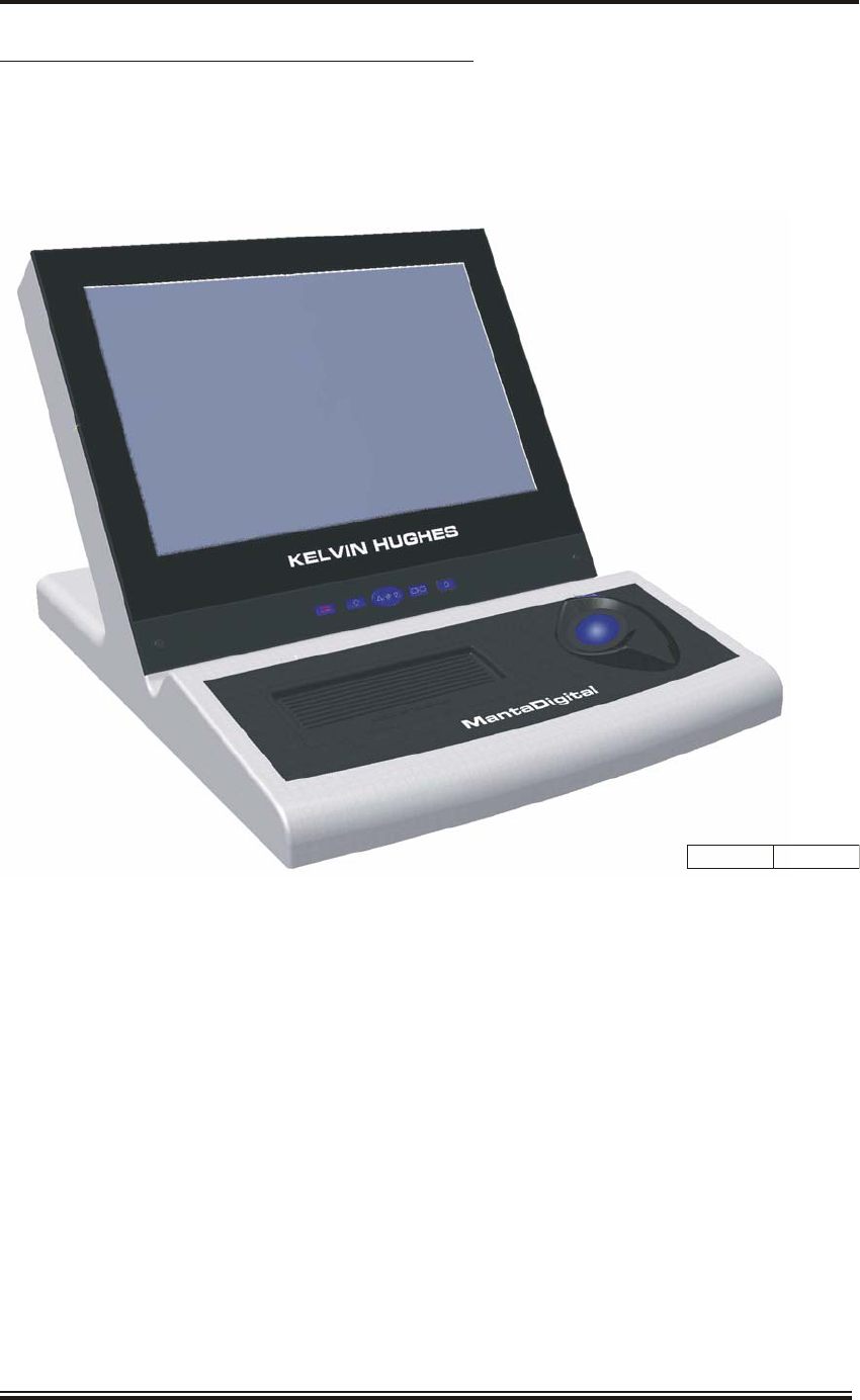
Desk Top Mounted Ra dar Dis play (MDD-A30-*)
19 The Desk Top Radar Display Unit comprises a plastic moulding, which houses a flat
screen LCD visual display unit, trackerball and an optional tactile feel compact keyboard
or a MantaDigital Control Interface. The Desk Top Radar Display Unit is shown in Figure 6. The
Desk Top Radar Display Unit is mounted on the Pedestal for pedestal mounted configurations.
20 A trackerball unit with three pushbuttons are mounted on the bezel in front of the visual
display unit. Optionally a keyboard or MantaDigital Control Interface may be fitted to
the unit.
Issue 5 (Jan 09) Page 1.11
KH2060-1
CD-7247 ISSUE 1
Figure 6 - Desk Top Mounted Radar Display
Console Mounted Ra dar Dis play (MDD-A20-*)
21 The Console Mounted Radar Display Unit comprises a plastic bezel moulding, fitted
around the flat screen LCD visual display unit.
22 The Console Mounted Radar Display Unit is shown in Figure 7.
23 The Console Mounted Radar Display Unit requires the use of a Trackerball Unit
(MDD-A110) or a console mounted trackerball and pencil tray assembly (MDD-A100).
24 Optionally a console Mounted Trackerball and MantaDigital Control Interface (MCI)
unit (MDD-A102) or a console mounted Trackerball and Keyboard Unit (MDD-A101)
are available.
25 The Trackerball unit comprises a large diameter, backlit trackerball and three push
buttons for control. The Keyboard is a 75 key QWERTY style. Both the Trackerball and
Keyboard connect directly to the widescreen visual display unit.
Page 1.12 Issue 5 (Jan 09)
KH2060-1
CD-7248 ISSUE 1
Figure 7 - Console Mounted Radar Display
Pedestal Mounted Ra dar Dis play (MDD-A1-* or MDD-A9-*)
26 The pedestal mounted Radar Display Unit provides a convenient self contained
workstation containing a flat screen LCD visual display unit, a processor and a user
control interface. The design is such that a number of pedestal units may be installed side-by side
to create a unified console.
27 Two sizes of pedestal unit are available one with a 520 mm (20") visual display unit and
one with a 650 mm (26") visual display unit.
Issue 5 (Jan 09) Page 1.13
KH2060-1
CD-7246 ISSUE 2
Figure 8 - Pedestal Mounted Radar Display
Vi sual Dis play Unit Con trols and In di ca tors
28 The Visual Display Unit has the following controls and indicators:
(1) System Alarm. When a system alarm occurs the button is brightly lit and the
audible alarm sounds. Press the button to acknowledge the alarm and the audible
alarm is silenced.
(2) Trackerball and button backlight (light bulb symbol). Sets the level of
backlighting for the trackerball. Pressing and holding the button increases the
level of backlighting to the maximum level and then switches to minimum
backlighting (off) and starts to increase the level again. Continually pressing and
releasing the button increments the backlighting to maximum level, the next
press switches the backlight to minimum level. Levels starts to increase again as
the button is pressed.
(3) Screen backlight (down and up). Sets the level of backlighting for the visual
display unit screen. The down button decreases the level of backlighting and the
up button increases the level of backlighting. Note that pressing the down and up
buttons together resets the screen backlight to a default setting. This allows the
user to reset the backlight in the event of selecting the wrong lighting levels for
the ambient conditions, which could cause the screen to appear black. Pressing
and holding the down and up buttons for 3 seconds resets the brightness to the
previously selected level, i.e. the previously selected Daylight, Dusk or Night
setting.
(4) Display Select. This button allows the user to scroll through different system
functions, e.g. radar, ECDIS, and select a function for viewing and control. It is
only applicable to Integrated Bridge Systems or Integrated Navigation Systems
using networked displays and processors. It is not used with stand-alone displays
and processors.
(5) System On/Off. When pressed switches the complete system On or Off.
29 A loudspeaker is also incorporated within the visual display unit to provide an audible
alarm.
Page 1.14 Issue 5 (Jan 09)
KH2060-1
SYSTEM
ALARM
TRACKERBALL
AND BUTTON
BACKLIGHT
SCREEN
BACKLIGHT
DISPLAY
SELECT
SYSTEM
ON/OFF
DOWN UP
CD-7406 ISSUE 1
Figure 9 - VDU Controls
Trackerball (MDD-A110)
30 The trackerball controls the on-screen cursor and is used for example to change
parameters, select modes, functions, objects, highlight data, select text. The cursor is
shown as an arrow, cross-hair or square on the screen, depending on the function being used
(refer to the operating instructions in KH3200 for full details).
31 Three pushbuttons are associated with the trackerball and are used to implement the
functions. The 'Cursor Cue' window on the screen indicates the current function of the
three pushbuttons.
32 The trackerball is blue and has LED backlighting. The brightness of the visual display
unit and trackerball backlighting is fully controllable from the Visual Display Unit,
thereby providing suitable backlighting levels for different ambient lighting conditions, e.g. day,
dusk, night. The backlighting can be switched off, if required.
Issue 5 (Jan 09) Page 1.15
KH2060-1
CD-7253 ISSUE 2
Figure 10 - Trackerball

Con sole Mounted Trackerball and Key board (MDD-A101)
33 The keyboard allows the user to input and edit text when required during chart radar
operation (it is not essential if the system is not a chart radar, but is useful for the AIS
function).
NOTE: For buttons which have a second function shown in blue, the Fn button must be pressed
and held down before pressing the required button to enable the alternative function
(shown in blue). However, the alpha-numeric keys with a second function shown in blue
are toggled between the functions by the Num Lock button not by the Fn button. To
toggle the Num Lock function on or off press the Num Lock button.
34 The keyboard also contains a brightness button (light bulb symbol) which allows the
level of the keyboard backlighting to be set when pressed while the Fn button is held
down. Pressing the button increases the brightness, until maximum brightness is reached. There
are three levels: Off (no backlighting), Low and High. Pressing the button again sets the
brightness to minimum (no backlighting), and the level then increases again as the button is
pressed.
Page 1.16 Issue 5 (Jan 09)
KH2060-1
CD-7255 ISSUE 1
Figure 11 - Trackerball and Keyboard
Con sole Mounted Trackerball and Pen cil Tray (MDD-A100)
35 On systems that do not require either a keyboard or a MantaDigital Control Interface, a
simple pencil tray is provided.
Con sole Mounted Trackerball and MantaDigital Control In terface (MDD-A102)
36 The MantaDigital Control Interface contains dedicated controls for the primary radar
functions. The MantaDigital Control Interface is supplied as an option.
Issue 5 (Jan 09) Page 1.17
KH2060-1
CD-7256 ISSUE 1
Figure 12 - Trackerball and MantaDigital Control Interface (MCI)
CD-7254 ISSUE 1
Figure 13 - Trackerball and Pencil Tray

37 The MantaDigital Control Interface (MCI) incorporates controls for:
(1) Gain rotary control.
(2) Rain anti-clutter rotary control.
(3) Sea anti-clutter rotary control.
(4) EBL 1 and EBL 2 On/Off buttons, with a rotary control to set the position of the
selected EBL.
(5) VRM 1 and VRM 2 On/Off buttons, with a rotary control to set the range of the
selected VRM.
(6) Chart On/Off button.
(7) Vector Mode select button to select True or Relative vectors.
(8) Brilliance button. This button sets the brilliance of the MantaDigital Control
Interface backlight. Press the button to increase brilliance. Once maximum
brilliance is achieved the MantaDigital Control Interface backlight goes to
minimum brilliance and brilliance starts to increase brilliance again.
(9) PI On/Off button, switches parallel index lines on and off.
(10) AIS On/Off button, switches AIS on and off.
(11) HL Off button, when pressed temporarily removes heading line and all other
graphics, except the radar image, from the Radar Operational Area.
(12) Range + and - buttons, to set the range scale.
(13) Alarm Cancel button, silences the audible alarm.
(14) F1 and F2 functions buttons are user configurable to meet operational
requirements.
Page 1.18 Issue 5 (Jan 09)
KH2060-1
MantaDigital Ra dar Processor Unit (MDP-A1 or MDP-A9)
38 The Radar Processor Unit may be bulkhead mounted or fitted into a pedestal unit and
provides the processing of radar data for presenting the radar image on the screen, refer to
Figure 14.
39 The cabling to the unit is via an EMC clamp plate located on the base of the unit.
40 The key operated hinged flap on the front of the Radar Processor Unit provides access to
the Floppy Disk Drive and DVD-ROM Drive. Both the ON/OFF switch on the Processor
Unit and the ON/OFF switch on the Visual Display Unit must be ON for the system to operate.
The DVD-ROM Drive and Floppy Disk Drive allow data to be loaded onto the Radar Processor,
e.g. chart information on Chart Radars.
Issue 5 (Jan 09) Page 1.19
KH2060-1
CD-6885 ISSUE 2
Figure 14 - MantaDigital Radar Processor (MDP-A1, -A9)
RADAR INTERSWITCH UNIT (RIU) (MDP-A12)
41 The Radar Interswitch Unit (RIU) is bulkhead mounted and provides the interface for up
to 6 radar sensors and 6 radar displays.
42 The cabling to the unit is via EMC clamp plates located on the base of the unit.
43 The RIU has an On/Off switch for servicing purposes, located on the base of the unit.
TRANS MIT TER IN TER FACE UNIT (TIU) (NNR-A66-ABAB)
44 The Transmitter Interface Unit (TIU) is bulkhead mounted and provides the interface
between the MantaDigital Processor Unit and the Kelvin Hughes Mk4 and Mk5 Radar
Sensors.
45 The cabling is via EMC clamp plates located on the base of the unit.
46 The TIU has an On/Off switch for servicing purposes, located on the top of the unit.
Page 1.20 Issue 5 (Jan 09)
KH2060-1
CD-7407 ISSUE 1
Figure 15 - Radar Interswitch Unit (MDP-A12)
ERGOPOD (NNR-A18)
47 The Ergopod is de signed for mount ing on the end of a chair arm. It al lows the user to
control the screen func tions from the chair rather than the visual dis play unit.
48 The Ergopod provides the same basic operating facilities as the trackerball and three
pushbuttons on the Radar Displays. In addition, the Ergopod is equipped with a plus (+)
and minus (-) range button, a Clutter button (not used) and a screen select button (not used) -
located on the underside of the main pushbutton area above the trackerball.
49 The Ergopod can be used ‘Stand-alone’ or in Dual configuration with two Ergopods
configured as Master and Slave with shared radar displays.
Con trols
Func tion Pushbuttons
50 The 3 Main pushbuttons are used together with the trackerball to activate/select a
particular function. On-screen guidance as to which button to press is given in the 'Cursor
Cue' window on the screen.
Range (-) & (+) Pushbuttons
51 The Range - and + pushbuttons provide a short-cut to the Range Function on a Radar
Display:
(1) Pressing the minus (-) button decreases the range shown on the screen.
(2) Pressing the plus (+) button increases the range shown on the screen.
Trackerball
52 The Trackerball replicates the unit adjacent to the visual display unit and is used to
position the cursor on the screen, near to or on the function to be activated and to change
parameters once a function is activated.
Issue 5 (Jan 09) Page 1.21
KH2060-1
Figure 16 - Ergopod

SWITCH ING ON AND OFF
Switch ing On
53 Press the System ON/OFF button on the Visual Display Unit to switch the system ON.
The operating system will boot up and the Standby screen will be shown.
54 If the system does not switch on, check the following:
(1) Check that the units are switched on, as follows:
(a) If a Drive Control Unit is fitted, ensure the key on the top of the unit is set to
ON. The MOTOR ON indicator will light indicating that power is applied
to the antenna.
(b) If a Transmitter Interface Unit (TIU) is fitted, ensure the ON/OFF switch on
top of the unit is set to ON.
(2) If a Radar Interswitch Unit (RIU) is fitted, ensure the switch on the base of the
unit is set to ON (note that it is normally left in the ON position when the radar
system is not in use).
(3) Check that the ON/OFF switch on the Processor Unit is switched on (note that it
is normally left in the ON position when the radar system is not in use).
Switch ing Off
55 Under normal conditions the user should return to the Standby screen before switching
the system off. This leaves the Radar system in a suitable state to be switched on again
from the Visual Display Unit.
56 Press the System ON/OFF button on the visual display unit to set the unit to OFF.
57 The Processor Unit, RIU and radar sensors are normally left switched ON, and should
only be switched OFF for maintenance purposes.
58 Refer to KH3200 for the shutdown procedure to return to the Standby screen.
Page 1.22 Issue 5 (Jan 09)
KH2060-1
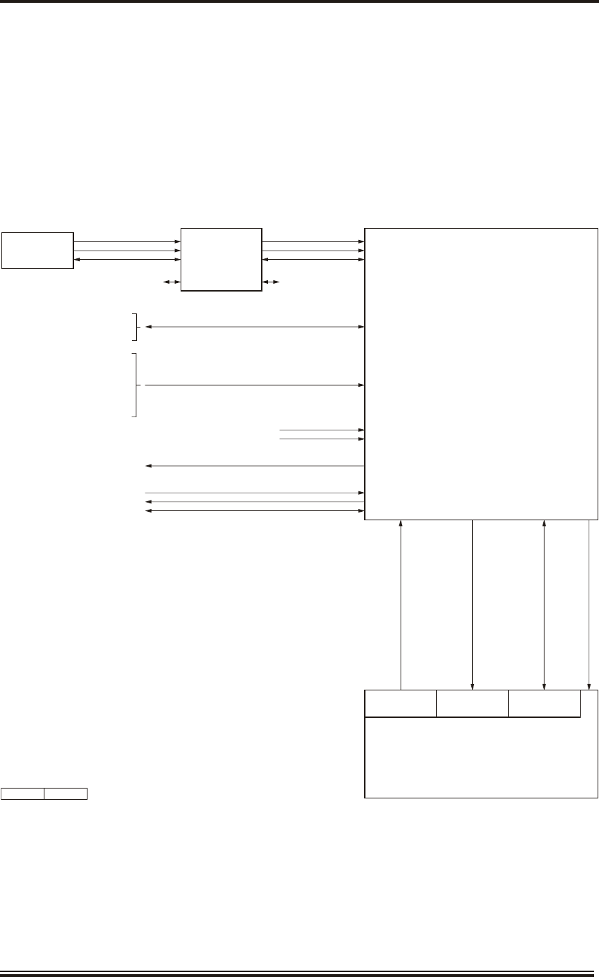
TECH NI CAL OVERVIEW
59 The basic MantaDigital Radar consists of a MantaDigital Visual Display Unit (with a
user interface), and associated MantaDigital Radar Processor Unit; together with a Radar
Sensor consisting of an antenna, turning mechanism and Radar Transceiver.
60 Up to 6 radar sensors and 6 radar displays can be combined into one system using a Radar
Interswitch Unit (RIU). A typical schematic is shown in Figure 17.
Issue 5 (Jan 09) Page 1.23
KH2060-1
MANTA DIGITAL
PROCESSOR UNIT
MDP-A1 or MDP-A9
RADAR
INTERSWITCH UNIT
MDP-A12
MANTA VISUAL
DISPLAY UNIT
TRACKERBALL
& KEYBOARD
VIDEO
NAVIGATION SENSORS
DATE/TIME
POSITION
SPEED
HEADING
DEPTH SENSOR
WIND SPEED/DIRECTION
NMEA SERIAL INPUTS
SHIP'S MAINS (110V/220V)
ALARMS (RELAY ISOLATED)
ETHERNET (PROCESSOR NETWORK)
RADAR VIDEO/SYNC
RADAR AZ/HL
CANBUS
ON/OFF
SWITCH SPEAKER
AUDIO
PROCESSOR ON/OFF
NMEA SERIAL INPUTS/OUTPUTS
ECDIS
ROUTE PLANNING TERMINAL
AUTOPILOT
SERIAL ALARM OUTPUTS
ALARM PANEL
CANBUS
GYRO
SPEED (LOG)
CD-7404 ISSUE 1
UP TO 5 DISPLAYS
RADAR SENSOR
RADAR VIDEO/SYNC
RADAR AZ/HL
CANBUS
UP TO 5 RADAR SENSORS
Figure 17 - Typical MantaDigital Radar System Schematic Diagram

MantaDigital Widescreen Visual Display Unit
61 The basic Widescreen display options are as follows:
MDD-A30-20 520 mm (20-inch) MantaDigital Widescreen Desk Top
Visual Display Unit with pencil tray and Trackerball
MDD-A30-20-ABAA 520 mm (20-inch) MantaDigital Widescreen Desk Top
Visual Display Unit with keyboard and Trackerball
MDD-A30-20-ACAA 520 mm (20-inch) MantaDigital Widescreen Desk Top
Visual Display Unit with MCI and Trackerball
MDD-A30-26 650 mm (26-inch) MantaDigital Widescreen Desk Top
Visual Display Unit with pencil tray and Trackerball
MDD-A30-26-ABAA 650 mm (26-inch) MantaDigital Widescreen Desk Top
Visual Display Unit with keyboard and Trackerball
MDD-A30-26-ACAA 650 mm (26-inch) MantaDigital Widescreen Desk Top
Visual Display Unit with MCI and Trackerball
MDD-A20-20 520 mm (20-inch) MantaDigital Widescreen Console
Mounted Visual Display Unit
MDD-A20-26 650 mm (26-inch) MantaDigital Widescreen Console
Mounted Visual Display Unit
MDD-A1-20 or 520 mm (20-inch) MantaDigital Widescreen Display,
MDD-A9-20 pedestal unit with Radar Processor Unit and Pencil tray
and Trackerball
MDD-A1-20-ABAA or 520 mm (20-inch) MantaDigital Widescreen Visual
MDD-A9-20-ABAA Display Unit, pedestal unit with Radar Processor Unit
and Keyboard and Trackerball
MDD-A1-20-ACAA or 520 mm (20-inch) MantaDigital Widescreen Visual
MDD-A9-20-ACAA Display Unit, pedestal unit with Radar Processor Unit
and MCI and Trackerball
MDD-A1-26 or 650 mm (26-inch) MantaDigital Widescreen Visual
MDD-A9-26 Display Unit, pedestal unit with Radar Processor Unit
and Pencil tray and Trackerball
MDD-A1-26-ABAA or 650 mm (26-inch) MantaDigital Widescreen Visual
MDD-A9-26-ABAA Display Unit, pedestal unit with Radar Processor Unit
and Keyboard and Trackerball
MDD-A1-26-ACAA or 650 mm (26-inch) MantaDigital Widescreen Visual
MDD-A9-26-ACAA Display Unit, pedestal unit with Radar Processor Unit
and MCI and Trackerball
62 The MantaDigital widescreen visual display units are designed to be connected to the
MantaDigital Radar Processor unit (MDP-A1 (non-chart radar) or MDP-A9 (chart
radar)).
Page 1.24 Issue 5 (Jan 09)
KH2060-1

63 The MantaDigital widescreen visual display unit may contain an integral trackerball and
keyboard (desk top mounted) or a trackerball and keyboard (console mounted). The
interfaces to the Radar Processor Unit are:
(1) ON/OFF control to the Processor Unit.
(2) Video from the processor unit to the visual display unit.
(3) An audio signal from the processor unit to the visual display unit to drive the
loudspeaker.
(4) Dual Canbus connection combining data from both the trackerball, keyboard and
display selection switch is located within the Desktop Visual Display Unit, but is
mounted remotely from the Console Mounted Visual Display Units and is
connected to the remote trackerball and keyboard. The processor has a Display
Network Controller (DNC) interface built in.
Visual Display Unit
64 The MantaDigital widescreen visual display units utilise a colour high definition Thin
Film Transistor (TFT) flat screen LCD display mounted in landscape orientation,
together with associated interface and control circuitry. The visual display unit is designed for
daylight and night viewing by means of a dimmable backlight. The visual display unit types are:
Display Size Pixel Resolution Aspect Ratio Screen Size (mm) Radar
Operational
Area dia
520 mm (20-inch) 1680 x 1050 16:10 433.4 x 270.9 258 mm
650 mm (26-inch) 1920 x 1200 16.10 550.1 x 343.8 328 mm
65 The optimal viewing distance for the visual display units are typically:
(1) 520 mm - suitable for seated operation, up to 1 m viewing distance.
(2) 650 mm - suitable for seated and standing operators >1 m viewing distance.
66 The MantaDigital Processor and Visual Display Unit are powered by the ship's
110 V/220 V 50/60 Hz ship's mains.
Issue 5 (Jan 09) Page 1.25
KH2060-1

MantaDigital Ra dar Processor Unit (MDP-A1 or MDP-A9)
67 The Radar Processor Unit processes the incoming signals from Radar Sensors and
formats the data for presentation as a radar image.
68 The Processor Unit is provided with 8 serial inputs/outputs (optionally expandable to
16). All these inputs/outputs have been designed to accept NMEA, RS232 or RS422
signals.
69 Provision is made for an analogue Log input and an analogue Gyro input to be connected
directly to the processor unit. Analogue or digital serial log and gyro may be used.
70 The radar input consists of radar real time video, sync pulses, azimuth and heading line
pulses. These are processed in the Radar Processor Unit to provide radar image on the
Visual Display Unit.
71 The Processor Unit operates from the ship’s 110 V/220 V 50/60 Hz AC mains.
72 Optionally, a UPS can be provided to maintain the supplies to both the processor and
visual display unit in the event of a mains failure. If a UPS is not provided with the
system, the Processor Unit must be powered from a UPS feed.
Radar Interswitch Unit (RIU) (MDP-A12)
73 The Radar Interswitch Unit (RIU) (MDP-A12) provides interfacing between up to 6
radar sensors (transceiver, turning mechanism and antenna) and up to 6 Radar Displays.
Any of the Radar Displays can control or show signals from any of the radar sensors, but a radar
sensor may only be controlled by one Radar Display at a time.
74 The RIU is powered by the ship’s 110 V/220 V 50/60 Hz AC mains.
75 As a default condition, in the event of the RIU failing, the RIU should be powered off, and
then each radar sensor will be automatically allocated to one of the radar displays. This
allows limited operation of the system in the event of the RIU failing.
Trans mit ter In ter face Unit (TIU) (NNR-A66-ABAB)
76 The Transmitter Interface Unit (TIU) (NNR-A66-ABAB) provides the interface
between the Kelvin Hughes Mk4 and Mk5 radar sensors and the MantaDigital Processor
Unit.
77 The TIU converts the CAN bus control data from the Processor Unit to parallel control
signals for the Mk4 and Mk5. It also provides all the DC supplies required by the radar
sensor.
78 The TIU is powered by the ship's 110 V/220 V 50/60 Hz AC mains.
Page 1.26 Issue 5 (Jan 09)
KH2060-1

Ra dar Sensor
79 The radar sensor may be either X-band or S-band and includes the antenna and turning
mechanism, transceiver (upmast (mounted in the turning mechanism) or downmast).
Note that the SharpEyeTM transceiver is always mounted upmast.
80 The following radar sensors are available for the MantaDigital system:
(1) MK4, X-band 25 kW upmast system, comprising an upmast transceiver/turning
mechanism (CAE-A12-20) and antenna (LPA-A13, LPA-A19 or LPA-A25).
The Mk4 requires the TIU to interface into the MantaDigital Processor Unit.
(2) Mk5, X-band 10 kW upmast system, comprising an upmast transceiver/turning
mechanism (CAE-A30-20 for normal speed craft, or CAE-A30-21 for high speed
craft) and antenna (LPA-A13, LPA-A19 or LPA-A25). The CAE-A30-20 has an
antenna rotation speed of 25 rpm nominal and the CAE-A30-21 has an antenna
rotation speed of 40 rpm nominal. The Mk5 requires the TIU to interface into the
MantaDigital Processor Unit.
(3) Mk7, X-band 25 kW downmast system, comprising a downmast transceiver
(CTX-A8-ACAC), an upmast turning mechanism (CAE-A30-22 for normal
speed craft, or CAE-A30-23 for high speed craft) and antenna (LPA-A13,
LPA-A19 or LPA-A25). The CAE-A30-22 has an antenna rotation speed of 25
rpm nominal and the CAE-A30-23 has an antenna rotation speed of 40 rpm
nominal.
(4) Mk7, S-band 30 kW upmast system, comprising an upmast transceiver/turning
mechanism (GTX-A16), antenna (LPA-A3) and drive control unit (GTX-A24).
The GTX-A16 is used for normal and high speed craft and the antenna rotation
speed is set by the drive control unit to either 22 rpm (normal speed craft) or
44 rpm (high speed craft). The drive control unit is powered by the ship's 220 V
50/60 Hz AC mains. Note that if the ship's mains is 110 V a step-up transformer is
required to interface to the drive control unit.
(5) Mk7, S-band 30 kW downmast system, comprising a downmast transceiver
(CTX-A9), turning mechanism (GTX-A11), antenna (LPA-A3) and drive
control unit (GTX-A24). The GTX-A11 is used for normal and high speed craft
and the antenna rotation speed is set by the drive control unit to either 22 rpm
(normal speed craft) or 44 rpm (high speed craft). The drive control unit is
powered by the ship's 220 V 50/60 Hz AC mains. Note that if the ship's mains is
110 V a step-up transformer is required to interface to the drive control unit.
(6) SharpEyeTM S-band upmast system, comprising an upmast transceiver/turning
mechanism (DTX-A1), antenna (LPA-A3) and drive control unit (GTX-A24).
The DTX-A1 is used for normal and high speed craft and the antenna rotation
speed is set by the drive control unit to either 22 rpm (normal speed craft) or
44 rpm (high speed craft). The drive control unit is powered by the ship's 220 V
50/60 Hz AC mains. Note that if the ship's mains is 110 V a step-up transformer is
required to interface to the drive control unit.
Issue 5 (Jan 09) Page 1.27
KH2060-1
Ergopod
81 The Ergopod is either connected directly into the widescreen display, or is connected via
Display Network Controller (DNC) Unit (FSD-A10) for a full multi-function display
system.
SYS TEM SPEC I FI CA TIONS
82 Table 1 provides a summary of the categories and basic differential capabilities for each
category of SOLAS shipborne radar equipment. Note that either the 520 mm (20 inch) or
650 mm (26 inch) displays may be used for Cat 2 and Cat 3 ships/craft, but only the 650 mm
(26 inch) display is compliant for Cat 1 ships/craft. Table 2 provides the equipment specification
for the MantaDigital Radar Display.
Table 1: Performance Requirements for Categories of Ship/Craft for SOLAS V
Category of Ship/Craft
Required Actual
Cat 3 Cat 2 Cat 1
Size of ship/craft <500 gt 500 gt to <10,000 gt
and HSC <10,000
gt
All ships/craft
³10,000 gt
Minimum operational
display area diameter
180 mm 250 mm 320 mm
Minimum display area 195 mm x 195 mm 270 mm x 270 mm 340 x 340 mm
Auto acquisition of targets - - Yes Yes
Minimum acquired Radar
target capacity
20 30 40 200
Minimu8m activated AIS
target capacity
20 30 40 500
Minimum sleeping AIS
target capacity
100 150 200 500
Trial Manoeuvre - - Yes Yes
NOTE: The processing capacity of the AIS information should be in accordance with IEC 62388
Page 1.28 Issue 5 (Jan 09)
KH2060-1

Table 2: Equipment Specification
Function Parameters
Display 520 mm (20 inch) TFT LCD Colour Flat Panel
Radar Operational Area minimum diameter: 258 mm
or
650 mm (26 inch) TFT LCD Colour Flat Panel
Radar Operational Area minimum size: 328 mm
Zoned operational data/control fields
Operational controls facilitated by use of a trackerball and three pushbuttons.
Day/Dusk/Night operation optimised by colour selection
Optional MantaDigital Control Interface
Display Resolution 520 mm (20 inch) display 1680 x 1050 pixels
650 mm (26 inch) display 1920 x 1200 pixels
Display Brilliance,
Contrast and Colours
Default conditions:
Display brilliance set to: 650 mm (26") 520 mm (20")
Day: 81% 87%
Dusk: 67% 75%
Night: 45% 53%
Display contrast set to 80%
Minimum brightness: 0.015 cd/m2 (black video input)
0.08 cd/m2 (white video input)
Maximum brightness: 0.75 cd/m2 (black video input)
200 cd/m2 (white video input)
Returns to default luminance when Inc and Dec buttons controls pressed simultaneously
for 3 seconds
Colours: supports 256 colours
Video Processing Re-timed processed multi-level video.
Multi-plane recycled raster memory.
Manual/auto selectable STC, interference rejection, target enhancement and scan/scan
correlation.
Video format WUXGA video to display.
Transmission Frequency X band - 9.41 GHz (magnetron pulsed radar)
S band - 3.05 GHz (magnetron pulsed radar)
- 2.93 to 3.07 GHz (SharpEye)
Antenna Rotation Rate Approx 22 RPM for low speed craft (depends on radar sensor)
Approx 44 RM for high speed craft (depends on radar sensor)
Issue 5 (Jan 09) Page 1.29
KH2060-1

Function Parameters
Antenna Sizes "S" band - 3.8 m low profile antenna
"X" band - 1.3 m, 1.9 m, or 2.5 m low profile antenna
Radar Trails Relative and true trails variable from 0 to 30 minutes in 0.1 minute steps
Range Scales/Rings Range Range No of Pulse
scale rings rings length
(NM) (NM) (not SharpEye)
0.125 0.05 2 Short
0.25 0.1 2 Short
0.5 0.1 5 Short
0.75 0.25 3 Short (medium)
1.5 0.25 6 Short (medium)
3.0 0.5 6 Medium (long/short)
6.0 1.0 6 Medium (long/short)
12.0 2.0 6 Medium (long/short)
24.0 4.0 6 Medium (long/short)
48.0 8.0 6 Long (medium)
96.0 12.0 8 Long
Motion Modes Relative Motion, True Trails, RM(T)
Relative Motion, Relative Trails, RM(R)
True Motion, True Trails, TM(T)
True Motion, Relative Trails, TM(R)
Presentation Modes Head Up - stabilised
Head Up - unstabilised (fallback mode)
North Up
Course Up
Gyro Input All types of stepper, synchro, "M" type with 90:1, 180:1 and 360:1 ratios
IEC 61162-2 High Speed Serial Gyro Interface.
Update rate: 20 Hz
Primary Speed Input Single Axis 100, 200, 400 Pulse/NM
Manual, VHW
Secondary Speed Input Fixed track target
VTG from GPS
VBW from Doppler Log
Drift Input Manual: 0-99 kns, derived from VTG, VBW, ref target
Range Data Minimum range: Better than 30m on 10m2 target with short pulse, 4.5m aerial height and
4.5m waveguide.
Range discrimination: Better than 30m on 0.75 scale
Range ring accuracy: 1% of range scale in use or 10m, whichever is greater
Lat/Lon Readout of Own Ship's lat/lon and cursor range/bearing and lat/lon
Range Variable Range Markers (1 and 2)
VRMs variable from 0.001 to 96 nm displayed on screen
Page 1.30 Issue 5 (Jan 09)
KH2060-1

Function Parameters
Bearing Data Bearing scale: electronically generated 1°, 5°, and 10° from 0° to 359.9°
Electronic Bearing Lines (EBL1 and EBL2)
Variable in 0.1° increments.
Parallel Index: Four navigation lines
Target Tracking Maximum no of targets displayed: 200
Tracking out to 24 NM
Auto Acquisition Zones: inclusion and exclusion zones
AIS Shows Class A, Class B, Aids to Navigation (ATON), Air and Search Rescue (ASAR),
AIS Base Station and Own ship targets.
Maximum number of targets: 500
Filtered by Range, CPA and TCPA
Each class of target can be activated or hidden.
Target Association Selected using a combination of Range, Bearing, COG and SOG. The criteria are user
adjustable.
Target Display and Tote Up to 6 most dangerous targets displayed
Target Vectors Vectors for radar and AIS targets, variable for 0 to 30 minutes in 0.1 minute steps
Target Past Positions Past positions for radar and AIS targets, variable 0 to 30 minutes, dropped at 1 minute
intervals
Charts Shows vector charts-
- CMAP (World and Professional+
- Official ENC (S57 and S63)
Does not display raster (RNC) charts
Mapping Allows user maps to be created, stored and retrieved.
Maps are ground referenced
Routes Routes created in route planning function. Includes Route Steering calculations.
Trial Manoeuvre Allows trial manoeuvre to be set up, with
- Course changes
- Speed changes
- Delay
Picture-in-Picture Provides option of showing Picture-in-picture (PiP) on screen, e.g. CCTV
Depth Trend Option to show current depth, and a depth trend to be observed.
Wind Display Option to show True or Relative Wind.
Alarms Audible and visual alarms
Display Pages Shows pages for:
- Single Radar Display
- Dual Radar Display with option of:
Secondary Radar Display,
Harbour Approach and Pilotage,
Docking, or
Picture-in-Picture display (e.g. CCTV)
- Harbour Approach and Pilotage
- Chart Maintenance
- Route Planning
- Alarm Configuration
User Profiles Allows individual User Profiles to be set up and stored. The screen can be customised for
each user.
Issue 5 (Jan 09) Page 1.31
KH2060-1

Function Parameters
Power Supplies 110V nominal, 220V nominal (50-60Hz) - single phase
115V/380V/440V 3 phase with optional transformer.
Power corruption protected default parameters.
Interfacing Standard: 8 x NMEA input/output
(RS422/RS232)
Optional: 8 x NMEA input/output
(RS422/RS232)
MantaDigital Control Interface
Inputs: NMEA 0183/IEC 61162-1 E2
DPT (depth)
GGA, GLL, GNS (position)
DTM (datum)
VHW (water speed)
VBW (ground/water speed)
VTG (ground speed/course over ground)
HDT (heading)
ROT (rate of turn)
RSA (rudder sensor angle)
RPM (engine revs)
AIS (automatic identification system)
ZDA (UTC)
Outputs: OSD (Own Ship data)
TTM (target data)
Standard azimuth interface: 4096:1
Remote monitor up to 20m separation
Transceiver - full operation with Mk4/5/6/7/8 "X" band 10 & 25 kW
Mk7/8 "S" band 30 kW
and SharpEye"S" band transceivers
Display/Transceiver separation - up to 60 metres standard
VDR Interface: A WUXGA RGB video output is provided for a VDR or slave display.
Resolution: 520 mm display; 1680 x 1050 pixels: 650 mm display; 1920 x 1200 pixels.
Page 1.32 Issue 5 (Jan 09)
KH2060-1
Function Parameters
Mechanical Construction: Processor and pedestal:
Aluminium fabricated sheet metal
Display:
ABS moulding.
Mounting: Desk top mount
Console Mount
Pedestal mount
Viewing angle: 34 degrees to vertical
80 degrees (typical) to vertical and
horizontal
Orientation: landscape
Display size (desktop):
520 mm (20 inch) display:
Height: 419 mm
Width: 520 mm
Depth: 719 mm
Weight: 23 kg
650 mm (26 inch) display:
Height: 904 mm
Width: 650 mm
Depth: 786 mm
Weight: 33 kg
Display size (console):
520 mm (20 inch) display:
Height: 425 mm
Width: 520 mm
Depth: 103 mm
Weight: 14 kg
650 mm (26 inch) display:
Height: 525 mm
Width: 650 mm
Depth: 120 mm
Weight: 20 kg
Display size (pedestal):
520 mm (20 inch) display:
Height: 1120 mm
Width 520 mm
Depth: 718 mm
Weight: 60 kg
650 mm (26 inch) display:
Height: 1200 mm
Width: 650 mm
Depth: 784 mm
Weight: 75 kg
Configuration: Display Unit with separate Processor
Issue 5 (Jan 09) Page 1.33
KH2060-1
CD-7248 ISSUE 1
CD-7246 ISSUE 2
CD-7247 ISSUE 1
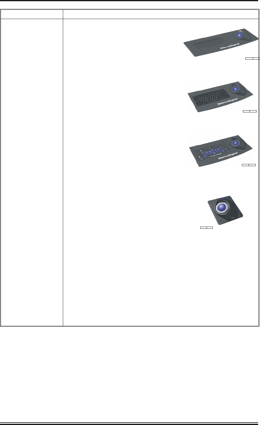
Function Parameters
Mechanical (cont) Remote Trackerball with Pencil tray MDD-A100:
Height: 90 mm
Width: 486 mm
Depth: 228 mm
Weight: 1.5 kg
Remote Keyboard/Trackerball MDD-A101:
Height: 90 mm
Width: 486 mm
Depth: 228 mm
Weight: 1.8 kg
MCI Panel/Trackerball MDD-A102:
Height: 90 mm
Width: 486 mm
Depth: 228 mm
Weight: 2.2 kg
Remote Trackerball MDD-A110:
Height: 82 mm
Width: 170 mm
Depth: 189 mm
Cooling: Fan re-circulated cooling
Electrostatic
damage: Provision for wrist strap point
Environmental: To IEC 60945 Ed 04
Ergonomic design to ISO
recommendations
Cables: Individually clamped at entry.
Cable entries to allow for bottom entry
Provision for earthing bolt
Page 1.34 Issue 5 (Jan 09)
KH2060-1
CD-7255 ISSUE 1
CD-7256 ISSUE 1
CD-7253 ISSUE 2
CD-7254 ISSUE 1

KH2060-2
SWITCHING ON AND OFF
CONTENTS
Para Page
Issue 5 (Jan 09) Page 2.1
KH2060-2
1 SWITCH ING ON 2.3
4 CON TROL FUNCTIONS 2.3
6 SWITCH ING OFF 2.4

THIS PAGE INTENTIONALLY BLANK
Page 2.2 Issue 5 (Jan 09)
KH2060-2
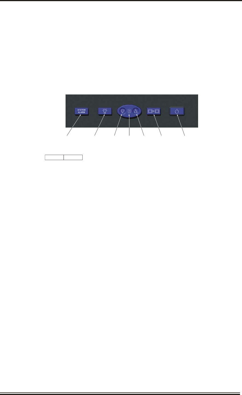
KH2060-2
SWITCHING ON AND OFF
SWITCH ING ON
1 Press the System ON/OFF button on the Visual Display Unit (located below the screen)
to switch the system on. The operating system will boot up and the Standby screen will be
shown. If necessary, using the Trackerball and Button Backlight and Screen Backlight
controls set up the required level of backlighting.
2 If the system does not start up, check the following:
(1) Check that the radar sensors are switched on, as follows:
(a) If a Drive Control Unit is fitted, ensure the key on the top of the unit is set to
ON. The MOTOR ON indicator will light indicating that power is applied
to the antenna.
(b) If a Transmitter Interface Unit (TIU) is fitted, ensure the ON/OFF switch on
top of the unit is set to ON.
(2) If a Radar Interswitch Unit (RIU) is fitted ensure the switch on the base of the unit
is set to ON (note that it is normally left in the ON position when the radar system
is not in use).
(3) Check that the ON/OFF switch on the Processor Unit is switched on (note that it
is normally left in the ON position when the radar system is not in use).
3 Refer to KH3200, bound in Section 2 of this manual, for the Radar operating procedures.
CON TROL FUNC TIONS
4 The Display Select control is only used on multi-function displays in an Integrated
Bridge System or Integrated Navigation System, and allows the user to view Processor
Units which have different functionality, e.g. Radar, ECDIS, Conning Display.
5 The System Alarm will be lit brightly in red and an audible alarm will sound if a system
fail is detected. Pressing the button acknowledges the alarm and silences the audible
alarm. A system alarm is initiated by the watchdog timer on the Processor Unit and indicates a
problem in the Processor Unit.
Issue 5 (Jan 09) Page 2.3
KH2060-2
SYSTEM
ALARM
TRACKERBALL
AND BUTTON
BACKLIGHT
SCREEN
BACKLIGHT
DISPLAY
SELECT
SYSTEM
ON/OFF
DOWN UP
CD-7406 ISSUE 1

SWITCH ING OFF
6 Under normal conditions the user should return to the Standby screen before switching
the system off. This leaves the Radar system in a suitable state to be switched on again
from the Visual Display Unit.
7 Press the System ON/OFF button on the visual display unit to set the unit to off.
8 The Processor Unit, RIU and radar sensors are normally left switched on, and should
only be switched off for maintenance purposes.
9 Refer to KH3200 for the shutdown procedure to return to the Standby screen.
Page 2.4 Issue 5 (Jan 09)
KH2060-2

KH2060-4
MAINTENANCE
CONTENTS
Para Page
ILLUSTRATIONS
Figure Page
Issue 5 (Jan 09) Page 4.1
KH2060-4
1 INTRODUCTION 4.3
3 PRE VEN TIVE MAIN TE NANCE 4.3
5 3 Monthly Checks - Clean or Re place Fan Filters 4.3
8 Performance Checks - Monthly or Be fore Leaving Port 4.4
11 DI AG NOS TIC MAIN TE NANCE 4.6
13 Single Point of Fail ure 4.9
17 Per for mance Check Deg ra da tion - Mag ne tron Trans ceiv ers 4.9
21 COR REC TIVE MAIN TE NANCE 4.10
22 Fuse Re place ment 4.10
28 Ra dar Sen sor Maintenance 4.12
34 Lifed Com po nents 4.12
38 Res to ration of Sys tem Con figuration in the event of Hard Disk Fail ure 4.13
1 Typical X-Band Tx/Rx Monitor Responses 4.5
2 Typical S-Band Tx/Rx Monitor Responses 4.5
3 MantaDigital Processor: Location of Fuses 4.11

THIS PAGE INTENTIONALLY BLANK
Page 4.2 Issue 5 (Jan 09)
KH2060-4

KH2060-4
MAINTENANCE
INTRODUCTION
1 This Chapter provides Maintenance information for the MantaDigital Radar displays.
The Chapter is divided into three parts
(1) Preventive Maintenance
(2) Diagnostic Maintenance
(3) Corrective Maintenance
2 The following paragraphs outline the basic maintenance and fault finding procedures
which can be implemented by the user. The fault finding/repair philosophy is limited to
checking cable connections, changing fuses and checking equipment performance.
PRE VEN TIVE MAIN TE NANCE
3 Preventive Maintenance comprises keeping the equipment clean, particularly the screen,
console cabinets and fan exhaust filters, and carrying out performance checks. External
surfaces (but not screens) should be cleaned with a soft, non-abrasive cloth, moistened in a mild
soap solution.
4 Screens are to be checked and cleaned regularly, using light pressure an approved screen
cleaner. Under no circumstances use detergents as these will damage the screens.
3 Monthly Checks - Clean or Re place Fan Filters
5 Fan filters must be checked and cleaned every 3 months. To check and clean fan filters,
ensure that the power supplies to the processor are isolated. Open the front panel and
slide the fan filters up and remove. Inspect and if necessary clean as described in the next
paragraph. Replace filters, close front panel and restore power supplies.
6 To clean a fan filter, vacuum clean the dust from it. If it is not possible to satisfactorily
clean the filter, fit a new filter, Kelvin Hughes Part Number MDP-1039.
7 Check that all connections especially earth bonding are secure and in their correct
positions.
Issue 5 (Jan 09) Page 4.3
KH2060-4
WARNING
LETHAL VOLT AGES ARE PRES ENT IN SIDE THE EQUIPMENT.
ALL COR RECTIVE MAINTENANCE MUST BE IM PLE MENTED WITH THE
POWER SUP PLIES SWITCHED OFF

Performance Checks - Monthly or Be fore Leav ing Port
8 The performance of the magnetron, transmission line and receiver circuits is checked by
carrying out a performance monitor check.
9 The performance monitors consist of:
(1) Transmission Monitor - comprises a monitor arm fitted to the outer case of the
scanner unit. The monitor arm neon is ionised as the antenna passes over the arm,
and a ‘plume’ is shown on the screen.
(2) Receiver Monitor - uses a resonant cavity (X-band) or signal source (S-band) to
generate a reference signal. The signal is shown as 'fingers' on the screen for an
S-band transceiver and as a 'sun' on the screen for an X-band transceiver.
10 To carry out the performance monitor check, proceed as follows:
(1) Switch the visual display unit power to ON.
(2) After the Tx warm-up period, go to transmit in either single or dual radar mode.
(3) Select the 12 nautical mile range. Ensure the radar image is correctly tuned.
(4) Left-click on the on-screen PM button.
(5) Using the VRM facility, measure the length of the 'plume'. Record the length of
the 'plume' in the users record under the PERFORMANCE MONITOR heading
in the TX.... nm. This data must be recorded as it will be used to identify
degradation in performance.
(6) Select 1.5 nautical mile range (X-band) or leave on 12 nautical mile range
(S-band) and PERF.MON, (this on-screen button is located at the top left-hand
corner of the radar operational area).
(7) By using the VRM facility, measure the length of the radar 'fingers' or diameter of
the 'sun' on the screen.
(8) Record the length of the 'fingers' or diameter of the 'sun' in the users record under
the PERFORMANCE MONITOR heading in the RX.... nm. This data must be
recorded as it will be used to identify degradation in performance.
(9) Compare the results with those previously recorded. If there is a significant
degradation since the last reading, refer to the Performance Check Degradation
paragraphs below.
Page 4.4 Issue 5 (Jan 09)
KH2060-4
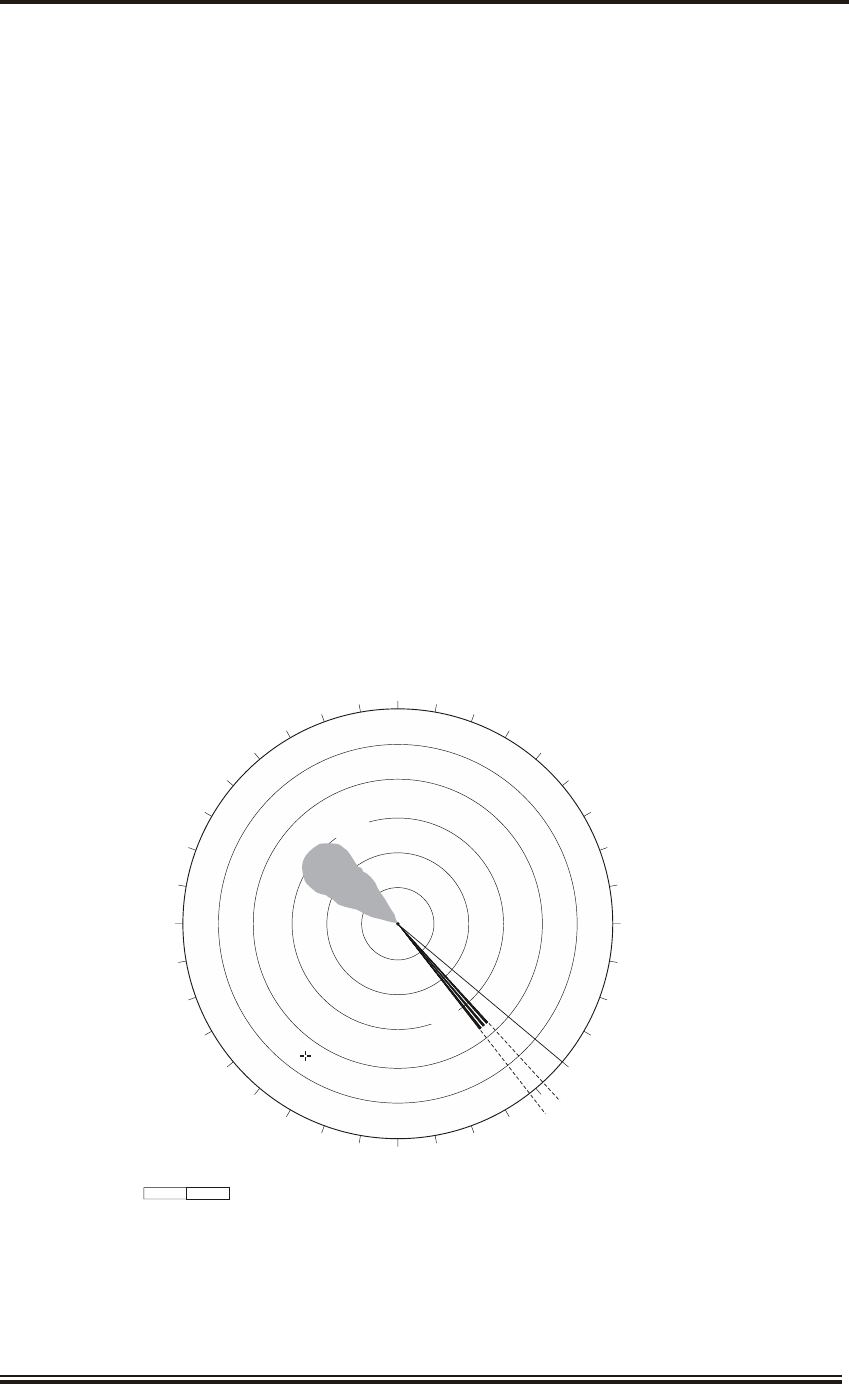
Issue 5 (Jan 09) Page 4.5
KH2060-4
INFORMATION TO FOLLOW
Figure 1 - Typical X-Band Tx/Rx Monitor Responses
000
180
090
270
100
110
120
130
150
160
170
190
200
210
220
230
240
250
260
280
290
300
310
320
330
340
350 010
020
030
040
050
060
070
080
140
CD-7039 ISSUE 3
Tx MON
Rx MON
8°to 13° FROM HEADING LINE
HEADING LINE
Figure 2 - Typical S-Band Tx/Rx Monitor Responses

DI AG NOS TIC MAIN TE NANCE
11 These paragraphs provides diagnostic maintenance procedures which the user may follow to
restore normal operation. If normal operation cannot be restored, do not attempt to check
inside any unit. Any repair work is best left to a qualified technician.
12 Warning messages are shown in the bottom right hand corner of the screen.
TABLE 1 - TROUBLESHOOTING
PROBLEM CAUSE REMEDY
Picture not updated or picture
freeze-up. This is indicated by the
UTC time not changing
Video freeze-up Turn the power off and on again to
restore normal operation.
If normal operation is not restored
call the Kelvin Hughes Service
Control Centre or the agent.
Range changed but radar picture
does not change
Video freeze-up Try clicking on the range button
several times to change the range.
If that does not work, try turning the
power off and on again to restore
normal operation.
If normal operation is not restored
call the Kelvin Hughes Service
Control Centre or the agent.
Failure Messages - Kelvin Hughes
magnetron transceiver
No Sync
No Video
No Azimuth
No Heading Line
The sync pulses from the transceiver
are not being detected at the radar
display
The radar video from the transceiver
is not being detected at the radar
display
The azimuth pulses from the
transceiver are not being detected at
the radar display
The heading line pulses from the
transceiver are not being detected at
the radar display
One or more of these messages may
appear in the alarm box of the screen
if the signals are missing. Note the
messages that are shown, as this
information will assist the service
engineer.
Refer to the relevant ship's manual for
the sensor for further troubleshooting
procedures.
If normal operation cannot be
restored call the Kelvin Hughes
Service Control Centre or the agent.
Page 4.6 Issue 5 (Jan 09)
KH2060-4

PROBLEM CAUSE REMEDY
Failure Messages - Kelvin Hughes
SharpEyeTM transceiver
No Sync
No Video
No Azimuth
No Heading Line
Receiver Sensitivity Low
Antenna VSWR High
RF Power Low
PLO Lock
Synth Lock
Transmitter Over-temperature
The sync pulses from the transceiver
are not being detected at the radar
display
The radar video from the transceiver
is not being detected at the radar
display
The azimuth pulses from the
transceiver are not being detected at
the radar display
The heading line pulses from the
transceiver are not being detected at
the radar display
Indicates that the minimum detectable
signal is below a preset threshold
Indicates a mismatch in the VSWR
into the antenna
The RF power output from the
transceiver has fallen below 100 W
Indicates hardware fault in phase
locked oscillator
Indicates hardware fault in frequency
synthesiser
The temperature of the RF power
transistors is high
One or more of these messages may
appear in the alarm box of the screen
if the signals are missing. Note the
messages that are shown, as this
information will assist the service
engineer.
The SharpEyeTM transceiver will
either enter Degraded mode, in which
case the transceiver will continue to
operate at reduced power with a loss
of performance or functionality, or
Fault mode in which case the
transceiver will shut down.
Refer to the relevant ship's manual for
the transceiver for further
troubleshooting procedures.
Call the Kelvin Hughes Service
Control Centre or the agent.
Issue 5 (Jan 09) Page 4.7
KH2060-4

PROBLEM CAUSE REMEDY
Failure messages - external
equipment, e.g.
Gyro Fail
Log Fail
GPS/EPFS Fail
Depth Fail
The gyro input has not been detected.
The log input has not been detected.
The GPS or EPFS input has not been
detected.
The depth sensor has not been
detected.
One or more of these messages may
appear in the alarm box of the screen
if the signals are missing. Note the
messages that are shown, as this
information will assist the service
engineer.
Check the reading on the associated
gyro unit. If a gyro repeater is fitted,
check that the repeater is on and
reading accurately.
Check the reading on the associated
log unit. If a log repeater is fitted,
check that the repeater is on and
reading accurately.
Check the position information from
the GPS/EPFS is accurate.
If the position sensing equipment is
provided with a switch to
enable/disable serially transmitted
data, check that the message type
GGA or GLL is enabled.
Check that the position sensor is set
to NMEA 0183.
Check the reading on the associated
echo sounder.
If an echo sounder repeater is fitted,
check that the repeater is on and is
reading accurately.
Call the Kelvin Hughes Service
Control Centre or the agent.
Poor discrimination in range Sea anti-clutter control not set
correctly
Adjust SEA anti-clutter control
Tuning adjusted correctly, but poor
sensitivity
Dirt on antenna radiator face,
water in antenna or waveguide,
low magnetron,
receiver failure
Carry out a performance monitor
check. If the results shows
degradation there is probably a fault
in the transceiver.
If the performance monitor is OK,
clean the antenna radiator face. Refer
to the relevant ship's manual for the
transceiver for the procedure.
Target Tracking target not tracked
correctly
Poor definition of targets in sea
clutter
Adjust the SEA anti-clutter and RAIN
anti-clutter controls to improve target
definition.
Page 4.8 Issue 5 (Jan 09)
KH2060-4

Single Point of Fail ure
13 In systems with multiple Radar Sensors and Radar Displays, the Radar Sensors are
interfaced with the Radar Displays via a Radar Interswitch Unit (RIU). The RIU is the
critical point in the configuration as all signals are routed via the RIU.
14 If any one of the Radar Sensors or Radar Displays fails, the system will remain
operational with reduced capability, i.e. loss of one Radar Sensor or one Radar Display.
15 If the RIU fails, each Radar Sensor will be allocated to a specific Radar Display (this is
carried out in hardware and is determined on installation. The allocation cannot be
changed by the user. Radar Sensor 1 is assigned to Radar Display 1, Radar Sensor 2 is assigned to
radar Display 2 etc.). This limits each user position (Radar Display) to its allocated Radar
Sensor, thus providing operation with reduced capability. An alarm is generated to warn the user
that the radar sensor will revert to the default radar sensor assigned in the event of RIU failure.
16 In systems with a single Radar Sensor and Radar Display, failure of any critical unit may
prevent the system from operating. There is no means of reconfiguring the system to
provide some level of functionality.
Per for mance Check Deg ra da tion - Mag ne tron Trans ceiv ers
17 If the performance of the radar has deteriorated, and there are no failure messages, carry
out the performance monitor check detailed above and compare the readings with those
documented on installation and at the last routine check.
18 If the Tx Monitor Plume is <50% of the original logged value (the reading taken at
installation), the Rx Monitor Sun (X-band) is <80% of the original logged value or the Rx
Monitor Fingers (S-band) is <50% of the original logged value (the reading taken at installation)
a fault is present in the radar sensor. Lower levels of degradation may also cause performance
problems.
19 Note the following:
(1) Whether the degradation is in the 'plume' or the 'fingers'/'sun' or both.
(2) If there is a significant degradation in the 'plume', the transmitter power has
reduced. The most likely cause of this is aging of the magnetron, and this will
need to be replaced. Note that magnetrons are lifed items and as soon as
significant degradation is detected, a visit to the ship by a service engineer should
be arranged to check the transceiver, and if necessary replace the magnetron.
(3) If there is significant degradation in the 'fingers' or 'sun', there is likely to be a
fault in the receiver circuits.
20 Contact the Kelvin Hughes Service Control Centre or the agent with full details of the
degradation recorded to obtain advice.
Issue 5 (Jan 09) Page 4.9
KH2060-4

NOTE: The magnetron in the transceiver is a lifed item, and should be replaced when the
running hours approach the life of the magnetron. Refer to the relevant radar sensor
Ship's Manual for details of life of a specific magnetron and for the procedures to replace
the magnetron.
COR REC TIVE MAIN TE NANCE
21 Cor rec tive main te nance should only be im ple mented by qual i fied per son nel. Cor rec tive
maintenance for this equip ment is lim ited to the re placement of Fuses in the
MantaDigital Processor.
Fuse Re place ment
22 The locations of the fuses in the MantaDigital Processor Unit are shown in Figure 3. The
fuses vary according to the particular processor unit but all fuse positions are shown in
the figure.
(1) Ship’s mains supply. Two fuses on Power Supply Assembly.
Fuse Anti-Surge 10 A 250 V. Kelvin Hughes Part No. 45-615-162-50.
(2) +12V supply on FSD-A178 PCB.
Fuse Anti-Surge 3.15 A. Kelvin Hughes Part No. 45-615-161-30.
23 Switch off the power supply to the Processor unit.
24 Gain access to the fuses, as follows:
(1) Open the front cover of the Processor unit.
(2) The mains fuses are located on the power supply assembly behind the drop down
mounting plate. Release the plate by lift the two, lever fasteners and lowering the
plate forwards, refer to Figure 3.
(3) The other fuses are located on the PCB(s) on the front of the mounting plate, see
Figure 1.
25 Fit the new fuse and secure it in the fuse holder.
Page 4.10 Issue 5 (Jan 09)
KH2060-4
CAU TION
This equip ment con tains Elec trostatic Sen sitive de vices. To pre vent dam age to equip -
ment; when im ple ment ing Cor rec tive Main te nance pro ce dures en sure that an earthing
strap is used to con nect the maintainer to the earth stud.
WARNING
LETHAL VOLT AGES ARE PRES ENT IN SIDE THE EQUIPMENT.
ALL COR RECTIVE MAINTENANCE MUST BE IM PLE MENTED WITH THE
POWER SUP PLIES SWITCHED OFF
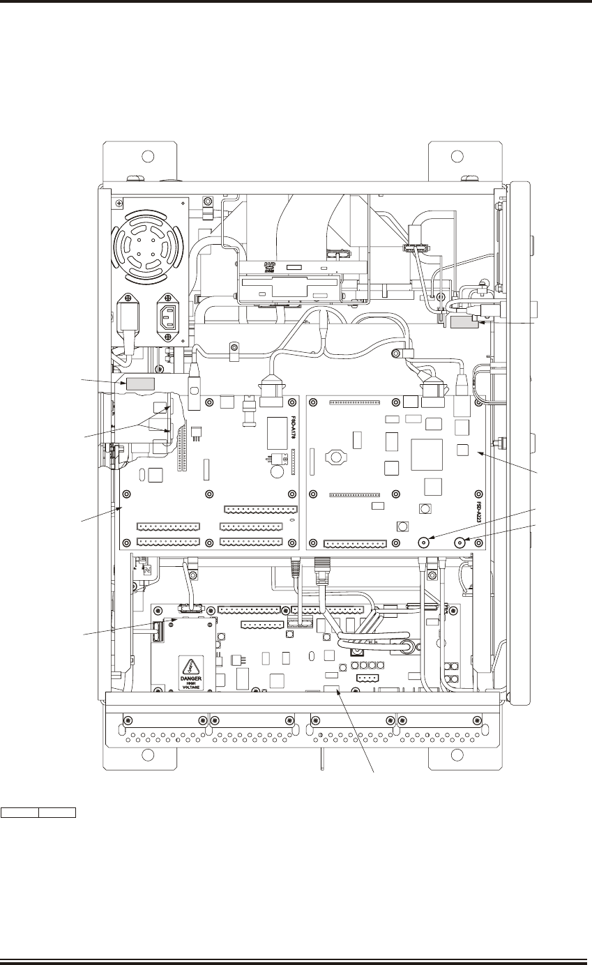
26 Close the front cover.
27 Restore the power supply to the processor and check that the system is operating
correctly.
Issue 5 (Jan 09) Page 4.11
KH2060-4
SERIAL INPUT PCB
FSD-A178
DISPLAY INTERFACE PCB
FSD-A179
USB DONGLE
CD-7409 ISSUE 1
MANTA RADAR
INTERFACE PCB
FSD-A223
SK3 SYNC
SK4 VIDEO
FS1
FS2
CUTAWAY SHOWING
MAINS FUSES ON
POWER SUPPLY PLATE
RELEASE LEVER
RELEASE LEVER
PL18 PL7
PL2
PL3
SK4
PL1
SK2
K5
PL5
PL4
PL1
PL2
PL3
SK5
SK2 PL18 SK1
PL6
PL1
SK6
SK3 SK4
SK1 PL9
PL6
PL8
SK5
Figure 3 - MantaDigital Processor: Location of Fuses

Ra dar Sen sor Maintenance
28 Radar Sensor maintenance is provided in the Ship's Manual for the radar sensor. The only
information provided here is general information on working aloft and information on
lifed components.
WARNING
ANTENNA RO TATION: BE FORE MAINTENANCE TO THE TURN ING
MECHANISM TAKES PLACE, DIS ABLE ANTENNA RO TATION.
29 When work ing aloft, en sure that it is brought to the at ten tion of some one in au thority at
deck or at ground level and that suit ably placed warning no tices are posted warn ing that
work aloft is in prog ress. En sure that the means of ac cess aloft is se cure and be ware of wet or
slippery lad der rungs and work ing ar eas.
30 When work ing on or near a ra dar antenna and other mov ing or RF ra diating equip ment,
ensure that it is switched off and that the fuses have been re moved and re tained.
31 If the Radar Sensor is fitted with a Drive Control Unit, ensure the keyswitch on the top of
the unit is set to OFF and the key is withdrawn before going aloft. Note that the key is
retained when set to the ON position and cannot be removed. Switching the Drive Control Unit to
OFF and removing the key ensures the antenna cannot rotate.
32 On radar sensors fitted with a Transmitter Interface Unit, ensure the power On/Off
switch is set to OFF and if possible, remove the fuses. This unit does not have a
keyswitch.
33 Refer to the Ship's Manual for the Radar Sensor for further details of man aloft safety
procedures.
Lifed Com po nents
34 The conventional Radar Sensor contains a magnetron, which is a lifed item. Refer to the
Ship's Manual for the Radar Sensor for details of the magnetron and its replacement
procedure. The magnetron performance is checked using the performance monitor as described
in this chapter.
35 The SharpEyeTM Radar Sensor has no lifed items.
36 The backlights in the LCD display have a nominal life of up to 50,000 operating hours.
Therefore, the Visual Display Unit should be switched off when not in use to maximise
the life of the backlights. Backlight replacement is a specialist task and must be undertaken by a
Kelvin Hughes service engineer or approved agent.
37 The fan filters need to be replaced when they can no longer be cleaned. Refer to the
Preventive Maintenance for details.
Page 4.12 Issue 5 (Jan 09)
KH2060-4

Restoration of System Con fig uration in the event of Hard Disk Fail ure
38 On installation the system configuration data is stored on the hard disk. A back-up of this
data is taken after installation. This back-up must be stored so that it can be used to restore
the system in event of hard disk failure. The menus used to backup and restore the configuration
data are password protected and are not available to the user.
39 Map and route data is also stored on the hard disk. The user should take regular backups
to removable media (memory stick) for restoration in the event of hard disk failure.
40 Therefore, in the event of hard disk failure the configuration data is restored from:
(1) The back-up data taken by the installer after installation is complete, which
allows the configuration data to be restored.
(2) Map and Route data taken by the user at regular intervals, which allows the
current maps and routes to be restored.
41 The data is restored from the removable media onto the new hard disk. Hard disk
replacement and restoration of data must be undertaken by a Kelvin Hughes service
engineer or approved agent.
NOTE: Data is restored from Set-Up Mode. This menu is password protected and is only
available to authorised personnel. Refer to Ship's Manual KH2061 for further
information.
Issue 5 (Jan 09) Page 4.13
KH2060-4

THIS PAGE INTENTIONALLY BLANK
Page 4.14 Issue 5 (Jan 09)
KH2060-4