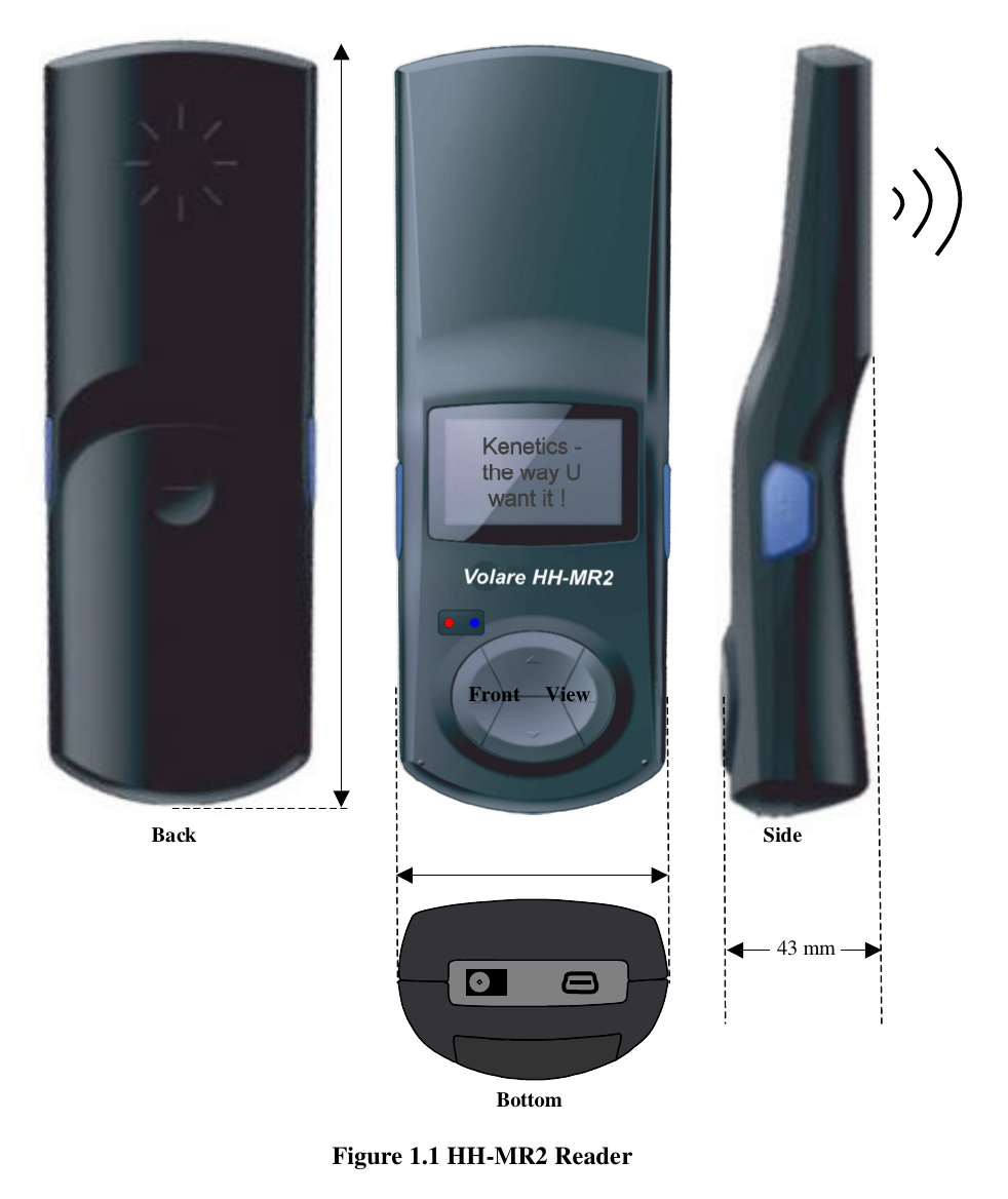
Kenetics Innovations HH-MR2 RFID READER User Manual
Kenetics Innovations Pte Ltd RFID READER
UserManual.wiki
>
Kenetics Innovations
>
HH MR2 User Manual
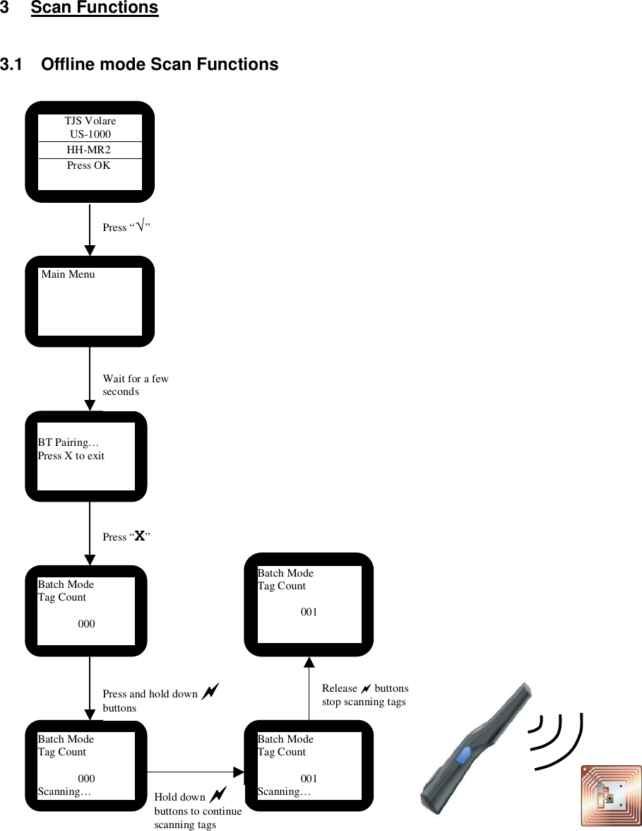
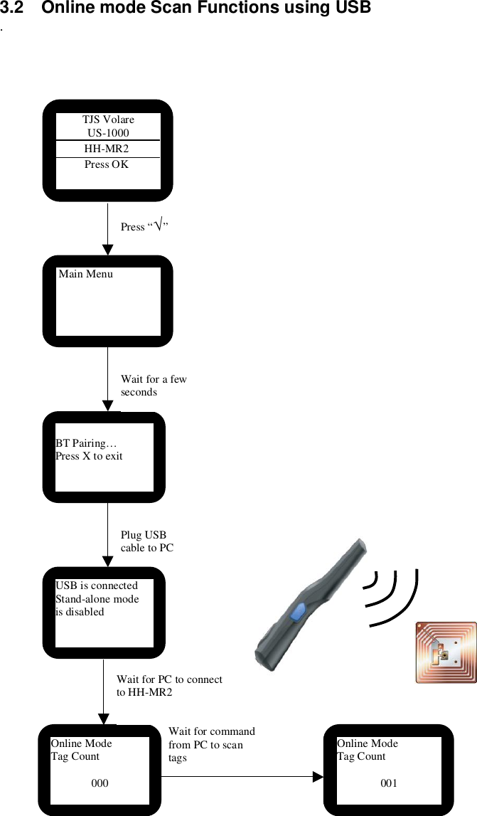
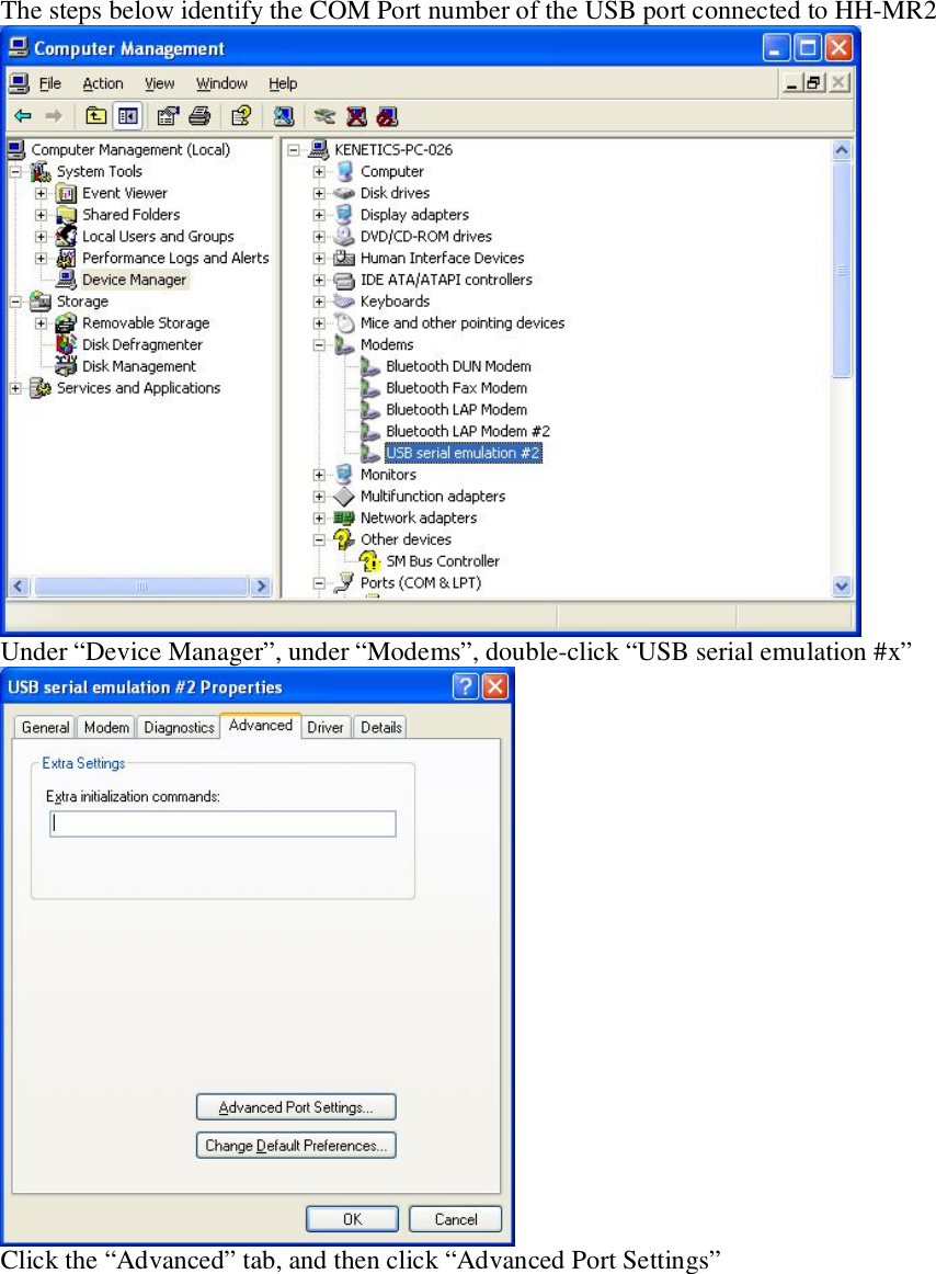
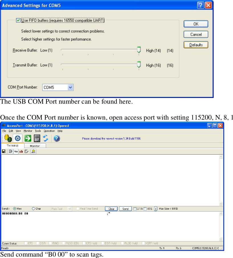
User Manual
Navigation menu
Upload a User Manual
Namespaces
Wiki Guide
HTML
PDF
Info
Views
User Manual
Discussion / Help
Navigation