Kenmore Elite 11060056990 User Manual ELECTRIC DRYER Manuals And Guides L0704195
KENMORE ELITE Residential Dryer Manual L0704195 KENMORE ELITE Residential Dryer Owner's Manual, KENMORE ELITE Residential Dryer installation guides
User Manual: Kenmore Elite 11060056990 11060056990 KENMORE ELITE ELECTRIC DRYER - Manuals and Guides View the owners manual for your KENMORE ELITE ELECTRIC DRYER #11060056990. Home:Laundry & Garment Care Parts:Kenmore Elite Parts:Kenmore Elite ELECTRIC DRYER Manual
Open the PDF directly: View PDF ![]() .
.
Page Count: 51
Owner's Manual and
Installation Instructions
EL I T E
SENSOR SMART TM
27-Inch Wide
ELECTRIC DRYERS
iMPORTANT:
Read and follow air safety
and operating instructions
before first use of this product.
Sears, Roebuck and Co., Hoffman Estates, mL60179 U.S.A.
www.sears.com
}_iiiiiiiJiii/i
8283156A PRINTED IN U.S.A. 9/99
BEFORE USINGYOUR NEW DRYER
KENMORE ELITE TM DRYER WARRANTY
DRYER SAFETY
INSTALLATION INSTRUCTIONS
OPERATING YOUR DRYER
LAUNDRY TIPS
CARING FORYOUR DRYER
TROUBLESHOOTING
SEARS MAINTENANCE AGREEMENT
2
3
4
6
30
41
43
47
49
Please read this manual It will help
you install and operate your new
Kenmore ELITE TM dryer in the most
economical way.
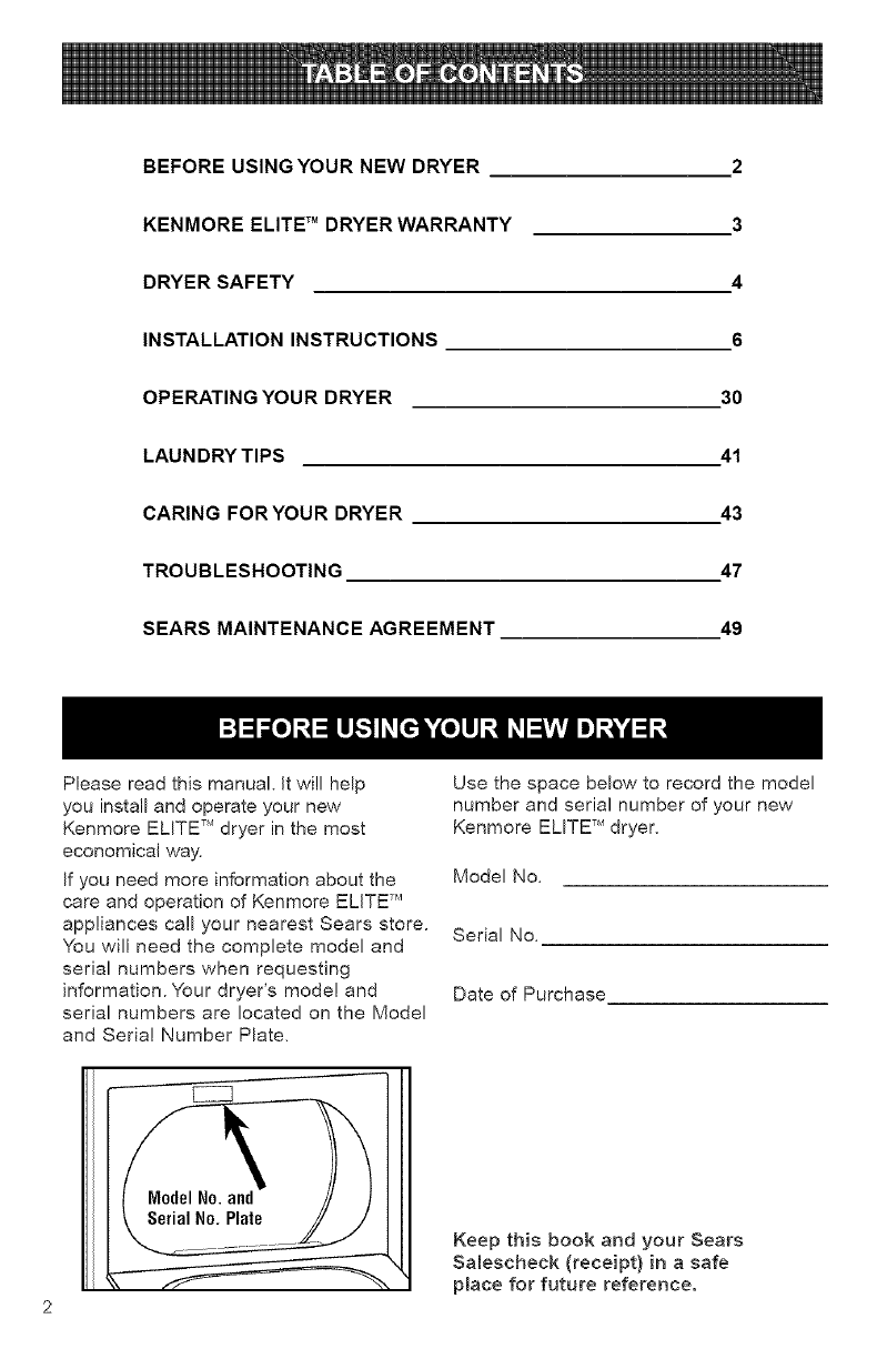
If you need more information about the
care and operation of Kenmore ELITE TM
appliances call your nearest Sears store.
You will need the complete model and
serial numbers when requesting
information. Your dryer's model and
serial numbers are located on the Model
and Serial Number Plate,
Use the space below to record the model
number and serial number of your new
Kenmore ELITE TM dryer,
Model No,
Serial No,
Date of Purchase
Keep this book and your Sears
Salescheck (receipt) in a safe
place for future reference.
Full One Year Warranty on
Mechanical and Electrical Parts
For one year from the date of purchase,
if this dryer is installed and operated
according to the instructions in this
manual, Sears will repair or replace any
of its mechanical or electrical parts if they
are defective in material or workmanship.
NOTE: Exhausting your dryer with
a plastic vent may void this warranty.
Pages 24-28 of this manual describe
the complete exhaust requirements
for this dryer.
Limited 2-Year Warranty on
SENSOR SMART TM Control Board
For two years from the date of purchase,
Sears will replace the SENSOR SMART TM
control board if it is defective in material or
workmanship. You will be charged for labor
after the first year.
Warranty Restriction
If the dryer is subjected to other than
private family use, all warranty coverage is
effective for only 90 days.
Warranty Service
Warranty service is available by contacting
your nearest Sears Service Center in the
United States.
This warranty applies only while this dryer
is in use in the United States.
This warranty gives you specific legal
rights, and you may also have other rights
which vary from state to state.
Sears, Roebuck and Co., Dept. 817WA,
Hoffman Estates, IL 60179.
For Sears Warranty information or to contact a
Sears Service Center, catl 1-80O-4-MY-HOME
(1-800-469-4663)
Your safety and the safety of others is very important.
We have provided many important safety messages in this manual and on
your appliance. Always read and obey all safety messages.
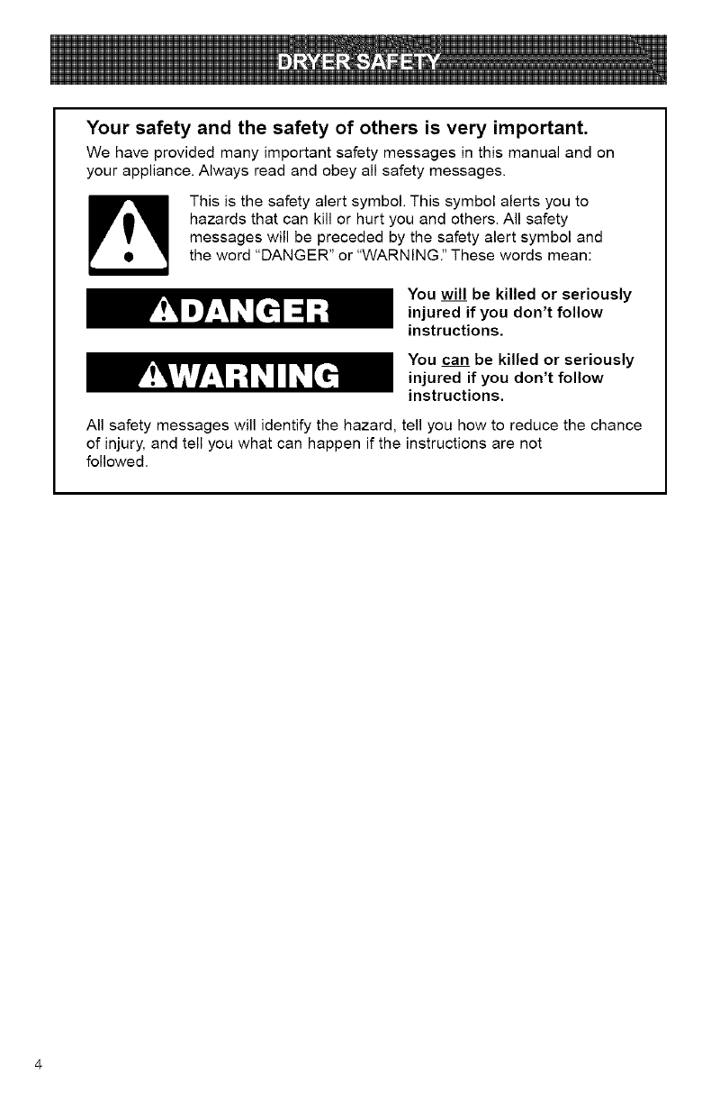
This is the safety alert symbol. This symbol alerts you to
hazards that can kill or hurt you and others. All safety
messages will be preceded by the safety alert symbol and
the word "DANGER" or "WARNING." These words mean:
You wil__lbe killed or seriously
injured if you don't follow
instructions.
You can be killed or seriously
injured if you don't follow
instructions.
All safety messages will identify the hazard, tell you how to reduce the chance
of injury, and tell you what can happen if the instructions are not
followed.
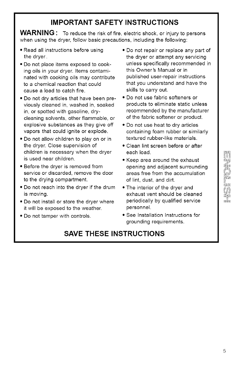
IMPORTANT SAFETY INSTRUCTIONS
WARNING : To reduce the risk of fire, electric shock, or injury to persons
when using the dryer, follow basic precautions, including the following:
•Read all instructions before using
the dryer.
• Do not place items exposed to cook-
ing oils in your dryer. Items contami-
nated with cooking oils may contribute
to a chemical reaction that could
cause a load to catch fire.
• Do not dry articles that have been pre-
viously cleaned in, washed in, soaked
in, or spotted with gasoline, dry-
cleaning solvents, other flammable, or
explosive substances as they give off
vapors that could ignite or explode.
• Do not allow children to play on or in
the dryer. Close supervision of
children is necessary when the dryer
is used near children.
• Before the dryer is removed from
service or discarded, remove the door
to the drying compartment.
• Do not reach into the dryer if the drum
is moving.
• Do not install or store the dryer where
it will be exposed to the weather.
• Do not tamper with controls.
• Do not repair or replace any part of
the dryer or attempt any servicing
unless specifically recommended in
this Owner's Manual or in
published user-repair instructions
that you understand and have the
skills to carry out.
• Do not use fabric softeners or
products to eliminate static unless
recommended by the manufacturer
of the fabric softener or product.
• Do not use heat to dry articles
containing foam rubber or similarly
textured rubber-like materials.
• Clean lint screen before or after
each load.
• Keep area around the exhaust
opening and adjacent surrounding
areas free from the accumulation
of lint, dust, and dirt.
• The interior of the dryer and
exhaust vent should be cleaned
periodically by qualified service
personnel.
• See Installation Instructions for
grounding requirements.
SAVE THESE INSTRUCTIONS
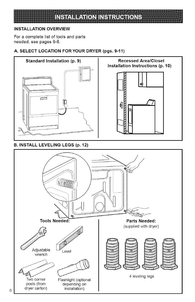
INSTALLATION OVERVIEW
For a complete list of tools and parts
needed, see pages 6-8.
A. SELECT LOCATION FORYOUR DRYER (pgs. 9-11)
Standard Installation (p. 9) Recessed Area/Closet
Installation Instructions (p. 10)
B. INSTALL LEVELING LEGS (p. 12)
Tools Needed:
wrench
Two corner Flashlight (optional
posts (from depending on
dryer carton) installation)
Parts Needed:
(supplied with dryer)
4 leveling legs
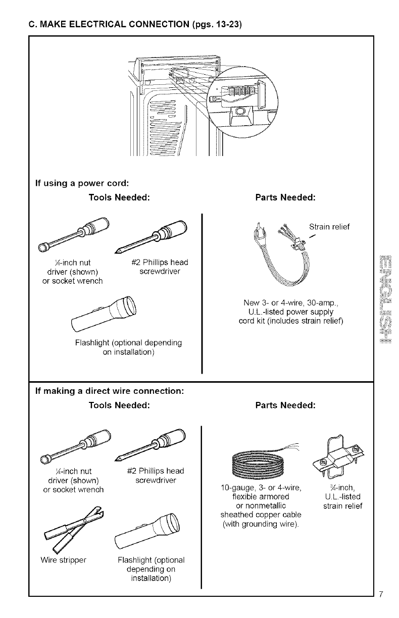
C.MAKE ELECTRICAL CONNECTION (pgs. 13-23)
If using apower cord:
Tools Needed:
_-inch nut #2 Phillips head
driver (shown) screwdriver
or socket wrench
Flashlight (optional depending
on installation)
Parts Needed:
New 3- or 4-wire, 30-amp.,
U.L.-listed power supply
cord kit (includes strain relief)
If making a direct wire connection:
Tools Needed: Parts Needed:
_-inch nut #2 Phillips head
driver (shown) screwdriver
or socket wrench
Wire stripper Flashlight (optional
depending on
installation)
10-gauge, 3- or 4-wire,
flexible armored
or nonmetallic
sheathed copper cable
(with grounding wire).
_-inch,
U.L.-listed
strain relief
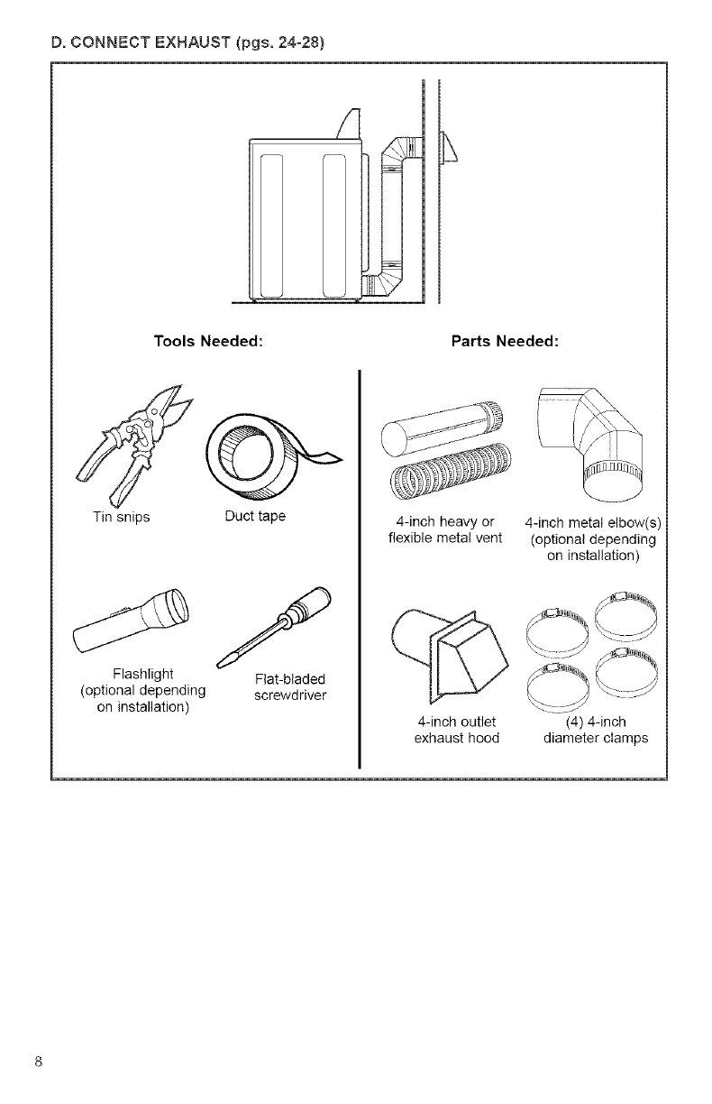
D.CONNECTEXHAUST(pgs.24=28)
t
Tools Needed: Parts Needed:
Tin snips Duct tape
Flashlight
(optional depending
on installation)
Flat-bladed
screwd river
4-inch heavy or
flexible metal vent
4-inch outlet
exhaust hood
4-inch metal elbow(s)
(optional depending
on installation)
(4) 4-inch
diameter clamps
A. SELECT LOCATION FOR
YOUR DRYER
F te_mft0_,'_i t,I_ i[3 _t •
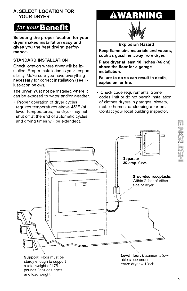
Selecting the proper location for your
dryer makes installation easy and
gives you the best drying perfor-
mance.
STANDARD INSTALLATION
Check location where dryer will be in-
stalled. Proper installation is your respon-
sibility. Make sure you have everything
necessary for correct installation (see il-
lustration below).
The dryer must not be installed where it
can be exposed to water and/or weather.
• Proper operation of dryer cycles
requires temperatures above 45°F (at
lower temperatures, the dryer may not
shut off at the end of automatic cycles
and drying times will be extended).
Explosion Hazard
Keep flammable materials and vapors,
such as gasoline, away from dryer.
Place dryer at least 18 inches (46 cm)
above the floor for a garage
installation.
Failure to do so can result in death,
explosion, or fire.
Check code requirements. Some
codes limit or do not permit installation
of clothes dryers in garages, closets,
mobile homes, or sleeping quarters.
Contact your local building inspector.
__ Separate
) I
i ] .......
_de of df_e_
Support: Floor must be Level floor: Maximum allow-
sturdy enough to support able slope under
a total weight of 175 entire dryer - 1 inch.
pounds (includes dryer
and load weight).
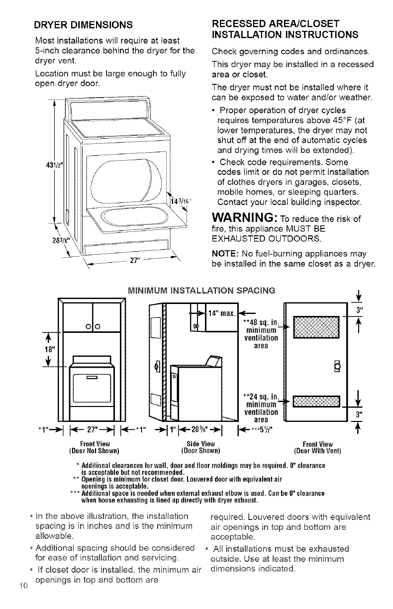
DRYER DIMENSIONS
Most installations will require at least
5-inch clearance behind the dryer for the
dryer vent.
Location must be large enough to fully
open dryer door.
283/8 'l
RECESSED AREA/CLOSET
INSTALLATION INSTRUCTIONS
Check governing codes and ordinances.
This dryer may be installed in a recessed
area or closet.
The dryer must not be installed where it
can be exposed to water and/or weather.
• Proper operation of dryer cycles
requires temperatures above 45°F (at
lower temperatures, the dryer may not
shut off at the end of automatic cycles
and drying times will be extended).
• Check code requirements. Some
codes limit or do not permit installation
of clothes dryers in garages, closets,
mobile homes, or sleeping quarters.
Contact your local building inspector.
WARNING: To reduce the risk of
fire, this appliance MUST BE
EXHAUSTED OUTDOORS.
NOTE: No fuel-burning appliances may
be installed in the same closet as a dryer.
10
-1--
18"
÷
* 1"--'_
FrontView
(DoorNotShown)
MBNIMUM iNSTALLATION SPACING
**48sq.in.
minimum-
ventilation
area
**24sq.in.
minimum-
ventilation
area
_- **.51/2"
3"
3"
FrontView
(DoorWithVent)
* Additional clearances lor wall, doorand floor moldings may be required. 0" clearance
is acceptable but notrecommended.
** Openingis minimum lor closet door. Louvered doorwith equivalent air
openings is acceptable.
*** Additional spaoe is needed when external exhaust elbow is used. Can be 0" clearance
when houseexhausting is lined up directlywith dryer exhaust.
*In the above illustration, the installation required. Louvered doors with equivalent
spacing is in inches and is the minimum air openings in top and bottom are
allowable, acceptable.
*Additional spacing should be considered • Al! installations must be exhausted
for ease of installation and servicing, outside. Use at least the minimum
*If closet door is installed, the minimum air dimensions indicated.
openings in top and bottom are
MOBILE HOME EXHAUST
REQUIREMENTS
The dryer must not be installed where
it can be exposed to water and/or
weather. Proper operation of dryer cycles
requires temperatures above 45°F (at
lower temperatures, the dryer may not
shut off at the end of automatic cycles
and drying times win be extended).
This dryer is suitable for mobile home
installations. The installation must
conform to the Manufactured Home Con-
struction and Safety Standard, Title 24
CFR, Part 3280 (formerly the Federal
Standard for Mobile Homes Construction
and Safety, Title 24, HUD Part 280).
Use at least the minimum spacings as
described on page 10. This will ensure
an adequate clearance for service and
operation.
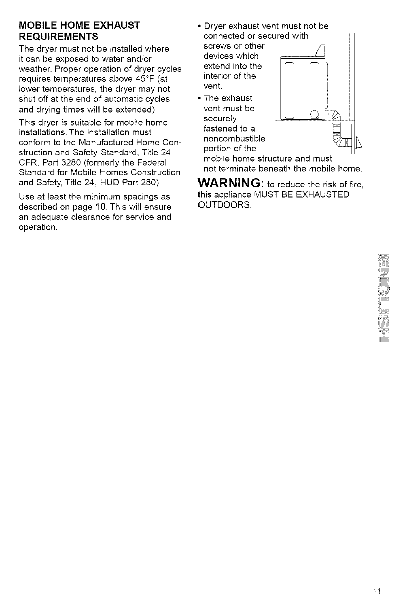
• Dryer exhaust vent must not be
connected or secured with
screws or other
devices which
extend into the
interior of the
vent.
• The exhaust
vent must be
securely . . .
fastened to a _-
noncombustible
portion of the
mobile home structure and must
not terminate beneath the mobile home.
WARNING: to reduce the risk of fire,
this appliance MUST BE EXHAUSTED
OUTDOORS.
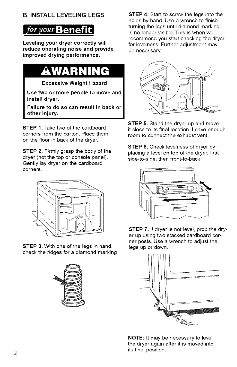
B. INSTALL LEVELING LEGS
Leveling your dryer correctly will
reduce operating noise and provide
improved drying performance.
STEP 4. Start to screw the legs into the
holes by hand. Use a wrench to finish
turning the legs until diamond marking
is no longer visible. This is when we
recommend you start checking the dryer
for levelness. Further adjustment may
be necessary.
!
Excessive Weight Hazard |
Use two or more people to move and
install dryer. I
Failure to do so can result in back or I
other injury. I
STEP 1. Take two of the cardboard
corners from the carton. Place them
on the floor in back of the dryer.
STEP 2. Firmly grasp the body of the
dryer (not the top or console panel).
Gently lay dryer on the cardboard
corners.
STEP 3. With one of the legs in hand,
check the ridges for a diamond marking.
STEP 5. Stand the dryer up and move
it close to its final location. Leave enough
room to connect the exhaust vent.
STEP 6. Check levelness of dryer by
placing a level on top of the dryer, first
side-to-side; then front-to-back.
STEP 7. If dryer is not level, prop the dry-
er up using two stacked cardboard cor-
ner posts. Use a wrench to adjust the
legs up or down.
I
12
NOTE: It may be necessary to level
the dryer again after it is moved into
its final position.
C.MAKE ELECTRICAL
CONNECTION
It is your responsibility:
• To contact a qualified electrical installer.
• To assure that the electrical installation
is adequate and in conformance with
the National Electrical Code, ANSI/NFPA
70 - latest edition and all local codes
and ordinances.
Copies of the code standards listed above
may be obtained from:
National Fire Protection Association
Batterymarch Park
Quincy, Massachusetts 02269
ELECTRICAL REQUIREMENTS
The proper electrical connection
ensures an installation that
meets local code requirements.
A three-wire or four-wire, single
phase, 120/240-volt, 60-Hz., AC-only,
electrical supply (or three-wire or
four-wire, 120/208-volt if specified
on serial/rating plate) is required on a
separate 30-ampere circuit, fused on both
sides of the line. A time-delay fuse or cir-
cuit breaker is recommended.
This dryer is manufactured with the
3-wire, frame-grounding conductor
connected to the NEUTRAL (white or
center) of the wiring harness of the
terminal block. Do not have a fuse in
the neutral or grounding circuit. A fuse
in the neutral or grounding circuit could
result in an electrical shock.
Use a 4-conductor cord when the
dryer is installed in a mobile home or
an area where local codes do not
permit grounding through the neutral.
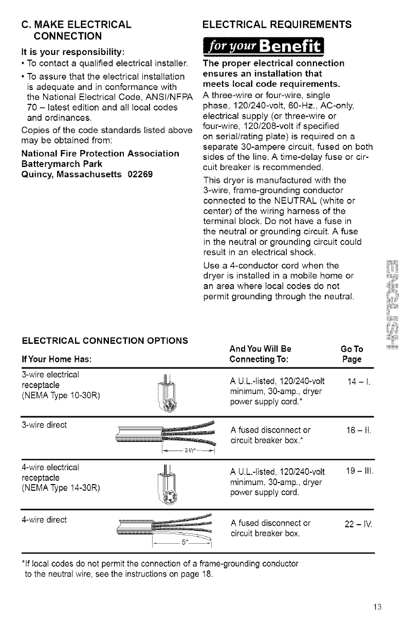
ELECTRICAL CONNECTION OPTIONS
IfYour Home Has:
3-wire electrical
receptacle
(NEMA Type !0-30R)
And YouWill Be GoTo
Connecting To: Page
A U.L.-listed, 120/240-volt
minimum, 30-amp., dryer
power supply cord.*
3-wire direct
4-wire electrical
receptacle
(NEMA Type !4-30R)
14-1.
A fused disconnect or 16 - II.
circuit breaker box.*
A U.L.-listed, 120/240-volt
minimum, 30-amp., dryer
power supply cord.
19 - III.
4-wire direct A fused disconnect or 22 - IV.
circuit breaker box.
*If local codes do not permit the connection of a frame-grounding conductor
to the neutral wire, see the instructions on page 18.
13
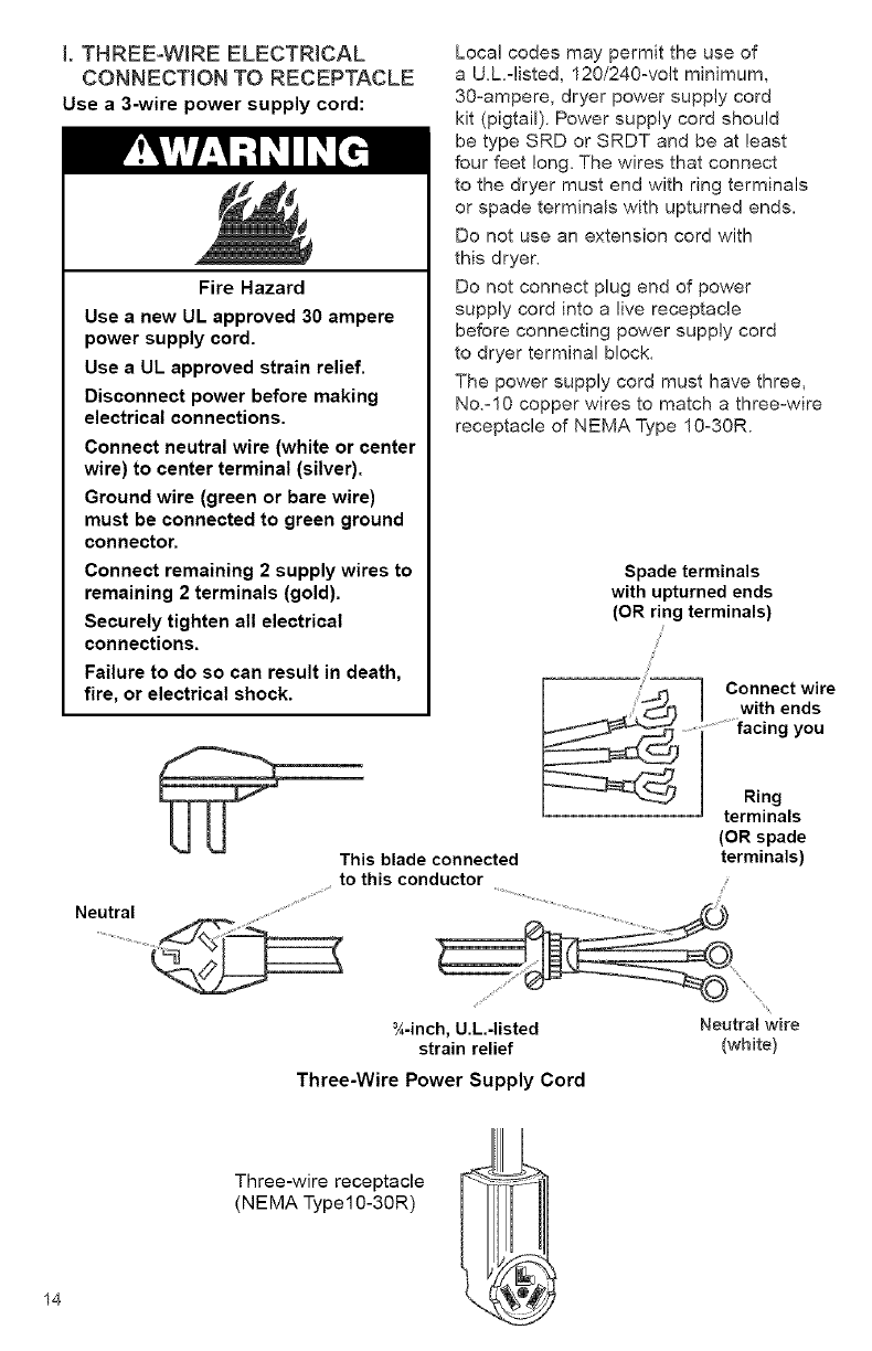
I. THREE-WIRE ELECTRICAL
CONNECTION TO RECEPTACLE
Use a 3-wire power supply cord:
Fire Hazard
Use anew UL approved 30 ampere
power supply cord.
Use aUL approved strain relief.
Disconnect power before making
electrical connections.
Connect neutral wire (white or center
wire) to center terminal (silver).
Ground wire (green or bare wire)
must be connected to green ground
connector.
Connect remaining 2 supply wires to
remaining 2 terminals (gold).
Securely tighten all electrical
connections.
Failure to do so can result in death,
fire, or electrical shock.
Neutral
Local codes may permit the use of
a U.L=listed, 120/240=volt minimum,
30=ampere, dryer power supply cord
kit (pigtail). Power supply cord should
be type SRD or SRDT and be at least
four feet long. The wires that connect
to the dryer must end with ring terminals
or spade terminals with upturned ends.
Do not use an extension cord with
this dryer.
Do not connect plug end of power
supply cord into a live receptacle
before connecting power supply cord
to dryer terminal block.
The power supply cord must have three,
No.-1O copper wires to match a three-wire
receptacle of NEMA Type 10-30R.
Spade terminals
with upturned ends
(OR ring terminals)
lConnect wire
I _._ ,_ I .....with ends
.................facing you
I-- -_-_'_J IRing
'terminals
(OR spade
This blade connected terminals)
to this conductor
¾-inch, U.L.-listed Neutra_ wire
strain relief (white)
Three-Wire Power Supply Cord
14
Three-wire receptacle
(NEMA Typel0-30R)
GROUNDING INSTRUCTIONS
This appliance must be grounded.
In the event of malfunction or
breakdown, grounding will reduce the
risk of electric shock by providing a
path of least resistance for electric
current. The power supply cord must be
plugged into an appropriate outlet that
is properly installed and grounded in
accordance with all local codes and
ordinances.
WARNING: Improper connection
of the equipment-grounding conductor
can result in a risk of electric shock.
Check with aqualified electrician or
serviceman if your are in doubt as to
whether the appliance is properly
grounded.
Do not modify the plug on the power
supply cord. If it will not fit the outlet,
have a proper outlet installed by a
qualified electrician.
SAVE THESE INSTRUCTIONS
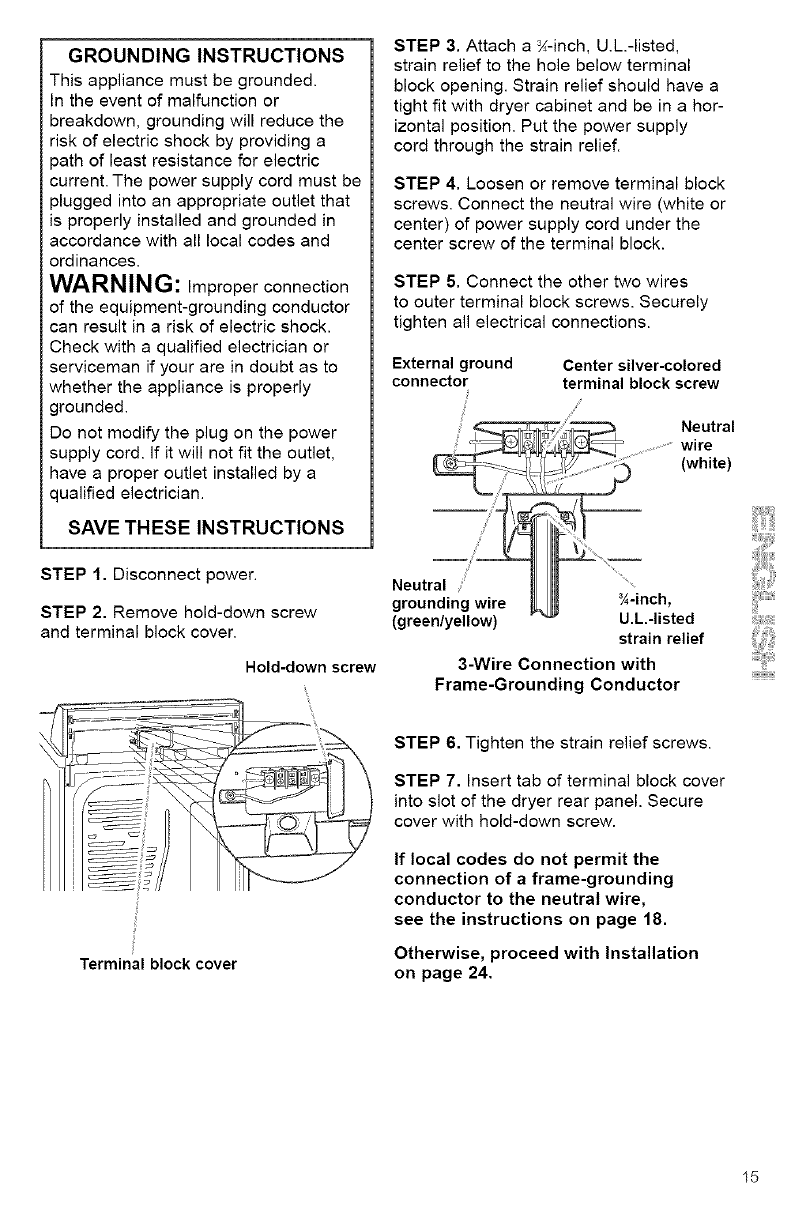
STEP 1. Disconnect power.
STEP 2. Remove hold-down screw
and terminal block cover.
Hold-down screw
STEP 3. Attach a _-inch, U.L.-listed,
strain relief to the hole below terminal
block opening. Strain relief should have a
tight fit with dryer cabinet and be in a hor-
izontal position. Put the power supply
cord through the strain relief.
STEP 4. Loosen or remove terminal block
screws. Connect the neutral wire (white or
center) of power supply cord under the
center screw of the terminal block.
STEP 5. Connect the other two wires
to outer terminal block screws. Securely
tighten all electrical connections.
External ground Center silver-colored
connector terminal block screw
Neutral
wire
(white)
(green/yellow) U.L.-listed
strain relief
3-Wire Connection with
Frame-Grounding Conductor
2
Terminal block cover
STEP 6. Tighten the strain relief screws.
STEP 7. Insert tab of terminal block cover
into slot of the dryer rear panel. Secure
cover with hold-down screw.
If local codes do not permit the
connection of a frame-grounding
conductor to the neutral wire,
see the instructions on page 18.
Otherwise, proceed with Installation
on page 24.
15
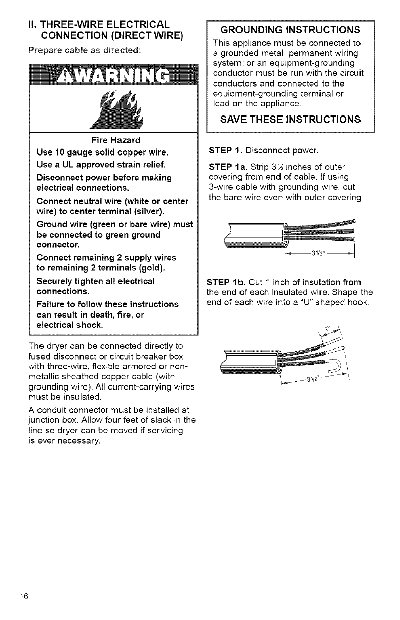
I1. THREE-WIRE ELECTRICAL
CONNECTION (DIRECT WIRE)
Prepare cable as directed:
Fire Hazard
Use 10 gauge solid copper wire.
Use aUL approved strain relief.
Disconnect power before making
electrical connections.
Connect neutral wire (white or center
wire) to center terminal (silver).
Ground wire (green or bare wire) must
be connected to green ground
connector.
Connect remaining 2 supply wires
to remaining 2 terminals (gold).
Securely tighten all electrical
connections.
Failure to follow these instructions
can result in death, fire, or
electrical shock.
The dryer can be connected directly to
fused disconnect or circuit breaker box
with three-wire, flexible armored or non-
metallic sheathed copper cable (with
grounding wire). All current-carrying wires
must be insulated.
A conduit connector must be installed at
junction box. Allow four feet of slack in the
line so dryer can be moved if servicing
is ever necessary.
GROUNDING INSTRUCTIONS
This appliance must be connected to
a grounded metal, permanent wiring
system; or an equipment-grounding
conductor must be run with the circuit
conductors and connected to the
equipment-grounding terminal or
lead on the appliance.
SAVE THESE INSTRUCTIONS
STEP 1. Disconnect power.
STEP la. Strip 3_ inches of outer
covering from end of cable. If using
3-wire cable with grounding wire, cut
the bare wire even with outer covering.
STEP lb. Cut 1 inch of insulation from
the end of each insulated wire. Shape the
end of each wire into a "U" shaped hook.
16
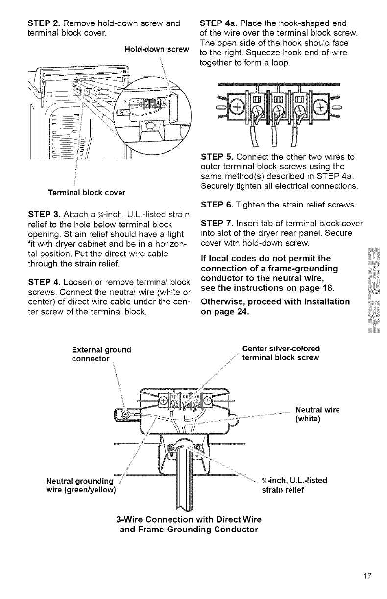
STEP2.Removehold-downscrewand
terminalblockcover.
Hold-downscrew
Terminal block cover
STEP 3. Attach a N-inch, U.L.-listed strain
relief to the hole below terminal block
opening. Strain relief should have a tight
fit with dryer cabinet and be in a horizon-
tal position. Put the direct wire cable
through the strain relief.
STEP 4. Loosen or remove terminal block
screws. Connect the neutral wire (white or
center) of direct wire cable under the cen-
ter screw of the terminal block.
External ground
connector
/
J
Y
S
Neutral grounding
wire (green/yellow)
STEP 4a. Place the hook-shaped end
of the wire over the terminal block screw.
The open side of the hook should face
to the right. Squeeze hook end of wire
together to form a loop.
STEP 5. Connect the other two wires to
outer terminal block screws using the
same method(s) described in STEP 4a.
Securely tighten all electrical connections.
STEP 6. Tighten the strain relief screws.
STEP 7. insert tab of terminal block cover
into slot of the dryer rear panel. Secure
cover with hold-down screw.
If local codes do not permit the
connection of a frame-grounding
conductor to the neutral wire,
see the instructions on page 18.
Otherwise, proceed with Installation
on page 24.
Center silver-colored
terminal block screw
S
S
Neutral wire
(white)
.....N-inch, U.L.-listed
strain relief
3-Wire Connection with Direct Wire
and Frame-Grounding Conductor
17
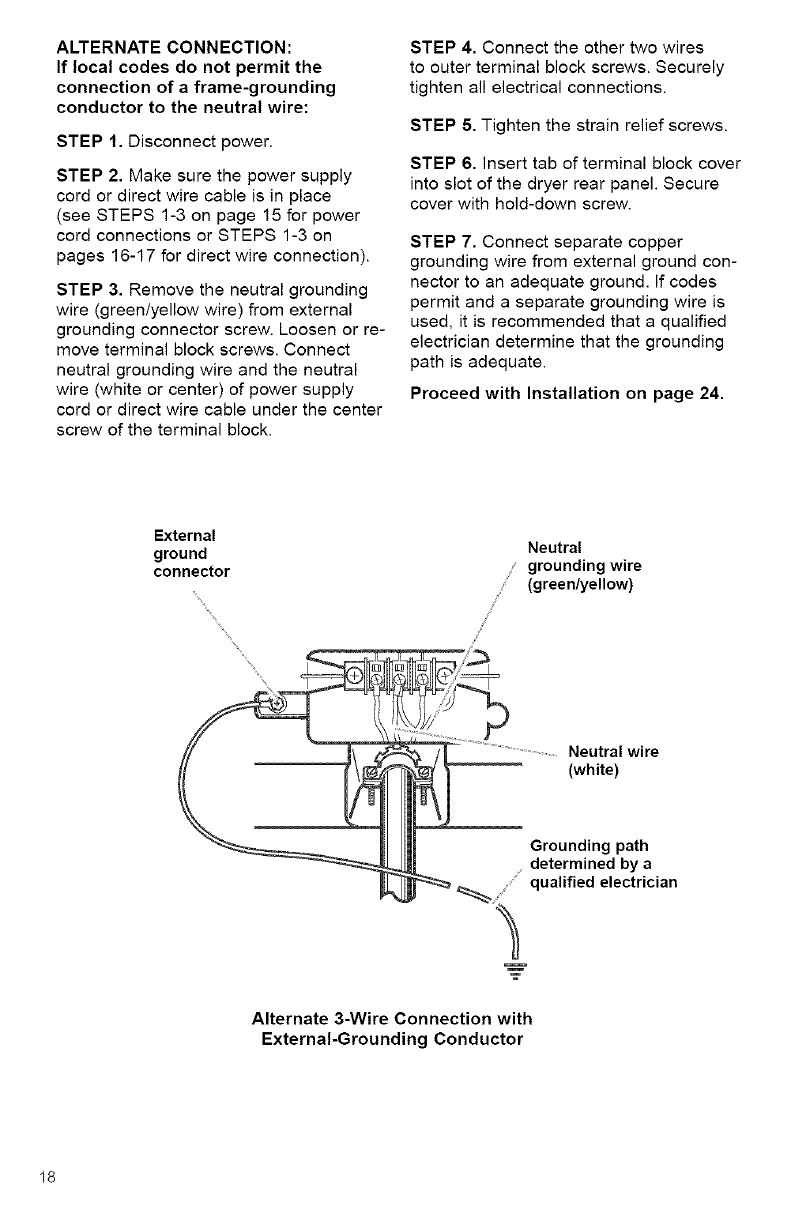
ALTERNATE CONNECTION:
If local codes do not permit the
connection of a frame-grounding
conductor to the neutral wire:
STEP 1. Disconnect power.
STEP 2. Make sure the power supply
cord or direct wire cable is in place
(see STEPS 1-3 on page 15 for power
cord connections or STEPS 1-3 on
pages 16-17 for direct wire connection).
STEP 3. Remove the neutral grounding
wire (green/yellow wire) from external
grounding connector screw. Loosen or re-
move terminal block screws. Connect
neutral grounding wire and the neutral
wire (white or center) of power supply
cord or direct wire cable under the center
screw of the terminal block.
STEP 4. Connect the other two wires
to outer terminal block screws. Securely
tighten all electrical connections.
STEP 5. Tighten the strain relief screws.
STEP 6. Insert tab of terminal block cover
into slot of the dryer rear panel. Secure
cover with hold-down screw.
STEP 7. Connect separate copper
grounding wire from external ground con-
nector to an adequate ground. If codes
permit and a separate grounding wire is
used, it is recommended that a qualified
electrician determine that the grounding
path is adequate.
Proceed with Installation on page 24.
External
ground
connector
Neutral
grounding wire
(green/yellow)
/
J
J
Neutral wire
(white)
Grounding path
determined by a
qualified electrician
Alternate 3-Wire Connection with
External-Grounding Conductor
18
II1.MAKE FOUR-WIRE
ELECTRICAL CONNECTION
TO RECEPTACLE
Use a 4-wire power supply cord:
Fire Hazard
Use anew UL approved 30 ampere
power supply cord.
Use aUL approved strain relief.
Disconnect power before making
electrical connections.
Connect neutral wire (white or center
wire) to center terminal (silver).
Ground wire (green or bare wire)
must be connected to green ground
connector.
Connect remaining 2 supply wires to
remaining 2 terminals (gold).
Securely tighten all electrical
connections.
Failure to do so can result in death,
fire, or electrical shock.
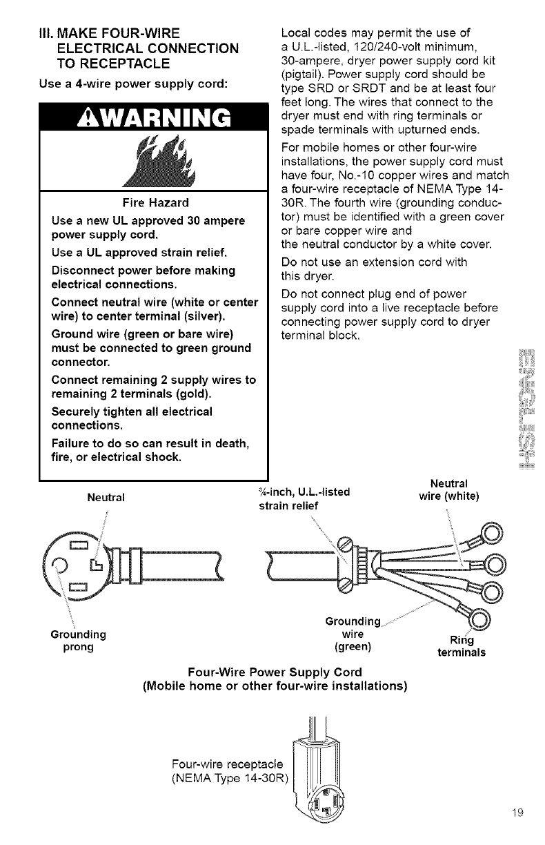
Neutral
Local codes may permit the use of
a U.L.-listed, 120/240-volt minimum,
3g-ampere, dryer power supply cord kit
(pigtail). Power supply cord should be
type SRD or SRDT and be at least four
feet long. The wires that connect to the
dryer must end with ring terminals or
spade terminals with upturned ends.
For mobile homes or other four-wire
installations, the power supply cord must
have four, No.-10 copper wires and match
a four-wire receptacle of NEMA Type 14-
30R. The fourth wire (grounding conduc-
tor) must be identified with a green cover
or bare copper wire and
the neutral conductor by a white cover.
Do not use an extension cord with
this dryer.
Do not connect plug end of power
supply cord into a live receptacle before
connecting power supply cord to dryer
terminal block.
_-inch, U.L.-listed
strain relief
Neutral
wire (white)
Grounding
prong
Groundinc
wire
(green)
Four-Wire Power Supply Cord
(Mobile home or other four-wire installations)
Four-wire receptacle
(NEMA Type 14-30R) 1
Ring
terminals
19
GROUNDING INSTRUCTIONS
This appliance must be grounded. In
the event of malfunction or breakdown,
grounding will reduce the risk of electric
shock by providing a path of least
resistance for electric current. The
power supply cord must be plugged
into an appropriate outlet that is
properly installed and grounded in
accordance with all local codes and
ordinances.
WARN ING: Improper connection
of the equipment-grounding conductor
can result in a risk of electric shock.
Check with a qualified electrician or
serviceman if your are in doubt as to
whether the appliance is properly
grounded.
Do not modify the plug on the power
supply cord. If it will not fit the outlet,
have a proper outlet installed by a
qualified electrician.
SAVE THESE INSTRUCTIONS
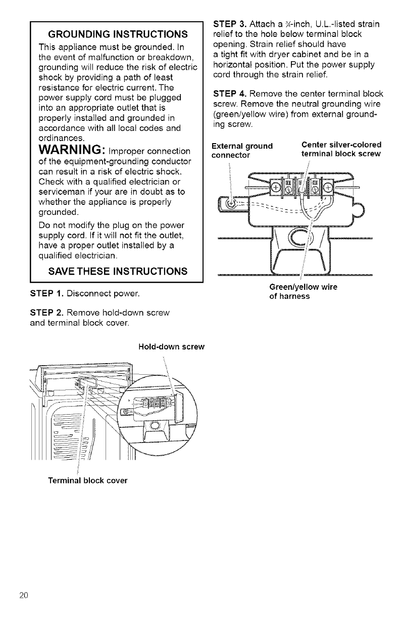
STEP 1. Disconnect power.
STEP 2, Remove hold-down screw
and terminal block cover.
Hold-down screw
STEP 3. Attach a g-inch, U.L.-listed strain
relief to the hole below terminal block
opening. Strain relief should have
a tight fit with dryer cabinet and be in a
horizontal position. Put the power supply
cord through the strain relief.
STEP 4. Remove the center terminal block
screw. Remove the neutral grounding wire
(green/yellow wire) from external ground-
ing screw.
External ground Center silver-colored
connector terminal block screw
Green/yellow wire
of harness
Terminal block cover
2O
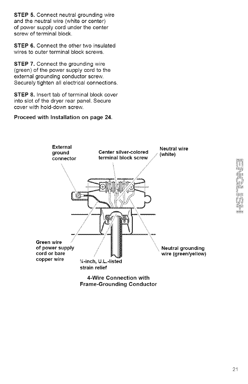
STEP5.Connectneutralgroundingwire
andtheneutralwire(whiteorcenter)
ofpowersupplycordunderthecenter
screwofterminalblock.
STEP6.Connecttheothertwoinsulated
wirestoouterterminalblockscrews.
STEP7.Connectthegroundingwire
(green)ofthepowersupplycordtothe
external grounding conductor screw.
Securely tighten all electrical connections.
STEP 8. insert tab of terminal block cover
into slot of the dryer rear panel. Secure
cover with hold-down screw.
Proceed with Installation on page 24.
External
ground
connector
\
\\\\
Neutral wire
Center silver-colored (white)
terminal block screw /
/
S
,S /
Green wire
of power supply
cord or bare
copper wire _/,-inch, U.L.-listed
strain relief
\
_ Neutral grounding
wire (green/yellow)
4-Wire Connection with
Frame-Grounding Conductor
21
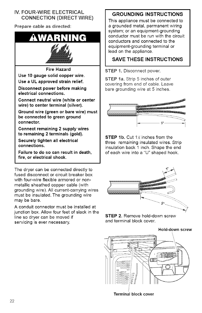
iV. FOUR-WIRE ELECTRICAL
CONNECTION (DIRECT WIRE)
Prepare cable as directed:
Fire Hazard
Use 10 gauge solid copper wire.
Use a UL approved strain relief.
Disconnect power before making
electrical connections.
Connect neutral wire (white or center
wire) to center terminal (silver).
Ground wire (green or bare wire) must
be connected to green ground
connector.
Connect remaining 2 supply wires
to remaining 2 terminals (gold).
Securely tighten all electrical
connections.
Failure to do so can result in death,
fire, or electrical shock.
The dryer can be connected directly to
fused disconnect or circuit breaker box
with four-wire flexible armored or non-
metallic sheathed copper cable (with
grounding wire). All current-carrying wires
must be insulated. The grounding wire
may be bare.
A conduit connector must be installed at
junction box. Allow four feet of slack in the
line so dryer can be moved if
servicing is ever necessary.
GROUNDING INSTRUCTIONS
This appliance must be connected to
a grounded metal, permanent wiring
system; or an equipment-grounding
conductor must be run with the circuit
conductors and connected to the
equipment-grounding terminal or
lead on the appliance.
SAVE THESE INSTRUCTIONS
STEP 1. Disconnect power.
STEP la. Strip 5 inches of outer
covering from end of cable. Leave
bare grounding wire at 5 inches.
STEP lb. Cut 1_ inches from the
three remaining insulated wires. Strip
insulation back 1 inch. Shape the end
of each wire into a "U" shaped hook.
STEP 2, Remove hold-down screw
and terminal block cover.
Hold-down screw
22
Terminal block cover
STEP 3. Attach a K-inch, U.L.-listed strain
relief to the hole below terminal block
opening. Strain relief should have a tight
fit with dryer cabinet and be in a horizon-
tal position. Put the direct wire cable
through the strain relief.
STEP 6. Place the hook-shaped end of
the wire over the terminal block screw.
The open side of the hook should face
to the right. Squeeze hook end of wire to-
gether to form a loop.
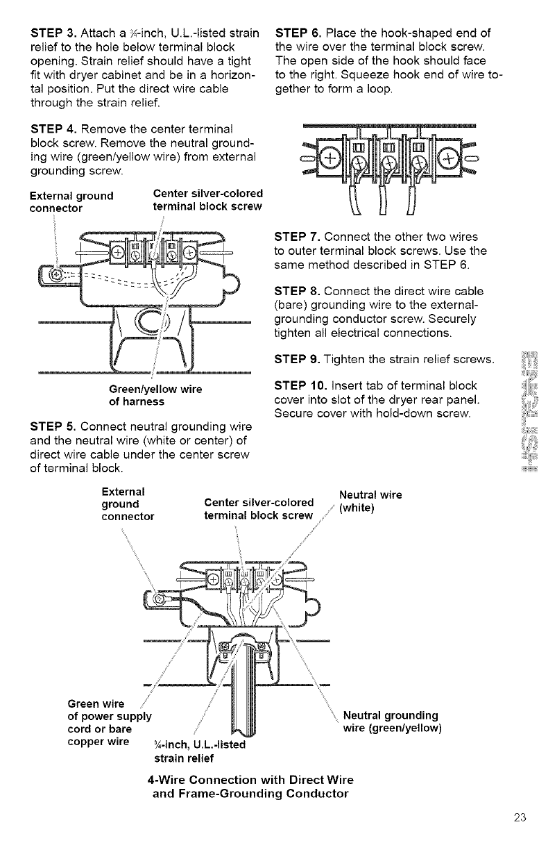
STEP 4. Remove the center terminal
block screw. Remove the neutral ground-
ing wire (green/yellow wire) from external
grounding screw.
External ground Center silver-colored
connector terminal block screw
STEP 7. Connect the other two wires
to outer terminal block screws. Use the
same method described in STEP 6.
STEP 8. Connect the direct wire cable
(bare) grounding wire to the external-
grounding conductor screw. Securely
tighten all electrical connections.
STEP 9. Tighten the strain relief screws.
Green/yellow wire
of harness
STEP 5. Connect neutral grounding wire
and the neutral wire (white or center) of
direct wire cable under the center screw
of terminal block.
STEP 10. insert tab of terminal block
cover into slot of the dryer rear panel.
Secure cover with hold-down screw.
External
ground
connector
Neutral wire
Center silver-colored ........(white)
terminal block screw
!i
j_
/
j J
Green wire /
of power supply
cord or bare
copper wire N-inch, U.L.-listed
strain relief
Neutral grounding
wire (green/yellow)
4-Wire Connection with Direct Wire
and Frame-Grounding Conductor
23
D. CONNECT EXHAUST
_"te,Jii,_toJ,_m"-[_ a[:..)1["
A properly exhausted dryer will give
you the shortest drying time, lower
your utility bills, and extend the life
of the dryer.
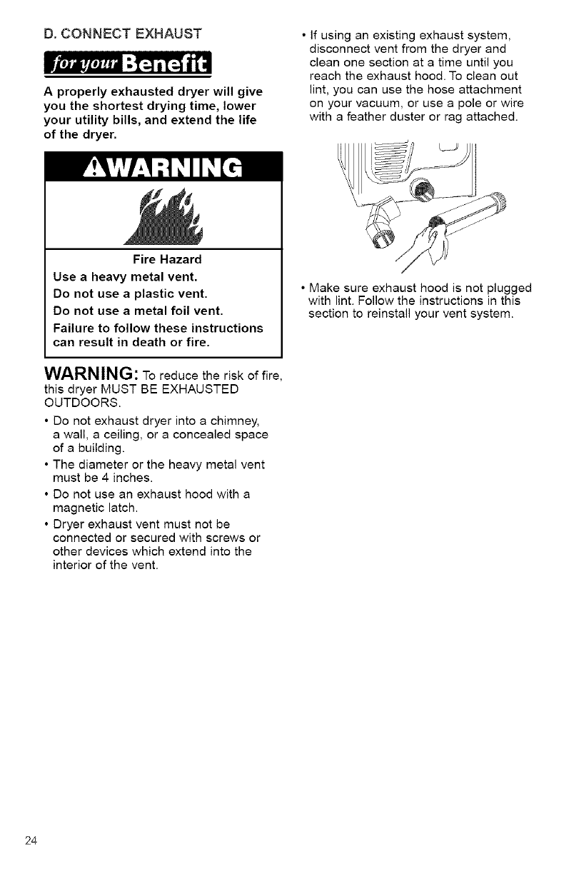
• If using an existing exhaust system,
disconnect vent from the dryer and
clean one section at a time until you
reach the exhaust hood. To clean out
lint, you can use the hose attachment
on your vacuum, or use a pole or wire
with a feather duster or rag attached.
Fire Hazard
Use aheavy metal vent.
Do not use aplastic vent.
Do not use a metal foil vent.
Failure to follow these instructions
can result in death or fire.
WARNING: To reduce the risk of fire,
this dryer MUST BE EXHAUSTED
OUTDOORS.
•Do not exhaust dryer into a chimney,
a wail, a ceiling, or a concealed space
of a building.
• The diameter or the heavy metal vent
must be 4 inches.
• Do not use an exhaust hood with a
magnetic latch.
• Dryer exhaust vent must not be
connected or secured with screws or
other devices which extend into the
interior of the vent.
• Make sure exhaust hood is not plugged
with lint. Follow the instructions in this
section to reinstall your vent system.
24
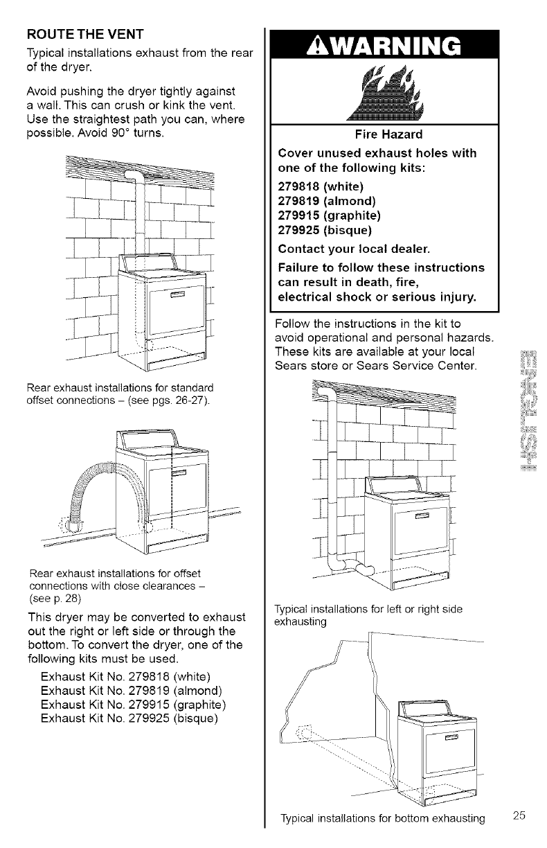
ROUTE THE VENT
Typical installations exhaust from the rear
of the dryer.
Avoid pushing the dryer tightly against
a wall. This can crush or kink the vent.
Use the straightest path you can, where
possible. Avoid 90 ° turns.
Rear exhaust installations for standard
offset connections - (see pgs. 26-27).
Rear exhaust installations for offset
connections with close clearances -
(see p. 28)
This dryer may be converted to exhaust
out the right or left side or through the
bottom. To convert the dryer, one of the
following kits must be used.
Exhaust Kit No. 279818 (white)
Exhaust Kit No. 279819 (almond)
Exhaust Kit No. 279915 (graphite)
Exhaust Kit No. 279925 (bisque)
Fire Hazard
Cover unused exhaust holes with
one of the following kits:
279818 (white)
279819 (almond)
279915 (graphite)
279925 (bisque)
Contact your local dealer.
Failure to follow these instructions
can result in death, fire,
electrical shock or serious injury.
Follow the instructions in the kit to
avoid operational and personal hazards.
These kits are available at your local
Sears store or Sears Service Center.
Typical installations for left or right side
exhausting
Typical installations for bottom exhausting 25
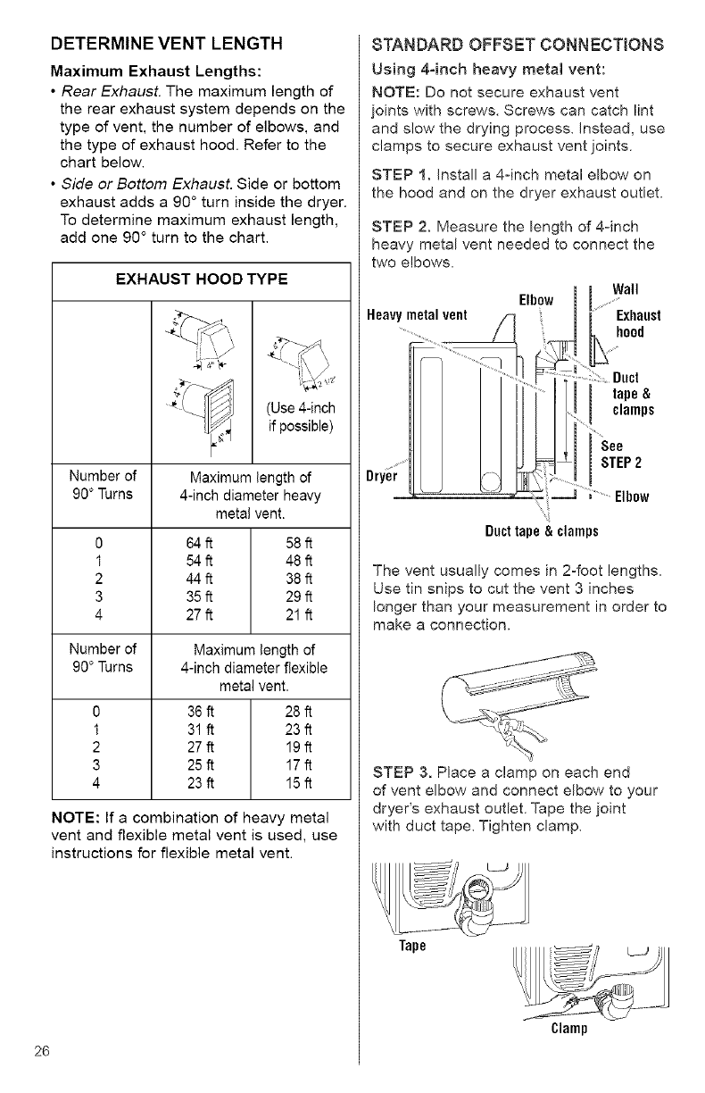
DETERMINEVENTLENGTH
MaximumExhaustLengths:
•Rear Exhaust. The maximum length of
the rear exhaust system depends on the
type of vent, the number of elbows, and
the type of exhaust hood. Refer to the
chart below.
• Side or Bottom Exhaust. Side or bottom
exhaust adds a 90 ° turn inside the dryer.
To determine maximum exhaust length,
add one 90 ° turn to the chart.
EXHAUST HOOD TYPE
Number of
90 ° Turns
0
1
2
3
4
Number of
90 ° Turns
0
1
2
3
4
(Use 4-inch
if possible)
Maximum length of
4-inch diameter heavy
metal vent.
64 ft 58 ft
54 ft 48 ft
44 ft 38 ft
35 ft 29 ft
27 ft 21 ft
Maximum length of
4-inch diameter flexible
metal vent.
36 ft 28 ft
31 ft 23 ft
27ft 19 ft
25ft 17 ft
23ff 15 ft
NOTE: If a combination of heavy metal
vent and flexible metal vent is used, use
instructions for flexible metal vent.
26
STANDARD OFFSET CONNECTION8
Using 4°inch heavy metal vent:
NOTE: Do not secure exhaust vent
joints with screws. Screws can catch lint
and slow the drying process. Instead, use
clamps to secure exhaust vent joints.
STEP 1. Install a 4-inch metal elbow on
the hood and on the dryer exhaust outlet.
STEP 2. Measure the length of 4-inch
heavy metal vent needed to connect the
two elbows.
Heavy metal vent /_
Elbow
]
iWall
[Exhaust
hoo,
.....:?::: Duct
tape &
.....I clamps
See
ISTEP2
....... Elbow
Ducttape& clamps
The vent usually comes in 2=foot lengths.
Use tin snips to cut the vent 3 inches
longer than your measurement in order to
make a connection.
STEP 3. Place a clamp on each end
of vent elbow and connect elbow to your
dryer's exhaust outlet. Tape the joint
with duct tape. Tighten clamp.
Tape
Clamp
STEP4.Connectventtoelbow.Tapethe
jointwithducttape.Tightenclamp.
STEP 5. Install one end of elbow on vent,
the other end to the exhaust hood. Tape
joints and tighten clamps.
Finish Installation. See "REVIEW
INSTALLATION".
STEP 5. Place a clamp on each end of
vent elbow. Install one end of elbow on
vent, the other end to the exhaust hood.
Tape joints and tighten clamps.
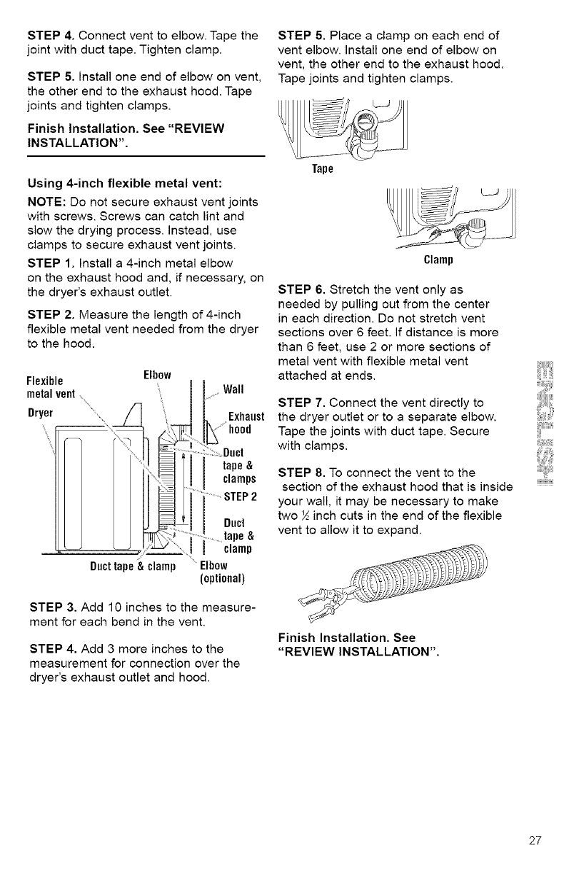
Using 4-inch flexible metal vent:
NOTE: Do not secure exhaust vent joints
with screws. Screws can catch lint and
slow the drying process, instead, use
clamps to secure exhaust vent joints.
STEP 1. Install a 4-inch metal elbow
on the exhaust hood and, if necessary, on
the dryer's exhaust outlet.
STEP 2. Measure the length of 4-inch
flexible metal vent needed from the dryer
to the hood.
Elbow
Flexible
metalvent_
Dryer
Ducttape &clamp
Wall
Exhaust
hood
:Duct
tape&
clamps
...............STEP2
Duct
.... tape&
clamp
....Elbow
(optional)
STEP 3. Add 10 inches to the measure-
ment for each bend in the vent.
STEP 4. Add 3 more inches to the
measurement for connection over the
dryer's exhaust outlet and hood.
Tape
Clamp
STEP 6. Stretch the vent only as
needed by pulling out from the center
in each direction. Do not stretch vent
sections over 6 feet. If distance is more
than 6 feet, use 2 or more sections of
metal vent with flexible metal vent
attached at ends.
STEP 7. Connect the vent directly to
the dryer outlet or to a separate elbow.
Tape the joints with duct tape. Secure
with clamps.
STEP 8. To connect the vent to the
section of the exhaust hood that is inside
your wall, it may be necessary to make
two ½ inch cuts in the end of the flexible
vent to allow it to expand.
Finish Installation. See
"REVIEW INSTALLATION".
27
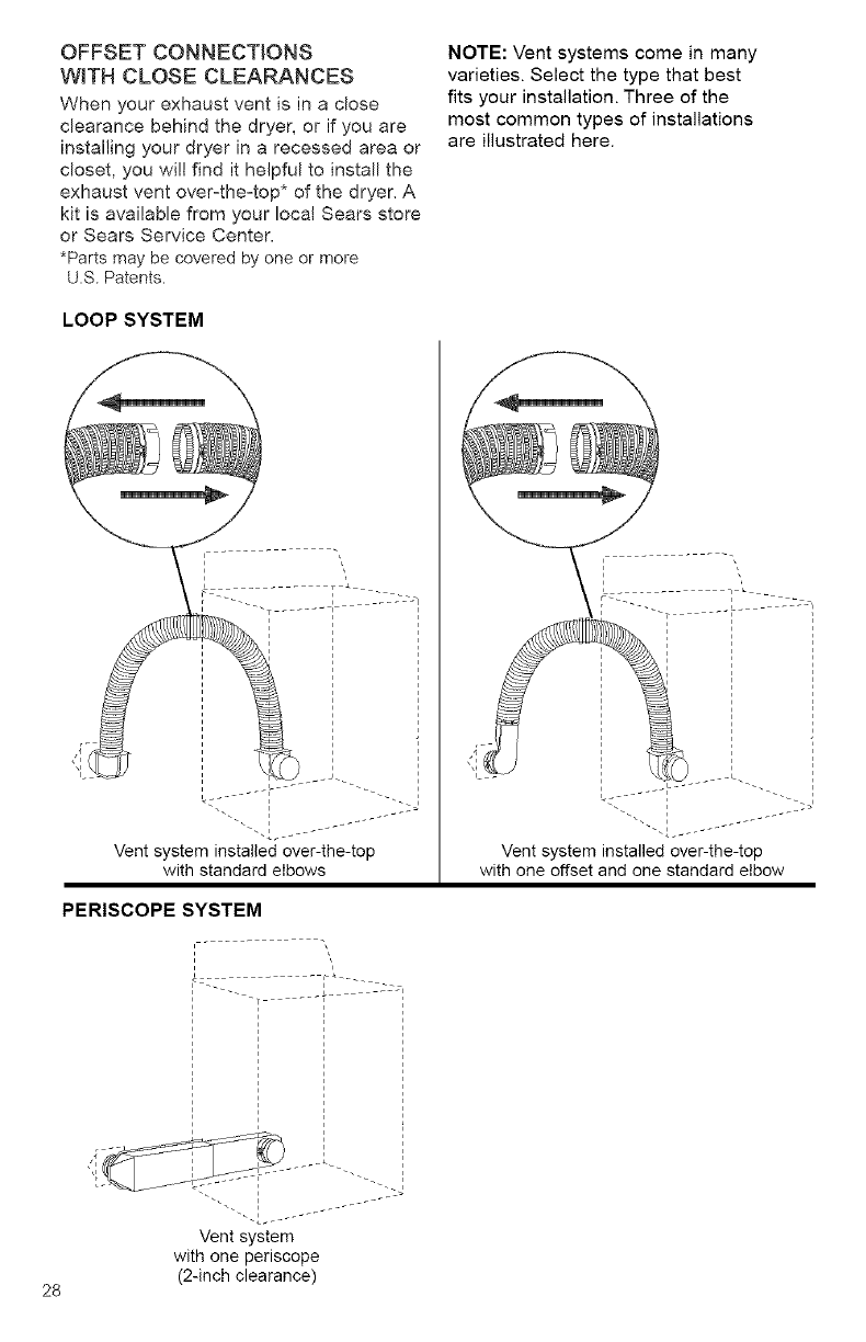
OFFSET CONNECTIONS
WITH CLOSE CLEARANCES
When your exhaust vent is in a dose
clearance behind the dryer, or if you are
installing your dryer in a recessed area or
closet, you wi!l find it helpful to install the
exhaust vent over-the-top* of the dryer. A
kit is available from your local Sears store
or Sears Service Center.
*Parts may be covered by one or more
U.S. Patents.
LOOP SYSTEM
NOTE: Vent systems come in many
varieties. Select the type that best
fits your installation. Three of the
most common types of installations
are illustrated here.
I _ L ...... - J'"
Vent system installed over-the-top
with standard elbows
PERISCOPE SYSTEM
I
I
I
I
28
. ____-
Vent system
with one periscope
(2-inch clearance)
REVIEW INSTALLATION
i l'Ji_l'jlli :1_] i[_-] _|
Take afew minutes to complete
this checklist. It will help assure you
that you have a proper installation
and increase your satisfaction with
your Kenmore ELITE TM dryer.
[] Check that all parts you removed
from the parts packages are now
installed.
[] Ensure that dryer is positioned in its fi-
nal location. Make sure vent is not
crushed or kinked.
[] Ensure that dryer is level by placing
a level on top of the dryer. Check side-
to-side first, then check front-to-back. If
dryer is not level, adjust the legs up or
down.
[] Check to make sure you have all
the tools you started with.
FINAL STEPS
[] Plug the power supply cord into the
grounded outlet or connect direct
wire to power supply.
[] Turn power supply on.
[] Wipe the interior of the drum
thoroughly with a damp cloth to
remove any dust.
[] Remove the blue protective film on
the console and any tape remaining on
dryer.
[] Start the dryer and allow it to
complete a full heat cycle (not the
AIR DRY Cycle). After five minutes,
open dryer door. You should feel
heat inside the dryer. If you do not
feel heat, see "TROUBLESHOOTING".
NOTE: You may notice a burning odor.
This smell is common when the
heating element is first used. The smell
will go away.
[] Read the rest of this manual to fully
understand your new dryer.
iYiiiiiiii_iii@i
29
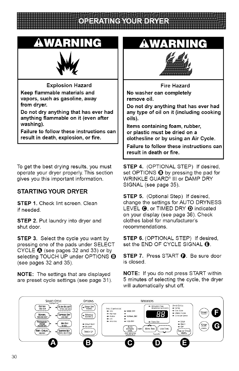
Explosion Hazard
Keep flammable materials and
vapors, such as gasoline, away
from dryer.
Do not dry anything that has ever had
anything flammable on it (even after
washing).
Failure to follow these instructions can
result in death, explosion, or fire.
Fire Hazard
No washer can completely
remove oil.
Do not dry anything that has ever had
any type of oil on it (including cooking
oils).
Items containing foam, rubber,
or plastic must be dried on a
clothesline or by using an Air Cycle.
Failure to follow these instructions can
result in death or fire.
To get the best drying results, you must
operate your dryer properly. This section
gives you this important information.
STARTING YOUR DRYER
STEP 1. Check lint screen. Clean
if needed.
STEP 2. Put laundry into dryer and
shut door.
STEP 4. (OPTIONAL STEP) If desired,
set OPTIONS _) by pressing the pad for
WRINKLE GUARD ® Ill or DAMP DRY
SIGNAL (see page 35).
STEP 5. (Optional Step) If desired,
change the settings for AUTO DRYNESS
LEVEL (_, or TIMED DRY _) indicated
on your display (see page 36). Check
clothes label for manufacturer's
recommendations.
STEP 3. Select the cycle you want by
pressing one of the pads under SELECT
CYCLE Q (see pages 32 and 33) or by
selecting TOUCH UP under OPTIONS _)
(see pages 32 and 35).
STEP 6. (OPTIONAL STEP) If desired,
set the END OF CYCLE SIGNAL _.
STEP 7. Press START _). Be sure door
is closed.
NOTE: The settings that are displayed
are preset cycle settings (see page 31).
NOTE: If you do not press START within
5 minutes of selecting the cycle, the dryer
will automatically shut off.
A0-
MODIFIERS /@
J
3O
PAUSING/STOPPING/RESTARTING
YOUR DRYER
• To pause the drying cycle at
any time, open the door or press
STOP/CANCEL O once.
• To restart the dryer, close the door and
press START O.
NOTE: Drying will continue from where
the cycle was interrupted if you close the
door and press START within 5 minutes. If
the cycle is interrupted for more than
5 minutes, the dryer will shut off.You will
need to reset the settings for your cycle
before restarting the dryer.
• If you wish to end your drying cycle,
press STOP/CANCEL O twice.
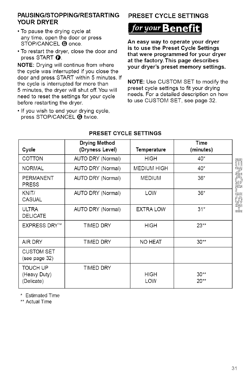
PRESET CYCLE SETTINGS
An easy way to operate your dryer
is to use the Preset Cycle Settings
that were programmed for your dryer
at the factory. This page describes
your dryer's preset memory settings.
NOTE: Use CUSTOM SET to modify the
preset cycle settings to fit your drying
needs. For a detailed description on how
to use CUSTOM SET, see page 32.
PRESET CYCLE SETTINGS
Drying Method Time
Cycle (Dryness Level) Temperature (minutes)
COTTON AUTO DRY (Normal) HIGH 40*
NORMAL AUTO DRY (Normal) MEDIUM HIGH 40*
PERMANENT AUTO DRY (Normal) MEDIUM 36*
PRESS
KNIT/ AUTO DRY (Normal) LOW 36*
CASUAL
ULTRA AUTO DRY (Normal) EXTRA LOW 31"
DELICATE
EXPRESS DRY TM TIMED DRY HIGH 23**
AIR DRY TIMED DRY NO HEAT 30**
CUSTOM SET
(see page 32)
TOUCH UP TIMED DRY
(Heavy Duty) HIGH 30**
(Delicate) LOW 20**
* Estimated Time
** Actual Time
31
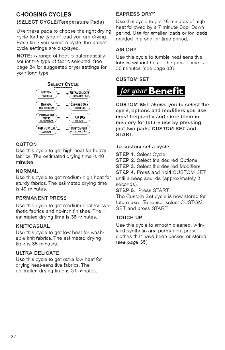
CHOOSINGCYCLES
(SELECTCYCLE/TemperaturePads)
Usethesepadstochoosetherightdrying
cycleforthetypeofloadyouare drying.
Each time you select a cycle, the preset
cycle settings are displayed.
NOTE: A range of heat is automatically
set for the type of fabric selected. See
page 34 for suggested dryer settings for
your load type.
SELECT CYCLE
TEMPERATURE
_MED'F_IGH HEA_ _HIGH HEAT _
-@
C OTTO N
Use this cycle to get high heat for heavy
fabrics. The estimated drying time is 40
minutes.
NORMAL
Use this cycle to get medium high heat for
sturdy fabrics. The estimated drying time
is 40 minutes.
PERMANENT PRESS
Use this cycle to get medium heat for syn-
thetic fabrics and no-iron finishes, The
estimated drying time is 36 minutes.
KN_T/CASUAL
Use this cycle to get low heat for wash°
able knit fabrics. The estimated drying
time is 36 minutes,
ULTRA DELBCATE
Use this cycle to get extra low heat for
drying heat-sensitive fabrics. The
estimated drying time is 31 minutes.
EXPRESS DRY TM
Use this cycle to get 16 minutes of high
heat followed by a 7 minute Cool Down
period. Use for smaller loads or for loads
needed in a shorter time period.
AIR DRY
Use this cycle to tumble heat sensitive
fabrics without heat. The preset time is
30 minutes (see page 33).
CUSTOM SET
iteJ_,,,mJ,_a=;,%Ni[_ 1["
CUSTOM SET allows you to select the
cycle, options and modifiers you use
most frequently and store them in
memory for future use by pressing
just two pads: CUSTOM SET and
START.
To custom set a cycle:
STEP 1. Select Cycle.
STEP 2. Select the desired Options.
STEP 3. Select the desired Modifiers.
STEP 4. Press and hold CUSTOM SET
until a beep sounds (approximately 3
seconds).
STEP 5. Press START.
The Custom Set cycle is now stored for
future use. To reuse, select CUSTOM
SET and press START.
TOUCN UP
Use this cycle to smooth cleaned, wrin-
kled synthetic and permanent press
clothes that have been packed or stored
(see page 35).
32
USING AIR DRY
.il'Ji_l'Jlli _,][t.] i['_J _[i_
Using this cycle gives you all the
benefits of hang drying with a shorter
drying time.
Use the AiR DRY Cycle for items that will
not tolerate heat such as plastics and
foam rubber. Also use for airing and
fluffing items such as pillows.
•The AIR DRY Cycle is preset for
30 minutes but can be adjusted from
1 to 99 minutes any time during the
cycle.
• An AUTO DRYNESS LEVEL selection
cannot be made when using the AIR
DRY Cycle. Pressing this pad will result
in three short tones sounding - which
indicates an unavailable option was
selected.
SELECT CYCLE
TEMPERATURE
C0TT0. . LTR,O,L,CAT
HIGH HEAT
NORMAL _m w_ExPRESS DRY_
MED-HIGH HEATj)
PERMANEXT_ _
PRESS / _* o AIRDRY
MEDIUM HEAT jNO HEAT
UK""'CASUA °°SC0s'0MSE'
Refer to the following table for examples
of items that require drying without heat.
Use the AIR DRY Cycle, or place the
items on a line or rack to air dry.
Type of Load
RUBBER, PLASTIC, HEAT-SENSITIVE FABRICS
Foam rubber - Pillows, padded bras, stuffed toys
•Make sure coverings are securely stitched.
• Shake and fluff pillows by hand several times during the cycle.
• Make sure pillows are completely dry. Foam rubber pillows
take a long time to dry.
Plastic - Shower curtains, tablecloths
Rubber-backed rugs
Olefin, polypropylene, sheer nylon
TIME (minutes)*
20-30 min.
20-30 min.
40-50 min.
10-20 min.
*Reset time as needed to complete drying.
33
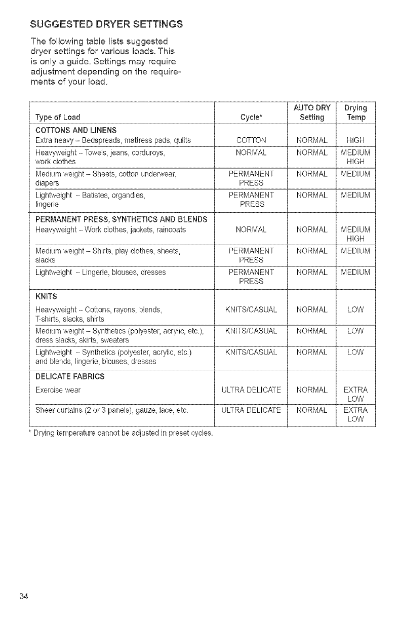
SUGGESTED DRYER SETTINGS
The following table lists suggested
dryer settings for various loads. This
is only a guide. Settings may require
adjustment depending on the require=
merits of your load.
AUTO DRY Drying
Type of Load Cycle* Setting Temp
COTTONS AND LINENS
Extra heavy - Bedspreads, mattress pads, quilts COTTON NORMAL HIGH
Heavyweight - Towels, jeans, corduroys, NORMAL NORMAL MEDIUM
work clothes HIGH
Medium weight - Sheets, cotton underwear, PERMANENT NORMAL MEDIUM
diapers PRESS
Lightweight - Batistes, organdies, PERMANENT NORMAL MEDIUM
lingerie PRESS
PERMANENT PRESS, SYNTHETICS AND BLENDS
Heavyweight - Work clothes, jackets, raincoats NORMAL NORMAL MEDIUM
HIGH
Medium weight - Shirts, play clothes, sheets, PERMANENT NORMAL MEDIUM
slacks PRESS
Lightweight - Lingerie, blouses, dresses PERMANENT NORMAL MEDIUM
PRESS
KNITS
Heavyweight - Cottons, rayons_blends_ KNITS/CASUAL NORMAL LOW
T-shirts, slacks, shirts
Medium weight - Synthetics (polyester, acrylic, etc), KNITS/CASUAL NORMAL LOW
dress slacks, skirts, sweaters
Lightweight - Synthetics (polyester, acrylic, etc) KNITS/CASUAL NORMAL LOW
and blends, lingerie, blouses, dresses
DELICATE FABRICS
Exercise wear ULTRADELICATE NORMAL EXTRA
LOW
Sheer curtains (2 or 3 panels), gauze, lace, etc. ULTRA DELICATE NORMAL EXTRA
LOW
* Drying temperature cannot be adjusted in preset cycles.
34
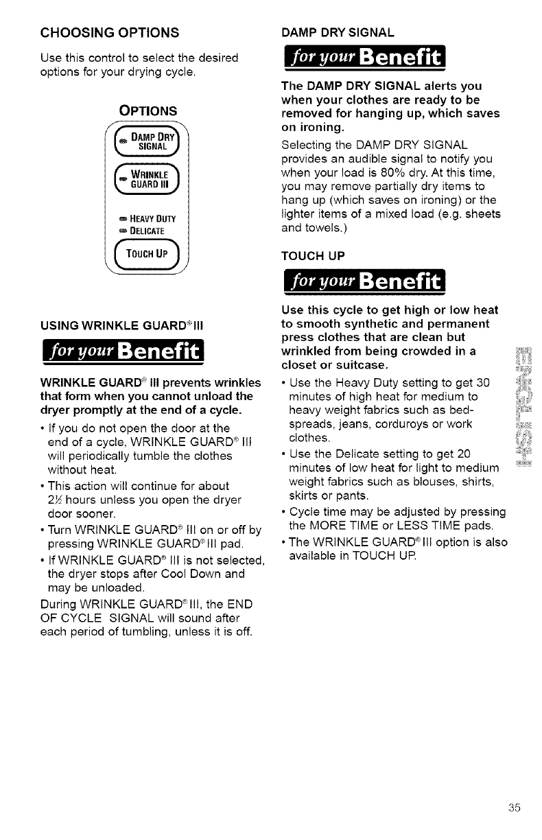
CHOOSING OPTIONS
Use this control to select the desired
options for your drying cycle.
OPTIONS
DAMPDRY
SIGNAL
oHEAVY DUTY
DELICATE
USING WRINKLE GUARD°Ill
WRINKLE GUARD _ III prevents wrinkles
that form when you cannot unload the
dryer promptly at the end of a cycle.
• If you do not open the door at the
end of a cycle, WRINKLE GUARD _ Ill
will periodically tumble the clothes
without heat.
• This action will continue for about
2>:; hours unless you open the dryer
door sooner.
• Turn WRINKLE GUARD <_Ill on or off by
pressing WRINKLE GUARD®Ill pad.
• If WRINKLE GUARD ® III is not selected,
the dryer stops after Cool Down and
may be unloaded.
During WRINKLE GUARD®Ill, the END
OF CYCLE SIGNAL will sound after
each period of tumbling, unless it is off.
DAMP DRY SIGNAL
.il,Ji_tiJ_li ;[;.] 113 J1 il
The DAMP DRY SIGNAL alerts you
when your clothes are ready to be
removed for hanging up, which saves
on ironing.
Selecting the DAMP DRY SIGNAL
provides an audible signal to notify you
when your load is 80% dry. At this time,
you may remove partially dry items to
hang up (which saves on ironing) or the
lighter items of a mixed load (e.g. sheets
and towels.)
TOUCH UP
_mi,J,i,,m_,_="-13113 i_i
Use this cycle to get high or low heat
to smooth synthetic and permanent
press clothes that are clean but
wrinkled from being crowded in a
closet or suitcase.
• Use the Heavy Duty setting to get 30
minutes of high heat for medium to
heavy weight fabrics such as bed-
spreads, jeans, corduroys or work
clothes.
• Use the Delicate setting to get 20
minutes of low heat for light to medium
weight fabrics such as blouses, shirts,
skirts or pants.
• Cycle time may be adjusted by pressing
the MORE TIME or LESS TIME pads.
•The WRINKLE GUARD®Ill option is also
available in TOUCH UP.
35
CHOOSING MODIFIERS
AUTO DRYNESS LEVEL
AUTO DRYNESS LEVEL saves you
time by providing the best drying re-
sults in the shortest time.This can
help you save money on utility bills
and reduce the risk of fabric damage.
Press the AUTO DRYNESS LEVEL pad
once to select NORMAL DRY. Use this
setting for most loads. Drying time varies
according to type of fabric, size of load,
and dryness setting.
=m MOREDRY
o NORMAL DRY
o
o LESSDRY
• Select the cycle that matches the fabric
in your load. The display will show the
estimated time (in minutes) to remove
80% of the moisture from the load. It will
then change to show the actual number
of minutes remaining.
• At the end of the cycle, feel the dried
clothes. If they are damp, select MORE
DRY the next time you do a similar load.
If they are overdried, select LESS DRY
the next time you do a similar load.
Press the AUTO DRYNESS LEVEL pad
until the indicator light next to the desired
level glows.
• Dryness is determined by an electronic
sensor that "feels" the amount of
moisture in clothes as they pass over it.
When the dryness selected is reached,
the dryer goes into a Cool Down
period. The length of the Cool Down
period depends on load size and dry-
ness setting.
• The END OF CYCLE SIGNAL sounds
once the cycle is completed, if selected.
• If you do not unload the dryer, it goes
into WRINKLE GUARD'°'III, if selected.
(see page 35).
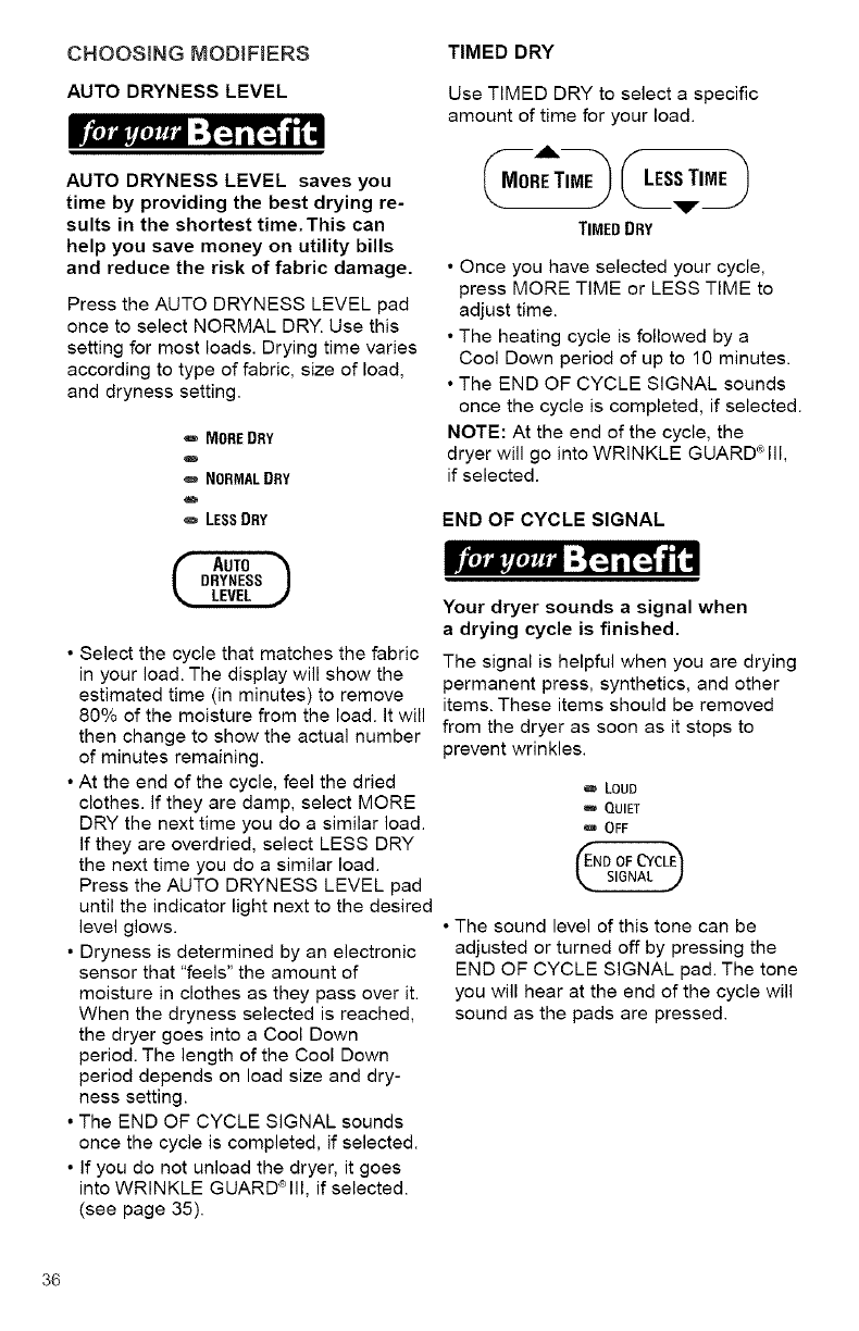
TIMED DRY
Use TIMED DRY to select a specific
amount of time for your load.
• Once you have selected your cycle,
press MORE TIME or LESS TIME to
adjust time.
• The heating cycle is followed by a
Cool Down period of up to 10 minutes.
• The END OF CYCLE SIGNAL sounds
once the cycle is completed, if selected.
NOTE: At the end of the cycle, the
dryer will go into WRINKLE GUARD®Ill,
if selected.
END OF CYCLE SIGNAL
iVttlili_lti_til it=.] i[_ ilil
Your dryer sounds a signal when
a drying cycle is finished.
The signal is helpful when you are drying
permanent press, synthetics, and other
items. These items should be removed
from the dryer as soon as it stops to
prevent wrinkles.
o LOUD
QUIET
w OFF
• The sound level of this tone can be
adjusted or turned off by pressing the
END OF CYCLE SIGNAL pad. The tone
you will hear at the end of the cycle will
sound as the pads are pressed.
36
CHANGINGCYCLES/OPTIONS/
MODIFIERS
TheCycles,OptionsandModifiers
selectedmaybechangedanytime
beforeSTARTispressed.Asingleshort
tonewillsoundwhenaselectionis
made.Ifanunavailablecombinationis
selected,threeshorttoneswillsound
andthelastselectionwillnotbe
accepted.
TochangeOptions/Modifiers:
TheOptionsandModifierscan
beadjustedpriortotheevent occurring.
STEP 1. Press STOP/CANCEL once.
This will stop the dryer.
STEP 2. Select desired Options and/or
Modifiers.
STEP 3. Press START to restart the
dryer.
To change cycles:
STEP 1. Press STOP/CANCEL twice.
STEP 2. Select desired cycle.
STEP 3. Press START to restart the
dryer at the beginning of the new cycle.
if you do not press START within
5 minutes of selecting the cycle, the
dryer will automatically shut off.
37
OPERATING CONTROLS
START
Use this control to start the dryer. Be sure
the dryer door is closed. Opening the
door stops the dryer. It will not start again
until you close the door and press START.
NOTE: If you do not close the dryer door
and press START within 5 minutes of
when the dryer door was opened, the
dryer will shut off. You will have to select a
new cycle to restart the dryer.
STOP/CANCEL
Use this control to temporarily stop
(pause) the cycle.
*If STOP/CANCEL is pressed once and
you open the dryer door, you must close
the door and press START to restart the
dryer (see NOTE above).
, If STOP/CANCEL is pressed once and
you leave the dryer door closed, you can
press START to continue the cycle.
To cancel the cycle, press
STOP/CANCEL twice. Pressing
STOP/CANCEL will not erase the
CUSTOM SET settings.
INDICATOR LIGHTS
CYCLE LIGHTS
Located next to each pad under SELECT
CYCLE, these lights show the cycle you
have selected.
DISPLAY LIGHTS
These lights show the level of dryness
selected, temperature settings and
estimated or actual drying time.
OPTIONS LIGHTS
These lights show when DAMP DRY
SIGNAL , WRINKLE GUARD {_III or
TOUCH UP have been selected.
STATUS LIGHTS
Located on the right side of the console,
these lights show what portion of the
cycle the dryer is operating.
DRYER STATUS
oDRYING
wCOOL DOWN
mWRINKLE GHARR
CHECK LINT SCREEN
CHECK LINT SCREEN
Wt,.Imtmm, t.Ir..] i[_ 1[-"
A properly cleaned lint screen will
allow your dryer to operate at peak
efficiency. This can reduce your utility
bills and extend the life of your dryer.
Once a cycle is selected, the CHECK
LINT SCREEN light will flash to remind
you to clean the lint screen. The light will
flash for up to 5 minutes, or until the door
is opened, or START is pressed.
Clean the lint screen before starting each
load. If you do not, your dryer may not op-
erate properly.
38
TUMBLE FREETM HEATED
DRYER RACK
The dry rack was shipped on top
of your dryer. Remove and discard
shipping blocks before using.
_leJo_teJ_o "Iq i[_ _o
Use the TUMBLE FREE TM Heated Dryer
Rack for items that you do not want to
tumble dry, such as sweaters and
tennis shoes. When you use the
heated dryer rack, the heated air inside
the dryer flows in a concentrated
pattern to allow efficient and uniform
drying. Use TIMED DRY to select the
desired time.
To use the heated dryer rack:
Do not remove lint screen.
STEP 1. Open dryer door.
STEP 2. Slide dryer rack over the bottom
of the dryer door opening. Push down to
secure it on the frame.
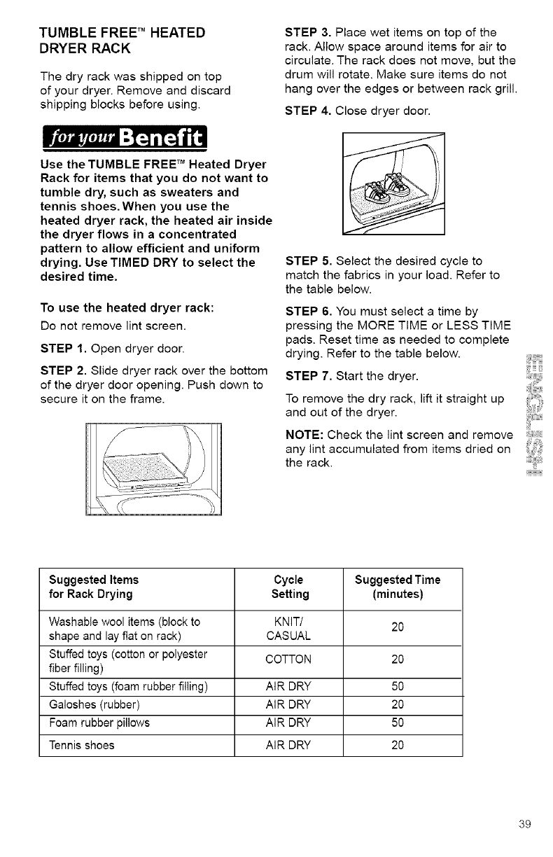
STEP 3. Place wet items on top of the
rack. Allow space around items for air to
circulate. The rack does not move, but the
drum will rotate. Make sure items do not
hang over the edges or between rack grill.
STEP 4. Close dryer door.
STEP 5. Select the desired cycle to
match the fabrics in your load. Refer to
the table below.
STEP 6. You must select a time by
pressing the MORE TIME or LESS TIME
pads. Reset time as needed to complete
drying. Refer to the table below.
STEP 7. Start the dryer.
To remove the dry rack, lift it straight up
and out of the dryer.
NOTE: Check the lint screen and remove
any lint accumulated from items dried on
the rack.
Suggested Items Cycle Suggested Time
for Rack Drying Setting (minutes)
Washable wool items (block to KNIT/ 20
shape and lay fiat on rack) CASUAL
Stuffed toys (cotton or polyester COTTON 20
fiber filling)
Stuffed toys (foam rubber filling) AIR DRY 50
Galoshes (rubber) AIR DRY 20
Foam rubber pillows AIR DRY 50
Tennis shoes AIR DRY 20
39
TOTAL CARE TM SYSTEM
The exclusiveTOTAL CARE TM
SYSTEM combines the KING SIZE TM
load capacity, EVENHEAT _ ,
WRINKLE GUARD '_ Ill, and the
TUMBLE FREE TM heated dryer rack to
ensure total drying care for any type of
fabric and load size.
EVENHEAT TM Drying System
The EVENHEAT TM Drying System uses a
solid-state sensor to prevent the large
variations in drying temperatures that
occur in most other dryers. More
consistent, even heat in every cycle
results in better fabric care by shortening
drying times and by maintaining lower
drying temperatures.
"SMART" COOL DOWN PERIOD
Once the selected level of dryness
is reached, the dryer goes into a cool
down period lasting 1-10 minutes. Unlike
other dryers which provide a fixed
1g-minute coo! down, this "smart" cool
down period is based on the temperature
of the clothes in your load and varies the
time accordingly.
*For small loads or loads that are dried
at a lower temperature, the cool down
period will be reduced to as low as one
minute.
• For large loads or loads that are dried
at a high temperature, the cool down
period will be closer to ten minutes.
4O
PREPARING CLOTHES SORTING CLOTHES
FOR DRYING
_i'zeJJl_zeJ_="I:-] i1_ iT["
Follow these recommendations
to help save on your utility bills and
prolong the life of your garments.
•Refer to your Washer Owner's Manual
for proper washing techniques and
additional laundry tips.
• See page 5 of this manual for
Important Safety Instructions.
DRYING TIPS
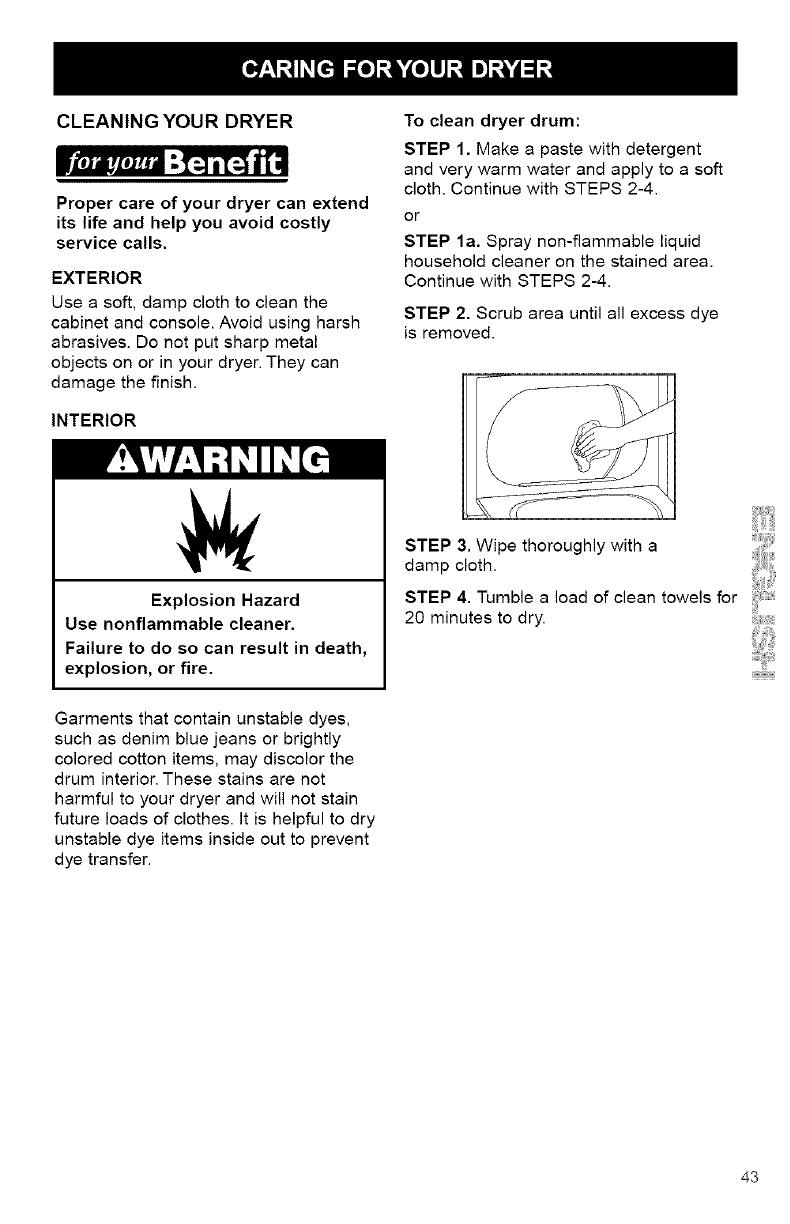
• Close zippers, snaps, and hooks to
avoid snagging other items. Remove
heat-sensitive trim that can be damaged
by drying. Tie strings and sashes so they
will not tangle.
• Check garments for spots and stains left
after washing. Do not tumble these
items. Heat may permanently set stains.
• Check pockets before drying. Sharp
or metal objects can damage your
dryer. Do not lay these objects on
your dryer, they can damage the
finish. Turn pockets of heavy items
inside out for even drying.
• Place small items such as baby
socks or hankies in laundry bag for easy
removal.
• Articles to be ironed should be
removed while still damp.
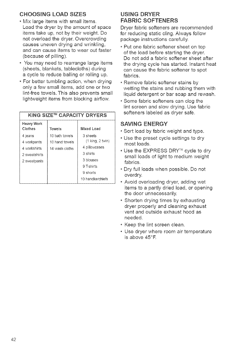
•Separate dark colors from light colors,
colorfast from non-colorfast. Items prop-
erly sorted by color for washing
are usually properly sorted for drying.
• Separate heavy fabrics (denim,
towels) from light fabrics (synthetics,
permanent press).
• Separate lint givers (towels, chenille)
from lint takers (corduroy, synthetics,
permanent press). When possible,
turn lint takers inside out.
41
CHOOSINGLOADSIZES
•Mixlargeitemswithsmallitems.
Loadthedryerbytheamountofspace
itemstakeup,notbytheirweight.Do
notoverloadthedryer.Overcrowding
causesunevendryingandwrinkling,
andcancauseitemstowearoutfaster
(becauseofpilling).
•You may need to rearrange large items
(sheets, blankets, tablecloths) during
a cycle to reduce bailing or rolling up.
•For better tumbling action, when drying
only a few small items, add one or two
lint-free towels. This also prevents small
lightweight items from blocking airflow.
KING SIZE TM CAPACITY DRYERS
Heavy Work
Clothes
4 jeans
4 workpants
4 workshirts
2 sweatshirts
2 sweatpants
Towels
10 bath towels
10 hand towels
14 wash cloths
Mixed Load
3 sheets
(1 king, 2 twin)
4 pillowcases
3 shirts
3 blouses
91--sh4rts
9 shorts
10 handkercNefs
USING DRYER
FABRIC SOFTENERS
Dryer fabric softeners are recommended
for reducing static cling. Always follow
package instructions carefully.
*Put one fabric softener sheet on top
of the load before starting the dryer.
Do not add a fabric softener sheet after
the drying cycle has started. Instant heat
can cause the fabric softener to spot
fabrics.
, Remove fabric softener stains by
wetting the stains and rubbing them with
liquid detergent or bar soap and rewash.
Some fabric softeners can clog the
lint screen and slow drying. Use fabric
softeners labeled as dryer safe.
SAVING ENERGY
• Sort load by fabric weight and type.
•Use the preset cycle settings to dry
most loads.
•Use the EXPRESS DRY TM cycle to dry
small leads of light to medium weight
fabrics.
•Dry fu!! loads when possible. Do not
overdry.
•Avoid overloading dryer, adding wet
items to a partly dried load, or opening
the door unnecessarily.
Shorten drying times by exhausting
dryer properly and cleaning exhaust
vent and outside exhaust hood as
needed.
Keep the lint screen clean.
• Use dryer where room air temperature
is above 45°R
42
CLEANING YOUR DRYER
Proper care of your dryer can extend
its life and help you avoid costly
service calls.
EXTERIOR
Use a soft, damp cloth to clean the
cabinet and console. Avoid using harsh
abrasives. Do not put sharp metal
objects on or in your dryer. They can
damage the finish.
INTERIOR
To clean dryer drum:
STEP 1. Make a paste with detergent
and very warm water and apply to a soft
cloth. Continue with STEPS 2-4.
or
STEP la. Spray non-flammable liquid
household cleaner on the stained area.
Continue with STEPS 2-4.
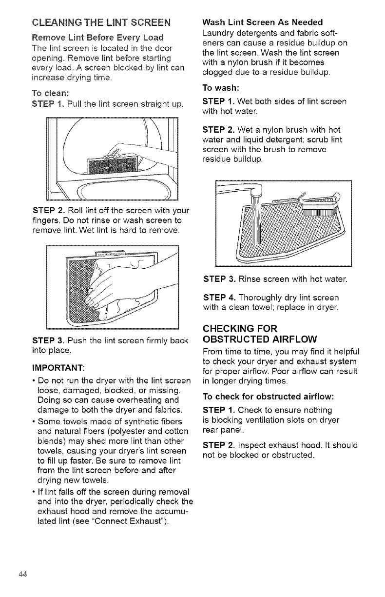
STEP 2. Scrub area until all excess dye
is removed.
Explosion Hazard
Use nonflammable cleaner.
Failure to do so can result in death,
explosion, or fire.
Garments that contain unstable dyes,
such as denim blue jeans or brightly
colored cotton items, may discolor the
drum interior. These stains are not
harmful to your dryer and will not stain
future loads of clothes. It is helpful to dry
unstable dye items inside out to prevent
dye transfer.
STEP 3. Wipe thoroughly with a
damp cloth.
STEP 4. Tumble a load of clean towels for
20 minutes to dry.
43
CLEANING THE LINT SCREEN
Remove Lint Before Every Load
The lint screen is located in the door
opening. Remove lint before starting
every load. A screen blocked by lint can
increase drying time,
To clean:
STEP 1. Pull the lint screen straight up,
STEP 2. Roll lint off the screen with your
fingers. Do not rinse or wash screen to
remove lint. Wet lint is hard to remove.
STEP 3. Push the lint screen firmly back
into place.
IMPORTANT:
• Do not run the dryer with the lint screen
loose, damaged, blocked, or missing.
Doing so can cause overheating and
damage to both the dryer and fabrics.
• Some towels made of synthetic fibers
and natural fibers (polyester and cotton
blends) may shed more lint than other
towels, causing your dryer's lint screen
to fill up faster. Be sure to remove lint
from the lint screen before and after
drying new towels.
• If lint falls off the screen during removal
and into the dryer, periodically check the
exhaust hood and remove the accumu-
lated lint (see "Connect Exhaust").
Wash Lint Screen As Needed
Laundry detergents and fabric soft-
eners can cause a residue buildup on
the lint screen. Wash the lint screen
with a nylon brush if it becomes
clogged due to a residue buildup.
To wash:
STEP 1. Wet both sides of lint screen
with hot water.
STEP 2. Wet a nylon brush with hot
water and liquid detergent; scrub lint
screen with the brush to remove
residue buildup.
STEP 3. Rinse screen with hot water.
STEP 4. Thoroughly dry lint screen
with a clean towel; replace in dryer.
CHECKING FOR
OBSTRUCTED AIRFLOW
From time to time, you may find it helpful
to check your dryer and exhaust system
for proper airflow. Poor airflow can result
in longer drying times.
To check for obstructed airflow:
STEP 1. Check to ensure nothing
is blocking ventilation slots on dryer
rear panel.
STEP 2. Inspect exhaust hood. It should
not be blocked or obstructed.
44
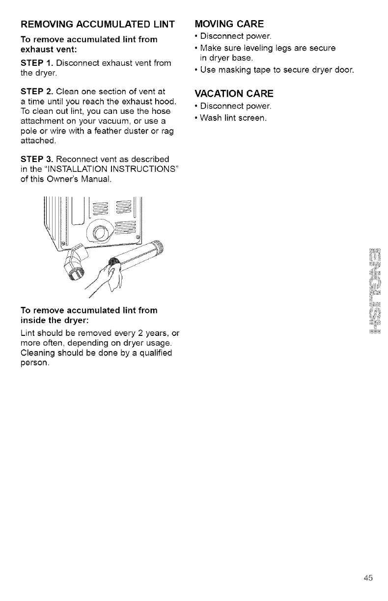
REMOVINGACCUMULATEDLINT
Toremoveaccumulatedlintfrom
exhaustvent:
STEP1.Disconnectexhaustventfrom
thedryer.
STEP2.Cleanonesectionofventat
atimeuntilyoureachtheexhausthood.
Tocleanoutlint,youcanusethehose
attachmentonyourvacuum,orusea
poleorwirewithafeatherdusterorrag
attached.
STEP3.Reconnectventasdescribed
inthe"INSTALLATIONINSTRUCTIONS"
ofthisOwner'sManual.
MOVINGCARE
•Disconnectpower.
•Makesurelevelinglegsare secure
in dryer base.
• Use masking tape to secure dryer door.
VACATION CARE
• Disconnect power.
• Wash lint screen.
To remove accumulated lint from
inside the dryer:
Lint should be removed every 2 years, or
more often, depending on dryer usage.
Cleaning should be done by a qualified
person.
45
46
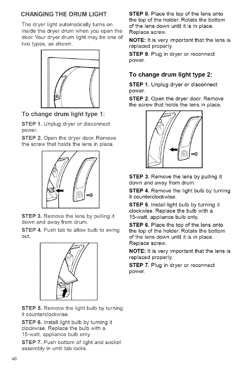
CHANGING THE DRUM LIGHT
The dryer light automatically turns on
inside the dryer drum when you open the
door. Your dryer drum light may be one of
two types, as shown.
To change drum light type 1:
STEP 1. Unplug dryer or disconnect
power.
STEP 2. Open the dryer door. Remove
the screw that holds the lens in )lace.
STEP 3. Remove the lens by pulling it
down and away from drum.
STEP 4. Push tab to allow bulb to swing
out.
STEP 5. Remove the light bulb by turning
it counterclockwise.
STEP 6. Install light bulb by turning it
clockwise. Replace the bulb with a
15-watt, appliance bulb only.
STEP 7, Push bottom of light and socket
assembly in until tab locks.
STEP 8. Place the top of the lens onto
the top of the holder. Rotate the bottom
of the lens down until it is in place.
Replace screw.
NOTE: It is very important that the lens is
replaced properly.
STEP 9. Plug in dryer or reconnect
power.
To change drum light type 2:
STEP 1. Unplug dryer or disconnect
power.
STEP 2. Open the dryer door. Remove
the screw that holds the lens in place.
STEP 3. Remove the lens by pulling it
down and away from drum.
STEP 4. Remove the light bulb by turning
it counterclockwise.
STEP 5. Install light bulb by turning it
clockwise. Replace the bulb with a
15-watt, appliance bulb only.
STEP 6. Place the top of the lens onto
the top of the holder. Rotate the bottom
of the lens down until it is in place.
Replace screw.
NOTE: It is very important that the lens is
replaced properly.
STEP 7. Plug in dryer or reconnect
power.
IVt'_im,'t'_,'_a"-I_i1=%_I,,m
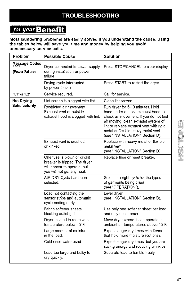
Most laundering problems are easily solved if you understand the cause. Using
the tables below will save you time and money by helping you avoid
unnecessary service calls.
Problem Possible Cause
Message Codes
"PF" Dryer connected to power supply
(Power Failure} during installation or power
failure.
Drying cycle interrupted
by power failure.
"El" or "E2" Service required.
Not Drying Lint screen is clogged with lint.
Satisfactorily Restricted air movement.
Exhaust vent or outside
exhaust hood is clogged with lint.
8olution
Press STOP/CANCEL to clear display.
Press STARTto restart the dryer.
Call for service.
Clean Iint screen.
Run dryer for 5-10 minutes. Hold
hand under outside exhaust hood to
check air movement. If you do not feel
air moving, clean exhaust system of
Iint or replace exhaust vent with rigid
metal or flexible heavy metal vent
(see "INSTALLATION," Section D).
Exhaust vent is crushed Replace with heavy metal or flexible
or kinked, metal vent
(see "INSTALLATION," Section D).
One fuse is blown or circuit Replace fuse or reset breaker.
breaker is tripped. The dryer
will appear to operate, but
you will not get any heat.
AIR DRY Cycle has been Select the right cycle for the types
selected, of garments being dried
(see "OPERATION").
Load not contacting the Level dryer
sensor strips and automatic (see "INSTALLATION," Section B).
cycle ending early.
Fabric softener sheets Use only one softener sheet per load
blocking outlet grill, and only use it once.
Dryer located in room with Move dryer where it can operate in
temperature below 45°R ambient air temperatures above 45°R
Large amount of moisture Expect longer dry times with items
in the load. that hold more moisture (cottons).
Cold rinse water used. Expect longer dry times, but you are
saving energy and reducing wrinkles.
Load too large and bulky to Separate Ioad to tumble freely.
dry quickly.
47
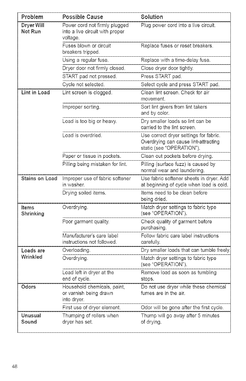
Problem Possible Cause 8olution
Dryer WHI Power cord not firmly ptugged PJug power cord into a live circuit.
Not Run into a live circuit with proper
vottage.
Fuses blown or circuit Replace fuses or reset breakers.
breakers tripped.
Using a regular fuse. Replace with a time-delay fuse.
Dryer door not firmly closed. Close dryer door tightly.
START pad not pressed. Press START pad.
Cycle not selected. Select cycle and press START pad.
Lint in Load Lint screen is clogged. Clean lint screen. Check for air
movement.
Improper sorting. Sort lint givers from lint takers
and by color.
Load is too big or heavy. Dry smaller loads so lint can be
carried to the lint screen.
Load is overdried. Use correct dryer settings for fabric.
Overdrying can cause lint-attracting
static (see "OPERATION").
Paper or tissue in pockets. Clean out pockets before drying.
Pilling being mistaken for lint. Pilling (surface fuzz) is caused by
normal wear and laundering.
Stains on Load Improper use of fabric softener Use fabric softener sheets in dryer. Add
in washer, at beginning of cycle when load is cold.
Drying soiled items. Items need to be clean before
being dried.
totems Overdrying. Match dryer settings to fabric type
Shrinking (see "OPERATION").
Poor garment quaJity. Check quality of garment before
purchasing.
Manufacturer's care label Fottow fabric care label instructions
instructions not followed, carefully.
Loads are Overloading. Dry smaller loads that can tumble freeJ
WrinMed Overdrying. Match dryer settings to fabric type
(see "OPERATION").
Load teft in dryer at the Remove Joad as soon as tumbling
end of cycle, stops.
Odors HousehoJd chemicals, paint, Do not use dryer whiJe these chemicaJ
or varnish being drawn fumes are in the air.
into dryer.
First use of dryer element. Odor wilt be gone after the first cycle.
Unusua_ Thumping of rotters when Thump will go away after 5 minutes
Sound dryer has set. of drying.
48
KENMORE ELITE TM DRYERS
"We Service What We Sell" is our assurance that you can depend on Sears for
service. Your Kenmore ELITE TM appliance has added value when you consider that
Sears has service units nationwide, staffed with professional technicians trained on all
appliances Sears sells. They have the knowledge and skills, tools, parts, and
equipment to ensure our pledge to you that "We Service What We Sell."
Maintain the value of your purchase with a Sears Maintenance Agreement. Kenmore
ELITE TM appliances are designed, manufactured, and tested for years of dependable
operation. Yet, any appliance may require service from time to time. The Sears
Maintenance Agreement offers you an outstanding service program for your product.
The Sears Maintenance Agreement:
•Is your way to buy tomorrow's service at today's prices.
• Eliminates repair bills resulting from normal use.
• Allows for as many service calls as required.
• Provides an annual Preventive Maintenance Check at your request to keep your
dryer in proper running condition.
For more information call:
1-800-827-6655
49

50

For in-home major brand repair service:
Call 24 hours a day, 7 days a week
1-800-4-MY-HOME _' (1-800-469-4663)
Para pedir servicio de reparacibn - 1-800-676-5811
Au Canada pour tout le service - 1-877-LE-FOYER _M(1-877-533-6937)
For the repair or replacement parts you need:
Call 6 a.m. -11 p.m. CST, 7 days a week
PartsDirect
1-800-366-PART (1-800-366-7278)
www.sears.com/partsdirect
Para ordenar piezas - 1-800-659-7084
For a Sears Service Center location in your area:
Call 24 hours aday, 7days a week
1-800-488-1222
For a Sears Maintenance Agreement purchase or inquiry:
Call 7 a.m. - 5 p.m. CST, Monday - Saturday
1-800-827-6655
