Kenmore 11062982101 User Manual ELECTRIC DRYER Manuals And Guides L0305405
KENMORE Residential Dryer Manual L0305405 KENMORE Residential Dryer Owner's Manual, KENMORE Residential Dryer installation guides
User Manual: Kenmore 11062982101 11062982101 KENMORE ELECTRIC DRYER - Manuals and Guides View the owners manual for your KENMORE ELECTRIC DRYER #11062982101. Home:Laundry & Garment Care Parts:Kenmore Parts:Kenmore ELECTRIC DRYER Manual
Open the PDF directly: View PDF ![]() .
.
Page Count: 37
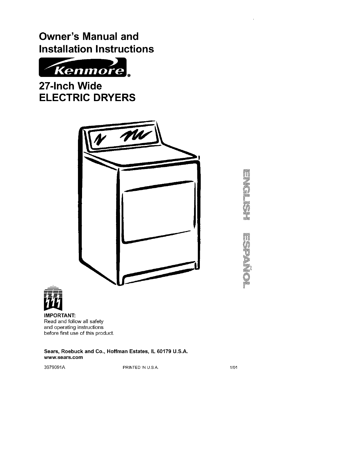
Owner's Manual and
Installation Instructions
27-Inch Wide
ELECTRIC DRYERS
im rmm
IMPORTANT:
Read and follow all safety
and operating instructions
before first use of this product.
Sears, Roebuck and Co., Hoffman Estates, IL 60179 U.S.A.
www.sears.com
3979091A PRINTED IN U.S.A. 1/01
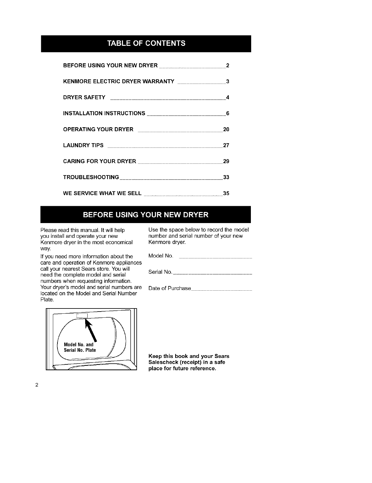
BEFORE USING YOUR NEW DRYER 2
KENMORE ELECTRIC DRYER WARRANTY 3
DRYER SAFETY ...... 4
INSTALLATION INSTRUCTIONS 6
OPERATING YOUR DRYER 2O
LAUNDRY TIPS ...... 27
CARING FOR YOUR DRYER 29
TROUBLESHOOTING ..... 33
WE SERVICE WHAT WE SELL 35
Please read this manual. It will help
you install and operate your new
Kenmore dryer in the most economical
way.
If you need more information about the
care and operation of Kenmore appliances
call your nearest Sears store. You will
need the complete model and serial
numbers when requesting information.
Your dryer's model and serial numbers are
located on the Model and Sedal Number
Plate.
ModelNo.and
SerialNo. Plate
Use the space below to record the model
number and serial number of your new
Kenmore dryer.
Model No.
Serial No.....
Date of Purchase
Keep this book and your Sears
Salescheck (receipt) in a safe
place for future reference.
Full One Year Warranty on
Mechanical and Electrical Parts
For one year from the date of purchase,
if this dryer is installed and operated
according to the instructions in this manu-
al, Sears will repair or replace any of its
mechanical or electrical parts if they are
defective in material or workmanship.
NOTE: Exhausting your dryer with
a plastic vent may void this warranty,
See "Installation Instructions" for the
complete exhaust requirements for this
dryer.
Warranty Restriction
If the dryer is subjected to other than
private family use, all warranty coverage is
effective for only 90 days.
Warranty Service
Warranty service is available by contacting
your nearest Sears Service Center in the
United States.
This warranty applies only while this dryer
is in use in the United States.
This warranty gives you specific legal
rights, and you may also have other rights
which vary from state to state,
Sears, Roebuck and Co., Dept. 817WA,
Hoffman Estates, IL 60179.
For Sears Warranty information or to contact a
Sears Service Center, please reference the service
numbers located on the back page of this manual
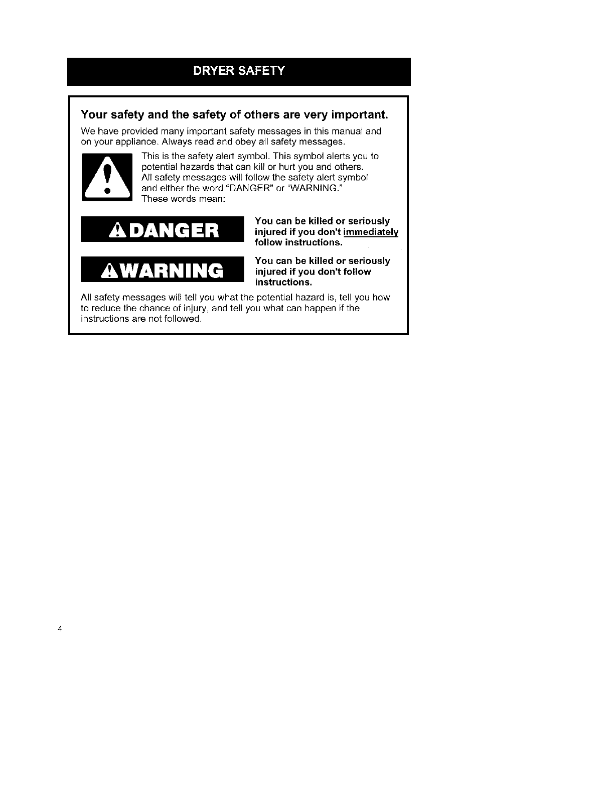
Your safety and the safety of others are very important.
We have provided many important safety messages in this manual and
on your appliance. Always read and obey all safety messages.
This is the safety alert symbol. This symbol alerts you to
potential hazards that can kill or hurt you and others.
All safety messages will follow the safety alert symbol
and either the word "DANGER" or "WARNING."
These words mean:
You can be killed or seriously
injured if you don't immediately
follow instructions.
You can be killed or seriously
injured if you don't follow
instructions.
All safety messages will tell you what the potential hazard is, tell you how
to reduce the chance of injury, and tell you what can happen if the
instructions are not followed.
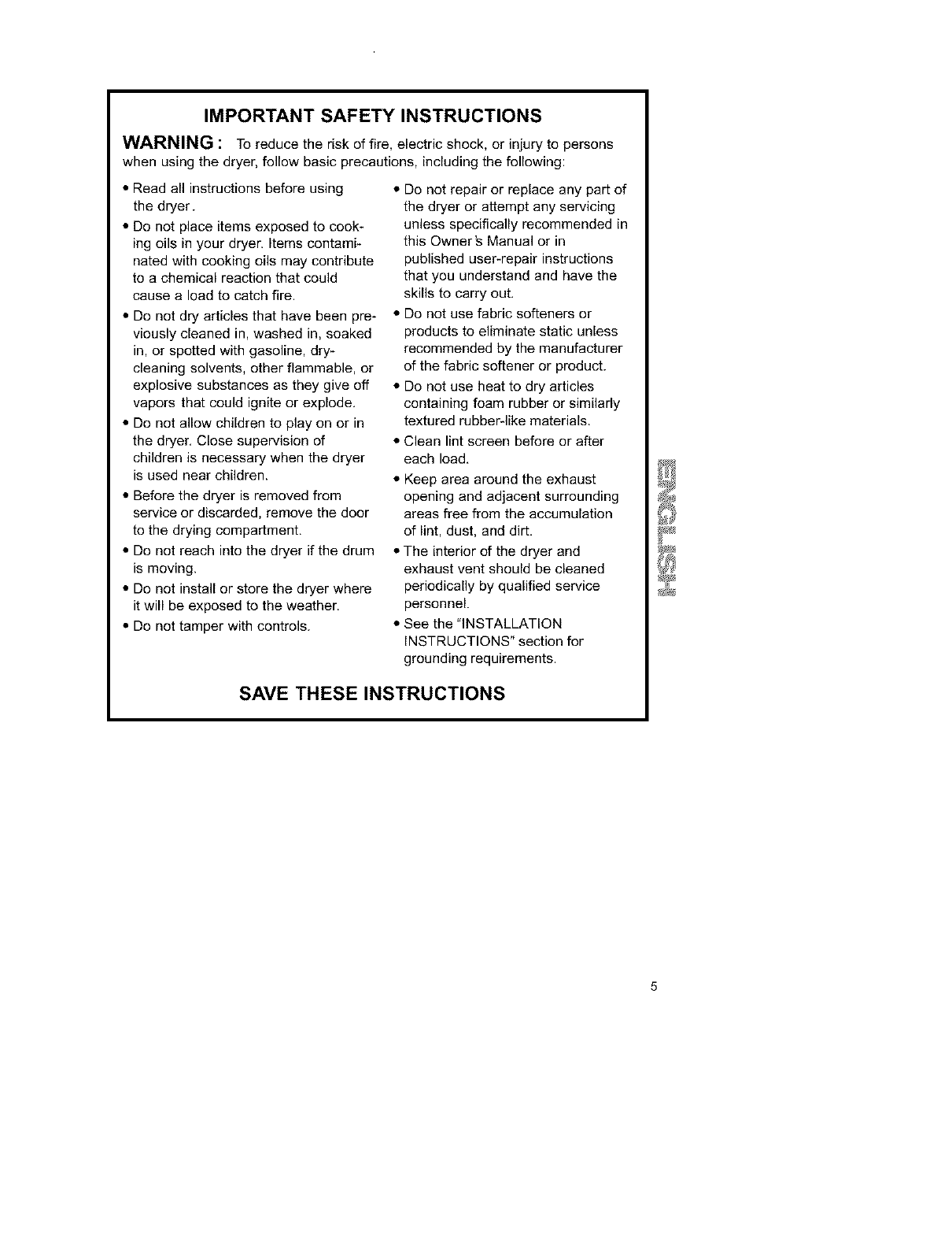
IMPORTANT SAFETY INSTRUCTIONS
WARNING: Toreducethe riskof fire, electricshock,or injurytopersons
when using the dryer, follow basic precautions, including the following:
• Read all instructions before using • Do not repair or replace any part of
the dryer.
• Do not place items exposed to cook-
ing oils in your dryer. Items contami_
nated with cooking oils may contribute
to a chemical reaction that could
cause aload to catch fire.
• Do not dry articles that have been pre-
viously cleaned in, washed in, soaked
in, or spotted with gasoline, dry_
cleaning solvents, other flammable, or
explosive substances as they give off
vapors that could ignite or explode,
• Do not allow children to play on or in
the dryer, Close supervision of
children is necessary when the dryer
is used near children.
• Before the dryer is removed from
service or discarded, remove the door
to the drying compartment,
• Do not reach into the dryer if the drum
is moving.
• Do not install or store the dryer where
it will be exposed to the weather.
• Do not tamper with controls.
the dryer or attempt any servicing
unless specifically recommended in
this Owner _ Manual or in
published user-repair instructions
that you understand and have the
skills to carry out.
• Do not use fabric softeners or
products to eliminate static unless
recommended by the manufacturer
of the fabric softener or product.
• Do not use heat to dry articles
containing foam rubber or similarly
textured rubber-like materials.
• Clean lint screen before or after
each load.
• Keep area around the exhaust
opening and adjacent surrounding
areas free from the accumulation
of lint, dust, and dirt.
• The interior of the dryer and
exhaust vent should be cleaned
periodically by qualified service
personnel.
• See the "INSTALLATION
INSTRUCTIONS" section for
grounding requirements.
SAVE THESE INSTRUCTIONS
Tools and Parts
Check that you have everything neces-
sary for correct installation, Proper
installation is your responsibility.
• flat*blade screwdriver
• adjustable wrench that opens to 1 in.
or hex_head socket wrench (for
adjusting dryer feet)
• level
• wire stripper (direct wire installations)
• #2 Phillips screwdriver
• safety glasses
• duct tape
• caulking gun and compound (for
installing new exhaust vent)
• gloves
• tin snips (new vent installations)
Parts supplied:
Remove parts package from dryer drum.
Check that all parts were included.
4_veling legs
Parts needed:
Check local codes, check existing
electrical supply and venting and see
"Electrical Requirements" and "Venting
Requirements" before purchasing parts.
Mobile home installations require:
• Metal exhaust system hardware
available for purchase from your local
Sears store or Sears Service Center.
Location Requirements
Explosion Hazard
Keep flammable materials and vapors,
such as gasoline, away from dryer.
Place dryer at least 18 inches (46 cm)
above the floor for a garage
installation.
Failure to do so can result in death,
explosion, or fire.
You will need
•A location that allows for proper
exhaust installation. See "Venting
Requirements."
• A separate 30 amp circuit.
• A grounded electrical outlet located
within 2 ft (61 cm) of either side of the
dryer, See "Electrical Requirements,"
• A sturdy floor to support the total dryer
weight of 200 Ibs (90.7 kg).
• A level floor with a maximum slope of 1
in. (2.5 cm) under entire dryer. (If slope
is greater than 1 in, [2.5 cm], install
Extended Dryer Feet kit, Part No,
279810.) Clothes may not tumble prop-
erly and models with automatic sensor
cycles may not operate correctly if
dryer is not level.
Do not operate your dryer at tempera-
tures below 45°F (7°C). At lower temper-
atures, the dryer might not shut off at the
end of an automatic cycle. Drying times
can be extended.
Install the dryer where it is protected from
water and/or weather.
Check code requirements. Some codes
limit, or do not permit, installation of the
dryer in garages, closets, mobile homes,
or sleeping quarters. Contact your local
building inspector.
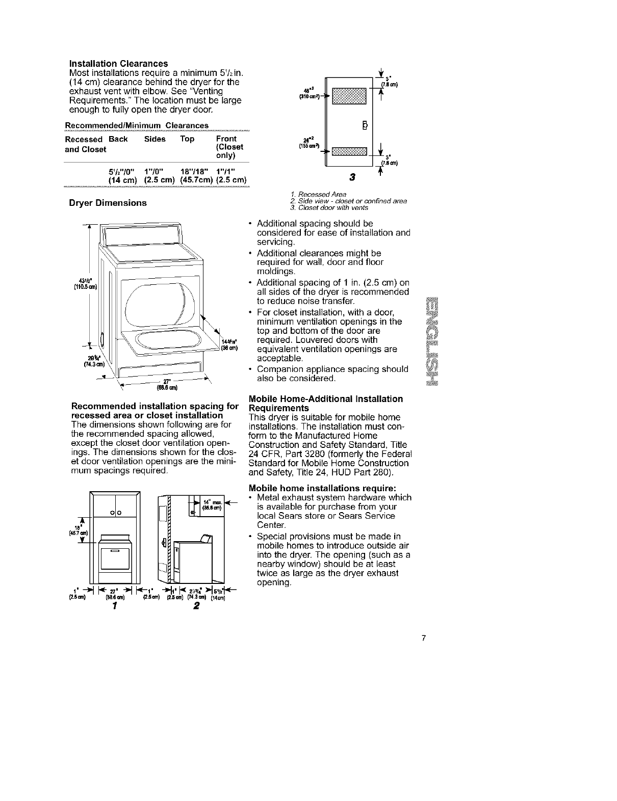
Installation Clearances
Most installations require a minimum 5/2in.
(14 cm) clearance behind the dryer for the
exhaust vent with elbow. See "Venting
Requirements." The location must be large
enough to fully open the dryer door.
Recommended/Minimum Clearances
Recessed Back Sides Top Front
and Closet (Closet
only)
5V2"/0" 1"/0" 18"/18" 1"/1"
(14 cm) (2.5 cm) (45.7cm) (2.5 cm)
Dryer Dimensions
_i_,
(743ore)
1_m)
Recommended installation spacing for
recessed area or closet installation
The dimensions shown following are for
the recommended spacing allowed,
except the closet door ventilation open-
ings. The dimensions shown for the clos-
et door ventilation openings are the mini-
mum spacings required.
(_,7=.)
3[_
1,-)
Cs=n)
14 rt_(.
_1 (_.8 _) _--
olo
I2
_t.ecm)
48 "l
($10Qazj- _1_
24 "2
_.s a'nI
3
1. Recessed Area
2. Side view -closet or confined area
3. Closet door with vents
•Additional spacing should be
considered for ease of installation and
servicing.
• Additional clearances might be
required for wall, door and floor
moldings.
• Additional spacing of 1 in. (2.5 cm) on
all sides of the dryer is recommended
to reduce noise transfer.
• For closet installation, with a door,
minimum ventilation openings in the
top and bottom of the door are
required. Louvered doors with
equivalent ventilation openings are
acceptable.
• Companion appliance spacing should
also be considered.
Mobile Home-Additional Installation
Requirements
This dryer is suitable for mobile home
installations. The installation must con-
form to the Manufactured Home
Construction and Safety Standard, Title
24 CFR, Part 3280 (formerly the Federal
Standard for Mobile Home Construction
and Safety, Title 24, HUD Part 280).
Mobile home installations require:
• Metal exhaust system hardware which
is available for purchase from your
local Sears store or Sears Service
Center.
• Special provisions must be made in
mobile homes to introduce outside air
into the dryer, The opening (such as a
nearby window) should be at least
twice as large as the dryer exhaust
opening.
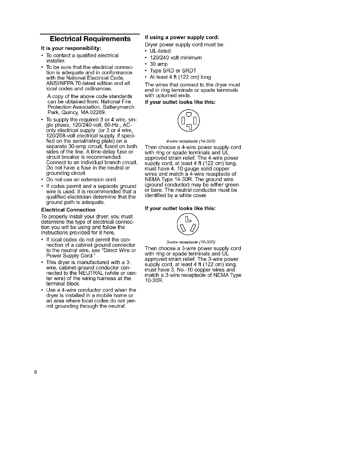
Electrical Requirements
It is your responsibility:
•To contact a qualified electrical
installer.
• To be sure that the electrical connec*
tion is adequate and in conformance
with the National Electrical Code,
ANSI/NFPA 70-latest edition and all
local codes and ordinances,
A copy of the above code standards
can be obtained from: National Fire
Protection Association, Batterymarch
Park, Quincy, MA 02269.
• To supply the required 3 or 4 wire, sin-
gle phase, 120/240-volt, 60-Hz., AC-
only electrical supply (or 3 or 4 wire,
120/208-volt electrical supply, if speci-
fied on the serial/rating plate) on a
separate 30-amp circuit, fused on both
sides of the line. A time-delay fuse or
circuit breaker is recommended.
Connect to an individual branch circuit.
Do not have a fuse in the neutral or
grounding circuit.
• Do not use an extension cord.
• If codes permit and a separate ground
wire is used, it is recommended that a
qualified electrician determine that the
ground path is adequate.
Electrical Connection
To properly install your dryer, you must
determine the type of electrical connec-
tion you will be using and follow the
instructions provided for it here.
• If local codes do not permit the con-
nection of a cabinet ground connector
to the neutral wire, see "Direct Wire or
Power Supply Cord."
• This dryer is manufactured with a 3-
wire, cabinet-ground conductor con-
nected to the NEUTRAL (white or cen-
ter wire) of the wiring harness at the
terminal block.
• Use a 4-wire conductor cord when the
dryer is installed in a mobile home or
an area where local codes do not per-
mit grounding through the neutral.
If using apower supply cord:
Dryer power supply cord must be:
•ULqisted
• 120/240 volt minimum
• 30 amp
• Type SRD or SRDT
• At least 4 ft (122 cm) long
The wires that connect to the dryer must
end in ring terminals or spade terminals
with upturned ends,
If your outlet looks like this:
©
4-wire receptacle (14-30R)
Then choose a 4-wire power supply cord
with ring or spade terminals and UL
approved strain relief. The 4-wire power
supply cord, at least 4 ft (122 cm) long,
must have 4, 10 gauge solid copper
wires and match a 4-wire receptacle of
NEMA Type 14-30R. The ground wire
(ground conductor) may be either green
or bare. The neutral conductor must be
identified by a white cover.
If your outlet looks like this:
©
3-wire receptacle (10-30R)
Then choose a 3-wire power supply cord
with ring or spade terminals and UL
approved strain relief. The 3-wire power
supply cord, at least 4 ft (122 cm) long,
must have 3, No.*10 copper wires and
match a 3-wire receptacle of NEMA Type
10-30R.
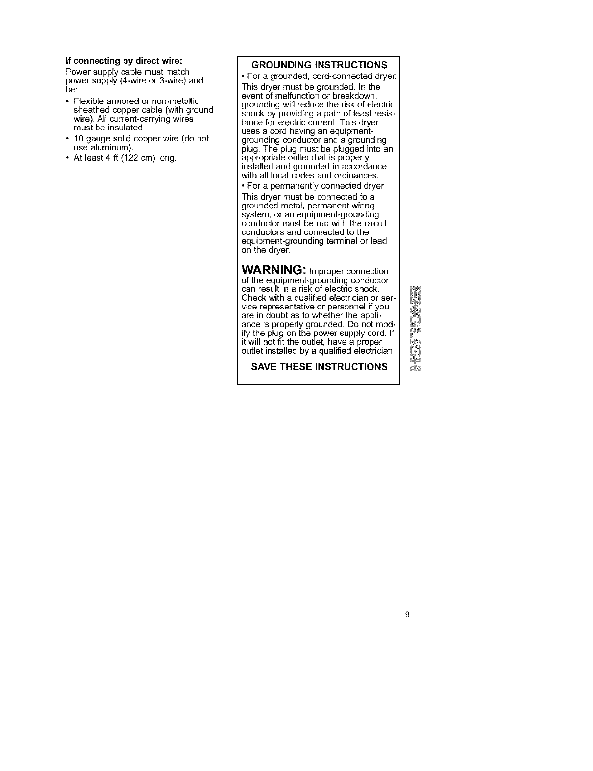
If connecting by direct wire:
Power supply cable must match
power supply (4-wire or 3-wire) and
be:
• Flexible armored or non-metallic
sheathed copper cable (with ground
wire). All current-carrying wires
must be insulated.
• 10 gauge solid copper wire (do not
use aluminum).
• At least 4 ft (122 cm) long.
GROUNDING INSTRUCTIONS
• For a grounded, cord-connected dryer:
This dryer must be grounded. In the
event of malfunction or breakdown,
grounding will reduce the risk of e]ectric
shock by providing a path of least resis-
tance for electric current. This dryer
uses a cord having an equipment-
grounding conductor and a grounding
plug. The plug must be plugged into an
appropriate outlet that is properly
installed and grounded in accordance
with all local codes and ordinances.
• For a permanently connected dryer:
This dryer must be connected to a
grounded metal, permanent wiring
system, or an equipment-grounding
conductor must be run with the circuit
conductors and connected to the
equipment-grounding terminal or lead
on the dryer.
WARNING: Improper connection
of the equipment-grounding conductor
can result in a risk of electric shock.
Check with a qualified electrician or ser-
vice representative or personnel if you
are in doubt as to whether the appli-
ance is properly grounded. De not mod-
ify the plug on the power supply cord. If
it will not fit the outlet, have a proper
outlet installed by aqualified electrician.
SAVE THESE INSTRUCTIONS
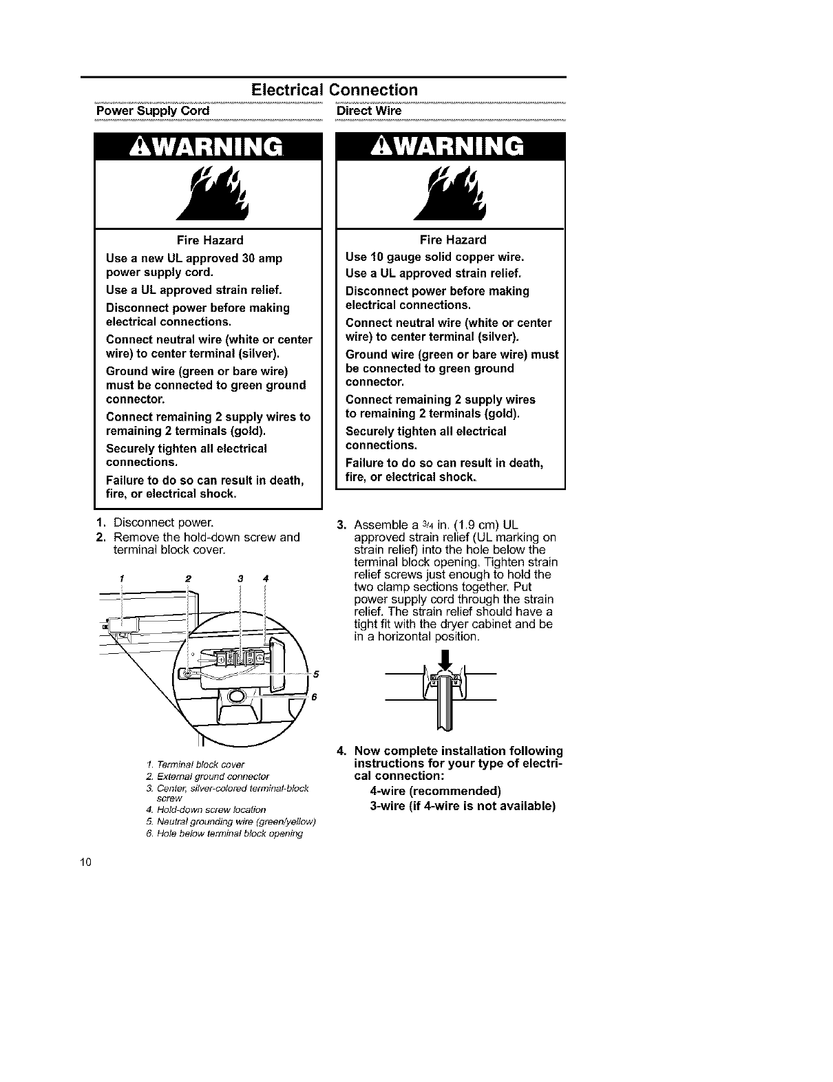
Power Supply Cord
Electrical Connection
Direct Wire
Fire Hazard
Use a new UL approved 30 amp
power supply cord.
Use a UL approved strain relief.
Disconnect power before making
electrical connections.
Connect neutral wire (white or center
wire) to center terminal (silver).
Ground wire (green or bare wire)
must be connected to green ground
connector.
Connect remaining 2 supply wires to
remaining 2 terminals (gold).
Securely tighten all electrical
connections.
Failure to do so can result in death,
fire, or electrical shock.
1. Disconnect power,
2. Remove the hold-down screw and
terminal block cover.
1 2 3 4
1 Terminal block cover
2. Extemal ground connector
3. Center', silver-colored terminal-block
screw
4. Hold-down screw location
5. Neutral grounding wire (green/yellow)
6 Hole below terminal block opening
Fire Hazard
Use 10 gauge solid copper wire.
Use a UL approved strain relief.
Disconnect power before making
electrical connections.
Connect neutral wire (white or center
wire) to center terminal (silver).
Ground wire (green or bare wire) must
be connected to green ground
connector.
Connect remaining 2 supply wires
to remaining 2 terminals (gold).
Securely tighten all electrical
connections.
Failure to do so can result in death,
fire, or electrical shock.
3. Assemble a 3_4in, (1,9 cm) UL
approved strain relief (UL marking on
strain relief) into the hole below the
terminal block opening, Tighten strain
relief screws just enough to hold the
two clamp sections together, Put
power supply cord through the strain
relief, The strain relief should have a
tight fit with the dryer cabinet and be
in ahorizontal position.
4. Now complete installation following
instructions for your type of electri-
cal connection:
4-wire (recommended)
3-wire (if 4-wire is not available)
10
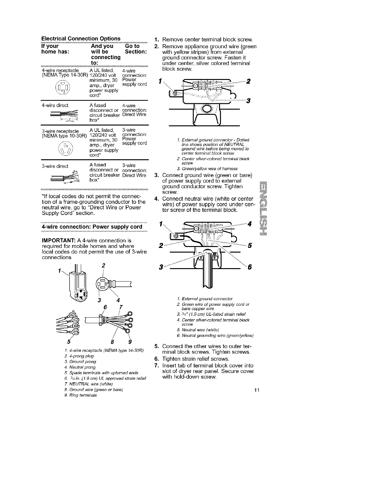
Electrical Connection Options
If your And you Go to
home has: will be Section:
connecting
to:
4-wire receptacle A UL listed, 4-wire
(NEMAType 14-30R)120/240volt connection:
minimum, 30 Power
amp.,dryer supply cord
powersupply
cord*
4-wire direct A fused 4-wire
disconnect or connection:
circuit breaker Direct Wire
box*
3-wire receptacle A UL listed, 3-wire
(NEMAtype 10-30R) 120/240 volt connection:
minimum, 30 Power
amp., dryer supply cord
power supply
cord*
3-wire direct 3-wire
connection:
Direct Wire
A fused
disconnect or
circuit breaker
box*
*If local codes do not permit the connec-
tion of a frame-grounding conductor to the
neutral wire, go to "Direct Wire or Power
Supply Cord" section.
4-wire connection: Power supply cord
IMPORTANT: A 4-wire connection is
required for mobile homes and where
local codes do not permit the use of 3-wire
connections
2
3 4
67
5 8 9
1. 4-wire receptacle (NEMA type 14-30R)
2. 4-prong plug
3. Ground prong
4. Neutral prong
5. Spade terminals with upturned ends
6. 3/4in. ( 1.9 cm) UL approved strain relief
7. NEUTRAL wire (white)
8. Ground wire (green or bare)
9. Ring terminals
1. Remove center terminal block screw.
2. Remove appliance ground wire (green
with yellow stripes) from external
ground connector screw. Fasten it
under center, silver colored terminal
block screw.
1\
3
1. External ground connector -Dotted
line shows position of NEUTRAL
ground wire before being moved to
center terminal block screw
2 Center silver-colored terminal block
SCreW
&Green/yellow wire of harness
3. Connect ground wire (green or bare)
of power supply cord to external
ground conductor screw. Tighten
screw.
4. Connect neutral wire (white or center
wire) of power supply cord under cen-
ter screw of the terminal block.
, ..................4_
1. External ground connector
2 Green wire of power supply cord or
bare copper wire
& 3/4"(1.9 cm) ULdisted strain relief
4 Center silver-colored terminal block
screw
5. Neutral wire (white)
6. Neutral grounding wire (green/yellow)
5. Connect the other wires to outer ter-
minal block screws, Tighten screws.
6. Tighten strain relief screws.
7. Insert tab of terminal block cover into
slot of dryer rear panel. Secure cover
with hold-down screw.
11
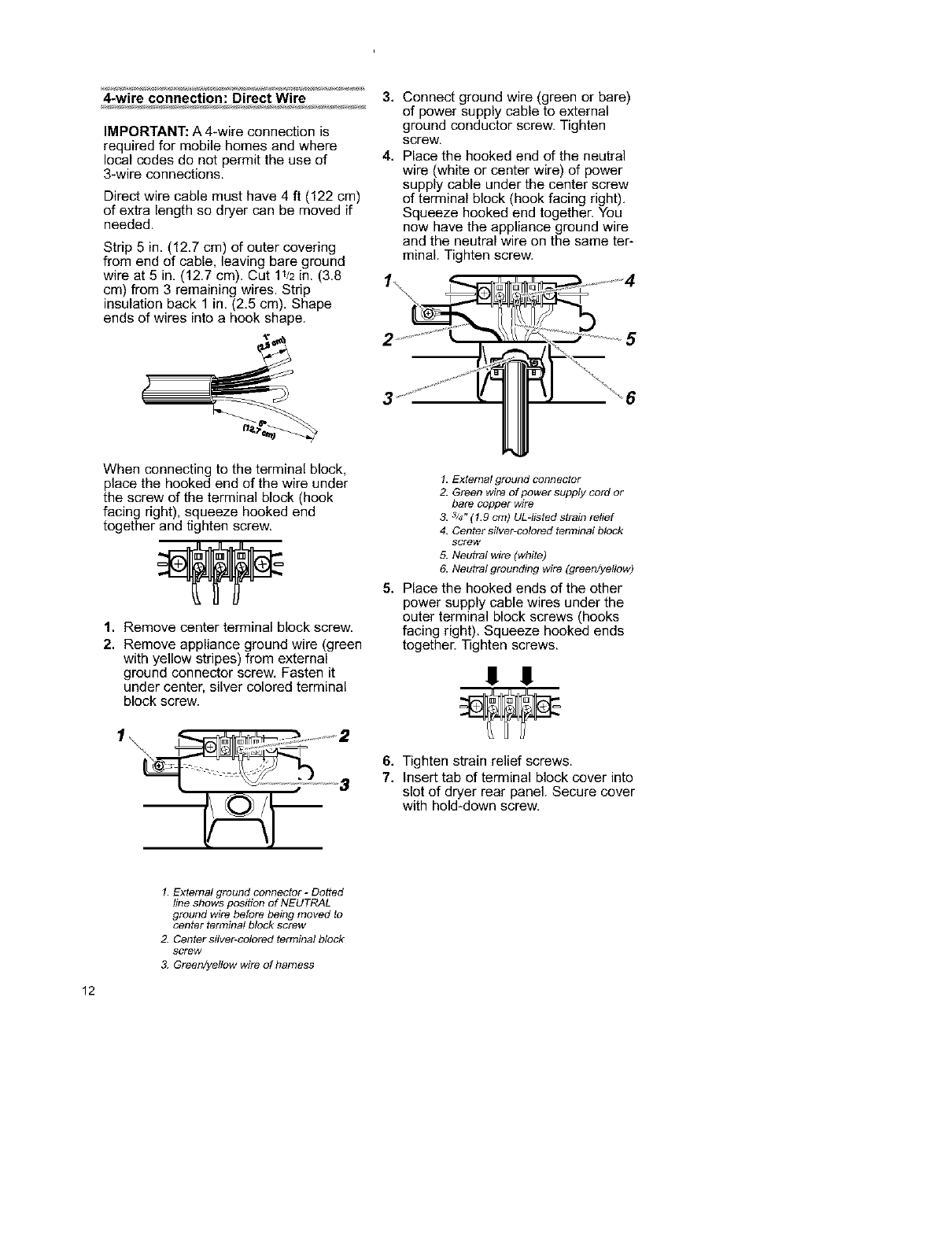
4-wire connection: Direct Wire
IMPORTANT: A 4-wire connection is
required for mobile homes and where
local codes do not permit the use of
3-wire connections.
Direct wire cable must have 4 ft (122 cm)
of extra length so dryer can be moved if
needed.
Strip 5 in. (12.7 cm) of outer covering
from end of cable, leaving bare ground
wire at 5 in, (12.7 cm). Cut 11_2in. (3.8
cm) from 3 remaining wires. Strip
insulation back 1 in, (2,5 cm), Shape
ends of wires into a hook shape.
3,
4,
Connect ground wire (green or bare)
of power supply cable to external
ground conductor screw. Tighten
screw,
Place the hooked end of the neutral
wire (white or center wire) of power
supply cable under the center screw
of terminal block (hook facing right),
Squeeze hooked end together. You
now have the appliance ground wire
and the neutral wire on the same ter-
minal. Tighten screw.
25
When connecting to the terminal block,
place the hooked end of the wire under
the screw of the terminal block (hook
facing right), squeeze hooked end
together and tighten screw.
1. Remove center terminal block screw.
2. Remove appliance ground wire (green
with yellow stripes) from external
ground connector screw, Fasten it
under center, silver colored terminal
block screw.
I. External ground connector
2. Green wire of power supply cord or
bare copper wire
3. 3/4" (1.9 cm) UL-listed strain relief
4. Center silver-colored terminal block
sGrew
5. Neuh_l wire (white)
6. Neuh_l grounding wire (green/yellow)
5, Place the hooked ends of the other
power supply cable wires under the
outer terminal block screws (hooks
facing right). Squeeze hooked ends
together. Tighten screws.
11 11
_3
6. Tighten strain relief screws.
7, Insert tab of terminal block cover into
slot of dryer rear panel. Secure cover
with hold-down screw.
12
1External ground connector -Dotted
line shows position of NEUTRAL
ground wire before being moved to
center terminal block screw
2. Center silver-colored terminal block
screw
&Green/yellow wire of harness
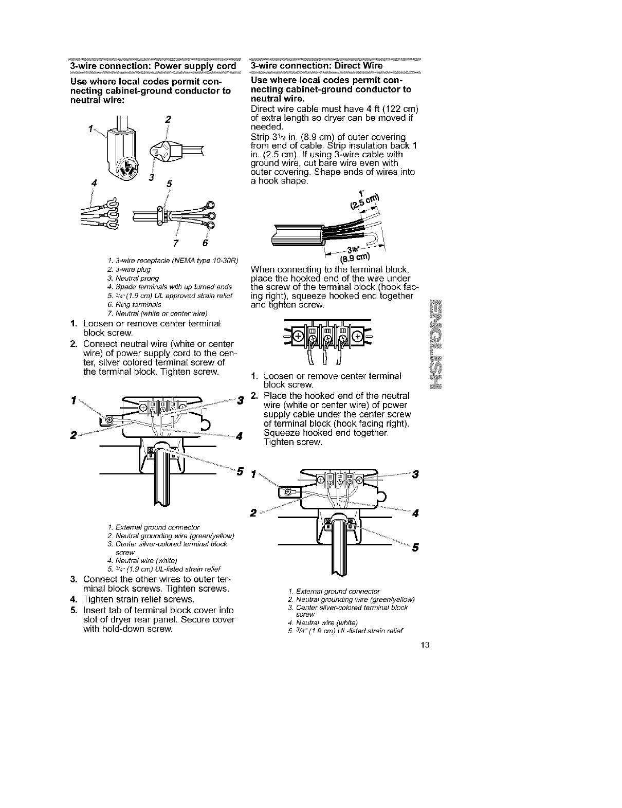
3-wire connection: Power supply cord
Use where local codes permit con-
necting cabinet-ground conductor to
neutral wire:
2
3
45
7 6
1. 3-wire receptacle (NEMA type 10-30R)
2. 3-wire plug
3. Neutral prong
4. Spade terminals with up turned ends
5. 3/4"(1.9 cm) UL approved strain relief
6. Ring terminals
7. Neutral (white or center wire)
1, Loosen or remove center terminal
block screw.
2, Connect neutral wire (white or center
wire) of power supply cord to the cen-
ter, silver colored terminal screw of
the terminal block, Tighten screw.
3-wire connection: Direct Wire
Use where local codes permit con-
necting cabinet-ground conductor to
neutral wire.
Direct wire cable must have 4 ft (122 cm)
of extra length so dryer can be moved if
needed.
Strip 31J2in. (8.9 cm) of outer covering
from end of cable. Strip insulation back 1
in. (2.5 cm), If using 3-wire cable with
ground wire, cut bare wire even with
outer covering. Shape ends of wires into
ahook shape.
,g cm_
When connecting to the terminal block,
place the hooked end of the wire under
the screw of the terminal block (hook fac-
ing right), squeeze hooked end together
and tighten screw.
1, Loosen or remove center terminal
block screw,
2. Place the hooked end of the neutral
wire (white or center wire) of power
supply cable under the center screw
of terminal block (hook facing right).
Squeeze hooked end together.
Tighten screw.
1. External ground connector
2. Neutral grounding wire (green/yellow)
3. Center silver-colored terminal block
sGrew
4. Neutral wire (white)
5. 3/4"(1.9 cm) ULdisted strain relief
3, Connect the other wires to outer ter-
minal block screws. Tighten screws.
4. Tighten strain relief screws.
5, Insert tab of terminal block cover into
slot of dryer rear panel. Secure cover
with hold-down screw.
2
1. External ground connector
2. Neutral grounding wire (green/yellow)
3. Center silver-colored terminal block
screw
4. Neutral wire (white)
5. 3/4" (1.9 cm) UL-listed strain relief
13
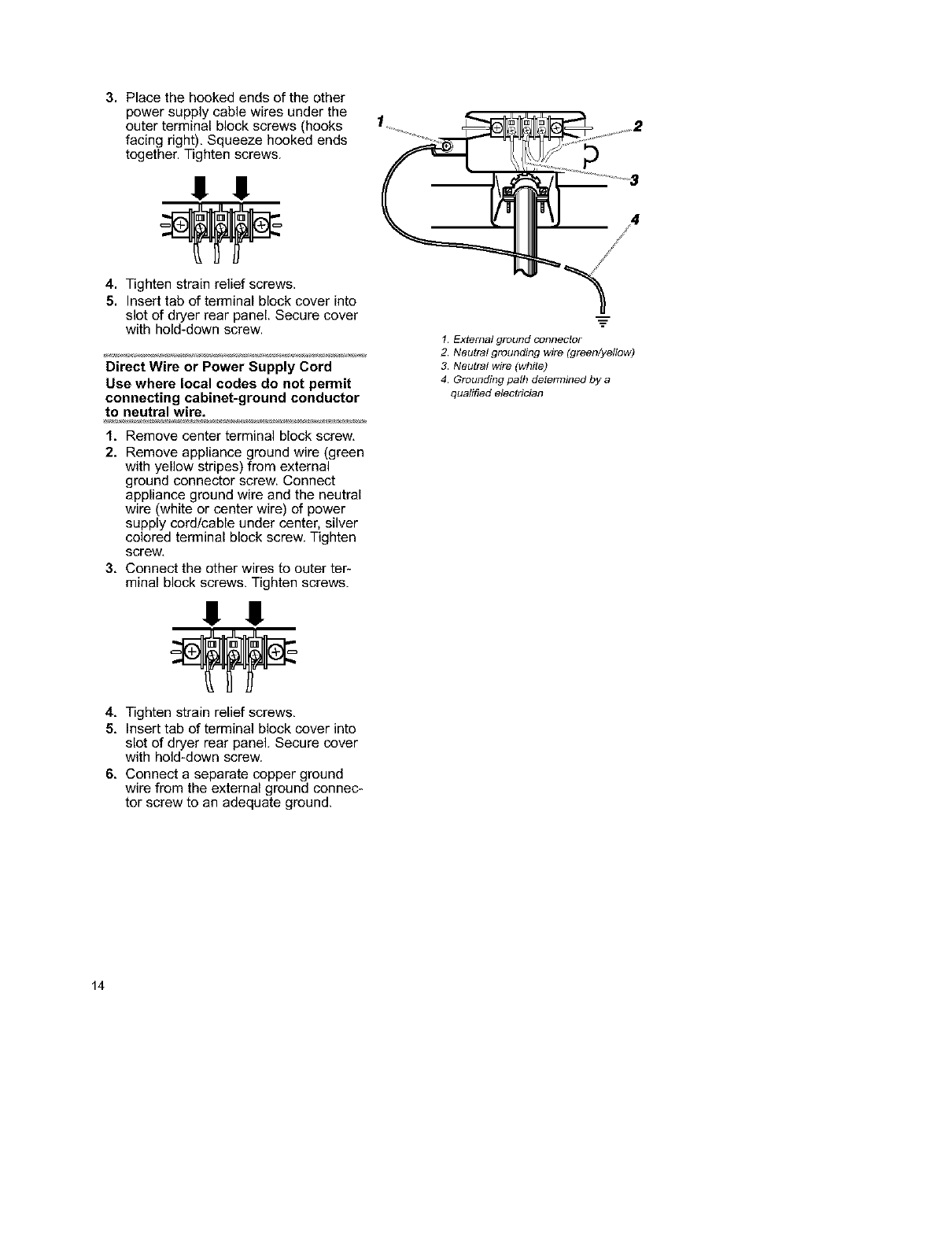
3. Place the hooked ends of the other
power supply cable wires under the
outer terminal block screws (hooks
facing right), Squeeze hooked ends
together. Tighten screws.
1!!!
4. Tighten strain relief screws.
5. Insert tab of terminal block cover into
slot of dryer rear panel. Secure cover
with hold-down screw.
Direct Wire or Power Supply Cord
Use where local codes do not permit
connecting cabinet-ground conductor
to neutral wire.
1, Remove center terminal block screw,
2. Remove appliance ground wire (green
with yellow stripes) from external
ground connector screw. Connect
appliance ground wire and the neutral
wire (white or center wire) of power
supply cord/cable under center, silver
colored terminal block screw. Tighten
screw,
3, Connect the other wires to outer ter-
minal block screws. Tighten screws.
!!!!
4, Tighten strain relief screws,
5, Insert tab of terminal block cover into
slot of dryer rear panel. Secure cover
with hold-down screw.
6, Connect a separate copper ground
wire from the external ground connec-
tor screw to an adequate ground.
/
/
1. External ground connector
2. Neutral grounding wire (green/yellow)
3. Neutral wire (white)
4. Grounding pafi7 determined by a
qualified electrician
14
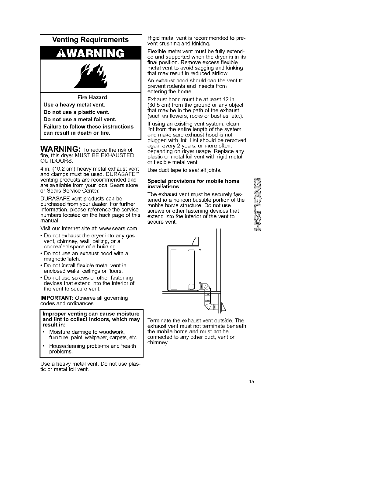
Venting Requirements
Fire Hazard
Use aheavy metal vent.
Do not use a plastic vent.
Do not use a metal foil vent.
Failure to follow these instructions
can result in death or fire.
WARNING: To reduce the risk of
fire, this dryer MUST BE EXHAUSTED
OUTDOORS.
4 in. (10.2 cm) heavy metal exhaust vent
and clamps must be used. DURASAFE TM
venting products are recommended and
are available from your local Sears store
or Sears Service Center.
DURASAFE vent products can be
purchased from your dealer. For further
information, please reference the service
numbers located on the back page of this
manual.
Visit our Internet site at: www.sears.com
• Do not exhaust the dryer into any gas
vent, chimney, wall, ceiling, or a
concealed space of a building.
• Do not use an exhaust hood with a
magnetic latch.
• Do not install flexible metal vent in
enclosed walls, ceilings or floors.
• Do not use screws or other fastening
devices that extend into the interior of
the vent to secure vent.
IMPORTANT: Observe all governing
codes and ordinances.
Improper venting can cause moisture
and lint to collect indoors, which may
result in:
• Moisture damage to woodwork,
furniture, paint, wallpaper, carpets, etc.
• Housecleaning problems and health
problems.
Rigid metal vent is recommended to pre-
vent crushing and kinking.
Flexible metal vent must be fully extend-
ed and supported when the dryer is in its
final position. Remove excess flexible
metal vent to avoid sagging and kinking
that may result in reduced airflow.
An exhaust hood should cap the vent to
prevent rodents and insects from
entering the home.
Exhaust hood must be at least 12 in.
(30.5 cm) from the ground or any object
that may be in the path of the exhaust
(such as flowers, rocks or bushes, etc.).
If using an existing vent system, clean
lint from the entire length of the system
and make sure exhaust hood is not
plugged with lint. Lint should be removed
again every 2 years, or more often,
depending on dryer usage. Replace any
plastic or metal foil vent with rigid metal
or flexible metal vent.
Use duct tape to seal all joints.
Special provisions for mobile home
installations
The exhaust vent must be securely fas-
tened to a noncombustible portion of the
mobile home structure. Do not use
screws or other fastening devices that
extend into the interior of the vent to
secure vent.
Terminate the exhaust vent outside. The
exhaust vent must not terminate beneath
the mobile home and must not be
connected to any other duct, vent or
chimney.
Use a heavy metal vent. Do not use plas-
tic or metal foil vent.
15
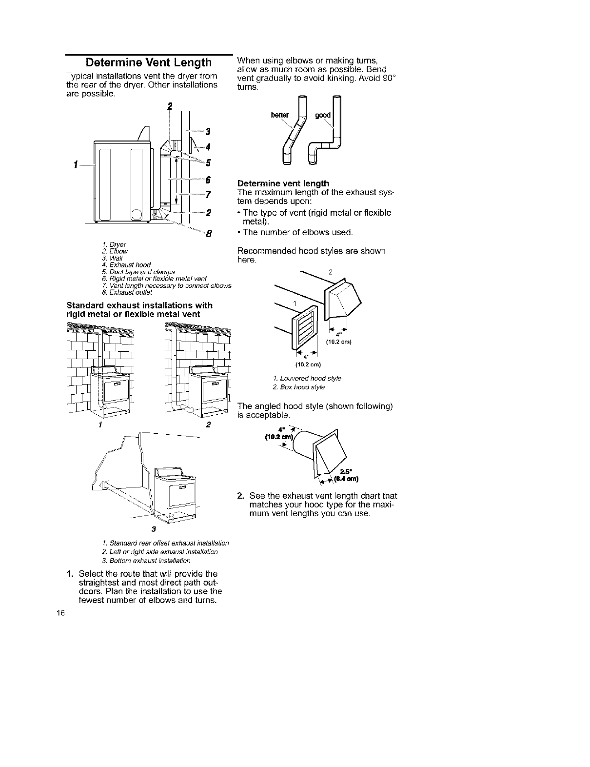
Determine Vent Length
Typical installations vent the dryer from
the rear of the dryer. Other installations
are possible.
2
!
I
1. Dryer
2Elbow
3. Wall
4. Exhaust hood
5. Duct tape and clamps
When using elbows or making turns,
allow as much room as possible, Bend
vent gradually to avoid kinking. Avoid 90 °
turns.
Determine vent length
The maximum length of the exhaust sys_
tem depends upon:
• The type of vent (rigid metal or flexible
metal).
• The number of elbows used.
Recommended hood styles are shown
here.
6. Rigid metal or flexible metal vent _ _
7. Vent length necessary to connect elbows
8. Exhaust outlet
Standard exhaust installations with 1
rigid metal or flexible metal vent
1. Louvered hood style
2. Box hood style
The angled hood style (shown following)
is acceptable.
1 2
2. See the exhaust vent length chart that
matches your hood type for the maxi-
mum vent lengths you can use.
3
1. Standard rear offset exhaust instaflation
2Left or right side exhaust installation
3. Bottom exhaust installation
1. Select the route that will provide the
straightest and most direct path out-
doors, Plan the installation to use the
fewest number of elbows and turns.
16
Do not use vent runs longer than those
specified in Vent Length Chart.
Exhaust systems longer than those speci-
fied will:
• Shorten the life of the dryer.
• Reduce performance, resulting in longer
drying times and increased energy
usage.
3, Determine the number of elbows you
will need.
in the column listing the type of metal
vent you are using (rigid metal or flex-
ible metal), find the maximum length
of metal vent on the same line as the
number of elbows.
Vent Length Chart
Number of Type of Boxor Angled
90° turns vent Louvered hoods
or elbows hoods
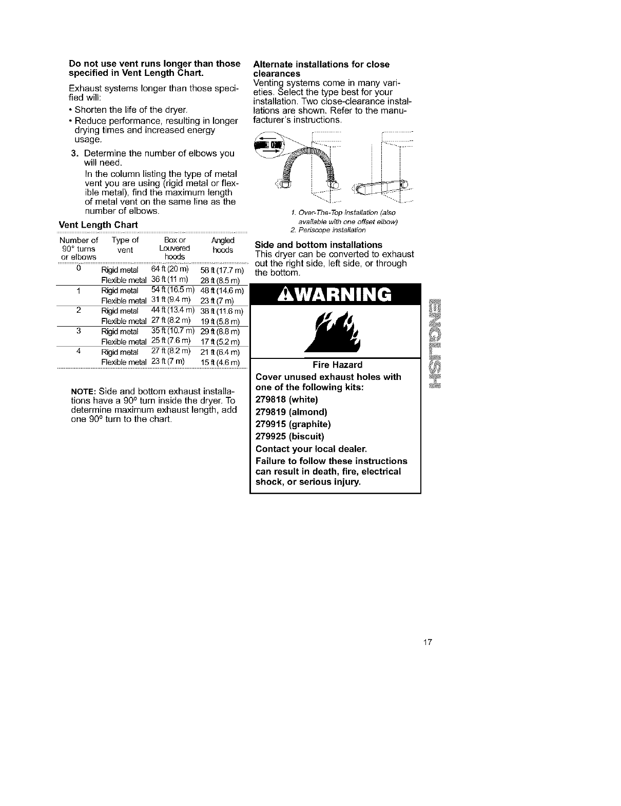
Alternate installations for close
clearances
Venting systems come in many vari-
eties. Select the type best for your
installation. Two close-clearance instal-
lations are shown. Refer to the manu*
facturer's instructions.
1. Over-The-Top installation (also
available with one offset elbow)
2. Periscope installation
Side and bottom installations
This dryer can be converted to exhaust
.............................................................................................................................................................................................................................................out the right side, left side, or through
0 Rigidmetal 64ft (20m) 58It(17.7m) the bottom.
Flexiblemetal 36ft (11m) 28ft
1 Rigidmetal 54ft (16.5m) 48 It(14.6m)
Flexiblemetal 31ft (9.4m) 23 It(7 m)
2 Rigidmetal 44ft (13.4m) 38 It(11.6m)
Flexiblemetal 27ft(8.2m) 19ft(5.8m)
3 Rigidmetal 35ft (10.7m) 29 _(8.8m)
Flexiblemetal 25ft (7.6m) 17 It(5.2m)
4 Rigidmetal 27ft (8.2m) 21ff(6.4 m)
Flexiblemetal 23ft (7m) 15ft(4.6m)
NOTE: Side and bottom exhaust installa-
tions have a 90° turn inside the dryer, To
determine maximum exhaust length, add
one 90 ° turn to the chart.
Fire Hazard
Cover unused exhaust holes with
one of the following kits:
279818 (white)
279819 (almond)
279915 (graphite)
279925 (biscuit)
Contact your local dealer.
Failure to follow these instructions
can result in death, fire, electrical
shock, or serious injury.
17
Install Vent System
1. (Optional) Put on safety glasses and
gloves.
2, Install exhaust hood. Use caulking
compound to seal exterior wall open_
ing around exhaust hood.
3. Connect vent to exhaust hood. Vent
must fit inside exhaust hood. Secure
vent to exhaust hood with 4 in.
(10.2 cm) clamp.
4. Run vent to dryer location. Use the
straightest path possible. See
"Determine Vent Length." Avoid 90°
turns. Use duct tape to seal all joints.
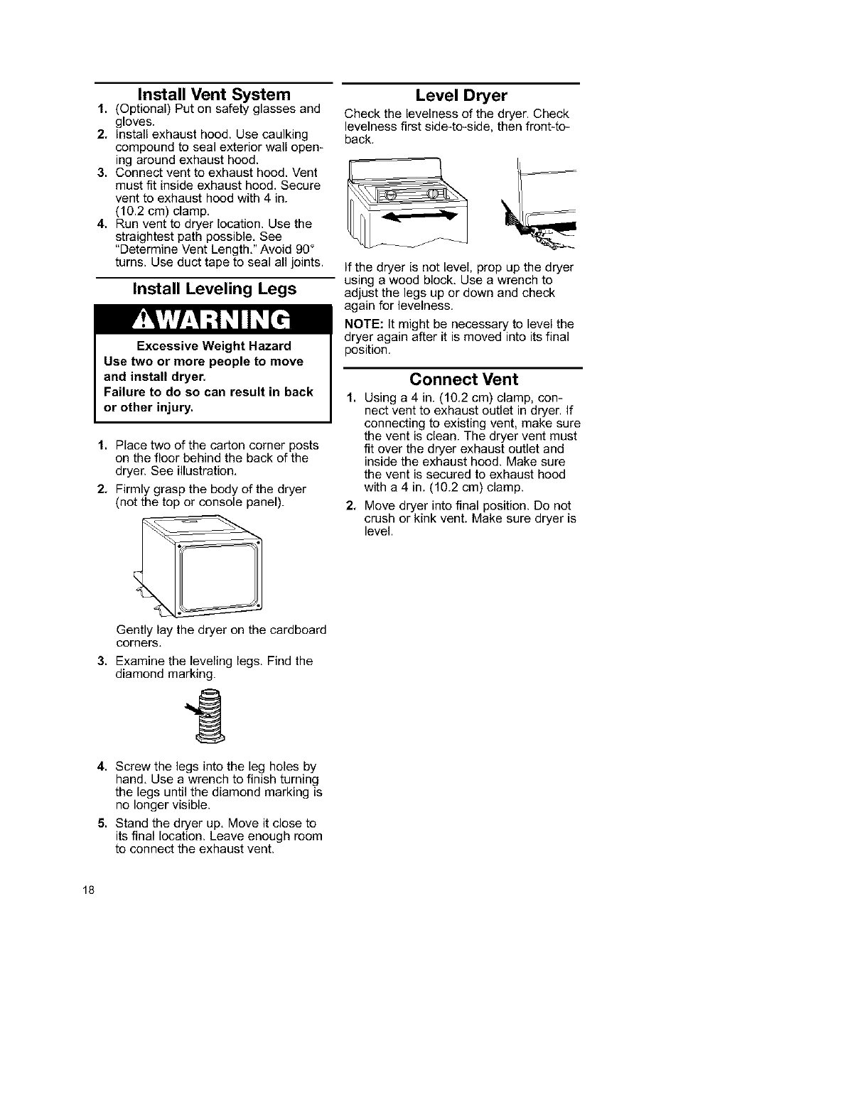
Install Leveling Legs
Excessive Weight Hazard
Use two or more people to move
and install dryer.
Failure to do so can result in back
or other injury.
1. Place two of the carton corner posts
on the floor behind the back of the
dryer. See illustration,
2, Firmly grasp the body of the dryer
(not the top or console panel).
Level Dryer
Check the levelness of the dryer. Check
levelness first side-to-side, then front-to-
back.
If the dryer is not level, prop up the dryer
using a wood block, Use a wrench to
adjust the legs up or down and check
again for levelness.
NOTE: It might be necessary to level the
dryer again after it is moved into its final
position.
Connect Vent
1. Using a 4 in. (10.2 cm) clamp, con-
nect vent to exhaust outlet in dryer. If
connecting to existing vent, make sure
the vent is clean. The dryer vent must
fit over the dryer exhaust outlet and
inside the exhaust hood. Make sure
the vent is secured to exhaust hood
with a 4 in. (10.2 cm) clamp.
2, Move dryer into final position. Do not
crush or kink vent. Make sure dryer is
level.
Gently lay the dryer on the cardboard
corners,
3. Examine the leveling legs. Find the
diamond marking.
1
4. Screw the legs into the leg holes by
hand, Use a wrench to finish turning
the legs until the diamond marking is
no longer visible.
5. Stand the dryer up. Move it close to
its final location. Leave enough room
to connect the exhaust vent.
18
Complete Installation
1, Check to be sure all parts are now
installed. If there is an extra part, go
back through the steps to see which
step was skipped.
2. Check to be sure you have all of
your tools.
3. Dispose of all packaging materials.
4. Check the dryer's final location. Be
sure the vent is not crushed or
kinked.
5, Check to be sure the dryer is level.
(See "Level Dryer.")
6, Plug into a grounded outlet. Turn
power on,
7, Remove the blue protective film on
the console and any tape remaining
on the dryer.
8. Read "Operating Your Dryer."
9, Wipe the dryer drum interior
thoroughly with a damp cloth to
remove any dust,
10. Set the dryer on a full heat cycle (not
the Air cycle) for 20 minutes, Open
the dryer door after five minutes and
feel for heat, If you do not feel heat,
turn the dryer off and wait five
minutes.
Then check the following:
•Controls are set in a running or "On"
position.
• Start button has been pushed firmly.
Repeat 5-minute test as outlined above.
If dryer still does not operate properly,
check the following:
• Dryer is plugged into a grounded outlet.
• Electrical supply is connected.
• House fuse is intact and tight; or circuit
breaker has not tripped.
• Dryer door is closed.
• If dryer makes an unusual noise, check
that dryer is level.
• You may notice a burning odor. This
odor is common when the heating
element is first used. The odor will go
away.
19
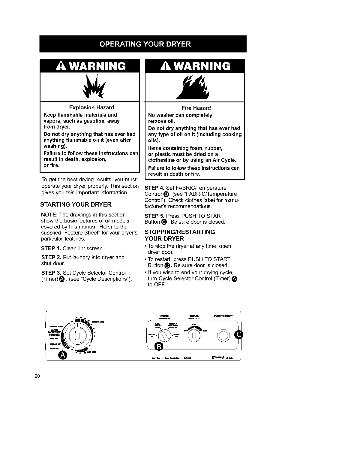
Explosion Hazard
Keep flammable materials and
vapors, such as gasoline, away
from dryer.
Do not dry anything that has ever had
anything flammable on it (even after
washing).
Failure to follow these instructions can
result in death, explosion,
or fire.
To get the best drying results, you must
operate your dryer properly. This section
gives you this important information.
STARTING YOUR DRYER
NOTE: The drawings in this section
show the basic features of all models
covered by this manual. Refer to the
supplied "Feature Sheet" for your dryer's
particular features.
STEP 1. Clean lint screen.
STEP 2. Put laundry into dryer and
shut door.
STEP 3. Set Cycle Selector Control
(Timer)_, (see "Cycle Descriptions").
Fire Hazard
No washer can completely
remove oil.
Do not dry anything that has ever had
any type of oil on it (including cooking
oils).
Items containing foam, rubber,
or plastic must be dried on a
clothesline or by using an Air Cycle.
Failure to follow these instructions can
result in death or fire.
STEP 4. Set FABRiC/Temperature
Control @, (see "FABRiC/Temperature
Control"), Check clothes label for manu-
facturer's recommendations.
STEP 5. Press PUSH TO START
Button _. Be sure door is closed.
STOPPING/RESTARTING
YOUR DRYER
•To stop the dryer at any time, open
dryer door.
•To restart, press PUSH TO START
Button _. Be sure door is closed.
• If you wish to end your drying cycle,
turn Cycle Selector Control (Timer)
to OFR
ui_us411_ IITJ._lr
20
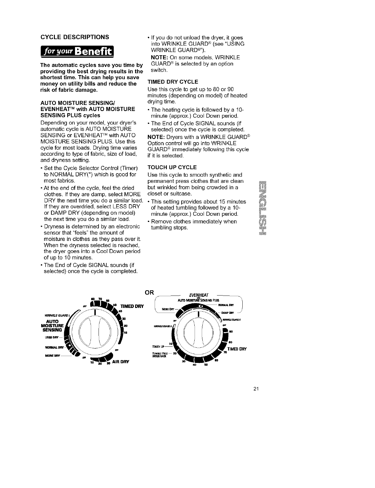
CYCLE DESCRIPTIONS
The automatic cycles save you time by
providing the best drying results in the
shortest time. This can help you save
money on utility bills and reduce the
risk of fabric damage.
AUTO MOISTURE SENSING/
EVENHEAT TM with AUTO MOISTURE
SENSING PLUS cycles
Depending on your model, your dryer's
automatic cycle is AUTO MOISTURE
SENSING or EVENHEAT TM with AUTO
MOISTURE SENSING PLUS. Use this
cycle for most loads. Drying time varies
according to type of fabric, size of load,
and dryness setting.
• Set the Cycle Selector Control (Timer)
to NORMAL DRY(*) which is good for
most fabrics.
• At the end of the cycle, feel the dried
clothes. If they are damp, select MORE
DRY the next time you do a similar load.
If they are overdried, select LESS DRY
or DAMP DRY (depending on model)
the next time you do a similar load.
• Dryness is determined by an electronic
sensor that "feels" the amount of
moisture in clothes as they pass over it.
When the dryness selected is reached,
the dryer goes into a Cool Down period
of up to 10 minutes.
• The End of Cycle SIGNAL sounds (if
selected) once the cycle is completed.
•If you do not unload the dryer, it goes
into WRINKLE GUARD ®(see "USING
WRINKLE GUARD®").
NOTE: On some models, WRINKLE
GUARD ®is selected by an option
switch.
TIMED DRY CYCLE
Use this cycle to get up to 80 or 90
minutes (depending on model) of heated
drying time.
• The heating cycle is followed by a 10-
minute (approx.) Cool Down period.
• The End of Cycle SIGNAL sounds (if
selected) once the cycle is completed.
NOTE: Dryers with aWRINKLE GUARD ®
Option control will go into WRINKLE
GUARD ®immediately following this cycle
if it is selected.
TOUCH UP CYCLE
Use this cycle to smooth synthetic and
permanent press clothes that are clean
but wrinkled from being crowded in a
closet or suitcase.
• This setting provides about 15 minutes
of heated tumbling followed by a 10-
minute (approx.) Cool Down period.
•Remove clothes immediately when
tumbling stops.
AUTO
MOIS'IIJRE
SENSING
LES$ DRY
OR
"RMED DRY
TIMED DRY
40 SO
21
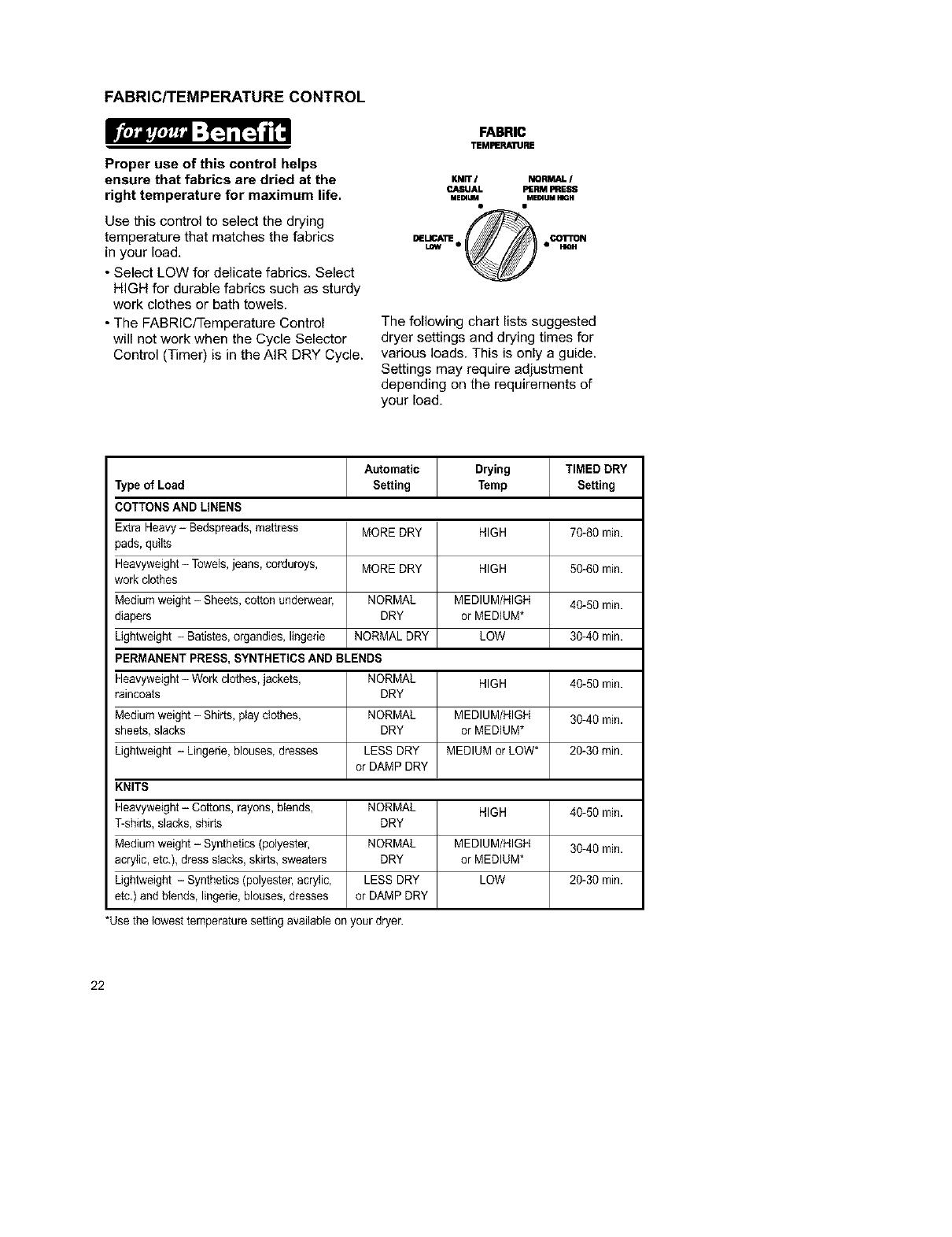
FABRIC/TEMPERATURE CONTROL
Proper use of this control helps
ensure that fabrics are dried at the
right temperature for maximum life.
Use this control to select the drying
temperature that matches the fabrics
in your load.
• Select LOW for delicate fabrics. Select
HIGH for durable fabrics such as sturdy
work clothes or bath towels.
• The FABRiC/Temperature Control
will not work when the Cycle Selector
Control (Timer) is in the AIR DRY Cycle.
FABRIC
TEMFERAIURE
KNiT INORMAL /
P..JLSUAL PERM PRESS
MEmLIM MEmUM HIGH
DELICA_ _• • CO1"rON
LOW e_ •HIG H
The following chart lists suggested
dryer settings and drying times for
various loads. This is only a guide.
Settings may require adjustment
depending on the requirements of
your load.
Automatic Drying TIMED DRY
Type of Load Setting Temp Setting
COTTONS AND LINENS
Extra Heavy- Bedspreads, mattress MORE DRY HIGH 70-80 min.
pads, quilts
Heavyweight -Towels, jeans, corduroys, MORE DRY HIGH 50-60 min.
work clothes
Medium weight -Sheets, cotton underwear, NORMAL MEDIUM/HIGH 40-50 min.
diapers DRY or MEDIUM*
Lightweight - Batistes, organdies, lingerie NORMAL DRY LOW 30-40 min.
PERMANENT PRESS, SYNTHETICS AND BLENDS
Heavyweight -Work clothes, jackets, NORMAL HIGH 40-50 min.
raincoats DRY
Medium weight -Shirts, play clothes, NORMAL MEDIUM/HIGH 30-40 min.
sheets, slacks DRY or MEDIUM*
Lightweight - Lingerie, blouses, dresses LESS DRY MEDIUM or LOW* 20-30 rain.
or DAMP DRY
KNITS
Heavyweight- Cottons, rayons, blends, NORMAL HIGH 40-50 min.
T-shirts, slacks, shirts DRY
Medium weight - Synthetics (polyester, NORMAL MEDIUM/HIGH 30-40 min.
acrylic, etc.), dress slacks, skirts, sweaters DRY or MEDIUM*
Lightweight - Synthetics (polyester, acrylic, LESS DRY LOW 20-30 min.
etc.) and blends, lingerie, blouses, dresses or DAMP DRY
*Use the lowest temperature setting available on your dryer.
22
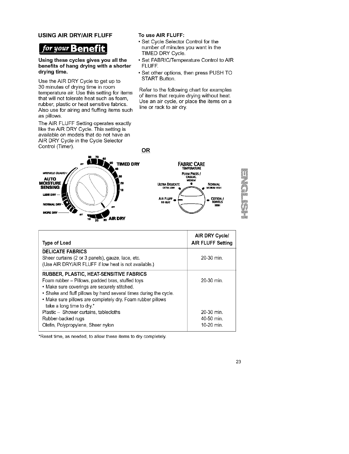
USING AIR DRY/AIR FLUFF
Using these cycles gives you all the
benefits of hang drying with ashorter
drying time,
Use the AIR DRY Cycle to get up to
30 minutes of drying time in room
temperature air, Use this setting for items
that will not tolerate heat such as foam,
rubber, plastic or heat sensitive fabrics,
Also use for airing and fluffing items such
as pillows.
The AIR FLUFF Setting operates exactly
like the AIR DRY Cycle. This setting is
available on models that do not have an
AIR DRY Cycle in the Cycle Selector
Control (Timer).
To use AIR FLUFF:
• Set Cycle Selector Control for the
number of minutes you want in the
TIMED DRY Cycle.
• Set FABRIC/Temperature Control to AIR
FLUFR
• Set other options, then press PUSH TO
START Button.
Refer to the following chart for examples
of items that require drying without heat.
Use an air cycle, or place the items on a
line or rack to air dry.
OR
TIMED DRY FABRICCARE
_MFERA11JRE
W_Nr._GUA_D, PERMPRISS/
_A3UAL
AUTO .EDU.
MOISTURE ULnA DELICA1_ • NORMAL
SENSING
_LOW • • ME_JMHI_
LESS DRY !10
AIR FLUFFe e* ODIION I
NOH_T TOWELq
AIR DRY Cycle/
Type of Load AIR FLUFF Setting
DELICATE FABRICS
Sheer curtains (2 or 3 panels), gauze, lace, etc. 20-30 min.
(Use AIR DRY/AIR FLUFF if low heat is not available.)
20-30 min.
RUBBER, PLASTIC, HEAT-SENSITIVE FABRICS
Foam rubber - Pillows, padded bras, stuffed toys
• Make sure coverings are securely stitched.
• Shake and fluff pillows by hand several times during the cycle.
• Make sure pillows are completely dry. Foam rubber pillows
take alongtime to dry.*
Plastic - Shower curtains, tablecloths
Rubber-backed rugs
Olefin, Polypropylene, Sheer nylon
20-30 min.
40-50 min.
10-20 min.
*Reset time, as needed, to allow these items to dry completely.
23
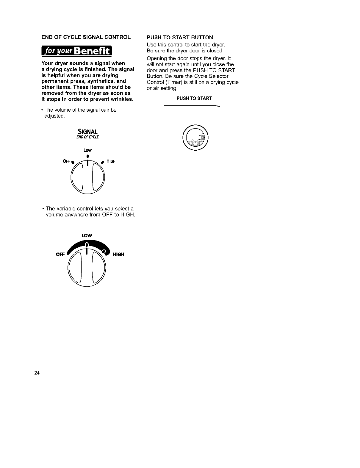
END OF CYCLE SIGNAL CONTROL
Your dryer sounds a signal when
a drying cycle is finished. The signal
is helpful when you are drying
permanent press, synthetics, and
other items. These items should be
removed from the dryer as soon as
it stops in order to prevent wrinkles.
• The volume of the signal can be
adjusted.
SIGNAL
ENDOFCYCLE
LOW
e
OFF_ HI6H
PUSH TO START BUTTON
Use this control to start the dryer.
Be sure the dryer door is closed.
Opening the door stops the dryer. It
will not start again until you close the
door and press the PUSH TO START
Button, Be sure the Cycle Selector
Control (Timer) is still on adrying cycle
or air setting.
PUSH TO START
©
• The variable control lets you select a
volume anywhere from OFF to HIGH.
LOW
HIGH
24
EVENHEAT TM with AUTO MOISTURE USING WRINKLE GUARD ®
SENSING PLUS
EVENHEAT TM with AUTO MOISTURE
SENSING PLUS is the only system
that uses 2 different sensors to
"understand" how fast a load is drying
and adjusts time for optimal fabric
care.
This cycle uses 2 moisture-sensing strips
in the back of the dryer. When strips no
longer "feel" any moisture in the clothes
the dryer automatically turns off to pre-
vent overdrying and shrinking.
COOL DOWN
Approximately ten minutes before the end
of the AUTO MOISTURE SENSING and
TIMED DRY Cycles, clothes are tumbled
without heat to help reduce wrinkles and
make clothes more comfortable to handle.
WRINKLE GUARD ®helps keep your
permanent press items wrinkle free
when you don't unload the dryer
promptly at the end of the automatic
cycle.
If you do not open the door at the end
of the automatic cycle, WRINKLE
GUARD ®will tumble the clothes without
heat.
• On dryers with WRINKLE GUARD ® I,
the dryer will tumble the clothes
continuously for about 30 minutes
unless you open the dryer door.
• On dryers with WRINKLE GUARD ® II,
periodic tumbling every 15 seconds will
continue for about 40 minutes unless you
open the dryer doon
• On dryers with WRINKLE GUARD ® III,
periodic tumbling every 15 seconds will
continue for about 21_2hours unless you
open the dryer door.
• WRINKLE GUARD ® III has a
selectable ON/OFF Option. When
WRINKLE GUARD ®III is set at OFF, the
dryer stops after Cool Down and may be
unloaded.
The End of Cycle Signal will sound
after each period of tumbling, unless it
is off.
25
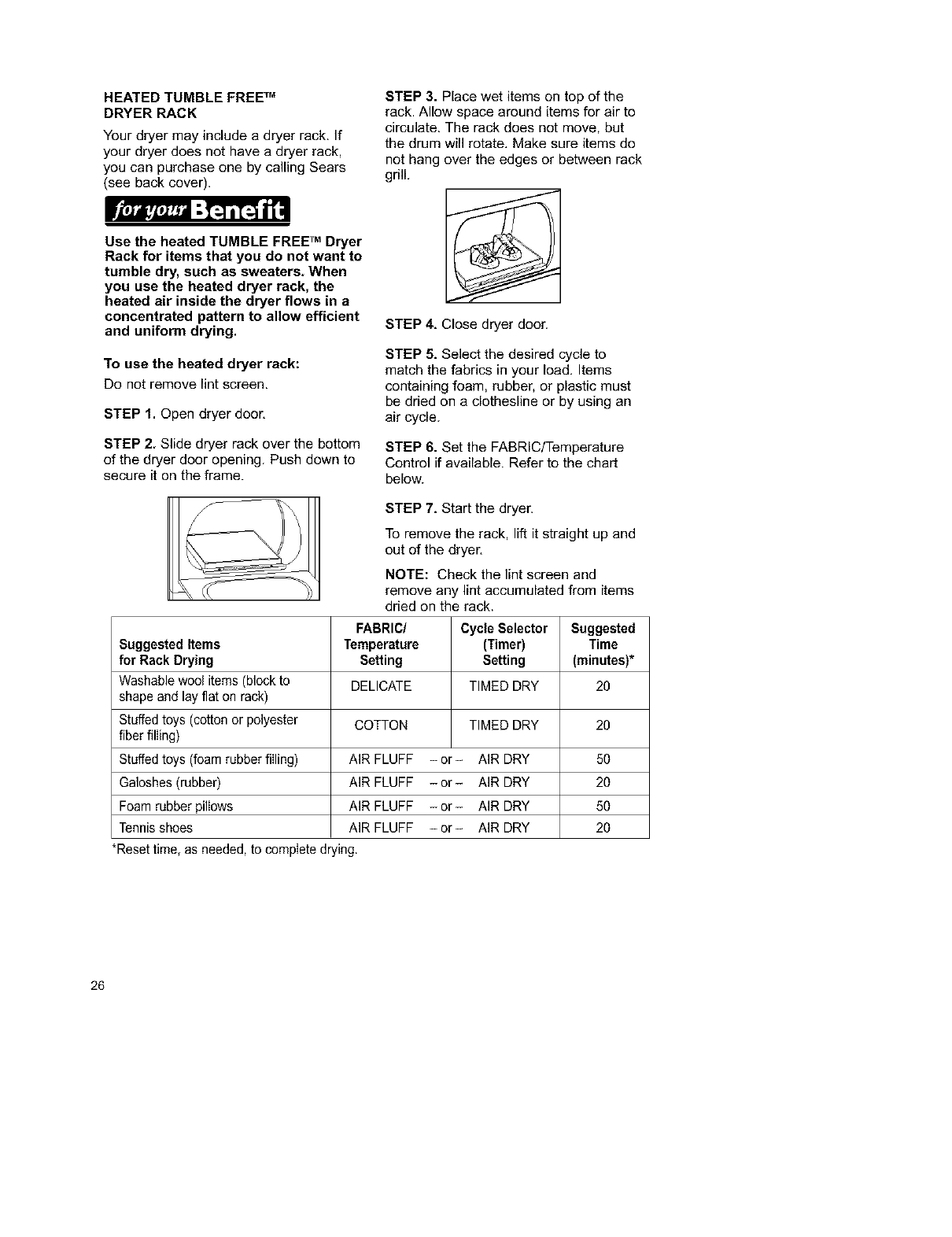
HEATED TUMBLE FREE TM
DRYER RACK
Your dryer may include a dryer rack. If
your dryer does not have a dryer rack,
you can purchase one by calling Sears
(see back cover).
Use the heated TUMBLE FREE TM Dryer
Rack for items that you do not want to
tumble dry, such as sweaters. When
you use the heated dryer rack, the
heated air inside the dryer flows in a
concentrated pattern to allow efficient
and uniform drying.
To use the heated dryer rack:
Do not remove lint screen.
STEP 1. Open dryer door.
STEP 2. Slide dryer rack over the bottom
of the dryer door opening. Push down to
secure it on the frame.
STEP 3. Place wet items on top of the
rack. Allow space around items for air to
circulate. The rack does net move, but
the drum will rotate. Make sure items do
not hang over the edges or between rack
grill.
STEP 4. Close dryer door.
STEP 5. Select the desired cycle to
match the fabrics in your load. Items
containing foam, rubber, or plastic must
be dried on a clothesline or by using an
air cycle.
STEP 6. Set the FABRIC/Temperature
Control if available. Refer to the chart
below.
STEP 7. Start the dryer.
To remove the rack, lift it straight up and
out of the dryer.
NOTE: Check the lint screen and
remove any lint accumulated from items
dried on the rack.
FABRIC/ Cycle Selector Suggested
Suggested Items Temperature (Timer) Time
for Rack Drying Setting Setting (minutes)*
Washable wool items (block to DELICATE TIMED DRY 20
shape and lay flat on rack)
Stuffed toys (cotton or polyester COTTON TIMED DRY 20
fiber filling)
Stuffed toys (foam rubber filling) AIR FLUFF - or- AIR DRY 50
Galoshes(rubber) AIR FLUFF -or- AIR DRY 20
Foam rubber pillows AIR FLUFF -or- AIR DRY 50
Tennis shoes AIR FLUFF -or- AIR DRY 20
*Reset time, as needed, to complete drying.
26
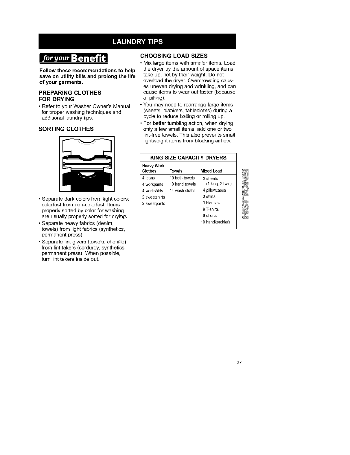
Follow these recommendations to help
save on utility bills and prolong the life
of your garments.
PREPARING CLOTHES
FOR DRYING
• Refer to your Washer Owner's Manual
for proper washing techniques and
additional laundry tips.
SORTING CLOTHES
CHOOSING LOAD SIZES
• Mix large items with smaller items. Load
the dryer by the amount of space items
take up, not by their weight. Do not
overload the dryer. Overcrowding caus-
es uneven drying and wrinkling, and can
cause items to wear out faster (because
of pilling).
• You may need to rearrange large items
(sheets, blankets, tablecloths) during a
cycle to reduce bailing or rolling up.
• For better tumbling action, when drying
only a few small items, add one or two
lint4ree towels. This also prevents small
lightweight items from blocking airflow.
• Separate dark colors from light colors;
colorfast from non-colorfast. Items
properly sorted by color for washing
are usually properly sorted for drying.
• Separate heavy fabrics (denim,
towels) from light fabrics (synthetics,
permanent press).
• Separate lint givers (towels, chenille)
from lint takers (corduroy, synthetics,
permanent press). When possible,
turn lint takers inside out.
KING SIZE CAPACITY DRYERS
Heavy Work
Clothes
4 jeans
4 workpants
4 workshirts
2 sweatshirts
2 sweatpants
Towels MixedLoad
10 bath towels 3 sheets
10 hand towels (1 king, 2 twin)
14 wash cloths 4 pillowcases
3 shirts
3 blouses
9 T-shirts
9 shorts
10 handkerchiefs
27
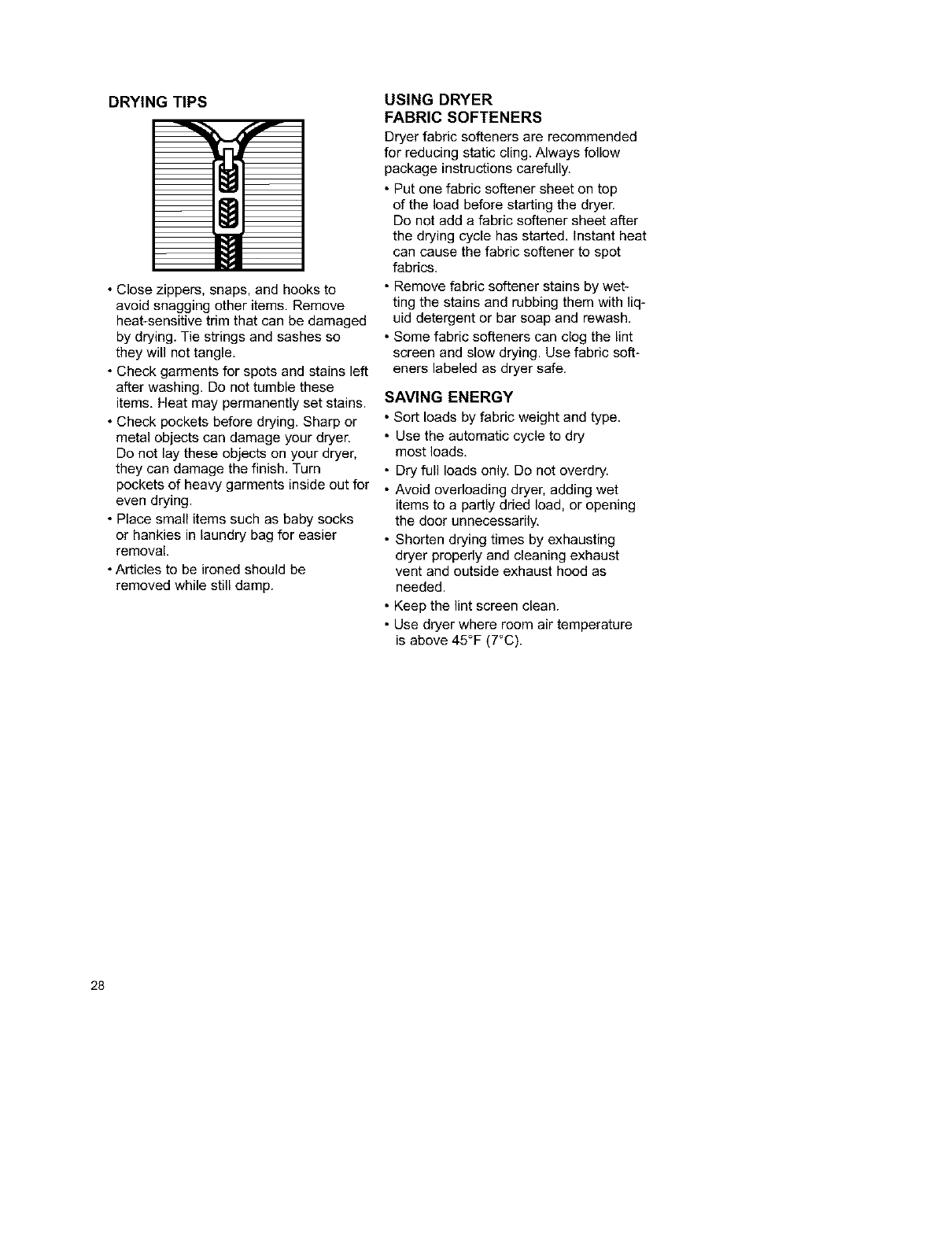
DRYING TIPS
• Close zippers, snaps, and hooks to
avoid snagging other items. Remove
heat-sensitive trim that can be damaged
by drying. Tie strings and sashes so
they will not tangle.
• Check garments for spots and stains left
after washing. Do not tumble these
items. Heat may permanently set stains.
• Check pockets before drying. Sharp or
metal objects can damage your dryer.
Do not lay these objects on your dryer,
they can damage the finish. Turn
pockets of heavy garments inside out for
even drying.
• Place small items such as baby socks
or hankies in laundry bag for easier
removal
• Articles to be ironed should be
removed while still damp.
USING DRYER
FABRIC SOFTENERS
Dryer fabric softeners are recommended
for reducing static cling. Always follow
package instructions carefully.
• Put one fabric softener sheet on top
of the load before starting the dryer.
Do not add a fabric softener sheet after
the drying cycle has started. Instant heat
can cause the fabric softener to spot
fabrics.
• Remove fabric softener stains by wet-
ting the stains and rubbing them with liq-
uid detergent or bar soap and rewash.
• Some fabric softeners can clog the lint
screen and slow drying. Use fabric soft-
eners labeled as dryer safe.
SAVING ENERGY
• Sort loads by fabric weight and type.
• Use the automatic cycle to dry
most loads.
• Dry full loads only. Do not overdry.
• Avoid overloading dryer, adding wet
items to a partly dried load, or opening
the door unnecessarily.
• Shorten drying times by exhausting
dryer properly and cleaning exhaust
vent and outside exhaust hood as
needed.
• Keep the lint screen clean.
• Use dryer where room air temperature
is above 45°F (7°C).
28
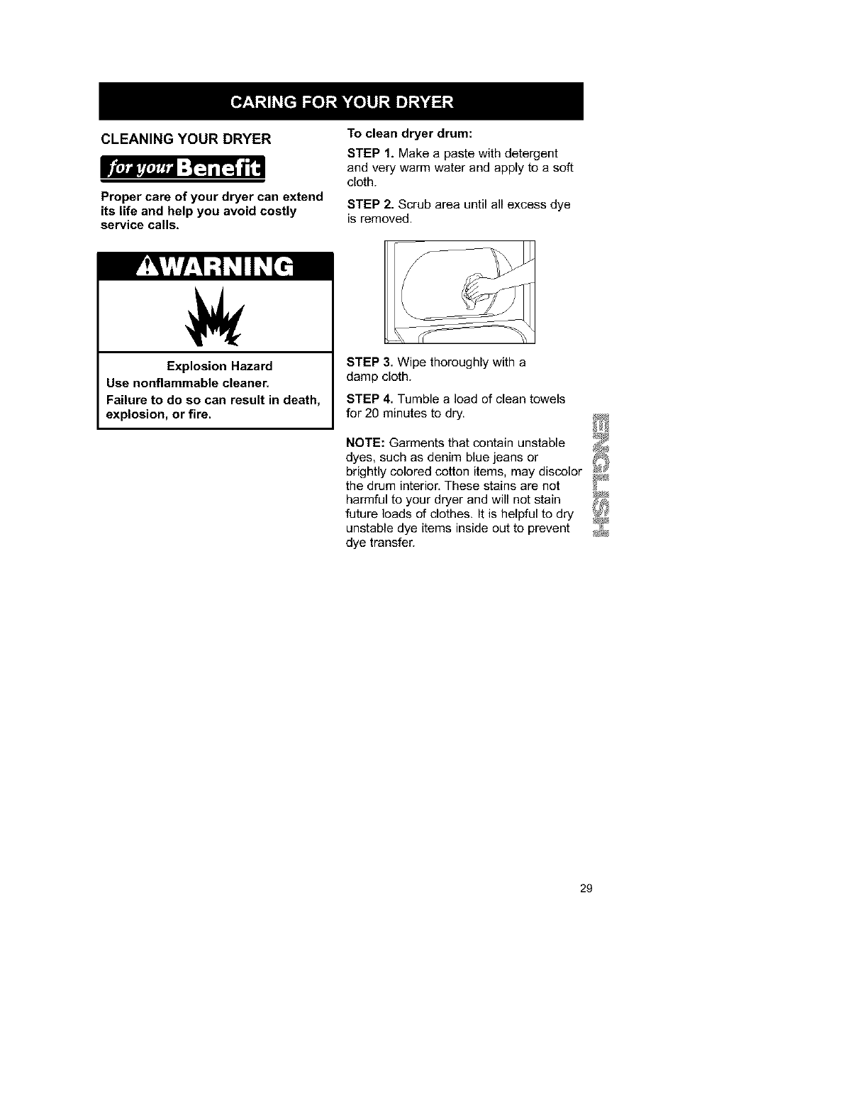
CLEANING YOUR DRYER
Proper care of your dryer can extend
its life and help you avoid costly
service calls.
To clean dryer drum:
STEP 1. Make a paste with detergent
and very warm water and apply to a soft
cloth.
STEP 2. Scrub area until all excess dye
is removed.
Explosion Hazard
Use nonflammable cleaner.
Failure to do so can result in death,
explosion, or fire.
STEP 3. Wipe thoroughly with a
damp cloth.
STEP 4. Tumble a load of clean towels
for 20 minutes to dry.
NOTE: Garments that contain unstable
dyes, such as denim blue jeans or
brightly colored cotton items, may discolor
the drum interior, These stains are not
harmful to your dryer and will not stain
future loads of clothes. It is helpful to dry
unstable dye items inside out to prevent
dye transfer.
29
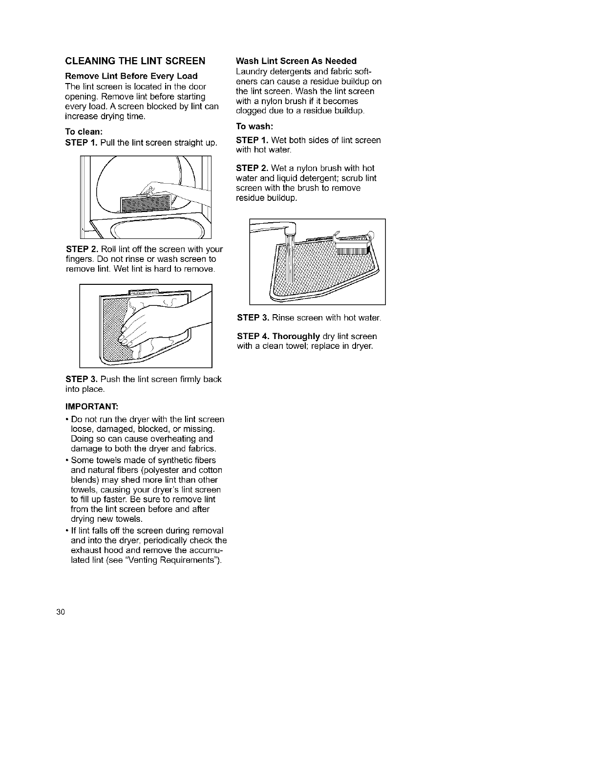
CLEANING THE LINT SCREEN
Remove Lint Before Every Load
The lint screen is located in the door
opening. Remove lint before starting
every load. A screen blocked by lint can
increase drying time.
To clean:
STEP 1. Pull the lint screen straight up.
Wash Lint Screen As Needed
Laundry detergents and fabric soft-
eners can cause a residue buildup on
the lint screen, Wash the lint screen
with a nylon brush if it becomes
clogged due to a residue buildup.
To wash:
STEP 1. Wet both sides of lint screen
with hot water.
STEP 2. Wet a nylon brush with hot
water and liquid detergent; scrub lint
screen with the brush to remove
residue buildup.
STEP 2. Roll lint off the screen with your
fingers. Do not rinse or wash screen to
remove lint. Wet lint is hard to remove.
STEP 3. Rinse screen with hot water.
STEP 4. Thoroughly dry lint screen
with aclean towel; replace in dryer.
STEP 3. Push the lint screen firmly back
into place.
IMPORTANT:
• Do not run the dryer with the lint screen
loose, damaged, blocked, or missing,
Doing so can cause overheating and
damage to both the dryer and fabrics,
• Some towels made of synthetic fibers
and natural fibers (polyester and cotton
blends) may shed more lint than other
towels, causing your dryer's lint screen
to fill up faster. Be sure to remove lint
from the lint screen before and after
drying new towels.
• If lint falls off the screen during removal
and into the dryer, periodically check the
exhaust hood and remove the accumu-
lated lint (see "Venting Requirements").
30
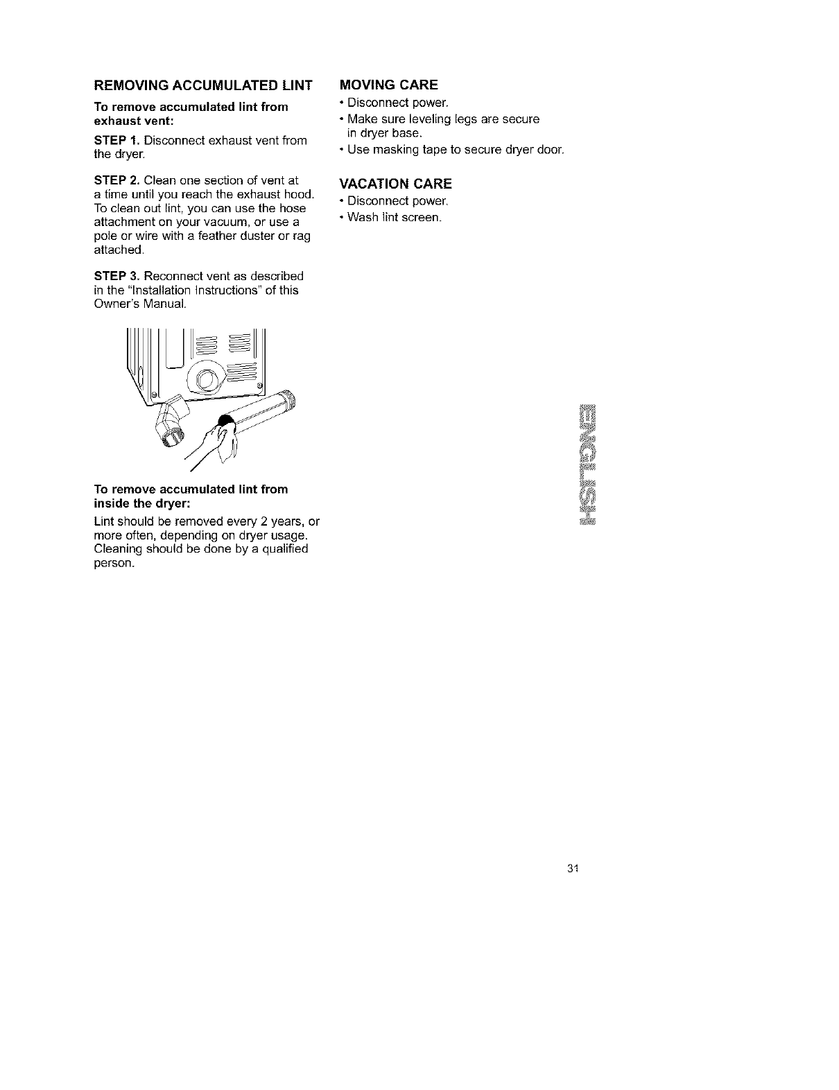
REMOVING ACCUMULATED LINT
To remove accumulated lint from
exhaust vent:
STEP 1. Disconnect exhaust vent from
the dryer.
STEP 2, Clean one section of vent at
a time until you reach the exhaust hood,
To clean out lint, you can use the hose
attachment on your vacuum, or use a
pole or wire with a feather duster or rag
attached.
STEP 3. Reconnect vent as described
in the "Installation Instructions" of this
Owner's Manual.
MOVING CARE
• Disconnect power.
• Make sure leveling legs are secure
in dryer base.
• Use masking tape to secure dryer door.
VACATION CARE
• Disconnect power.
• Wash lint screen.
To remove accumulated lint from
inside the dryer:
Lint should be removed every 2 years, or
more often, depending on dryer usage.
Cleaning should be done by aqualified
person.
31
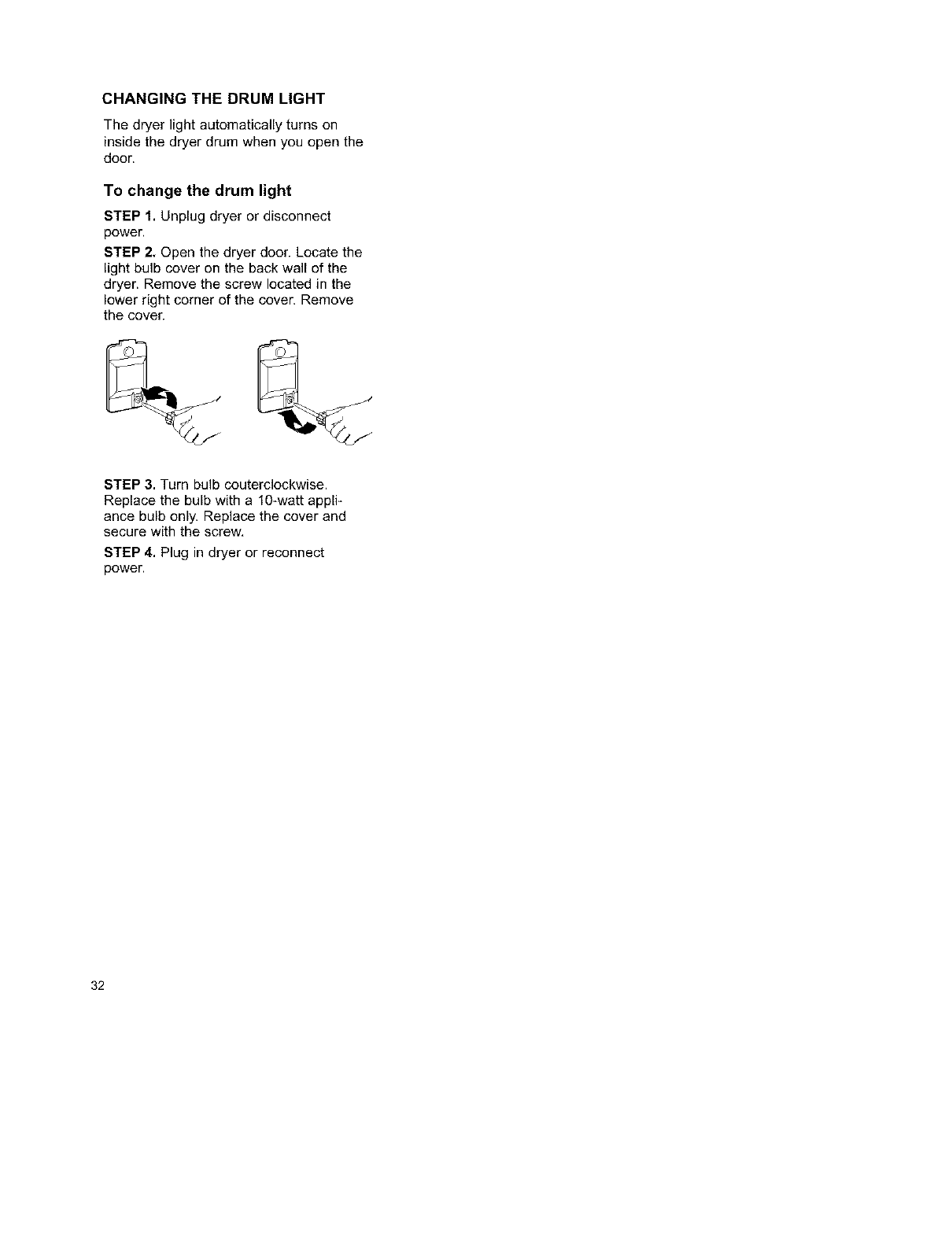
CHANGING THE DRUM LIGHT
The dryer light automatically turns on
inside the dryer drum when you open the
door.
To change the drum light
STEP 1. Unplug dryer or disconnect
power.
STEP 2. Open the dryer door. Locate the
light bulb cover on the back wall of the
dryer. Remove the screw located in the
lower right corner of the cover. Remove
the cover.
STEP 3. Turn bulb couterclockwise.
Replace the bulb with a 10-watt appli-
ance bulb only. Replace the cover and
secure with the screw,
STEP 4. Plug in dryer or reconnect
power.
32
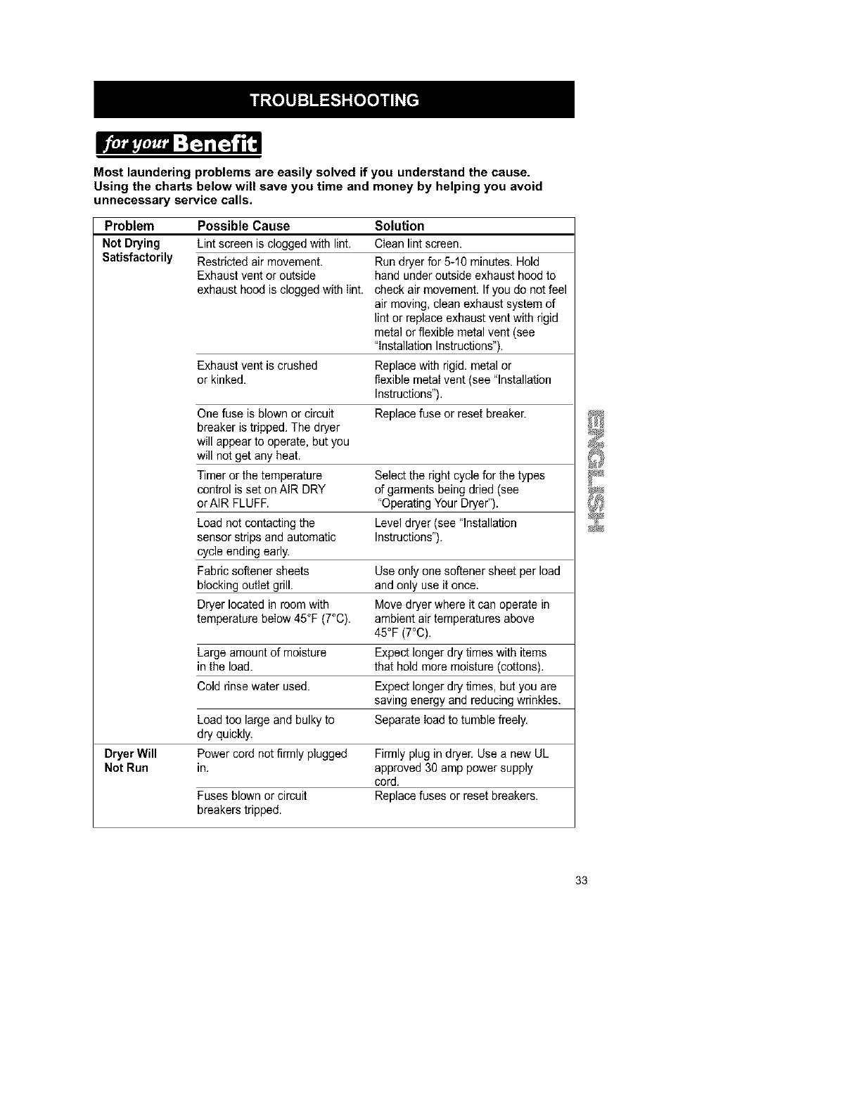
Most laundering problems are easily solved if you understand the cause.
Using the charts below will save you time and money by helping you avoid
unnecessary service calls.
Problem Possible Cause Solution
Not Drying Lint screen is clogged with lint. Clean lint screen.
Satisfactorily Restricted air movement. Run dryer for 5-10 minutes. Hold
Exhaust vent or outside hand under outside exhaust hood to
exhaust hood is clogged with lint. check air movement. If you do not feel
air moving, clean exhaust system of
lint or replace exhaust vent with rigid
metal or flexible metal vent (see
"Installation Instructions").
Exhaust vent is crushed Replace with rigid, metal or
or kinked, flexible metaI vent (see "Installation
Instructions").
One fuse is blown or circuit Replace fuse or reset breaker.
breaker is tripped. The dryer
will appear to operate, but you
will net get any heat.
Timer or the temperature Select the right cycle for the types
control isset on AIR DRY of garments being dried (see
or AIR FLUFF. "Operating Your Dryer").
Load not contacting the Level dryer (see "Installation
sensor strips and automatic Instructions").
cycle ending early.
Fabric softener sheets Use only one softener sheet per load
blocking outlet grill, and only use it once.
Dryer located in room with Move dryer where it can operate in
temperature below 45°F (7°C). ambient air temperatures above
45°F (7°C).
Large amount of moisture Expect longer dry times with items
in the load. that hold more moisture (cottons).
Cold rinse water used. Expect longer dry times, but you are
saving energy and reducing wrinkles.
Load too large and bulky to Separate load to tumble freely.
dry quickly.
Dryer Will Power cord net firmly plugged Firmly plug in dryer. Use a new UL
Not Run in. approved 30 amp power supply
cord.
Fuses blown or circuit Replace fuses or reset breakers.
breakers tripped.
33
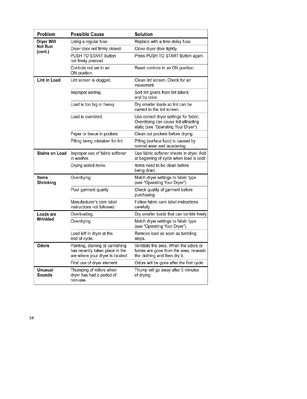
Problem Possible Cause Solution
Dryer Will Using a regular fuse. Replace with a fime-deIay fuse.
Not Run
(cont.) Dryer door notfirmIy closed. Close dryer door tightly.
PUSH TO START Button Press PUSH TO START Button again.
net firmly pressed.
Controls net set in an Reset controls in an ON position.
ON position.
Lint in Load Lint screen is cIogged. Clean lint screen. Check for air
movement.
improper sorting. Sort lint givers from lint takers
and by color.
Load is too big or heavy. Dry smaller loads so lint can be
carried to the lint screen.
Load is overdried. Use correct dryer settings for fabric.
Overdrying can cause lint-attracting
static (see "Operating Your Dryer").
Paper or tissue in pockets. Clean out pockets before drying.
Pilling being mistaken for lint. Pilling (surface fuzz) is caused by
normal wear and laundering.
Stains on Load improper use of fabric softener Use fabric softener sheets in dryer. Add
in washer, at beginning of cycIe when Iead is ceId.
Drying soiled items, items need to be clean before
being dried.
Items Overdrying. Match dryer settings to fabric type
Shrinking (see "Operating Your Dryer").
Poor garment quality. Check quality of garment before
purchasing.
Manufacturer's care label Follow fabric care label instructions
instructions not folIewed, carefuIly.
Loads are Overloading, Dry smaller Ioads that can tumble freel
Wrinkled Overdrying. Match dryer settings to fabric type
(see "Operating Your Dryer").
Load left in dryer at the Remove Ioad as soon as tumbling
end of cycle, stops.
Odors Painting, staining or varnishing Ventilate the area. When the odors or
has recently taken place in the fumes are gone from the area, re-wash
are where your dryer is located, the cIethingand then dry it.
First use of dryer element. Odors will be gone after the first cycIe.
Unusual Thumping of rollers when Thump will go away after 5 minutes
Sounds dryer has had a period of of drying.
non-use.
34
Your purchase has added value because you can depend on Sears HomeCentral ®
for service. With over 12,000 trained repair specialists and access to over 4.2 million
parts and accessories, we have the tools, parts, knowledge and skills to ensure our
pledge: We Service What We Sell.
Sears Maintenance Agreements
Your Kenmore appliance is designed, manufactured and tested to provide years of
dependable operation. Yet any major appliance may require service from time to time.
The Sears Maintenance Agreement offers you an outstanding service program,
affordably priced.
The Sears Maintenance Agreement
•Is your way to buy tomorrow's service at today's prices.
•Eliminates repair bills resulting from normal wear and tear.
• Provides for nomtechnical and instructional assistance.
• Even if you don't need repairs, provides an annual Preventive Maintenance Check,
at your request, to ensure that your appliance is in proper running condition.
Some limitations apply. For more information, call 1-800-827-6655.
For information concerning Sears Canada Maintenance Agreements,
call 1-800-361-6665.
35

36
For rep_r dc_ry-in productslikevaoJums,lawnequipment,and
electronics,callfor the nearestSears Paris and Repair Cenhr.
1-800-488-1222 ._, dayor_ht (U.S.A.only)
_P&IW,SGfILCOITI
For the replacementparts,accessoriesandowner'smanuals
th_ youneedto do-it-yourself,callSears Pa'tsDirectSM?
1-800-366-PAFn" 6a.m.- 11 p.m., 7 days aweek
(1-800-386-7278) (U.S.,e,.only)
_.m_m.coeVpatKIIreet
TO purchaseorinquireabouta Sears ServiceAgreement
orSears MaintenanceAgreement:
1-800-827-6655 (u.s._) 1-800-361-6665 (Canada)
7 a.m.- 5 p.m.,CST, Mort.- S_L 9 a.m. - 8 p.m. EST, M - F,4 p.m.Sat.
Parepedrse_idoderepamodna AuCanadapourseP,,iceenfmn_ais:
dornidlio,y pan] ordenarpiezs_ 1.8004.E.FOYER Mc
1"mS"SU-HOGARsM (1-800.533-6937)
(1-888-784-642-/) www.seers.ca
[SEARS
HomeCentral®
