Kenmore 153336151 User Manual POWER MISER 6 GAS WATER HEATER Manuals And Guides L0010079
KENMORE Water heater, Gas Manual L0010079 KENMORE Water heater, Gas Owner's Manual, KENMORE Water heater, Gas installation guides
User Manual: Kenmore 153336151 153336151 KENMORE POWER MISER 6 GAS WATER HEATER - Manuals and Guides View the owners manual for your KENMORE POWER MISER 6 GAS WATER HEATER #153336151. Home:Plumbing Parts:Kenmore Parts:Kenmore POWER MISER 6 GAS WATER HEATER Manual
Open the PDF directly: View PDF ![]() .
.
Page Count: 28
Owners
Manual
FOR POTABLEWATER
HEATING ONLY
NOT SUITABLE FOR
SPACEHEATING
NOT FOR USE IN
MOBILE HOMES
Model No.
153.336151
153.336251
153.336312
153.336351
153.336412
153.336451
153.336512
153.336551
153.336751
153.336812
153.336851
153.336912
153.336951
30 Gal. Short
40 Gal. Short
30 Gal. High Altitude
30 Gal.
40 Gal. High Altitude
40 Gal.
50 Gal. High Altitude
50 Gal.
30 Gal. Propane (LR)
40 Gal. Propane (LR)
High Altitude
40 Gal. Propane (LR)
50 Gal. Propane (LR)
High Altitude
50 Gal. Propane (LP.)
Caution:
Read and Follow
All Safety Rules and
Operating Instructions
Before First Use of
This Product.
Save this Manual for Future Reference.
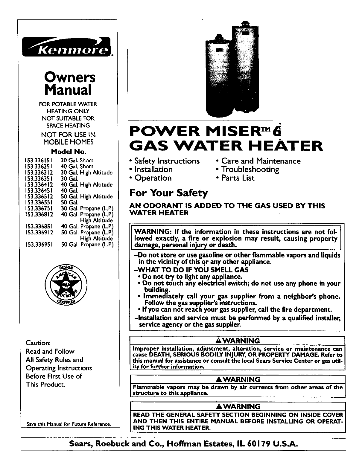
POWER MISERT-"6
GAS WATER HEATER
• Safety Instructions
•Installation
• Operation
• Care and Maintenance
• Troubleshooting
• Parts List
For Your Safety
AN ODORANT IS ADDED TO THE GAS USED BY THIS
WATER HEATER
WARNING: If the information in these instructions are not fol-
lowed exactly, a fire or explosion may result, causing property
damage, personal injury or death.
-Do not sto_ or use gasoline or other flammable vapors and liquids
in the vicinity of this qr any other appliance.
-WHAT TO DO IF YOU SMELL GAS
• Do not try to light any appliance.
•Do not touch any electn'cal switch; do not use any phone in your
building. . .
•Immediately call your gas suppher from a neighbor's phone.
Follow the gas supplier'sinstructions.
If you can not reach your gas supplier, call the fire department.
-Instal.lation and service must be performed by a qualified installer,
service agency or the gas supplier.
_I,WARNING . . I
Improper installation, adjustment, alteration_ service or maintenance can I
cause DEATH, SERIOUS BODILY INJURY, OR PROPERTY DAMAGE. Refer to
this manual for asststance or consult the local Sears Service Center or gas util-
it7 for further information.
&WARNING I
Flammable vapors may be drawn by air currents from other areas of the
structure to this appliance.
_,WARNING
READ THE GENERAL SAFETY SECTION BEGINNING ON INSIDE COVER
AND THEN THIS ENTIRE MANUAL BEFORE INSTALLING OR OPERAT-
ING THIS WATER HEATER.
Sears, Roebuck and Co., Hoffman Estates, IL 60179 U.S.A.
Safe Precautions
I i T ;i.AWARNING
II_pr6perl installatmn, adjustment, alteration, service or I
Irrtalnten_ncq can cause DEATH, SERIOUS BODILY I
I INJURY, OR PROPERTY DAMAGE. Refer to this manu- I
I a[ foe asslsta_nce:or consult your local Sears Service I
IC_nter for further information. I
i
i _ _ ._"WARNING
WATER HEATERS EQUIPPED FOR ONE TYPE GAS
ONLY: This water heater is equipped for one type gas
only. Check the model rating plate near the gas control
valve for the correct gas. DO NOT USE THIS WATER
HEATER WITH ANY GAS OTHER THAN THE ONE
SHOWN ON THE MODEL RATING PLATE. Failure to
use the correct gas can causeproblems which can result in
DEATH, SERIOUS BODILY INJURY, OR PROPERTY
DAMAGE. If you have any questions or doubts consult
your gassupplieror local utility.
AWARNING
INSTALLATIONS IN AREAS WHERE FLAMMABLE LIQ-
UIDS (VAPORS) ARE LIKELY TO BE PRESENT OR
STORED (GARAGES, STORAGE, AND UTILITY AREAS,
ETC): Flammable liquids (such as gasoline, solvents,
propane (LP) or butane, etc.), all of which emit flammable
vapors, may be impropedy stored or used in such areas.
The gaswater heater pilot light or main burner can ignite
such vapors. The resulting flashback and fire can cause
death or serious burns to anyone in the area, as well as
property damage.
If installation in such areas is your only option, then the
installation must be accomplishedin a way that the pilot
flame and main burner flame are elevated from the floor
at least 18 inches.While this may reduce the chancesof
flammable vapors from afloor spillbeing ignited, gasoline
and other flammable substancesshouldnever be stored or
used in the same room or area containing a gas water
heater or other open flame or spark producingappliance.
NOTE: Flammable vapors may be drawn by air currents
from other areasof the structure to the appliance.
_WARNING
If this water heater will be used in beauty shops,barber
shops, cleaning establishments, or salf-service laundries
with dry cleaning equipment, it is imperative that the
water heater or water heaters be installed so that com-
bustion and ventilation air be taken from outside these
areas. Refer to the "Locating The New Water Heater"
section of this manual and also the latest edition of the
National Fuel Gas Code, ANSI Z223.1, also referred to as
NFPA 54 for specificsprovided concerningair required,
AWARNING
A fire can start if €orals suchas clothing,
cleaningmaterials, or flammable liquidsare placed against
or next to the water heater,
,IW RNIN G -
At the time of manufacture this water heater was pro.
vided with acombination temperature.pressures relief
valve certified by a nationally recognized testing labora-
tory that maintains periodic inspection of production of
listed equipment or materials, as meeting the require-
ments for Relief Valves and Automatic Gas Shutoff
Devices for Hot Water Supply Systems, and the latest
edition of ANSI Z21.22 and the code requirements of
ASME. If replaced, the valve must meet the require-
ments of local codes, but not less than a combination
temperature and pressurerelief valve certified as meet-
ing the requirements for Relief Valves and Automatic
Gas Shutoff Devices for Hot Water Supply Systems,
ANSI Z21.22 by a nationally recognized testing laborato-
ry that maintains periodic inspection of production of
listed equipment or materials.
The valve must be marked with a maximum set pressure
not to exceed the marked hydrostatic working pressure
• I
of the water heater (150 Ibs.lsq. in.) and a discharge
capacity not less than the water heater input rate as
shown on the model rating plate. (Electric heaters
watts divided by 1000x 3415 equal BTU/Hr. rate.)
Your local jurisdictional authority, while mandating the
use of a temperature.pressure relief valve complying
with ANSI Z21.22 and ASME, may require a valve model
different from the one furnishedwith the water heater.
Compliance with such local requirements must be satis-
fied by the installer or end user of the water heater with
a locally prescribed tumperature-pressure relief valve
installed in the designatedopeningin the water heater in
placeof the factory furnishedvalve.
For safe operation of the water heater, the relief valve
must not be removed from it's designated opening or
plugged.
The temperature-pressure relief valve must be installed
directly into the fitting of the water heater designatedfor
the relief valve. Position the valve downward and provide
tubing so that any dischargewill exit only within 6 inches
above, or at any distance below the structural floor. Be
certain that no contact is made with any live electrical
)art. The discharge opening must not be blocked or
reduced in size under any circumstances. Excessive
length, over 30 feet, or useof more than four elbowscan
cause restriction and reduce the discharge capacity of
the valve.
No valve or other obstruction is to be placed between
the relief valve and the tank. Do not connect tubing
directly to dischargedrain unlessa 6" air gap is provided.
To prevent bodily injury, hazard to life, or property dam-
age, the relief valve must be allowed to dischargewater
in quantities should circumstances demand. If the dis-
charge pipe is not connected to adrain or other suitable
means, the water flow may causeproperty damage.
The Discharge Pipe:
Must not be smaller in sizethan the outlet pipe sizeof
the valve, or have any reducing couplings or other
restrictions.
Must not be pluggedor blocked.
Must be of material listed for hot water distribution.
Must be installed so as to allow complete drainage of
both the temperature-pressure relief valve, and the
dischargepipe.
Must terminate at an adequate drain.
Must not have any valve between the relief valve and
tank.
2
Safety Precautions
_t,WARNING
A gas water heater cannot operate properly without the
correct amount of air for combustion. Do not install in a
confined area such acloset, unless you provide air as
shownin the "Locating The New Water Heater" section.
Never obstruct the flow of ventilation air. If you have any
doubts or questionsat all, call your gascompany. Failure
to providethe proper amount of combustionair can result
in a fire or explosion and can cause DEATH, SERIOUS
BODILY INJURY,OR PROPERTY DAMAGE.
AWARNING
This water heater must not be installed directly on car-
peting. Carpeting must be protected by a metal or wood
_anel beneath the appliance extending beyond the full
width and depth of the appliance by at least 3 inches
(76.2mm) in any direction, or if the appliance is installed
in an alcoveor closet, the entire floor must be covered by
the panel. Failure to heed this warning may result in a
fire hazard.
AWARNING
HOTTER WATER CAN SCALD: Water heaters are
intended to produce hot water. Water heated to a tem-
perature which will satisfy clothes washing, dish washing,
and other sanitizing needs can scald and perm..a.nently
injure you upon contact. Some people are more likely to
be permanently injured by hot water than others. These
includethe elderly, children, the infirm, or physically/men-
tally handicapped.If anyone usinghot water in your home
fits into one of these groupsor if there is a local code or
state law requiring a certain temperature water at the hot
water tap, then you must take specialprecautions. In addi-
tion to usingthe lowest possibletemperature set_ng that
satisfies your hot water needs, a means suchas a mixing
valve, shouldbe usedat the hot water taps usedby these
people or at the water heater. Mixing valves are available
at plumbing supply or hardware stores. Follow manufac-
turers instructions for installation of the valves. Before
changingthe factory setting on the thermostat, read the
"Temperature Regulation"sectionin this manual.
AWARNING
Soot build-up indicates aproblem that requires correc-
tion before further use. Turn "off" gas to water heater
and leave "off" until repairs are made, because failure to
correct the cause of the sooting can result in a fire or
explosion causing DEATH, SERIOUS BODILY INJURY,
OR PROPERTY DAMAGE.
AWARNING
VENT DAMPERS - Any vent damper,whether it isoperat-
ed thermally or otherwise must be removed if its use
inhibitsproper drafting of the water heater.
Thermally Operated Vent Dampers: Gas-fired water
heaters having thermal efficiency in excess of 80% may
produce a relatively low flue gas temperature. Suchtem-
peratures may not be high enoughto properly open ther-
maily operated vent dampers.This wouldcausespillageof
flue gasesand may causecarbon monoxidepoisoning.
Vent dampers must bear evidence of certification as com-
plying with the latest edition of American National
Standard ANSI Z21.68 (ANSI Z21.66 & 67, respectively,
cover electrically and mechanically actuated vent
dampers). Before installation of any vent damper, consult
your local Sears Service Center or the gas utility for fur-
ther information.
&WARNING
• The appliance and its individualshutoffvalve must be dis-
connected from the gas supplypiping systemduring any
pressure testing of the gas system at test pressuresin
excessof I/2 poundper squareinch (3.5kPa).
•The appliance must be isolatedfrom the gas supplypip-
ing system by closing its individualmanual shutoff valve
during any pressuretesting of the gas supplypiping sys-
tem at test pressuresequal or less than I/2 pound per
squareinch (3.SkPa).
AWARNING
BEFORE LIGHTING [PROPANE (L.P.) GAS WATER
HEATERS]: Propane (L.R) gas is heavier than air. Should
there be a leak in the system,the gaswill settle near the
ground. Basements, crawl spaces, skirted areas under
mobile homes (even when ventilated), closets and areas
below groundlevel will serve as pocketsfor the accumula-
tion of this gas. Before attempting to light or relight the
water heater's pilot or turning on a nearby electrical light
switch, be absolutely surethere is no accumulated gas in
the areL Searchfor odor of gas by sniffingat ground level
in the vicinity of the appliance. If odor is detected, follow
steps indicated at "For Your Safety" on the cover page of
this manualthen leavethe premises.
A, WARNING
Chemical vapor corrosion of the flue and vent system
may occur if air for combustion containscertain chemical
vapors.Spray can propellants,cleaningsolvents,refHgera.
tot and air conditioner refrigerants, swimming pool
chemicals, calcium and sodium chloride, waxes, bleach,
and processchemicals are typical compounds which are
potentially corrosive.
_,WARNING
Obstructed or deteriorated vent systems may present a
serous health riskor asphyxation.
Safety Precautions continued on page 4
3
Safety Precautions
I&WARNING
The water heater with draft hood installed must be prol>
erly vented to a chimney which terminates outdoors.
Never operate the water heater unlessit is vented.to the
outdoors and has adequate air supply to avoid risks of
improper operation, explosionor asphyxiation.
_,WARNING
Minimum clearances between the water heater and com-
bustible constructionare I" at the sidesand rear, 4" at the
front,and6" ftom the vontpipe.Clearancefram tbe top of the
jacketis I B"on mostmodel_ Notethat a lesserdimensionmay
Ibe allowedon somemodels Referto the label on the water
heateradjacentto the gascontrolvalveforalldearance_
.... ? -'-__UTION
WATER HEATERS EVENTUALLY LEAK_ Installation of
the water heater must be accomplishedin such a manner
that if the tank or any connectionsshould leak, the flow
of water will not causedamage to the structure. For this
reason,it isnot advisableto Installthe water heater in an
attic or upper floor. When such locations cannot be
avoided, a suitable drain pan should be installed under
the water heater. Drain pansare available at your local
Sears store. Such adrain pan must be not greater than
I/2 inchesdeep, havea minimum length and width of at
least 2 inches greater than the water heater dimensions
and must be piped to an adequate drain. The pan must
not restrict combustionair flow. Under no circumstances
is the manufacturer or Sears to be held liable for any
water damage in connectionwith thiswater heater.
IAWARNING I
Do not use this appliance if any part of.it has been under J
water. |mmedi.ately call aSears Service Technician to I
inspectthe appl_nce and to replacethe gas control or anyI
part of the burner systemwhich hasbeen underwater.
AWARNING
HYDROGEN GAS: Hydrogen gascan be producedin ahot
water system that has not been usedfor a long period of
time (generally two weeks or more). Hydrogen gas is
extremely flammable and explosive.To prevent the possi-
bility of injury under these conditions,we recommend the
hot water faucet be opened for several minutes at the
kitchen sink before any electrical appliances which are
connected to the hot water system are used (such as a i
dlshwasber or washing machine). If hydrogen gas is pre.-I
sent,there will probablybe an unusualsounds|miler to sur
escaping through the pipe as the hot wnter faucet is
opened. There must be no smoking or open flame near
the Paucetat the time it isopen.
&WARNING
INSULATING JACKETS: When installing an external
water heater insulationjacket on agaswater heater:
•DO NOT coverthe temperetere_pressuro reliof vaive.
•DO NOT put insulation over any part of the top of the
gaswater heater.
•DO NOT put insulation over the gascontrol valve or gas
control valvelburner cover, or any accessareas to the
burner.
•DO NOT let insulation around the gas water heater to
get within 8 inches of the floor (air must get to the
burner).
•DO NOT cover or remove operating !nstroctioos, and
safetyrelated warning labelsand matonais affixed to the
water heater.
Failure to heed this will result in the possibilityof a fire or
explosion.
4
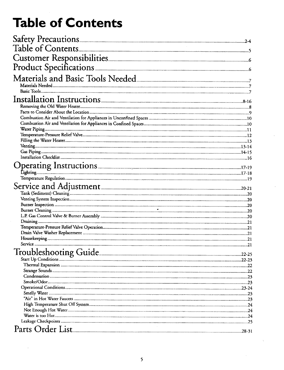
Table of Contents
Safety Precautions ............................................................................................................................................2_
Table of Contents ................................................................................................................................................5
Customer Kesponsibilities .......................................................................................................................6
Product Specifications ..................................................................................................................................6
Materials and Basic Tools Needed ...............................................................................................7
Materials Needed ...................................................................................................................................................................... 7
Basic Tools ................................................................................................................................................................................ 7
Installation Instructions ........................................................................................................................8-16
Removing the Old Water Heater ............................................................................................................................................... 8
Facts to Consider About the Location ....................................................................................................................................... 9
Combustion Air and Ventilation for Appliances in Unconfined Spaces ................................................................................... 10
Combustion Air and Ventilation for Appliances in Confined Spaces ....................................................................................... 10
Water Piping ........................................................................................................................................................................... l 1
Temperature-Pressure Relief Valve ........................................................................................................................................... 12
Filling the Water Heater .......................................................................................................................................................... 13
Venting .............................................................................................................................................................................. 13-14
Gas Piping ......................................................................................................................................................................... 14-15
Installation Checklist .............................................................................................................................................................. 16
A__peratin_ Instructions .........................................................................................................................17-19
_"'_Eighting................................................................................. "............................................................................................ 17-18
Temperature Regulation .......................................................................................................................................................... 19
Service and Adjustment ......................................................................................................................20-21
Tank (Sediment) Cleaning ...................................................................................................................................................... 20
Venting System Inspection ...................................................................................................................................................... 20
Burner Inspection ................................................................................................................................................................... 20
Burner Cleaning ........................................................................................ 2........................................................................... 20
L.P. Gas Control Valve & Burner Assembly ............................................................................................................................ 20
Draining ................................................................................................................................................................................. 21
Temperature-Pressure Relief Valve Operation .......................................................................................................................... 21
Drain Valve Washer Replacement ........................................................................................................................................... 21
Housekeeping ......................................................................................................................................................................... 21
Service .................................................................................................................................................................................... 21
Troubleshooting Guide ........................................................................................................................22-25
Start Up Conditions .......................................................................................................................................................... 22-23
Thermal Expansion .............................................................................................................................................................. 22
Strange Sounds ..................................................................................................................................................................... 22
Condensation ....................................................................................................................................................................... 23
Smoke/Odor ......................................................................................................................................................................... 23
Operational Conditions ..................................................................................................................................................... 23-24
Smelly Water ........................................................................................................................................................................ 23
"Air" in Hot Water Faucets ................................................................................................................................................... 23
High Temperature Shut Off System ...................................................................................................................................... 24
Not Enough Hot Water ........................................................................................................................................................ 24
Water is too Hot ................................................................................................................................................................... 24
Leakage Checkpoints .............................................................................................................................................................. 25
Parts ---OrderList...............................................................................................................................................28-31
Customer Responsibilities
Thank You for purchasinga Sears water heater:
Properly installed and maintained, it should give you years of
trouble free service. If you should decide that you want the new
water heater professionally installed by Sears call the local Sears
Service Center or any Sears store. They will arrange for prompt,
quality installation by Sears authorized contractors.
Abbzevlatlons Found In This [nstt-uctlon Manual
I.A.S. -International Approval Services, A Division of CSA
A.N.S,L -American National Standards Institute
N.EP.A. -National Fire Protection Association
AWARNING
This gas-fired water heater is design certified by the
International Approval Services, A Division of CSA under
American National Standard/CSAStandardfor GasWater
Heaters ANS Z21.10.1 ' CSA 4.1 (latest edition). The
installation must conform with this manual, Local Codes
and with the latest edition of the National Fuel GasCode
ANSI 7-223.1.
This publicationis availablefrom your local g.oy..emmentol
public library, gas company, or by writing NFPA,
Batterymarch Park, Quincy,MA 02269.
•Read the "Safety Precautions" section, pages 2 through 4 of
this manual first and then the entire manual carefully. If you
don't follow the safety rules, the water heater will not operate
properly. It could cause DEATH, SERIOUS BODILY
INJURY AND/OR PROPERTY DAMAGE.
. . d:,,.. . . .
Th_s manual coW_ns Instmcuons for the mstallanon, opera-
tion, and maintenance of the gas-fired water heater. It also
contains warnings through out the manual that you must read
and be aware of. All warnings and all instructions axe essential
to the proper operation of the water heater and your safety.
Since we cannot put everything on the first k'w pages, READ
THE ENTIRE MANUAL BEFORE ATTEMPTING TO
INSTALL OR OPERATE THE WATER HEATER.
•The installation must conform with the instructions in this
manual; gas company rules; and Local Codes, or in the
absence of Local Codes, with the latest edition of the National
Fuel Gas code, ANSI Z223.1, also referred to as NFPA 54.
This publication is available from your local government or
public library or gas company or by writing NFPA,
Batrerymarch Park, Quincy, MA 02269.
• If after reading this manualyou have any questions or do not
understand any portion of the instructions, call the Sears
Service Center.
• Carefully plan the place where you are goinl_ to put the water
heater. Correct combustion, vent action, ann vent pipe instal-
lation are very important in preventing death from possible
carbon monoxide poisoning and fires.
Examine the location to ensure the water heater complies with
the "Facts to Consider About the Location" section in this
manual.
• For California installation this water heater must be braced,
anchored, or strapped to avoid falling or moving during an
earthquake. See instructious for correct installation proce-
dures. Instructions may be obtained from your local dealer,
wholesaler, public utilities or California Office of the State
Architect, 400 P Street, Sacramento, CA 95814.
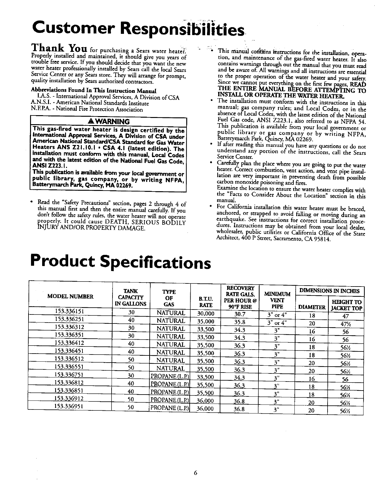
Product Specifications
MODELNUMBER
153.336151
153.336251
153.336312
153.336351
153.336412
153.336451
153.336512
153.336551
153.336751
153.336812
153.336851
153.336912
153.336951
TANK
CAPACITY
IN GALLONS
30
40
30
30
40
40
50
50
3O
40
4O
50
50
TYPE
OF
GAS
NATURAL
NATURAL
NATURAL
NATURAL
NATURAL
NATURAL
NATURAL
NATURAL
PROPANE (L.E)
PROPANE(L.P.)
PROPANE (L.P.)
PROPANE(L.P.)
PROPANE (L.E)
B.ZU.
RATE
30,000
35,000
33,500
33,500
35,500
35,500
35,500
35!500
331500
35,_00
35,_00
36,000
36,000
RECOVERY
RATE GM_
PER HOUR @
90°F RISE
30.7
35.8
34.3
34.3
36.3
36.3
36.3
36.3
34.3
36.3
36.3
36.8
36.8
PIPE
3" or 4"
3" or 4"
3"
3"
3"
3"
3"
3"
3"
3"
3"
3"
3"
DIMENSIONS IN INCHES
HEIGHTTO
DIAMETER JACKETTOP_
18 47
20 47½
16 56
16 56
18 56_
18 56½
20 56½
20 56_
16 56
18 56½
18 56½
20 56½
20 56½
6
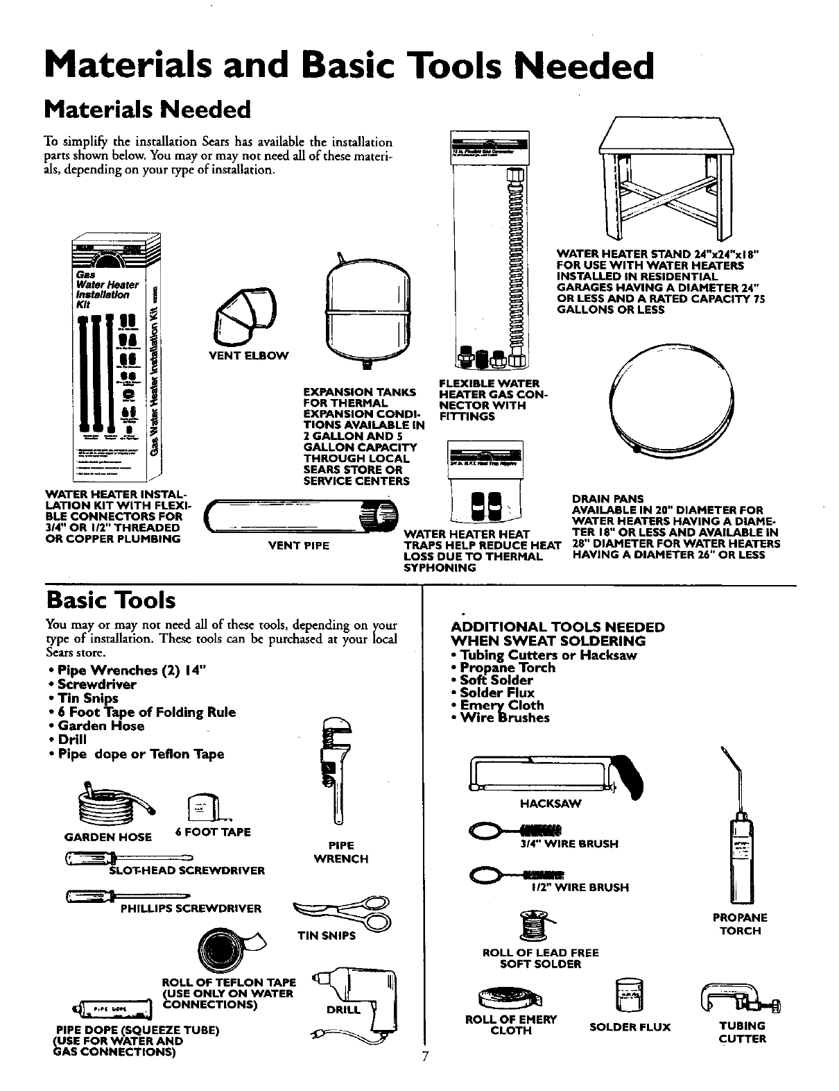
Materials and Basic Tools Needed
Materials Needed
To simplify the installation Sears has available the installation
parts shown below. You may or may not need all of these materi-
als, depending on your type of installation.
WATER HEATER INSTAL-
LATION KIT WITH FLEXI- f
BLE CONNECTORS FOR
314" OR I/2" THREADED
OR COPPER PLUMBING
EXPANSION TANKS
FOR THERMAL
EXPANSION CONDI-
TIONS AVAILABLE IN
2GALLON AND 5
GALLON CAPACITY
THROUGH LOCAL
SEARS STORE OR
SERVICE CENTERS
FLEXIBLE WATER
HEATER GAS CON-
NECTOR WITH
Fll-rlNGS
WATER HEATER STAND 24"x24"x18"
FOR USE WITH WATER HEATERS
INSTALLED IN RESIDENTIAL
GARAGES HAVING A DIAMETER 24"
OR LESS AND A RATED CAPACITY 75
GALLONS OR LESS
VENT PIPE
DRAIN PANS
AVAILABLE IN 20" DIAMETER FOR
WATER HEATERS HAVING A DIAME-
WATER HEATER HEAT TER 18" OR LESS AND AVAILABLE IN
TRAPS HELP REDUCE HEAT 28" DIAMETER FOR WATER HEATERS
LOSS DUE TO THERMAL HAVING A DIAMETER 26" OR LESS
SYPHONING
Basic Tools
You may or may not need all of these tools, depending on ycour
type of installation. These tools can be purchased at your local
Sears store.
• Pipe Wrenches (2) 14"
•Screwdriver
•Tin Snips
•6 Foot Tape of Folding Rule
•Garden Hose
•Drill
•Pipe dope or Teflon Tape
GARDEN HOSE 6 FOOT TAPE
SLOT-HEAD SCREWDRIVER
PIPE
WRENCH
PHILLIPS SCREWDRIVER
ROLL OF TEFLON TAPE
(USE ONLY ON WATER
CONNECTIONS)
PIPE DOPE (SQUEEZE TUBE)
(USE FOR WATER AND
GAS CONNECTIONS)
TIN SNIPS
DRILL
ADDITIONAL TOOLS NEEDED
WHEN SWEAT SOLDERING
Tubing Cutters or Hacksaw
Propane Torch
Soft Solder
• Solder Flux
Emery Cloth
Wire Brushes
HACKSAW
3/4" WIRE BRUSH
112"WIRE BRUSH
ROLL OF LEAD FREE
SOFT SOLDER
ROLL OF EMERY
CLOTH
8
SOLDER FLUX
7
PROPANE
TORCH
TUBING
CUTTER
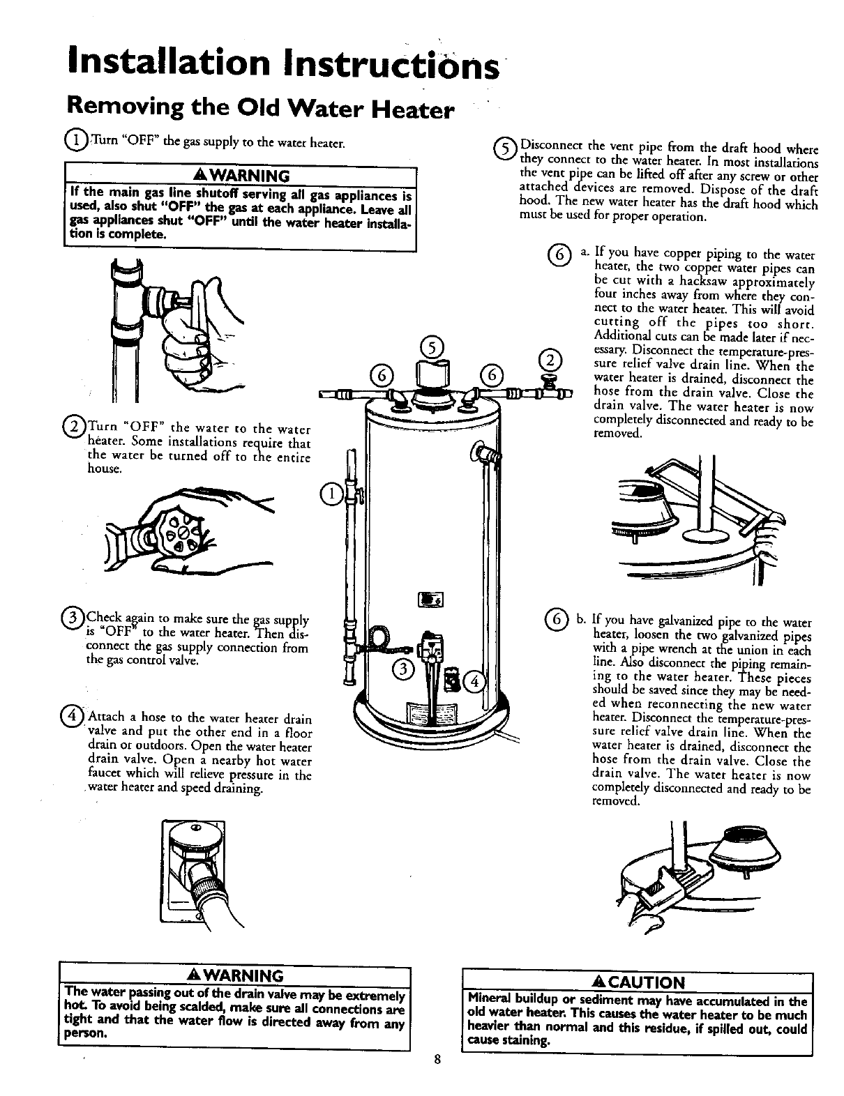
Installation InstructiOns
Removing the Old Water Heater
Turn gas supply to water
"OFF" the the heater.
AWARNING .[
If the main gas line shutoff serving all gas apphancesis
used, also shut "OFF" the gasat each appliance.Leaveall
gas appliances shut "OFF" until the water heater installa-I
Ition scomp ete. I
Turn water to water
*4OFF I_ the the
heater. Some installations require that
the water be turned off to the entire
house.
Check a_in to make sure the gas supply
is OFF to the water heater. Then dis-
Connect the gas supply connection from
the gas control valve.
Attach hose the heater drain
ato water
"valve and put the other end in afloor
drain or outdoors. Open the water heater
drain valve. Open a nearby hot water
faucet which will relieve pressure in the
.water heater and speed draining.
®
Disconnect the vent pipe from the draft hood where
they connect to the water heater. In most installations
the vent pipe can be lifted off after any screw or other
attached devices are removed. Dispose of the draft
hood. The new water heater has the draft hood which
must be used for proper operation.
®a, [f you have copper piping to the water
heater, the two copper water pipes can
be cut with a hacksaw approximately
four inches away from where they con-
nect to the water heater. This willavoid
cutting off the pipes too short.
Additional cuts can be made later if nec-
essary. Disconnect the temperature-pres-
sure relief valve drain line. When the
water heater is drained, disconnect the
hose from the drain valve. Close the
drain valve. The water heater is now
completely disconnected and ready to be
removed.
Qb. If you have galvanized pipe to the water
heater, loosen the two galvanized pipes
with a pipe wrench at the union in each
line. Also disconnect the piping remain-
ing to the water heater. These pieces
should be saved since they may be need-
ed when reconnecting the new water
heater. Disconnect the temperature-pres-
sure relief valve drain line. When the
water heater is drained, disconnect the
hose from the drain valve. Close the
drain valve. The water heater is now
completely disconnected and ready to be
removed.
J_WARNING
The water passingout of the drain valvemay be extremely
I hot. To avoid being scalded, make sureall connectionsare I
[ tight and that the water flow is directed away from any [
]person. I
A, CAUTION J
Mineral buildupor sediment may haveaccumulated in the [
old water heater. This causesthe water heater to be much
heavier th.an normal and this residue, if spilledout, could
causestoning.
Installation Instructions (cont'd)
Facts to Consider About the
Location
You should carefully choose an indoor location for the new
water heater, because the placement is a very important consid-
eration for the safety of the occupants in the building and for
the most economical use of the appliance. This water heater is
not for use in mobile homes or outdoor installation.
Whether replacing an old water heater or putting the water
heater in a new location, the following critical points must be
observed.
•The location selected should be indoors as close as practical to
the gas vent or chimney to which the water heater vent is
going to be connected, and as centralized with the water pip-
ing system as possible. The water heater, as all water heaters,
will eventually leak. Do not install without adequate drainage
provisions where water flow will cause damage.
ACAUTION
WATER HEATERSEVENTUALLY LEAK: Installationof the
water heater must be accomplishedin suchamannerthat if
the tank or anyconnectionsshouldleak,the flowof water will
not causedamageto the structure. For this mason, it is not
advisableto installthe water heaterin an atticor upperfloor.
When suchlocationscannotbe avoided,a suitabledrainpan
shouldbe installedunder the water heater. Drain pansare
availableat your local Searsstore. Suchadrainpan must be
not greaterthan 1½inchesdeep,havea minimumlengthand
width of at least2 inchesgreaterthanthe water heaterdimen-
sionsand must be pipedto an adequatedreirLThe panmust
notrestrictcombustionair flow.Under no circumstancesisthe
manufactureror Searsto be held liablefor anywater damage
in€onee_on with this water heater.
_,WARNING
INSTALLATIONSIN AREASWHERE FLAMMABLELIQUIDS
(VAPORS) ARE LIKELY TO BE PRESENT OR STORED
(GARAGES, STORAGE, AND UTILITY AREAS, ETC):
Flammableliquids(suchasgasoline,solvents,propane(LP) or
butane, etc.), all of which emit flammable vapors,may be
improperlystoredor usedin sucharea_ The gaswater heater
pilotlightor mainburnercanignitesuchvapor_The resulting
flashbackandfire can cause death or seriousbumsto anyonein
the area,aswellaspropertydamage.
If installationin suchareasisyouronlyoption,then the installa-
tion must be accomplishedin a waythat the pilot flame and
mainburnerflameam elevatedfromthe floorat least18inche_
While this mayreducethe chancesof flammablevaporsfroma
floorspillbeingignited,gasolineandother Ilammablesubstances
shouldneverbe storedor usedin the sameroom or area con-
tainingagaswater heaterorotheropenflameor sparkproduc-
lagappliance.
NOTE: Flammablevaporsmay be drawn by air currentsfrom
otherareas ofthe structureto the appliance.
_,WARNING
Propellantsof aerosolspraysandvolatilecompounds,(clean-
ers,chlorinebasedchemicals,refrigerants,etc.) inadditionto
being highlyflammable inmanycases,will alsochangeto cor-
rosive hydrochloric acid when exposedto the combustion
productsof the water h_ter. The resultscan be hazardous,
and alsocauseproductfailure.
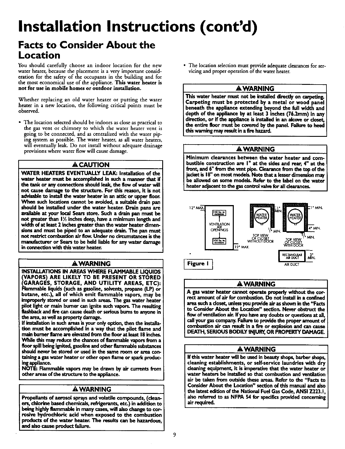
•The location selection must provide adequatedearances for ser-
vicing and proper operation of the water heater.
&WARNING
Thiswater heater must not be installeddirectlyon carpeting.
Carpeting must be protected by ametal or wood panel
beneath the appliance extending beyondthe full width and
depth of the appliance by at least3 inches(76.2mm) in any
direction.,or if the applianceis installedin an alcoveor closet,
the entire floormust be coveredby the panel.Failureto heed
this warningmayresultinafire hazard.
AWARNING
Minimum clearancesbetween the water heater and com-
bustibleconstructionare I" at the sidesand rear, 4" at the
front,and6" fromthe vent pipe.Clearancefromthe top ofthe
jacketis 18"on mostmodel_ Notethat a lesserdimensionmay
be allowedon some models.Referto the label onthe water
heateradjacentto the gascontrolvalveforalldearance_
12" MAX._
VENTI_TION
OPENINGS
Figure I IAIRDUCT
&WARNING
A gaswater heatercannotoperateproperlywithoutthe cor-
rect amount ofair for combestio_ Do not install inaconfined
areasuch acloset,unlessyou provideair as showninthe "Facts
to ConsiderAbout the Location"section.Neverobstructthe
flowof ventilationair. if you haveanydoubtsor questionsat all,
callyour gascompany.Failureto providethe properamountof
combustionair can result in a fire or explosionandcancause
DEATH,SERIOUSBODILYINJUR_,OR PROPERTYDAMAGE,
_,WARNING
If this water heaterwill be usedin beautyshops,barbershops,
cleaningestablishments,or self-servicelaundrieswith dry
cleaningequipment,it is imperativethat the water heateror
water heatersbe installedso that cembus_on andventilation
air he taken from outsidethesearea_ Referto the "Facts to
ConsiderAboutthe Location"sectionof this manualandalso
the latesteditionof the NationalFuelGasCode,ANSI Z223.1,
alsoreferredto as NFPA 54 for specificsprovidedconcerning
air required.
Installation InstructiOns(cont'd)
Combustion Air and Ventilation
for Appliances Located in
Unconfined Spaces
Unconfined Space is a space whose volume is not less than 50
cubic feet per 1,000 Btu per hour of the aggregate input rating
of all appliances installed in that space. Rooms communicating
directly with the space in which the appliances are installed,
through openings not furnished with doors, are considered a
part of the unconfined space
In unconfined spaces in buildings, infiltration may be adequate
to provide air for combustion, ventilation and dilution of flue
gases. However, in buildings of tight construction (for example,
weather stripping, heavily insulated, caulked, vapor barrier, etc.),
additional air may need to be provided using the methods
described in Combustion Air and Ventilation for Appliances
Located in Confined Spaces, b.
Combustion Air and Ventilation
for Appliances Located in
Confined Spaces
Confined Space is a space whose volume is less than 50 cubic
feet per 1,000 Btu per hour of the aggregate input rating of all
appliances installed in that space.
a. ALL AIR FROM INSIDE BUILDINGS:
(See Page 8 Figure 1, and Figure 2 below)
The confined space shall be provided with two permanent
openings communicating directly with an additional room(s)
of sufficient volume so that the combined volume of all
spaces meets the criteria for an unconfined space. The total
input of all gas utilization equipment installed in the com-
bined space shall be considered in making this determination.
Each opening shall have a minimum free area of one square
inch pet 1,000 BTU per hour of the total input rating of all
gas utilization equipment in the confined space, but not less
than 100 square inches. One opening shall commence within
12 inches of the top and one commencing within 12 inches
of the bottom of the enclosure.
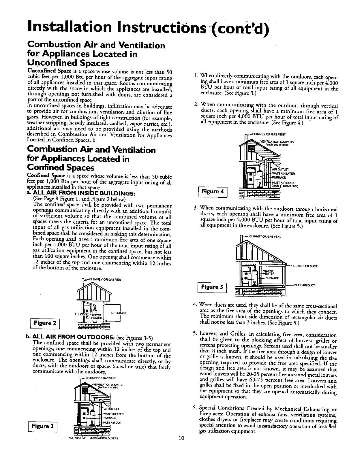
1. When directly communicating with the outdoors, each open-
ing shall have a minimum free area of I square inch per 4,000
BTU pet hour of total input rating of all equipment in the
enclosure. (See Figure 3.)
2. When communicating with the outdoors through vertical
ducts, each opening shall have a minimum free area of 1
square inch per 4,000 BTU per hour of total input rating of
all equipment in the enclosure. (See Figure 4.)
.VEiC_LATION LOUVERS
(each end of attic)
Figure 4 ]
3. When communicating with the outdoors through horizontal
ducts, each opening shall have a minimum free area of l
square inch per 2,000 BTU per hour of total input rating of
all equipment in the enclosure. (See Figure 5.)
SVENT
i---7
iFigu .']
b. ALL AIR FROM OUTDOORS: (see Figures 3-5)
The confined space shall be provided with two permanent
Openings, one commencing within 12 inches of the top and
one commencing within 12 inches from the bottom of the
enclosure. The openings shall communicate directly, or by
ducts, with the outdoors or spaces (crawl or attic) that freely
communicate with the outdoors.
$ VENT
(¢*e.he_ of aili_)
EFIgu 1
AkT INUET AIR V_m_TI_I LOUVERS 10
Figure 5I
4. When ducts ate used, they shall be of the same cross-sectional
area as the free area of the openings to which they connect.
The minimum short side dimension of rectangular air ducts
shall not be less than 3 inches. (See Figure 5.)
5. Louvers and Grilles: In calculating free area, consideration
shall be given to the blocking effect of louvers, grilles or
screens protecting openings. Screens used shall not be smaller
than ¼ inch mesh. If the free area through a design of louver
or grille is known, it should be used in calculating the size
opening required to provide the free area specified. If the
design and free area is not known, it may be assumed that
wood louvers will be 20-25 percent free area and metal louvers
and grilles will have 60-75 percent free area. Louvers and
grilles shall be fixed in the open position or interlocked with
the equipment so that they are opened automatically during
equipment operation.
6. Special Conditions Created by Mechanical Exhausting or
Fireplaces: Operation of exhaust fans, ventilation systems,
clothes dryers or fireplaces may create conditions requiring
special attention to avoid unsatisfactory operation of installed
gas utilization equipment.
Installation Instructions (cont'd)
Water Piping
_WARNING
HOTTERWATERCAN SCALD:Water heatersare intendedto
_roducehot water.Water heatedto atemperaturewhichwill
satisSyclotheswashing,dishwashing,andothersanitizingneeds
canscaldandpermanentlyinjureyouuponcontact.Somepeo-
deare morelikelyto be permanentlyinjuredbyhotwater than
others.Theseincludethe elderly,children,theinfirm,orphysicaJ-
ly/mentallyhandicapped.Ifanyoneusinghotwater inyour home
f_ intooneofthesegroupsorif thereisa localcodeorstatelaw
requiringacertaintemperaturewaterat the hotwaterta_ then
_u musttakespecialprecautions.Inadditionto usingthe lowest
_essibletemperaturesettingthat satisfiesyour hotwater needs,
ameanssuchasa mixingvalve,shouldbe usedatthe hotwater
tapsusedbythese peopleor at the water heater.Mixingvalves
are availableat plumbingsupplyor hardwarestore_Followman-
ufacturersinstructionsfor installationof the valves.Before
changingthe factory setting on the thermostat, read the
'_remperatoreRegulation"sectioninthis manual.
This water heater shall not be connected to any heating systems
or component(s) used with a non-potable water heating
appliance.
If a water heater is installed in a closed water supply system;
such as one having a back-flow preventer, check valve, water
meter with a check valve, etc.., in the cold water supply; means
shall be provided to control thermal expansion. Contact the
local utility or local Sears Service Center on how to control this
situation.
NOTE: To protect against untimely corrosion of hot and
cold water fittings, it is strongly recommended that di-elec-
trlc unions or couplings be installed on this water heater
when connected to copper pipe.
The illustration shows the attachment of the water piping to the
water heater. The water heater is equipped with _" water con-
nections.
NOTE: If using copper tubing, solder tubing to an adapter
before attaching the adaptor to the cold water inlet connec-
tion. Do not solder the cold water supply line directly to the
cold water inlet. It will harm the dip tube and damage the
tanl_
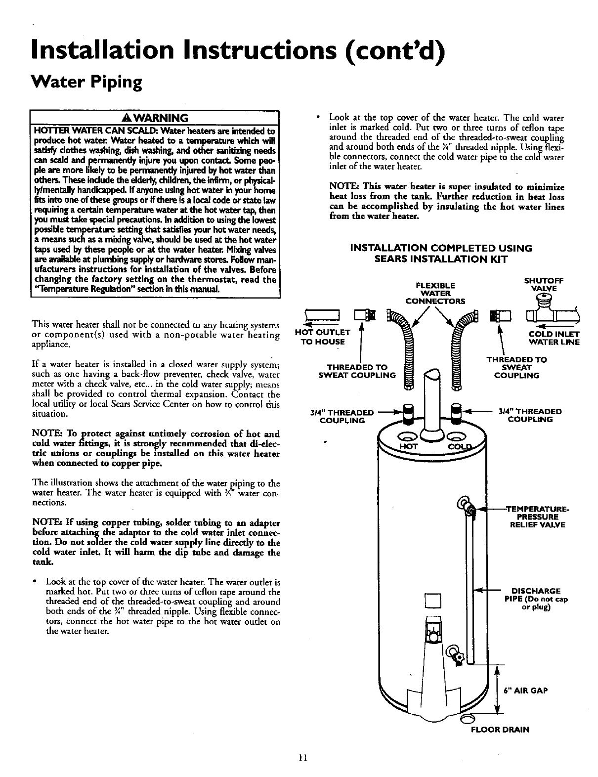
Look at the top cover of the water heater. The water outlet is
marked hot. Put two or three turns of teflon tape around the
threaded end of the threaded-to-sweat coupling and around
both ends of the _A threaded nipple. Using flexible connec-
tors, connect the hot water pipe to the hot water oudet on
the water heater.
•Look at the top cover of the water heater. The cold water
inlet is markedcold. Put two or three turns of teflon tape
around the threaded end of the threaded-to-sweat coupling
and around both ends of the _A threaded nipple. Using flexi-
ble connectors, connect the cold water pipe to the coldwater
inlet of the water heater.
NOTF_ This water heater is super insulated to minimize
heat loss from the tank. Further reduction in heat loss
can be accomplished by insulating the hot water lines
from the water heater.
HOT OUTLET
TO HOUSE
INSTALLATION COMPLETED USING
SEARS INSTALLATION KIT
SHUTOFF
FLEXIBLE VALVE
WATER [_
CONNECTORS ig3
COLD INLET
WATER LINE
THREADED TO
THREADED TO SWEAT
SWEAT COUPLING[_ COUPLING
3/4" THREADED _]I _i_ _1- 314"THREADED
COUPLING _COUPLING
--TEMPERATURE-
PRESSURE
RELIEF VALVE
-- DISCHARGE
]PIPE (Do not cap
or plug)
6" AIR GAP
FLOOR DRAIN
11
Installation Instructions (cont'd)
Temperature-Pressure Relief Valve
AWARNING
At the time of manufacturethis water heater wasprovided
with a combinationtemperature-pressuresrelief valvecerti-
fied by anationallyrecognizedtestinglaboratory teat main-
tainsp.eriodlcinspectionof productionof listedequipmentor
matemls, as meeting the requirements for ReliefValvesand
Automatic Gas Shutoff Devices for Hot Water Supply
Systems,and the latest edition of ANSI Z21.22 andthe cede
requirements of ASME. If replaced, the valve must meet the
requirements of localcedes,but not lessthan a combination
temperature and pressurerelief valve certified as meeting i
the requirements for Relief Valves and Automatic Gas
ShutoffDevicesfor Hot Water SupplySystems,ANSI Z21.22
by a nationallyrecognized testing laboratorythat maintains
periodic inspection of production of listed equipment or
materials.
The valvemust be markedwith a maximum set pressurenot
to exceed the marked hydrostaticworking pressureof the
water heater (150 Ibs.lsq.in.) and a dischargecapacitynot
lessthan the water heater inputrate asshownonthe model
rating plate. (Electric heaters-watts dividedby 1000x 3415
equalBTU/Hr. rate.)
Yourlocaljurisdictionalauthority,while mandatingthe useof
a temperature-pressure relief valve €omplyin.gwith ANSI
Z21.22 and ASME, may require a valve model d_fferentfrom
the onefurnishedwith the water heater.
Compliancewith suchlocal requirements must be satisfied
bythe installeror enduserof the water heaterwith a locally
prescribedtemperature-pressurerelief valve installedin the
designatedopeninginthe water heaterm placeof the facto.
ry furnishedvalve.
For safeoperationof the water heater,the relief valvemust
not be removed from it'sdesignatedopeningor plugged.
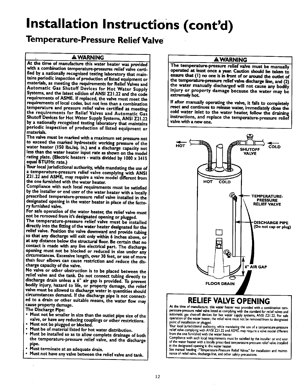
The temperature.pressure relief valve must be installed
directlyinto the fittingof the water heaterdesignatedfor the
relief valve.Position the valve downwardand providetubing
sothat any dischargewill exit only within6 inchesabove,or
at any distancebelowthe structural floor.Be certain that no
contactis made with any live electricalpart. The discharge
openingmust not be blockedor reduced in size under any
circumstances.Excessivelength, over 30feet, or useof more
thah four elbowscan causerestriction and reduce the dis-
chargecapacityof the valve.
No valve or other obstruction is to be placed betweenthe
relief valve and the tank. Do not connecttubing directlyto
dischargedrain unlessa 6" air gap is provided. To prevent
bodily injury, hazardto life, or property damage, the relief
valvemust be allowed to dischargewater inquantitiesshould
circumstancesdemand.If the dischargepipe is not connect-
ed to a drain or other suitablemeans,the water flow may
I causepropertydamage.
The DischargePipe:
Mustnot be smallerin sizethan the outlet pipesizeof the
valve,or haveanyreducing couplingsor other restrictions.
Mustnot be pluggedor blocked.
Mustbe of materiallistedfor hot water distribution.
Must be installedso as to allow completedrainageof both
the temperature-pressurerelief valve, and the discharge
pipe.
Mustterminate at an adequatedrain.
Mustnot haveanyvalvebetweenthe relief valveand tank.
AWARNING
The tomperature-pressure relief valve must be manually
I operated at least once aye_ Caution shouldbe taken to
ensureth_ (I) no one _sin fvent of er _md the outlet of
the temperature-pressurereliefvalvedischargeline,and (2)
the water manually dischargedwill not causeany bodily
injury or property damage because the water may be
extremelyhot,
If after manually operatingthe valve, it failsto completely
reset and continuesto releasewater, immediatelyclosethe
cold water inlet to the water heater, follow the draining
instructions,and replace the temperature-pressure relief
valvewitha newone.
HOT SHUTOFF
VALVE
COLD
IHOT COLD I
PRESSURE
RELIEF VALVE
[]
-DISCHARGE PIPE
(Do not cap or plug)
6" AIR GAP
FLOOR DRAIN
RELIEFVALVEOPENING
At thetimeof m_acture, thiswaterheaterwasprovidedvi_ha com_maUontem-
perature-pressurereliefvalvelistedascomplyingwiththestandardfor reliefvalvesand
automaticgasshut-offdevicesfor hot watersupplysystems,ANSI Z21.22.For safe
op_ationof the waterheater,the _i_ valvemustnot beremove_|tomi_ designate_
pointof installationor plngged.
Yourlocaljurisdictionalauthori_,,whilemandatingthe useof a[emperature-pressure
reL_ valvecor_yi% _i_ ANSiZ2t .7.2andAS_E,r_ayr_ire avalvemodeldifferer_
froththe onefurnishedwichthe waterheater.
Compliancewithsuchlocalrequirementsmustbesatisfiedbythe installerorenduser
of thewa_erheaterw_ aIoc_gyprescribedtempera_re-pressu_ere_f wive ins_alfed
inthedesignatedopeninginthewaterheate_
Seemanualheading."Temperature#ressureReliefValves"forinstallationandmainte-
12
Installation Instructions (cont'd)
Filling the Water Heater
&CAUTION I
Never usethiswater heater unlessit mscompletelyfilledw_l
water.Topreventdamageto the tank, the tank mustbe filledI
with water. Water must flow from the hot water faucet I
I beforetorn ng ON' gasto the water heater.
To fill the water heater with water:
Close the water heater drain valve by turning the handle to
the right (clockwise). The drain valve is on the lower front of
the water heater.
Open the cold water supply valve to the water heater.
NOTE: The cold water supply valve must be left open
when the water heater is in use.
To insure complete filling of the tank, allow air to exit by
opening the nearest hot water faucet. Allow water to run
until a constant flow is obtained. This will let air out of the
water heater and the piping.
• Check all new water piping for leaks. Repair as needed.
Venting
_WARNING
VENT DAMPERS- Any vent damper,whether it is operated
thermallyor otherwisemustbe removedif itsuseinhibitsprop-
er drafting of thewater heator,
Thermally Operated Vent Dampers:Gas-firedwater heaters
havingthermal efEciencyineacessof 80%mayproducea rela-
lowfluegastemperature.Suchtemperaturesmaynotbe
high enough to properly open thermally operated vent
dampen. Thiswouldcausespillageof fluegasesandmaycause
carbonmonoxidepoisoning.
dampersmustbearevidenceofcertiEcntionascomplying
with the latest edition of American National StandardANSI
Z21.68 (ANSI 7.21.66& 67, respectively,coverelectricallyand
mechanicallyactuatedventdampers);Beforeinstallationof any
vent damper,consultyourlocalSea_ ServiceCenter orthe gas
utilityforfurtherinformation.
AWARNING
To insureproper venting of this gas-firedwater heater, the
correctvent pipediameter mustbe utilized.Anyadditionsor
deletions of other gasappliancesona common vent with this
water heater mayadverselyaffectthe operationof the water
heater,Consultthe localSearsServiceCenter or gasutilityif
anysuchchangesare planned.
For proper venting in certain installations, a larger diameter vent
pipe may be necessary. Due to great variances in installations,
unforeseeable by the manufacturer of the water heater, you must
consult your gas company to aid you in determining the proper
venting for your water heater from the vent tables in the latest
edition of the National Fuel Gas Code ANSI Z223.1, also
referred to as NFPA 54.
Check the venting system for signs of obstruction or deterioration
and replace if needed.
The combustion and ventilation air flow must not be obstructed.
AWARNING . I
Obstructed or deteri,o_ted ventsystemsmaypresentasenous
healthrisk or asphyxiation.
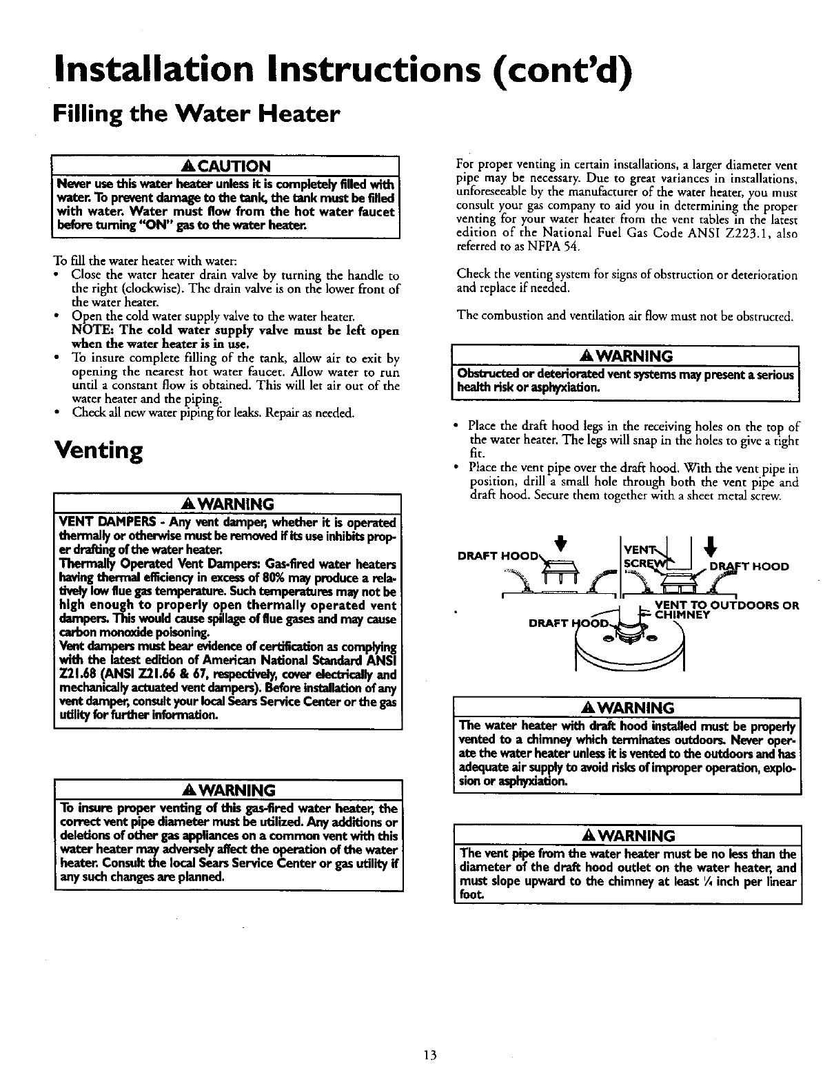
•Place the draft hood legs in the receiving holes on the top of
the water heater. The legs will snap in the holes to give atight
fit.
• Place the vent pipe over the draft hood. With the vent pipe in
position, drill a small hole through both the vent pipe and
draft hood. Secure them together with a sheet metal screw.
DRAFT HOOD _VENT_L t
,"_ _ "_I_SCRF'LW_--J DRAFT HOOD
JLVENT TO OUTDOORS OR
_CHIMNEY
DRAFT
A WARNING I
The water heaterwith draft hoed installedmust be properlyI
ventedto a chimneywhich terminates outdoors. Never oper-
ate the water heaterunlessit isventedto the outdoorsandhasI
adequateairsupplyto avoidrisksof improperoperation, explo-
son or asplrtxiadon.
AWARNING ]
The vent pipefromthrust be no lessthan the |
diameter of the draft hoodoutlet on the water heater, and|
must slopeupwardto the chimneyat least ¼inch per linear|
foot /
13
Installation Instructions (cont'd)
Installation Checklist
BEFORE LIGHTING THE PILOT:
•Check the gas lines for leaks.
a. Use a soapy water solution. DO NOT test for gas leaks
usinga match or open flame.
b. Brush the soapy water solution on all gas pipes, joints and
fittings.
c. Check for bubbling soap. This means you have a leak.
Turn "OFF" gas andmake the necessary repairs.
d. Recheck for leaks.
e. Riuse off soapy solution and wipe dry.
•Is the new temperature-pressure reliefvalve properly installed
and piped to an adequate dram. See Temperature-Pressure
Relief Valve" section.
•Are the cold and hot water lines connected to the water
heater correctly? See "Water Piping" instructions in the
"Installation Instructions" section,
• Is the water heater completely filled with water. See Fdlmg
instructions in the "Installation Instructions" section.
• Will a water leak damage anything? See the "Facts to
Consider About the Location" section.
• ls there proper clearance between the water heater and any-
thing that might catch fire? See the "Facts to Consider About
the Location" section.
• Do you have adequate ventilation so that the water heater
will operate properly? See Combustion Air and Ventilation
in the Installation Instructions section.
•Is the draft hood vent piping properly secur,e,d.See Venung
instructions in the 'Installation Instructions sect'on•
•Is there proper clearance between the vent pipe and anything
that might catch on fir!! See Venting instructions in the
"Installation Instructions section.
•Is the vent pipe properly,sloped and does the vent terminate
outdoors? See "Venting instructions in the Installation
Instructions section.
•Do you need to call your gas company to check the gas pipe
and its hookup?" section•
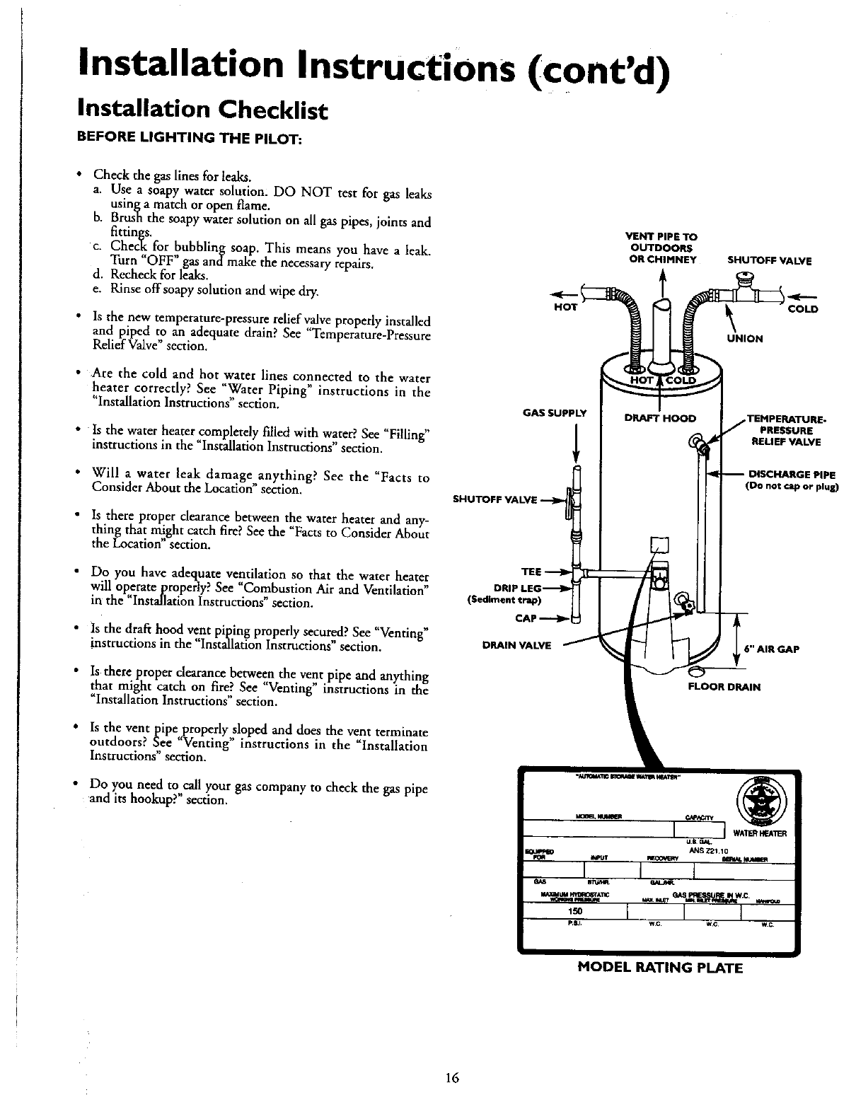
._-.(
HOT
VENT PIPE TO
OUTDOORS
OR CHIMNEY
tSHUTOFF VALVE
COLD
UNION
GAS SUPPLY
SHUTOFF VALVE
(SedimDRnI
DRAIN VALVE
DRAFT HOOD TEMPERATURE-
PRESSURE
RELIEF VALVE
DISCHARGE PIPE
not cap or plug)
"AIR GAP
IN
"_$_MAI_ _WAllU K_AlSq"
€_1S _IAD
:- I I I
MODEL RATING PLATE
16
Operating Instructions
Lighting
_WARNING
BEFORE LIGHTING [PROPANE (L.P.)GAS WATER
HEATE.I.1._.:Propane(L.R) gasisheavierthan air.Shouldthere
be aleak m the system,the gaswill settle near the ground,
Basements,crawl spaces,skirted areasunder mobile homes
(evenwhenventilated),desetsandareasbeiewgroundlevelwill
serve as pockets for the accumulation of this gas. Before
attempting to lightor relightthe water heaterspilotor tuming
ona nearby electricallightswitch,be absolutelysurethereis no
accumulatedgasinthe are_ Searchforodorofgasbymiffing at
groundlevelin the vicinityof the appl_nce.If odorisdetected,
followstepsindicatedat "For YourSafety"onthe coverpageof
this manualthen leavethepremise_
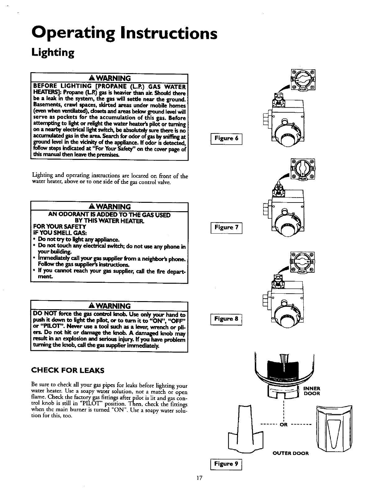
Lighting and operating instructions are located on front of the
water heater, above or to one side of the gas control valve.
AWARNING
AN ODORANT IS ADDED TO THE GAS USED
BY THIS WATER HEATER.
FOR YOUR SAFETY
IF YOU SMELLGAS:
Do not try to lightanyappliance.
Do not touch anyelectricalswitch;do not useanyphonein
your building.
Immediatelycallyour gassupplierfrom a neighbors phone.
Followthe gassuppliersinstruction_
If you cannot reach your gas supplier,call the Ere depart.
men_
AWARNING
DO NOT forcethe gasconUol knob.Use onlyyour hand to
i_s_,hit clownto lightthe pilot,or to turn it to "ON" '_FF"
or PILOT". Never usea tool suchas alever,w_nch or pli-
erL Do not hit or damagethe Imob. A damagedImob may
resultin an explosionandseriousinjury.If you haveproblem
turningthe knob,callthe gassupplier immediately.
CHECK FOR LEAKS
Be sure to check all your gas pipes for leaks before lighting your
water heater. Use a soapy water solution, not a match or open
flame. Check the factory gas,,fittingsafter pilot is lit and gas con-
trol knob is still in PILOT pos!tion,. Then, check the fittings
when the main burner is turned ON . Use a soapy water solu-
tion for this, too.
IFigure 6 I
Figure 8-7
[Figure9
17
OR
OUTER DOOR
Service and Adjustment
Tank (Sediment) Cleaning
Sediment build-up on the tank bottom may create varying
amounts of noise, and if left in the tank will cause premature
tank failure. In some water areas, you may not be able to drain
all sediment deposits by simply draining the tank. In these cases
Mug Erad (part no. 23600) car* be used to help remove the sedi-
ment deposits. This may be ordered from the Sears Service
Center. For ordering, refer to the "Parts Order List section.
AWARNING . ]
Soot build-up indicatesaproblem that requirescorrection
beforefurther use.Turn"OFF" gasto water heaterand leavel
"OFF" until repairs are made,.becausefailureto correct the|
causeof the sootingcanresult m a Ere or explosioncausing/
DEATH,SERIOUSBODILYINJUR_,OR PROPERTYDAMAGE.
Venting System Inspection
At least once a year avisual inspection should be made of the
venting system. You should look for:
Obstructions which could cause improper venting. The com-
bustion and ventilation air flow must not be obstructed.
Damage or deterioration which could cause improper venting
or leakage of combustion products.
Rusted flakes around top of water heater.
AWARNING
i
IChemical vapor corrosionof the flue and vent systemmay
occur if air for combustioncontainscertainchemicalvapors.
Spray can propellants, cleaningsolvents,refrigerator and air
conditionerrefrigerants,swimmingpoolchemicals,calcium
and sodiumchloride,waxes,bleach,and processchemicalsare
typicalcompoundswhichare potentiallycorrosive.
AWARNING
Obstructedor deterioratedvent systemsmaypresenta serious
health risk or asphyxiation.
.AWARNING I
Be sure the vent piping is properly connected to prevent
escape of dangerousflue gasseswhich could causedeadly
asphyxiation. I
AWARNING
If after inspectionof the vent systemyou found sootingor I
deterioration,somethingiswrong.Callthe load gasutilityto I
correctthe problem and dean or replacethe tiueand venting
beforeresumngoperationof the water heater.
Burner Inspection
Burner Cleaning
In the event your burner needs cleaning, use the following
instructions:
If inspection of the burner shows_cleaning is required, turn
the gas control knob clockwise (/" "_) to the "OFF" position,
depressing slightly.
NOTE: The knob cannot be turned from "PILOT" to "OFF"
unless knob is depressed slightly. DO NOT FORCE.
Loose deposits on or around the burner can be removed by care-
fillly using the hose of a vacuum cleaner inserted through the
access door of the water heater. If the burner needs to be removed
for additional cleaning, call the Sears Service Center to remove
and clean the burner and correct the problem that required the
burner to be cleaned.
• AWARNING
Do not usethisapplianceif anypart ofit hasbeenunderwater
Immediately call a SearsServiceTechnicianto inspect the
Iappliance and to replace the gascontrol or any part of the
burnersystemwhich hasbeenunderwater,
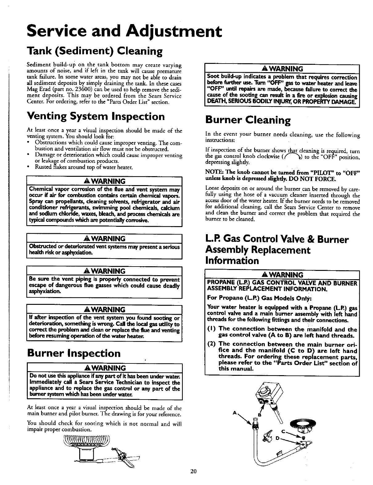
At least once a year avisual inspection should be made of the
main burner and pilot burner. The drawing is for your reference.
You should check for sooting which is not normal and will
impair proper combustion.
L.P.Gas Control Valve & Burner
Assembly Replacement
Information
AWARNING
PROPANE (L.R) GAS CONTROL VALVE AND BURNER
ASSEMBLY REPLACEMENT INFORMATION•
For Propane (L.P.) Gas Models Only:
Your water beater is equipped with a Propane (I-R) gas
control valve and a main burner assemblywith left hand
threads for the following fittingsand their connections.
(I) The connection between the manifold and the
gas control valve (A to B) are left hand threads.
(2) The connection between the main burner ori-
fice and the manifold (C to D) are left hand
threads. For ordering these replacement parts,
please refer to the "Parts Order List" section of
this manual.
20
A\
Service and Adjustment (cont'd)
Draining
The water heater should be drained if being shut down during
freezing temperatures. Also periodic draining and cleaning of
sediment from the tank may be necessary.
Turn the gas control knob to the "OFF" position.
CLOSE the cold water inlet valve to the water heater.
OPEN anearby hot water faucet and leave open to allow for
draining.
Connect ahose to the drain valve and terminate to an ade-
quate drain.
OPEN the water heater drain valve to allow for tank
draining.
NOTE: If the water heater is going to be shut down astd
drained for an extended period, the drain valve should be
left:open with hose connected anow_g water to terminate
to an adequate drain.
Close the drain valve.
•Follow instructions in the "Filling The Water Heater"
section.
Follow the lighting instructions in the "Lighting"section to
restart the water heater.
AWARNING
When checWngthe _, _.._ relief valveoper_
don, _surethat (I) no one is m front of or aroundthe
outlet of the temperature-pressurereliefvalvedischargeline,
and(2) that the water manuallydischargedwill not causeany
propertydamagebecan_ the water maybe extremelyhot.
If after manuallyoperatingthe valve, it failsto completely
reset and continuesto releasewater, immediatelyclosethe
cold water inlet to the water heater, follow the draining
instructions, and replace the temperature-pressure relief
valvewith anewone.
Drain Valve Washer
Replacement
NOTE: For replacement, use a *_2" xxYs*"x_" thick washer
available at your nearest hardware store. For ordering replace-
ment washers, refer to the "Parts Order List3' section.
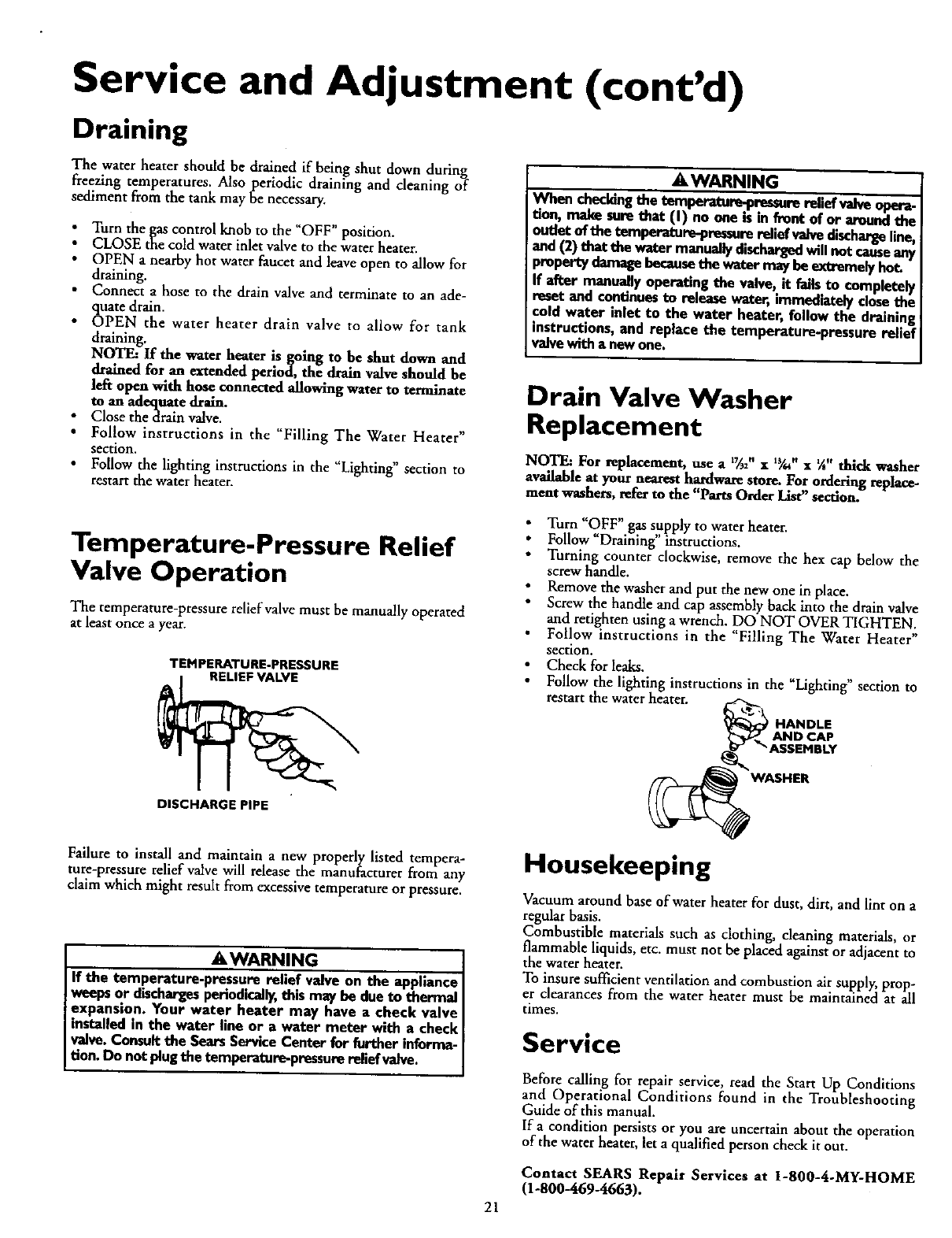
Temperature-Pressure Relief
Valve Operation
The temperature-pressure relief valve must be manually operated
at least once a year.
TEMPERATURE-PRESSURE
RELIEF VALVE
DISCHARGE PIPE
Turn "OFF" gas supply to water heater.
Follow "Draining" instructions.
Turning counter clockwise, remove the hex cap below the
screw handle.
Remove the washer and put die new one in place.
Screw the handle and cap assembly back into the drain valve
and retighten using a wrench. DO NOT OVER TIGHTEN.
Follow instructions in the 'Filling The Water Heater"
section.
Check for leaks.
Follow the lighting instructions in the "Lighting" section to
restart the water heater.
_HANDLE
AND CAP
rT "_ ASSEMBLY
_,WASHER
Failure to install and maintain a new properly listed tempera-
ture-pressure relief valve will release the manufacturer from any
claim which might result from excessive temperature or pressure.
AWARNING
If the temperature-pressure relief valve on the appliance
weepsor dischargesperiodically, thismay be dueto thermal
expansion. Your water heater may have acheck valve
installed in the water line or a water meter with a check
wdve. Consultthe Sears ServiceCenter for further informa-
tion. Do not plugthe temperature-pressurerelief valve.
Housekeeping
Vacuum around base of water heater for dust, dirt, and lint on a
regular basis.
Combustible materials such as clothing, cleaning materials, or
flammable liquids, etc. must not be placed against or adjacent to
the water heater.
To insure sufficient ventilation and combustion air supply, prop-
er clearances from the water heater must be maintained at all
times.
Service
Before calling for repair service, read the Start Up Conditions
and Operational Conditions found in the Troubleshooting
Guide of this manual.
If acondition persists or you are uncertain about the operation
of the water heater, let a qualified person check it out.
Contact SEARS Repair Services at 1-800-4-MY-HOME
(1-800--469-4663).
21
Troubleshooting Guide
Start Up Conditions
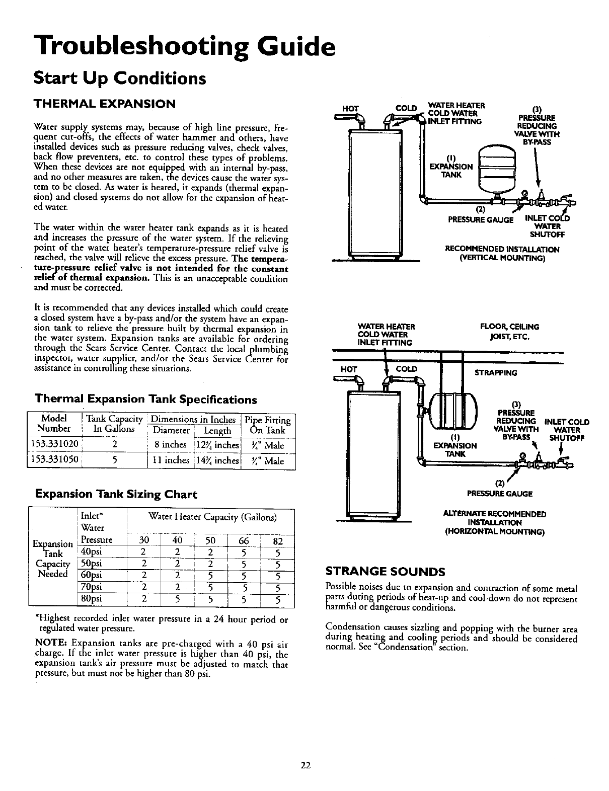
THERMAL EXPANSION
Water supply systems may, because of high line pressure, fre-
quent cut-offs, the effects of water hammer and others, have
installed devices such as pressure reducing valves, check valves,
back flow preventers, etc. to control these types of problems.
When these devices are not equipped with an internal by-pass,
and no other measures are taken, the devices cause the water sys-
tem to be closed. As water is heated, it expands (thermal expan-
sion) and closed systems do not allow for the expansion of heat-
ed water.
The water within the water heater tank expands as it is heated
and increases the pressure of the water system• If the relieving
point of the water heater's temperature-pressure relief valve is
reached, the valve will relieve the excess pressure. The tempera-
ture-pressure relief valve is not intended for the constant
reli_ of thermal expansion. This is an unacceptable condition
and must be corrected.
It is recommended that any devices installed which could create
aclosed system have aby-pass and/or the system have an expan-
sion tank to relieve the pressure built by thermal expansion in
the water system. Expansion tanks are available for ordering
through the Sears Service Center. Contact the local plumbing
inspector, water supplier, and/or the Sears Service Center for
assistance in controlling these situations.
HOT COLD
HOT
WATER HEATER
COLD WATER
INLET Fn-rlNG
WATERHEATER
•COLDWATER (3)
INl.b-rFITnNG PRESSURE
REDUCING
VALVEWITH
BY-PASS
O) !
EXPANSION
TANK
PRESSUREGAUGE WATER
SHUTOFF
RECOMMENDED INSTALLATION
(VERTICAL MOUNTING)
FLOOR,CEILING
joist, ETC.
STRAPPING
Thermal Expansion Tank Specifications
Model ITank Capacity Dimensions in Inches_ Pipe Fitting [
Number In Gallons Diafneter Leng_ II On Tank J
1_0 2 8 in ch_ i!2_in_esi_ _,/}iMale[iil
i53..3-3_50 511 inches il4_inches[ _ Male |
(i)
EXPANSION
(3)
PRESSURE
REDUCING INLETCOLD
VALVEWITH WATER
BY-PASS SHUTOFF
Expansion Tank Sizing Chart
Expansion
Tank
Capacity
Needed
Inlet*
Water
t Pressure
40psi
50psi
60psi
70psi
80psi
Water Heater Capacity (Gallons)
2 --2 ;25 5
22555
2 2 5 5 5
25555
*Highest recorded inlet water pressure in a 24 hour period or
regulated water pressure.
NOTE: Expansion tanks are pre-charged with a 40 psi air
charge. If me !Met water pressure is higher than 40 psi the
expansion tanks air pressure must be adjusted to match that
pressure, but must not be higher than 80 psi.
PRESSUREGAUGE
ALTERNATE RECOMMENDED
INSTALLATION
(HORIZONTAL MOUNTING)
STRANGE SOUNDS
Possible noises due to expansion and contraction of some metal
parts during periods of heat-up and cool-down do not represent
narmful or dangerous conditions.
Condensation causes sizzling and popping with the burner area
during heat!,ng and coolin[_ periods and should be considered
normal. See Condensation section.
22
Troubleshooting Guide (cont'd)
CONDENSATION
Whenever the water heater is filled with cold water, acertain
amount of condensation will form while the burner is on. A
water heater may appear to be leakingwhen in fact the water is
condensation. This usually happens when:
• When a new water heater is filled with cold water for the
first time.
• When gas burns and water vapor isproduced in water
heaters, particularly high efficiency models where flue tem-
peratures are lower.
• When you use large amounts of hot water in a short time
and the refill water is very cold.
Moisture from the products of combustion condense on the
cooler tank surfaces and form drops of water which may fall
onto the burner or other hot surfaces to produce a "sizzling" or
"frying" noise.
Excessive condensation can cause pilot outage due to water run-
ning down the flue tube onto the main burner and putting out
the pilot.
Because of the suddenness and amount of water, condensation
water may be diagnosed as a "tank leak". After the water in the
tank warms up (about 1-2 hours), the condition should disap-
pear.
Do not assume the water heater is leaking until there has been
enough time for the water in the tank to warm up.
An undersized water heater will cause more condensation. The
water heater must be sizedproperly to meet the family's demands
for hot water including dishwashers, washing machines and
shower heads.
Excessive condensation may be noticed during the winter and
early spring months when incoming water temperatures are at
their lowest,
Good venting is essential for a gas fired water heater to operate
properly as well as to carry away products of combustion and
water vapor.
_,WARNING
HOTTER WATER CAN SCALD: Water heaters am intended to
_reduce hot water. Water heated to atemperature which will
satisfy dothes washing,dish washing,and other san_zing needs
can scald and permanently injure you upon contact. Some peo-
ple am more I!k_ly to be permanently injured by hot water than
others. These include the elderly,children,the infirm, or physical-
b/mentally handicapped. If anyoneusinghot water in your home
fits into one of these groupsor if there is a localcede or state law
requiring a certain temperature water at the hot water ta_ then
rou must take specialprecautions. In addition to usingthe lowest
3ossible temperature setting that satisfiesyour hot water needs,
smeans such as a mixing valve,should be usedat the hot water
taps used by these people or at the water heater. Mixing valves
am av_lable at plumbing supplyor hardware stores. Follow man.
ufacturers instructions for installation of the valves. Before
changing the factory setting on the thermostat, read the
'erempereture Regulation" sectioninthis manual.
SMOKE/ODOR
It is not uncommon to experience asmall amount of smoke and
odor during the initial start-up. This is due to burning off of oil
from metal parts, and will disappear in ashort while.
Operational Conditions
SMELLY WATER
In each glasslined water heater there is installed at least one
anode rod (see parts section) for corrosion protection of the
tank. Certain water conditions wilt cause a reaction between this
rod and the water. The most common complaint associated with
the anode rod is one of a"rotten egg smell". This odor is derived
from hydrogen sulfide gas dissolved in the water. The smell is
the result of four factors which must all be present for the odor
to develop:
a. a concentration of sulfate in the supply water.
b. little or no dissolved oxygen in the water.
c. a sulfate reducing bacteria within the water heater. (This
harmless bacteria is non-toxic to humans.)
d. an excess of active hydrogen in the tank. This is caused by
the corrosion protective action of the anode.
Smelly water may be eliminated or reduced in some water heater
models by replacing the anode(s) with one of less active material,
and then chlorinating the water heater tank and all hot water
lines. Contact Scars Service for further information concerning
an Anode Replacement Kit #9001453 and this Chlorination
Treatment.
If the smelly water persists after the anode replacement and chlo-
rination treatment, we can only suggest that continuous chlori-
nation and filtering conditioning equipment be considered to
eliminate the water problem.
Do not remove the anode leaving the tank unprotected. By
doing so, all warranty on the water heater tank is voided.
"AIR" IN HOT WATER FAUCETS
A, WARNING
HYDROGEN GAS: Hydrogen gas can be produced in a hot
water system that has not been usedfor a long period of time
(generally two weeks or more). Hydrogen g_ is extremely
flammable and explosive. To prevent the poss|bility of injury
under these conditions, we recommend the hot water faucet
be opened for several minutes at the kitchen sink before any
electrical appliances which am connected to the hot water sys-
tem are used (such as a dishwasher or washing machine). If
hydrogen gas is present, there will probably be an unusual
soundsimilar to air escapingthrough the pipe as the hot water
faucet is opened. There must he no smoking or open flame
near the faucet at the time it isopen.
23
Troubleshooting Guide (cont'd)
Operational Conditions (cont'd)
HIGH TEMPERATURE SHUT OFF SYSTEM
This water heater is equipped with an automatic gas shut offsys-
rem. The high temperature shut off is built into the gas control
valve. This system shuts off the gas supply to the water heater
burners when high water temperatures are present. It is non-
resettable. If the high temperature shut off activates, the gas,con-
trol valve must be replaced. If this were to occur, turn OFF the
entire gas supply to the water heater. Contact the Sears Service
Center.
_,WARNING
Shouldoverheatingoccur or the gassupply fail to shut off,
turn "OFF" the manual gascontre valve to the appliance.
AWARNING
Due to the nature of the typical gas water heater, the
water temperature in certain situations may be hotter
than the thermostat setting.
Short, frequent draws of hot water - especiallywith very
cold incomingwater - can shockthe thermostat into brief
operation resulting in hotter and hotter layers of water
closer to the top of the tank.
Changesin hot water usagepatterns or raising the tem-
pereture differential between the cut-on of the thermo-
stat and the coldwater temperature will usuallyeliminate
the problem.
NOT ENOUGH OR NO HOT WATER
Check the manual gas shut offvalve to be sure it is open.
Check the pilot flame. It may have gone out. All models have
an opening behind the outer door for viewing the pilot.
I " " " " ' ' " ....
fthe pdot ts not bt, follow the Lighting instructions m this
manual or located above the gas control valve on the water
heater to relight the i_ilot. If the water was extremely hot and
is now cold, the high limit safety"temperature shut off may
have put out the burner and pilot. If the high temperature
shut off activates, the gas control valve must be replaced.
Contact the Sears Service Center.
[. The gas control knob must be turned to the "ON"position.
The temperature adjustment dial may be set too low. See the
"Temperature Regulation"section.
•The gas company can check the gas input to see if it is correct.
An underfired water heater will not heat water as quickly.
• Look for leaking or open hot water faucets. Make sure all are
dosed.
• The cold water inlet temperature may be colder during the
winter months. It will take longer to heat the water and seem
like less hot water.
• If you cannot find what is wrong, call the Sears Service
Center.
WATER IS TOO HOT
1. The temperature adjustment dial may be set too high. See the
"Temperature Adiustment" section.
NOTE: A period of time is necessary after an adjustment has
been made for the water temperature mreach the new tem-
perature setting.
2. If lower temperature settings will not lower the water tempera-
ture, call the Sears Service Center.
24
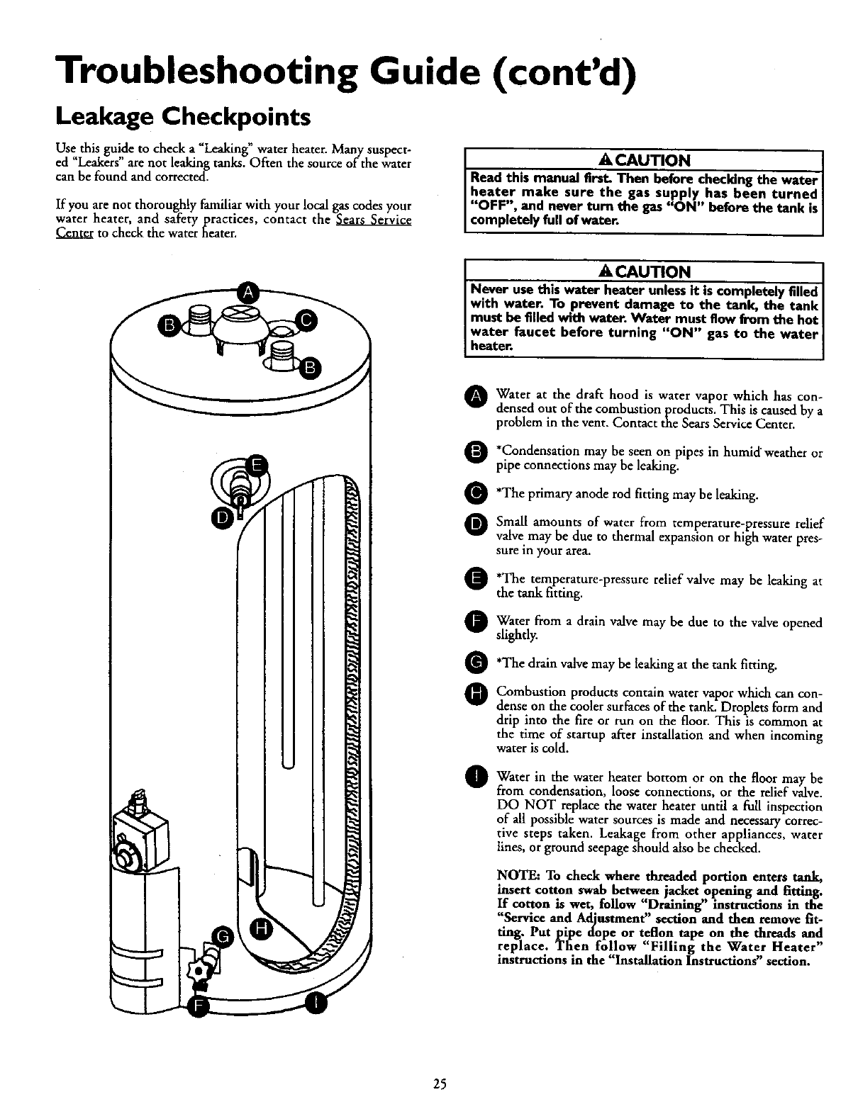
Troubleshooting Guide (cont'd)
Leakage Checkpoints
Use this guide to check a "Leaking" water heater. Many suspect-
ed "Leakers" are not leaking tanks. Often the source of the water
can be found and corrected.
If you are not thoroughly familiar with your local gas codes your
water heater, and safety practices, contact the
to check the water heater.
•ACAUTION
Read this manual first. Then before checking the water
heater make sure the gas supply has been turned
"OFF", and never turn the gas "ON" before the tank is
comp etely fu of water.
ACAUTION I
Never use this water heater unlessit is completely filled
with water. To prevent damage to the tank, the tank
must be filled with water. Water must flow from the hot
I water faucet before turning "ON" gas to the water I
heater•
IWater at the draft hood is water vapor which has con-
densed out of the combustion products, This is caused by a
problem in the vent. Contact the Sears Service Center.
*Condensation be seen on pipes in humid' weather or
may
pipe connections may be leaking.
O'The primary anode rod fitting may be leaking.
Small amounts of water from temperature-pressure relief
valve may be due to thermal expansion or high water pres-
sure in your area.
O'The temperature-pressure may leaking at
relief valve be
the tank fitting.
Water from a drain valve be due to the valve opened
may
slightly.
O'The drain valve be the tank
leaking fitting.
may at
Combustion products contain water vapor which can con-
dense on the cooler surfaces of the tank. Droplets form and
drip into the fire or run on the floor. This is common at
the time of startup after installation and when incoming
water is cold.
Water in the heater bottom the floor be
water or on may
from condensation, loose connections, or the relief valve.
DO NOT replace the water heater until a full inspection
of all possible water sources is made and necessary correc-
tive steps taken. Leakage from other appliances, water
lines, or ground seepage should also be checked.
NOTE: To check where threaded portion enters tank,
insert cotton swab between jacket opening and fitting.
If cotton is wet, follow "Draining" instructions in the
"Service and Adjustment" section and then _mova fit-
ting. Put pipe dope or teflon tape on the threads and
replace. Tfien follow "Filling the Water Heater"
instructions in the "Installation Instructions" section.
25

Notes
26

Notes
27
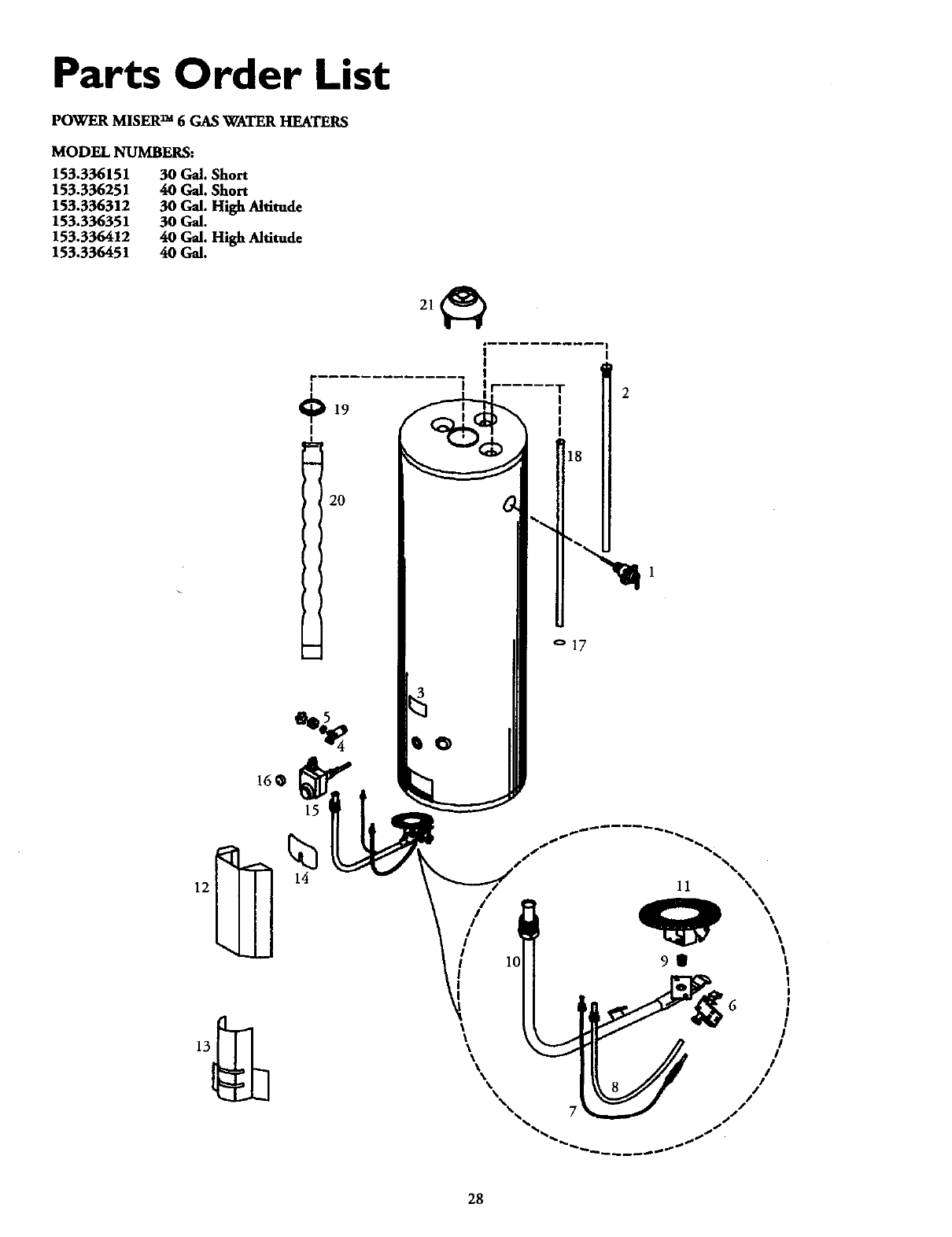
Parts Order List
POWER MISERTM 6GAS WATER HEATERS
MODEL NUMBERS:
153.336151
153.336251
153.336312
153.336351
153.336412
153,336451
30 Gal. Short
40 Gal. Short
30 Gal. High Altitude
30 Gal.
40 Gal. High Altitude
40GaL
O19
20
18
o17
28
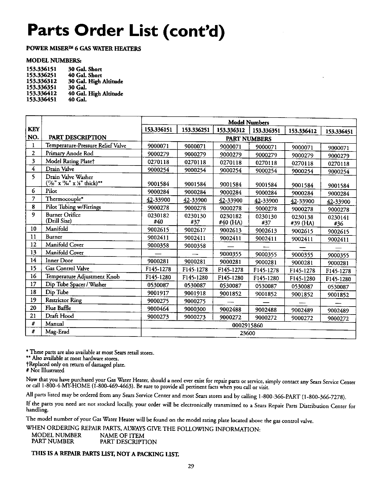
Parts Order List (cont'd)
POWER MISER TM 6 GAS WATER HEATERS
MODEL NUMBERS:
153.336151 30 G_. Short
153.336251 40 Gal. Short
153.336312 30 Gal. High. Altitude
153.336351 30 Gal.
153.336412 40 Gal. High Altitude
153,336451 40 Gal,
KEY
NO. PART DESCRIPTION
1 Temperature-Pressure Relief Valve 9000071
2 Primary Anode Rod 9000279
3 Model Rating Platet 0270118
4 Drain Valve 9000254
5 Drain Valve Washer
(1_2"x '_/d' x _" thick)** 9001584
6 Pilot 9000284
7 Thermocouple* 42-33900
8 Pilot Tubin_ w/Firtings 9000278
9Burner Orifice 0230182
(Drill Size) #40
10 Manifold 9002615
11 Burner 9002411
12 Manifold Cover 9000358
13 Manifold Cover
14 Inner Door 9000281
15 Gas Control Valve F145-1278
16 Temperature Adjustment Knob F145-1280
17 Dip Tube Spacer /Washer 0530087
18
19
20
21
#
#
153.336151 153.336251 153.336412 153.336451
9000071
9000279
0270118
9000254
9001584
9000284
42-33900
9000278
0230130
#37
9002617
9002411
9000358
9000281
F145-1278
F145-1280
0530087
Model Numbers
153.336312 153.336351
PART NUMBERS
9000071 9000071
9000279 9000279
0270118 0270118
9000254 9000254
9001584 9001584
9000284 9000284
42-33900 42-33900
9000278 9000278
0230182 0230130
#40 (HA) #37
9002613 9002613
9002411 9002411
9000355 9000355
9000281 9000281
F145-1278 F145-1278
F145-1280 F145-1280
0530087 0530087
9O00071
9000279
0270118
9000254
9001584
9000284
42-33900
9000278
O230138
#39 (HA)
9002615
9002411
9000355
9000281
F145-1278
F145-1280
0530087
9000071
900O279
0270118
900O254
9001584
9000284
42-339O0
9000278
0230141
#36
9002615
9002411
m
9000355
9000281
F145-1278
F145-1280
0530087
Dip Tube 9001917 9001918 9001852 9001852
Res_ictorRin_ 9000275 9000275 -- --
_ue Baffle 9000464 9000300 9002488 9002488
Draft Hood 9000273 9000273 9000272 9000272
Manual 0002915860
Mag-E_d 23600
9001852
9002489
9000272
9001852
9002489
9000272
***Thesepasts,are also availableat most Sears retail"stores.
Also availableat most hardware stores.
tReplaced only on return of damaged plate.
# Not Illustrated
Now that you have purchased your Gas Water Heater, should aneed ever exist for repair parts or service,simply contact any Sears ServiceCenter
or call 1-800M-MY-HOME (1-800-4694663). Be sure to provide all pertinent facts when you call or visit.
All parts listed may be ordered from any Sears Service Center and most Sears stores and by calling 1-800-366-PART (1-800-366-7278).
If the parts you need are not stocked locally, your order will be electronically transmitted to aSears Repair Parts Distribution Center for
handling.
The model number of your Gas Water Heater will be found on the model rating plate located above the gas control valve.
WHEN ORDERING REPAIRPARTS, ALWAYSGIVE THE FOLLOWING INFORMATION:
MODEL NUMBER NAME OF ITEM
PART NUMBER PART DESCRIPTION
THIS IS A REPAIR PARTS LIST, NOT APACKING LIST.
29
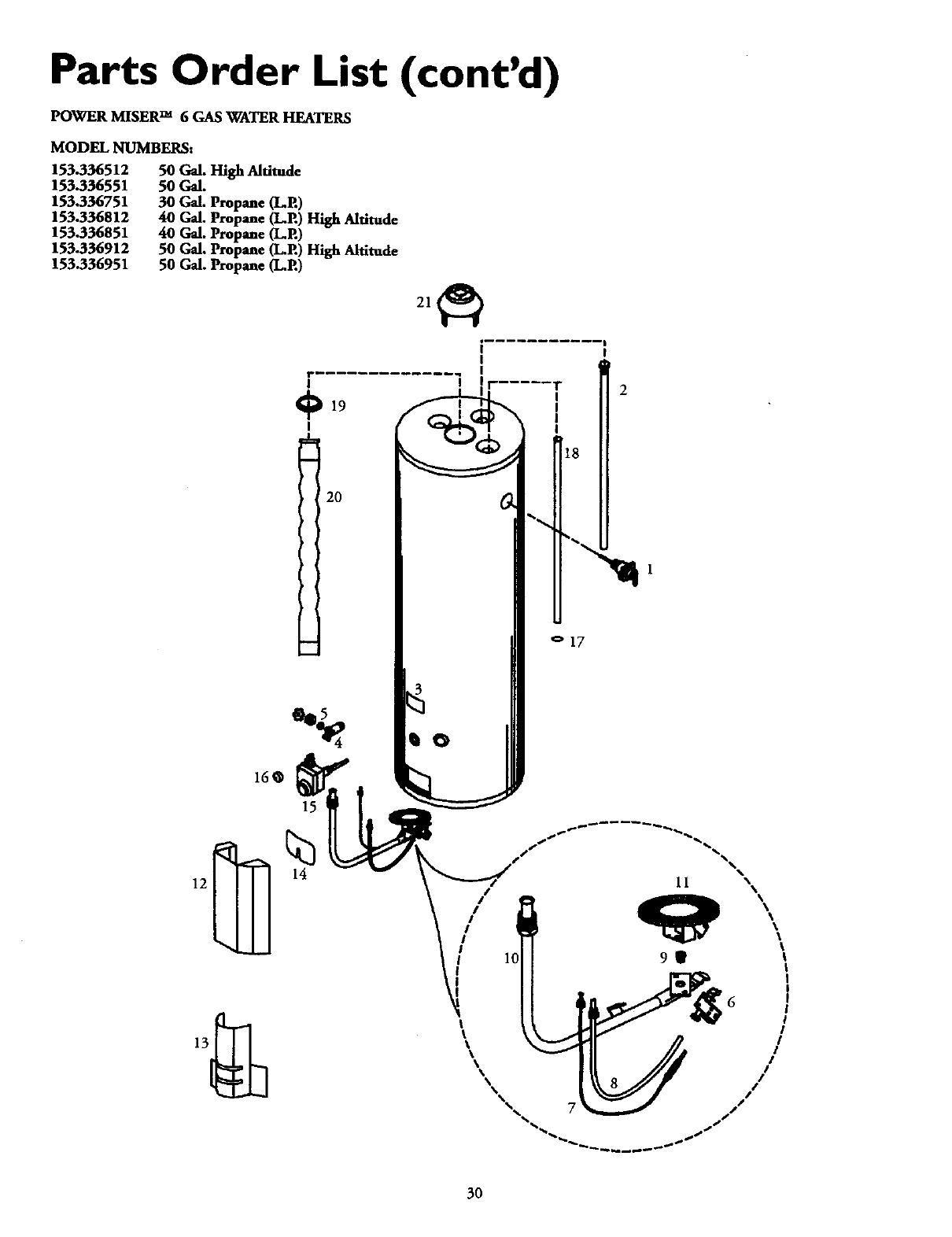
Parts Order List (cont'd)
POWER MISER TM 6GAS WATER HEATERS
MODEL NUMBERS:
153.336512
153.336551
153.336751
153.336812
153.336851
153.336912
153.336951
50 Gal. High Altitude
5O Gal.
30 Gal. Propane (L.P.)
40 Gal. Propane (L.P.) High Altitude
40 Gal. Propane (LP.)
50 Gal. Propane (L.P.) Higfi Altitude
50 Gal. Propane (L.P.)
160
_19
I
2O
15
I
I
IIF .....
0
o17
14
2
*%
11
3O
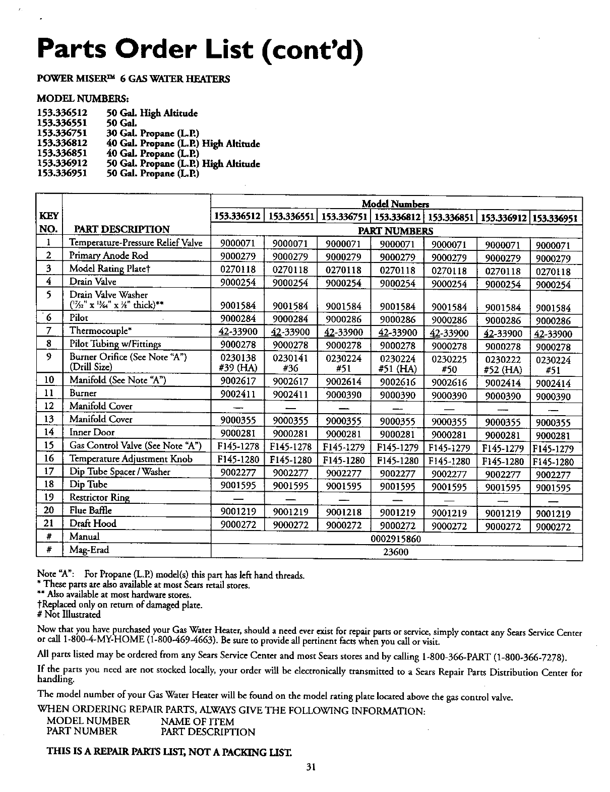
Parts Order List (cont'd)
POWER MISERTM 6GAS WATER HEATERS
MODEL NUMBERS:
153.336512
153.336551
153.336751
153.336812
153.336851
153.336912
153.336951
50 Gal. High Altitude
50 Gal.
30 Gal. Propane (LP.)
40 Gal. Propane (LP.) High Altitude
40 Gal. Propane (LP.)
50 Gal. Propane (L.P.) High Altitude
50 Gal. Propane (LP.)
KEY
NO. PART DESCRIPTION
1Temperature-PressureRelief Valve
2 Primary Anode Rod
3Model Ratin_ Platet
4Drain Valve
5Drain Valve Washer
('_2" x 'Y." x _" thick)**
6Pilot
7Tbermocouple*
8Pilot Tubing w/Fittings
9Burner Orifice (See Note "A')
(Drill Size)
10 Manifold (See Note _A")
11 Burner
12 Manifold Cover
13 Manifold Cover
14 Inner Door
15 Gas Control Valve (See Note _A')
16 Temperature Adjustment Knob
17 Dip Tube Spacer /Washer
18
19
20
21
#
#
Model Numbers
153.336512 153.336551 153.336751 153.336812 153.336851 153.336912 153.336951
PART NUMBERS
9000071
9000279
0270118
9000254
9001584
9O00284
42-33900
9000278
0230138
#39 (HA)
9002617
9002411
90OO355
9000281
F145-1278
F145-1280
9002277
9000071
9000279
0270118
9OOO254
9001584
9000284
42-33900
9000278
0230141
#36
9002617
9002411
9OOO355
9000281
F145-1278
F145-1280
9002277
9000071
9000279
0270118
9000254
9001584
9000286
42-33900
9000278
0230224
#51
9002614
9000390
9000355
9000281
F145-1279
F145-1280
9002277
9000071 9000071
9000279 9000279
0270118 0270118
9000254 9000254
9001584 9001584
9000286 9000286
42-33900 42-33900
9000278 9000278
0230224 0230225
#51 (HA) #50
9002616 9002616
9000390 9000390
9000355 9000355
9000281 9000281
F145-1279 F145-1279
F145-1280 F145-1280
9002277 9002277
9000071
9000279
0270118
9000254
9001584
9000286
42-339OO
9000278
0230222
#52(HA)
9002414
9000390
9OOO355
9000281
F145-1279
F145-1280
9002277
9OOOO71
9000279
0270118
9000254
9001584
9000286
42-33900
9000278
0230224
#51
9002414
9000390
9OOO355
9000281
F145-1279
F145-1280
9002277
Dip Tube
RestrictorRing
Flue Baffle
Draft Hood
Manual
Mag-Erad
90O1595
9001219
9000272
9001595
9001219
9000272
9001595
9001218
9000272
9001595
9001219
9000272
0002915860
23600
9001595
9001219
9000272
9001595
9001219
9000272
9001595
9001219
9000272
Note "A': For Propane (L.E) model(s) this part has left hand threads.
*These parts are also availableat most Sears retail stores.
**Also availableat most hardware stores.
tReplaeed only on return of damaged plate.
# Not Illustrated
Now that you have purchased your Gas Water Heater, should aneed ever exist for repair parts or service, simply contact any Sears ServiceCenter
or call 1-800-4-MY-HOME (1-800-469-4663). Be sure to provide all pertinent factswhen you call or visit.
All parts listed may be ordered from any Sears Service Center and most Sears stores and by calling 1-800-366-PART (1-800-366-7278).
If the parts you need are not stocked locally, your order will be electtonically transmitted to a Sears Repair Parts Distribution Center for
handling.
The model number of your Gas Water Heater will be found on the model rating plate located above the gas control valve.
WHEN ORDERING REPAIR PARTS,ALWAYSGIVE THE FOLLOWING INFORMATION:
MODEL NUMBER NAME OF ITEM
PART NUMBER PART DESCRIPTION
THIS IS A REPAIR PARTS LIST, NOT APACKING LIST.
31
Warranty
About YourWarranty
THE PRICE OF YOUR WATERHEATER DOES NOT INCLUDE
A FREE CHECKUP SERVICE CALL. On Water Heater Installations
ArrangedBy Sears,Searswarrants theinstallation.
ON INSTALLATIONS NOT MADE BY SEARSAUTHORIZED
CONTRACTORS:
1.YourSearswarrantyappliesto the product only.
2. Searsdoesnot warrant the installation.
3. A charge will be made on servicecalls due to poor or incomplete
installation.Theseinclude:
a. Adjusting thermostat.
b. Lightingpilot.
c. Leaksin pipesorfittings.
d. Improperventing
e. Condensation
This manual is in non-technical language.It may help you ,avoidthe
cost of a needlessservice call. Many service calls really arent needed.
Suchas when:
1.The gasis turned _OFF'.
2.The pilot isout.
3.Agasor water leakisdue to loosepipe or connections.
FULL ONE YEAR WARRANTY ON WATER HEATER
For one year from the date of purchase, when your Sears Kenmore water heater is installed and operated in a single-family residence in
accordance with the instructions in this manual, Sears will:
1. Repair defects in material or workmanship in this water heater, free of charge.
2. Furnish and install a new current model water heater of equal capacity and quality, free of charge, ifa leak occurs in the tank.
LIMITEDWARRANTYON TANKSTHATLEAK
Afterone yearand through 6 yearsfrom the date of purchasefor waterheaters used in a single-familyresidence,ifa leakoccursin the
tank, Searswillfurnish a newcurrent model water heaterof equalcapacityand quality. Youwillbe charged for any installation.
LIMITED WARRANTYON PARTS
After one year and through 6years from the date of purchase, when your Sears Kenmore water heater is used in asingle-family residence
and is installed and operated in accordance with the information in this manual, ifa parr fails due to amaterials or workmanship, Sears
will furnish areplacement free of charge. You will be charged for labor.
If the water heater is subjected to commercial, institutional, industrial or use in residences of two families or more, the above warranty
coverage for tanks that leak is effective for 2 years from the date of purchase and the above parts warranty is effective for 1year from the
date of purchase.
To obtain warranty service, SIMPLY CALL 1-800-4MY-HOME (1-800-469-4663). _Th s warranty appl es only whde this product ism" " ""
use in the United States."
This warrantygivesyou specificlegalrights andyou mayalso haveother rightswhich varyfrom state to state.
SEARS, ROEBUCK AND CO., Dept. 817 WA, HOFFMAN ESTATES, IL 60179
Sears Installation Warranty
In addition to any warranty extended to you on the Sears merchandise
involved, which warranty becomes effective the date the merchandise is
installed should the workmanship of any Sears arranged installation
prove faulty within one year, Sears will, upon notice from you, cause
such faults to be corrected at no additional cost to you. If you want this
heater professionally installed by Sears contact your Sears Salesperson.
They will arrangefor prompt, quality installation.
Sears Installation Policy
All installationlabor arranged bySearsshallbe performed in aneat,
workmanlike manner in accordancewith generallyacceptedtradeprac-
tices.Further,all installationsshallcomplywithalllocallaws,codes
regulationsandordinances.The customershallalsobe protected,dur-
ing installation,by insurance relatingto property damage,Worker's
Compensation and PublicLiability. ....
Ifyou want this waterheater professionallyinstalled bySearscontact
your Salesperson.They willarrangefor prompt, qualityinstallationby
Searsauthorizedcontractors.
Forin-homemajorbrandrepairservice
Call24hoursaday,7 daysaweek
1-800-4-MY-HOME
(1-800-469-4663)
The model number of your water heater is found on the model rating plate on the front of the water heater.
"-" Sears, Roebuck and Co., Hoffman Estates, IL 60179 U.S.A. ooo291s_oi
