Kenmore 15813160 User Manual SEWING MACHINE Manuals And Guides L9080242
KENMORE Mechanical Sewing Manual L9080242 KENMORE Mechanical Sewing Owner's Manual, KENMORE Mechanical Sewing installation guides
User Manual: Kenmore 15813160 15813160 KENMORE KENMORE SEWING MACHINE - Manuals and Guides View the owners manual for your KENMORE KENMORE SEWING MACHINE #15813160. Home:Laundry & Garment Care Parts:Kenmore Parts:Kenmore KENMORE SEWING MACHINE Manual
Open the PDF directly: View PDF ![]() .
.
Page Count: 4
1'58. 1316O
Hi i i,
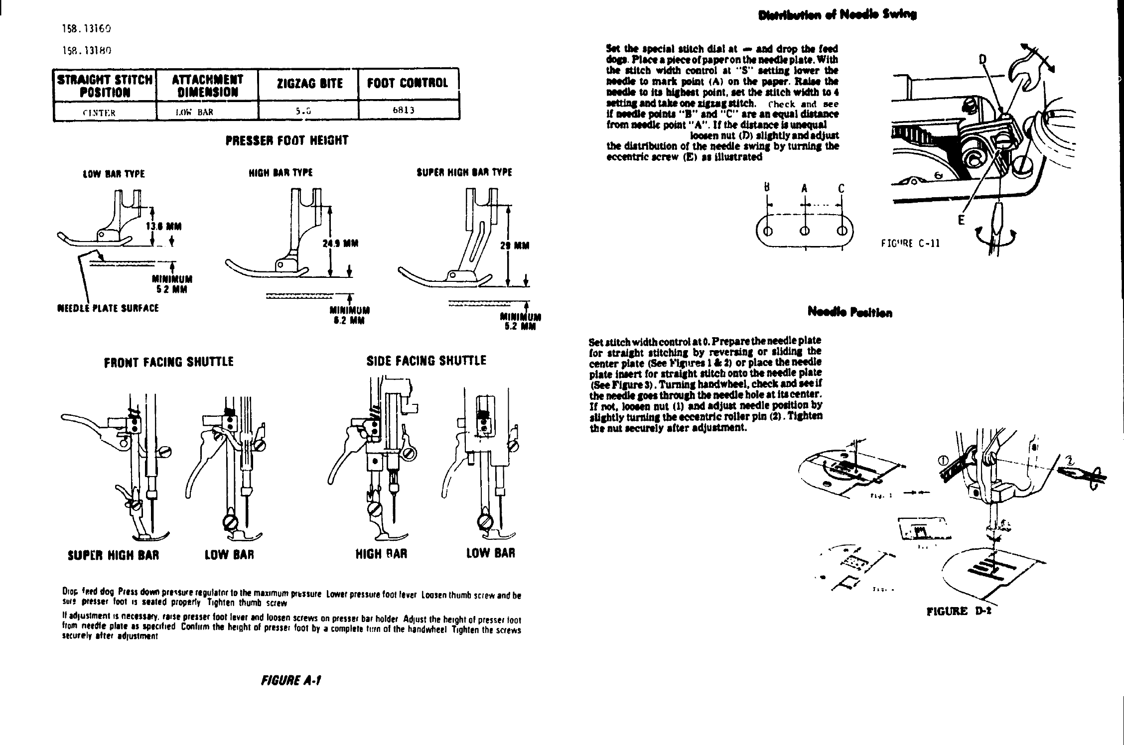
STRAIGHT STITCH ATTACHMENT ZIGZAG BITE FOOT CONTROL
POSITION DIMENSION
r_t.'¢Tf;R I,()Y; BAR 5._ b813
i • ,
PRESSERFOOT HEIGHT
LOWBARTYPE
l_.i MM
MINIMUM
62 MM
NEEDLEPLATESURFACE
HIGH BARTYPE
MINIMUM
8.2 MM
SUPERHIGH OARTYPE
2_MM
i .......
5.2 MM
FRONT FACINGSHUTTLE
SUPER HIGH BAR
SIDE FACING SHUffLE
LOW BAR HIGH OAR LOW BAR
Oropfeed dog Pressdo_ pressureregulaterto the max,mumpressure Lowerpressurefootlaver Loosenthumbscrewand be
sure presser foot ,s seated properly Tzghtenthumb screw
If edlustment ,s necessary,re,as presserfoot lever andloosen screwson presserbar holder Adjustthe betghtof presserfoot
from needle plate as spac,f,ed CtNlflrmthe Ileight of presse, foot by acompletett[rnof the handwheei T,ghtenthe screws
securely after odlustn_ot
FIGUREA.I
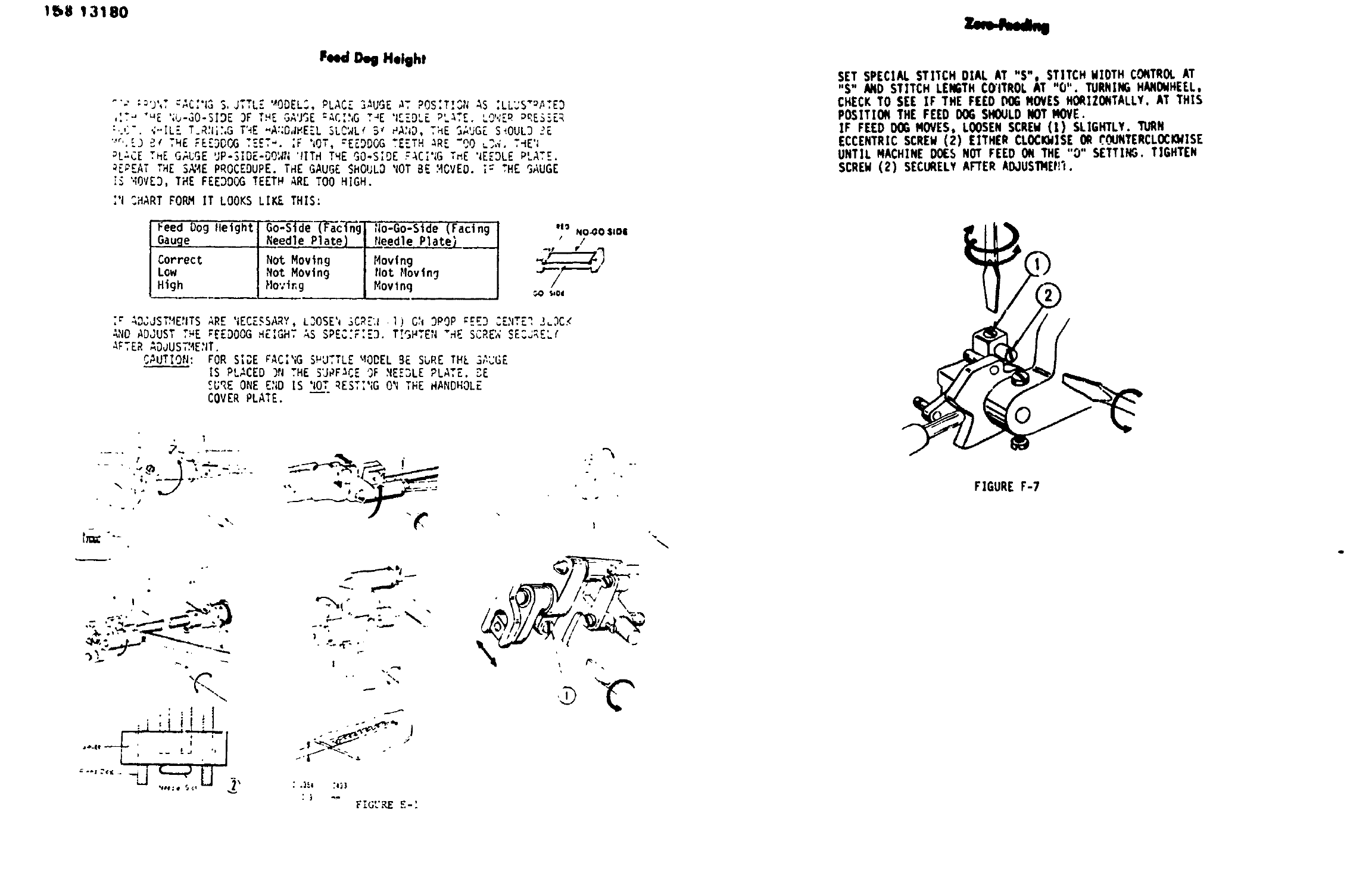
mmlbv,kn aN,edb Sv,
Set the special stitch dial at ,,- and drop the feqM
dogs. Pla_e • piece of paper on the Mndle plate. With
the Iddtch wklth control at "'S" setting lower il_
laecMie to m•rk paint (A) on the paper. _tim
needle to its idghest point, set the stitch width to 4
IJett_Jfldt,ldmoileglsgatlglUtch. ('beck and see
If needle pelnte "B" end "C" am an equal distance
from needle point "A". If the distance Is unequal
Io_;en nut (D) sllolttly andndJuat
the dJat_bution of the needle swing by turnin8 the
occentr/e screw (E) as illustrated
8 A C
I
Set stitch width control •t O.Prepam the needle plate
for straight atttc_n| by reveradn| or slidinll the
center plate (See I_blpU'es 1 & 31 or place the needle
plate insert for straight stitch onto the ne4Mle pla_
(See FiiPu'e 3). Tur'ninll handwheei, check and see if
the needle goes through the needle bole at Its center.
If not, loosen nut (1) and adjust needle poMilon by
sflghtly turnin8 the eccentric miler pin (S). Tighten
the nut securely after •€lJustment.
E
FIGLIKE D..t
1_,8 13180
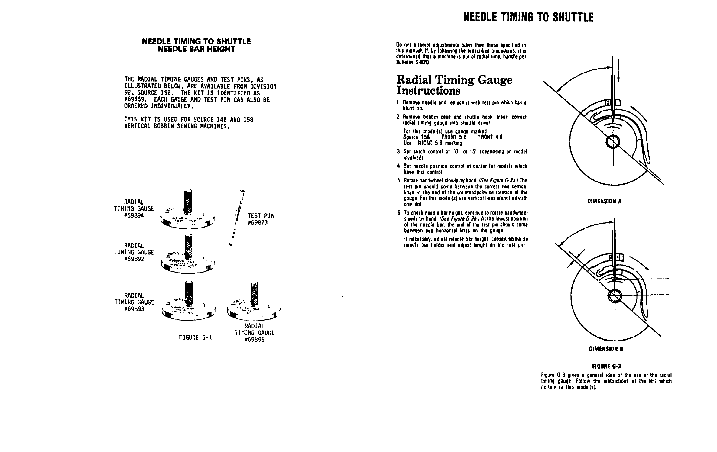
Feed Deg Height
"P ._J',T -C,I.3S,JTTLZ '_0DEL_,PLACE ]HUGE HT ?OS.T.v,;AS .LL.S _,_3
,IT- "uE '_(J-GO-SIDE3F THE ,_-J_E:HC:'_GT_E "IEEDLEPL_TEo '_""_PP_,E_:.ER
:'.'i".','ILET.R'|_:,GT'_E"A::D,JI_E'ZL_LC'_Lf5_ PA'4D,T}IESAUGE S_OUL3 ._Z
'"_'.E]_ THE ,:EEDOCGTE.CT_. ;F '_OT,"EEDDGG TEETH HRE "00 _],V.T_E'_
PL-'CETHE GAI;GE ....... " _....._P-_Dc-uO._,,'IITHTHE S0-SIDE ."_CI';GT_E '_EEOLEP'_'_
_ZPEAT THE S_4E PROCEDUPE. THE GAUGE SHOULD 'lOTBE '4CVED.is THE gAUGE
IS "OVE3, THE FEEDDOG TEETH ARE TOO HIGH.
:'ICHART FORM IT LOOKS LIKE THIS:
Feed Dog lleight Go-Slde (FacT@g, No-Go-Side (Facing
Gauge Needle Plate) Needle Plate)
Correct Not Moving Moving
Low Not Moving Not Movln_
High Moving Movlng
NO-_O liD|
•/
.7--..
;_ AD_JST'4E:ITSARE 'IECZSSARY,LOOSE'_3CRE',_•I) CN 3POP _EE3 CE,_ITE_,J_OC._
AND ADJUST T_E ;EED00G HEIGHT AS SPEC'F:E3. T._H,E,I HE SCRE"_SE=J_ELf
AFTER -DJUS,AE,JT.
CAUTION: FOR SI_,EF'AC,,G _ U,,L. _ODEL BE SvRE THE _,,_G_
IS PLACED ]N THE SURFACE OF REE3LE PLATE. 3E
SI_REONE E';DIS 'IO__T.RESTI'IGON THE HANDHOLE
COVER PLATE.
/
.: *! I
_._._ _ w"_#N "_ " _ _"
}
I
:).- FIG".RE_-'
\
SET SPECIAL STITCH DIAL AT "S", STITCH WIOTH CONTRO!.AT
"S" AND STITCH LENGTHCGITROL AT "O". TURNING MANOMHEEL,
CHECKTO SEE IF THE FEED DO6MOVES HORIZONTALLY. AT THIS
POSITION THE FEED DO6 SHOULDNOT MOVE.
IF FEED O_ MOVES, LOOSENSCREW(1) SLIGHTLY. TURN
ECCENTRIC SCREW(2) EITHER CLOCI_ISE OR rOUNTERCLOCIO_ISE
UNTIL MACHINE DOES NOT FEED ON THE "0" SETTING. TIGHTEN
SCREW(2) SECURELYAFTER ADJUS1)IEt!_.
FIGURE F-7
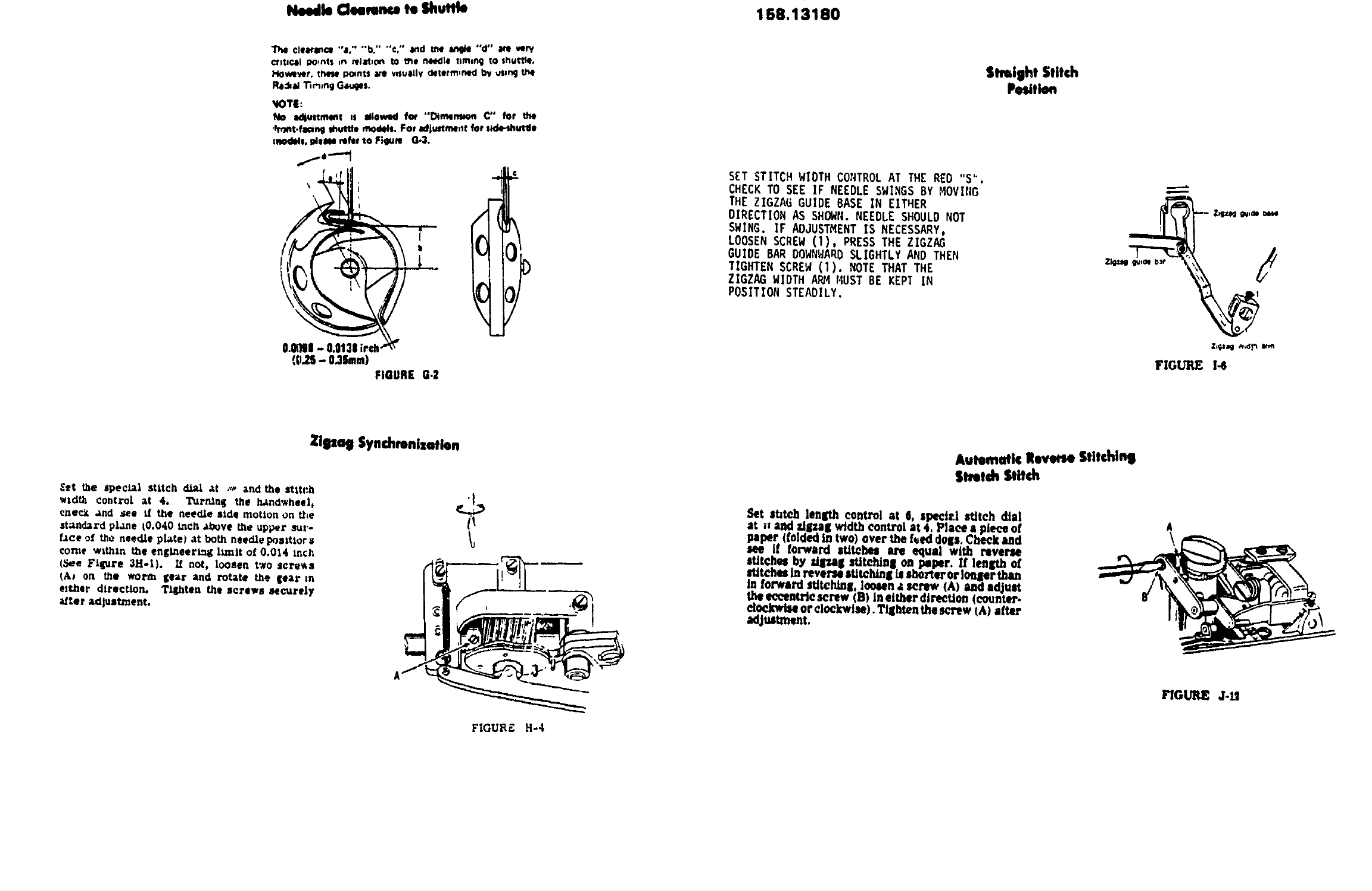
NEEDLE TIMING TO SHUTTLE
NEEDLE BAR HEIGHT
THE RADIAL TIMING GAUGESAND TEST PINS, /1_
ILLUSTRATED BELOW, ARE AVAILABLE FROH DIVISION
92, SOURCE192. THE KIT IS IDENTIFIED AS
#69659. EACH GAUGEAND TEST PIN CAN ALSO BE
ORDEREDINDIVIDUALLY.
THIS KIT IS USED FOR _OURCE 148 AND 158
VERTICAL BOBBIN SEWING MACHINES.
RADIAL
TJ_ING GAUGE
#69894
RADIAL
TIMING GAUGE ..._'.._.,
#69892 1%._...%,,7;¢. "_
RADIAL
TIMING GAUG_
#69_93
TEST PIN
#69873
/
_g
RADIAL
_IHING GAUGE
FIGURE G-t #69895
NEEDLETIMINGTOSHUTTLE
Do net attempt idlvStmlnts other men tflose specifiedin
this manual, if. by fo_lomngthe prescr,bedprocedmos,it LS
determined that o machine is out Ofrod, el time. handleper
Bulletin S-920
Radial Timing Gauge
Instructions
1. Removeneedle end replace ,t w_thtest pmv_ich hase
blunt bp.
2 Remove bobbin case end shuttle hook Insert correct
radial t,mm9 gauge into shuttle dr,ve¢
For this mad€lie) use gauge marked
Source 158 FRONT 58 FRONT 40
Use FflONT 5 8 matkmg
3 Set stitch controlat "0" or "S" (depondmgon model
involved)
4 Set needle poslhoncontrol at centerfor modelswhich
have this control
._ Rotatehsndwhanl slowlyby hand (See F@u,'e_;.3a JThe
test pm should come between the correct two vertical
Ira,as,** the end of the counterclockwiserotohon of the
gouge For this model(s)usevemcal hoes,dentifiedv,,th DIMENSION A
one dot
Tochick needle bar hl,ghL continueto rolntehandwhlel
slowlyby hand fSee hgum G.3#I At the lowestposst,on
of the needle bar. the end of the test pm shouldcome
between two hor,zontalhnes On the gouge
If necessaet,adjust needle bar ha,ght Loosenscrew on
needle bar holder and adjust height on the list pen
OIMENSIONN
FIgURIE 0.3
F_g,JreO 3 gives egeneral _deeof the use of the rad,td
tzmmggauge Follow the tnstlUCtlOnSat the left wh,ch
pertem in this modeKs)
Needle €Icero.ca te Shuttle 158.13180
CIIMI_Ol "a0" "'b." "€," 8nd U_ _e '°d" ire very
cttttc4t points tn _|M_on to _he needle tlmlr_ to shuttle.
H0wlver. these po4ntS ue v,sulllv _torm,ned by _S,ng t/_
Ro4,ad "l_M_ngO_s.
_lOTl:
No acllultment as allow_l fcw "_mem_on C'* for the
•_nt.faang muttle n_€lelo. For adjustmentfor mle-0hutlle
n_kds, pleeN referto Fiqum Q.3.
Zigzag Synchronization
£et tile special stitcli _ :t _- _Lndthe stitch
_tdU_ co_trn_ ;Lt 4. T_rN, nS the _nd'_heel.
cnecx .;Jld see _f the neecUe side motion on t_e
st_d_rd plane t0,040 tncll _,bove the upper sur-
face o( _he needJ.e plate) _t both needle ponitior
come within the enlItheer_l{ tzmit o( 0.014 inch
(_e Flip, re 3H-l). If not, loosen two screws
(A_ on _be worm i_ear _md rotate the 