Kenmore 1581789180 User Manual SEWING MACHINE Manuals And Guides L9090237
KENMORE Mechanical Sewing Manual L9090237 KENMORE Mechanical Sewing Owner's Manual, KENMORE Mechanical Sewing installation guides
User Manual: Kenmore 1581789180 1581789180 KENMORE KENMORE SEWING MACHINE - Manuals and Guides View the owners manual for your KENMORE KENMORE SEWING MACHINE #1581789180. Home:Laundry & Garment Care Parts:Kenmore Parts:Kenmore KENMORE SEWING MACHINE Manual
Open the PDF directly: View PDF ![]() .
.
Page Count: 11
SERVICE MANUAL
model 1789180
II
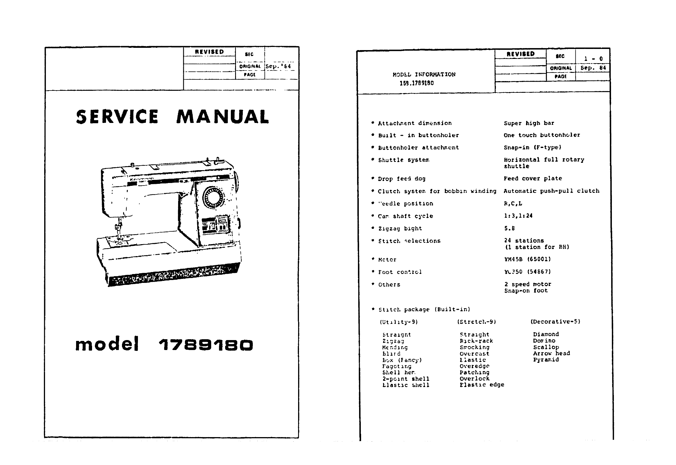
MODLL INFOR_T_[ON
15aJ.1789180
n,v,H. .c
• Attact_,ent dlmens_on
•Built - in buttonholer
•Euttonholer attach_.ent
tShuttle system
•Drop feed dog
•Clutch system for bobbzn winding
•"'eedle positlon
• Cam _haft ¢_cle
•ZzgZag blght
•Stztch _elections
• Meter
• Foot control
"Others
Super high bar
One touch buttonholer
Snap-in (F-type)
Xorizontal full rotary
chu_tle
Feed cover plate
Automatic push-pull clutch
I_,C,L
1:3,1,24
5.8
24 stations
(1 station for BH)
YM45B (65001)
Y4.250 (54867)
2speed motor
Snap-on foot
5tztch package (Built-in)
(Ut_lzty-9) (Stretch-9)
btrazgnt
2_gZag
Mcn_zr,g
51_rd
Box (fancy)
Fagoting
Shell her.
2-p_znt shell
Llastlc shell
Ftrazght
R_ck-rack
Smocking
Overcast
[iastic
Overedge
Patching
Overlock
Elastic edge
(Decorative-5)
Diamond
Do. ino
Scallop
Arrow head
Pyramid
i
I_
NEEDLE BAR HEZGHT
REVILED SIC
Oct. 84 I- 1
+ ommm,L KJy, s4
PAO! l
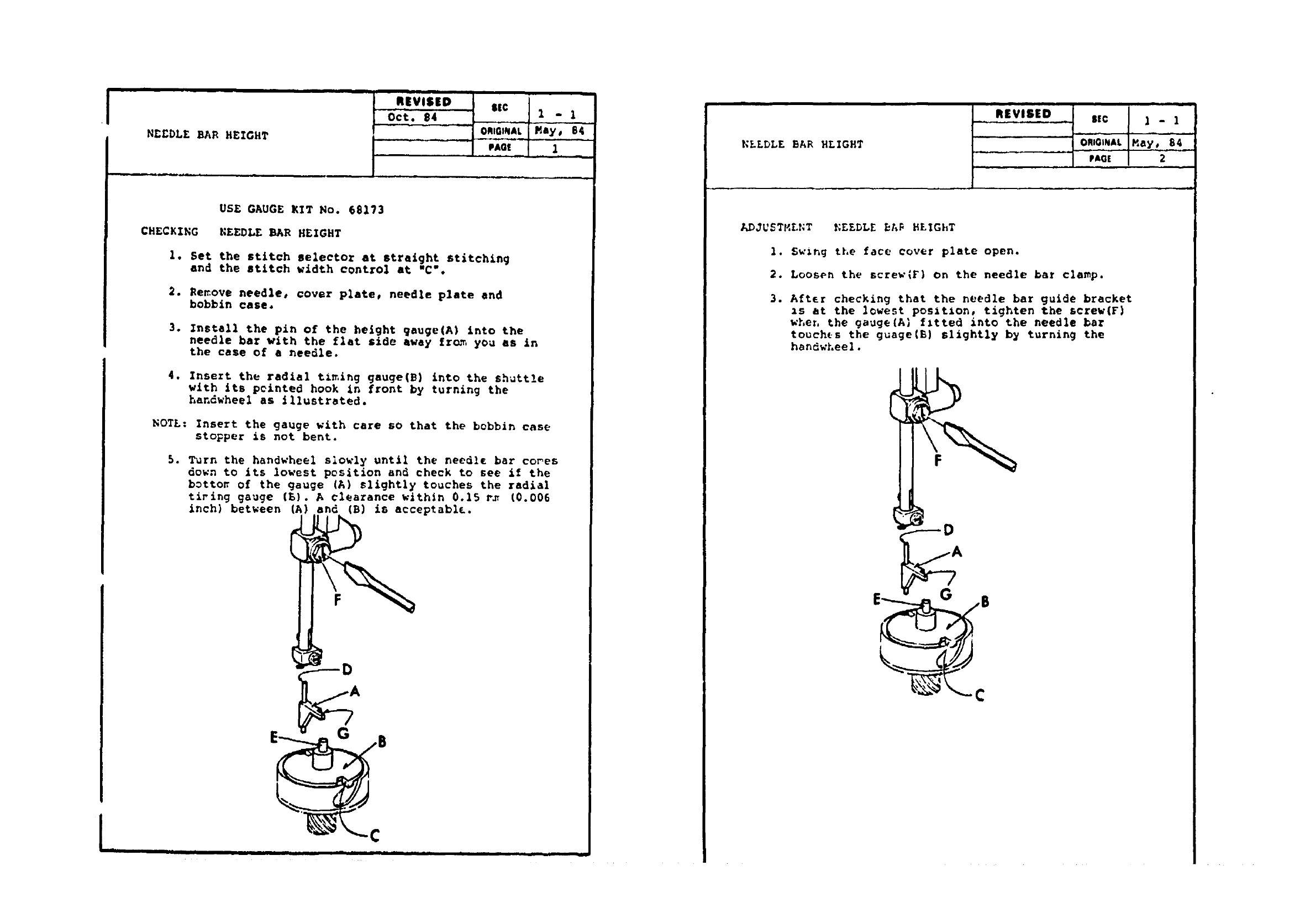
USE GAUGE KIT No. 68173
CHECKING NEEDLE BAR HEIGHT
le
2.
Set the stitch selector at straight stitching
and the stitch width control at "C'.
Re_ove needle, cover plate, needle plate end
bobbin case.
3. Install the pin of the height gauge(A) into the
needle bar with the flat side away fr_. you as in
the case of a needle.
4. Insert the radial t_ing gauge(B) into the shuttle
with its pclnted hook in front by turning the
handwheel as illustrated.
NOTE: Insert the gauge with care so that the bobbin case
stopper is not bent.
5. Turn the handwheel slowly until the needle bar co_es
down to its lowest position and check to see if the
botto_ of the gauge (A) slightly touches the radial
tiring gauge (_). A clearance within 0.15 r_ (0.006
inch) between (A) and (B) is acceptabl_.
F
G
NELDLE BAR HEIGHT
REVISED $sc 1 - 1
ORIGINAL May, S4
PAG[ 2
ADJUdTHLNT _EEDLE _A% HE%GhT
1. Swlng the face cover plate open.
2. Loosen the screw(F} on the needle bar clamp.
3. After checking that the needle bar guide bracket
_s at the lowest pos_t_on, tighten the screw(F)
whet, the gauge(A_ f;tted into the needle bar
touches the guage{E) slightly by turning the
hsndwheel.
LD
G
¢
, ,, ................ i II i iii , ,,.,.
NEEDLE TIMIt;G TO SHUTTLE
,iris=p__ 1,,: . ;-
J
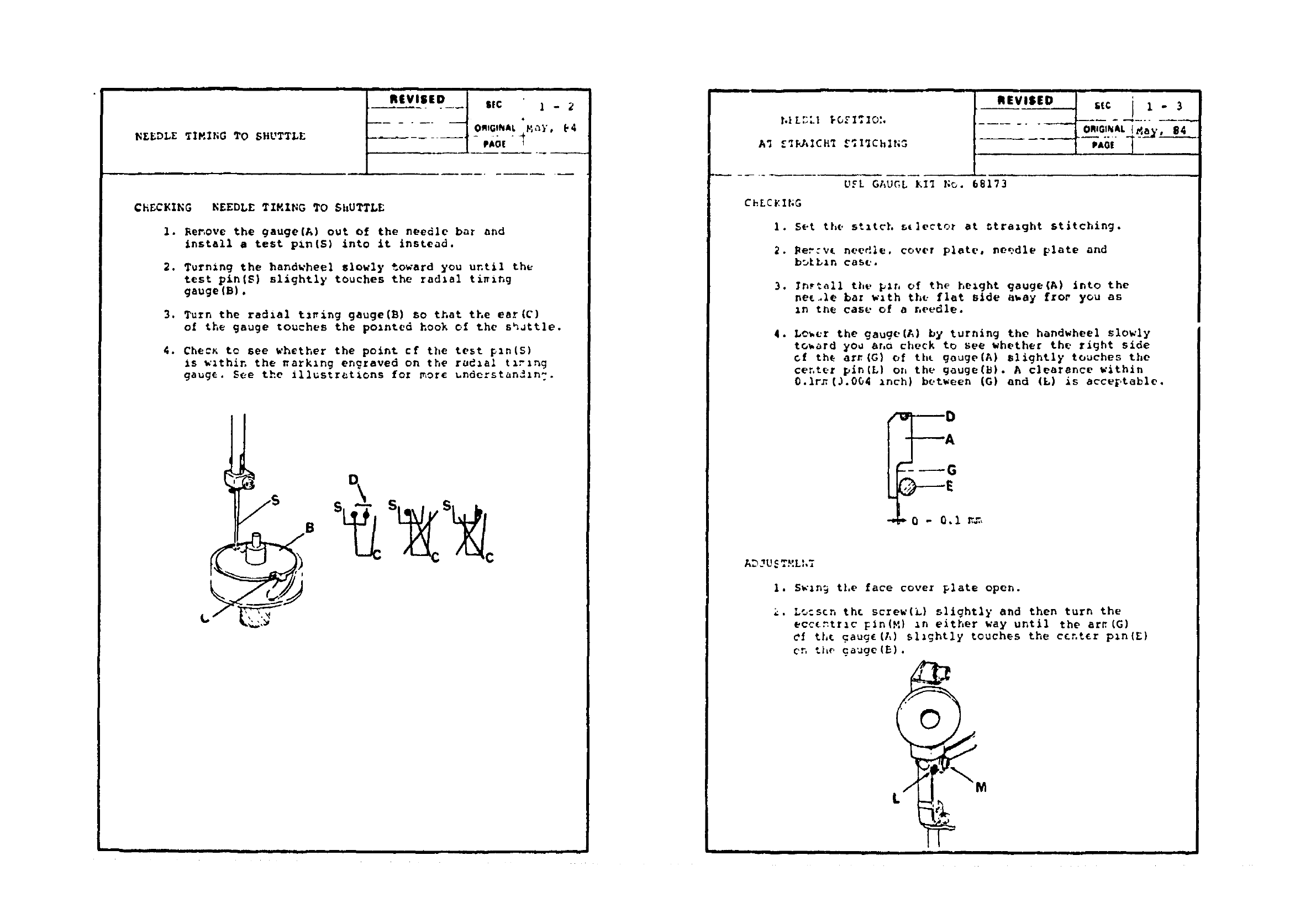
CHECKING NEEDLE TZMZNG TO $itUTTLE
1. Renove the gauge(A) out of the needle bar and
install a test pin(S) into it instead•
,
Turning the handwheel slowly toward you until th_
teat pin(S) slightly touches the radial ti_ng
gauge(B),
Turn the ra_ial t_ing gauge(B) so that the ear(C)
of the gauge touches the polnted hook of the shuttle.
4. Che:_ to see whether the point cf the test p_n(S)
Is within the narklng engraved on the radial txrlng
gauge. See the illustretions fez more understandln?.
D
[ i[
I u i
Aq .e3KAICB_ _,I_Chlt, oJ .,= j 1.3
UEL GAUGL KIT l;_. 68173
ChLC_I_;G
1. Set the stxtch 5+lector at _tralght stitching.
2. Rer:vt needle, cover plat(,, needle plate and
buLLxn cas_..
3, Inr_all the plr, of the height gauge(A) into the
me_le bar wlth the flat slde a_ay fror yOU as
In t_e case of a needl_.
•Lo_cr the gauge(A] by turning %he handwheel slowly
to_ard you ano check to see whether the right side
cf th_ am(G) of thL gouge(A) slightly touches the
center pln(L) on the gauge(B)• A clearance within
0.1rz(3.0O4 Inch} between (G) and (L) is accvF,table.
--_G
AD. U.... L,,_
1. Swln9 tl,e face cover plate open.
2. L_:stn th_ screw(L) slightly and then turn the
ecc_ntrlc Fin(M) _n either way until the ar_(G)
Cf tL_ gaug£(A) slightly touches the c£nt_r pln{£)
Cn the gauge(5).
i
DISTRIBUTION OF NLEDLE SWING
REVISED s_c II° 4
PAGE '
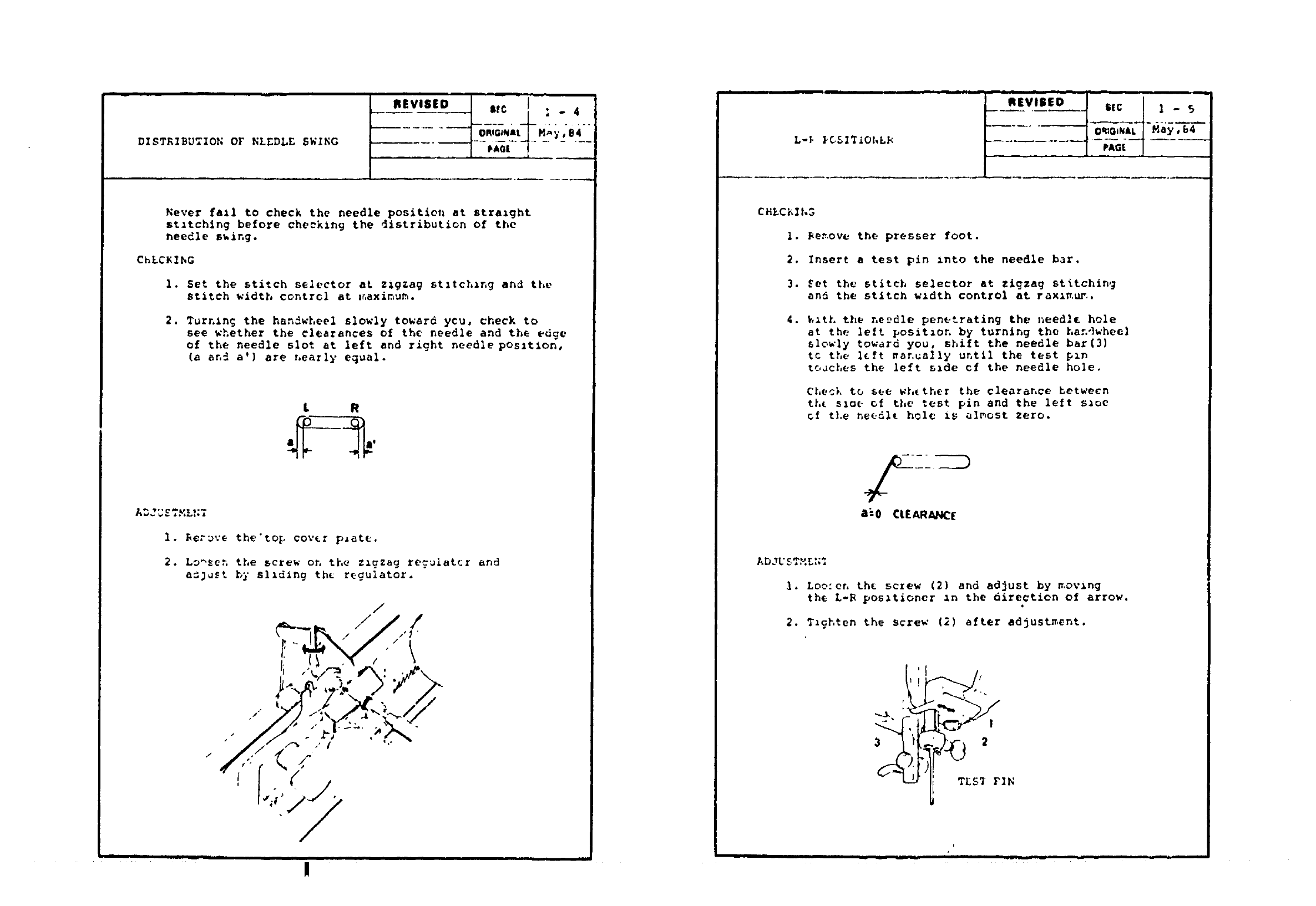
Never fail to check the needle position at straight
stitching before checking the distribution Of the
needle s_ing.
ChLCKZhG
I. Set the stitch selector at zigzag stltchlng and the
stitch width contrcl at :_,aximu_.
2. Turning the han_wheel slowly toward ycu, check to
see whether the clearances of the needle and the edge
of the needle slot at left and right needle posltion,
(a an_ a') are nearly equal.
L R
•_- Ia'
ADJUSTML_;_
I. _erDve the'top cover p_at_.
2. Lo_sen the screw on the zigzag reculatcr and
a_uSt by sliding th_ r_gulator.
/
......................... , ,=,,
I I
L-_ _CSI_LOhL_
REVISED
tSIC
ORIGINAL
PAGE
CHiCl_lh3
i. _e_ove the presser foot.
2. Insert a test pin into the needle bar.
3. Set the stitch selector at zigzag stitching
and the stitch width control at raxi_.ur..
4. _ith the needle penetrating the needle hole
at the left posit_on by turning the hanqwheel
slowly toward you, shift the needle bar(3)
tc the left _ar.ually until the test pin
%oJches the left side cf the needle hole.
Check to see wh_ther the clearance between
th_ sloe of the test pin and the left sloe
of t].e ne_dl_ hole is almost zero.
a_o CLEARANC[
ADJUSTMLN:
I. Loe:en th_ screw (2) and adjust by ,.ovlng
the L-B posztioner In the direction of arrow.
2. Tzghten the screw [2) after adjustment.
r
iJill II
i| i i i lJm
FLi_ DDG }.i]Gh=
REVISED
St€
| PAG| I
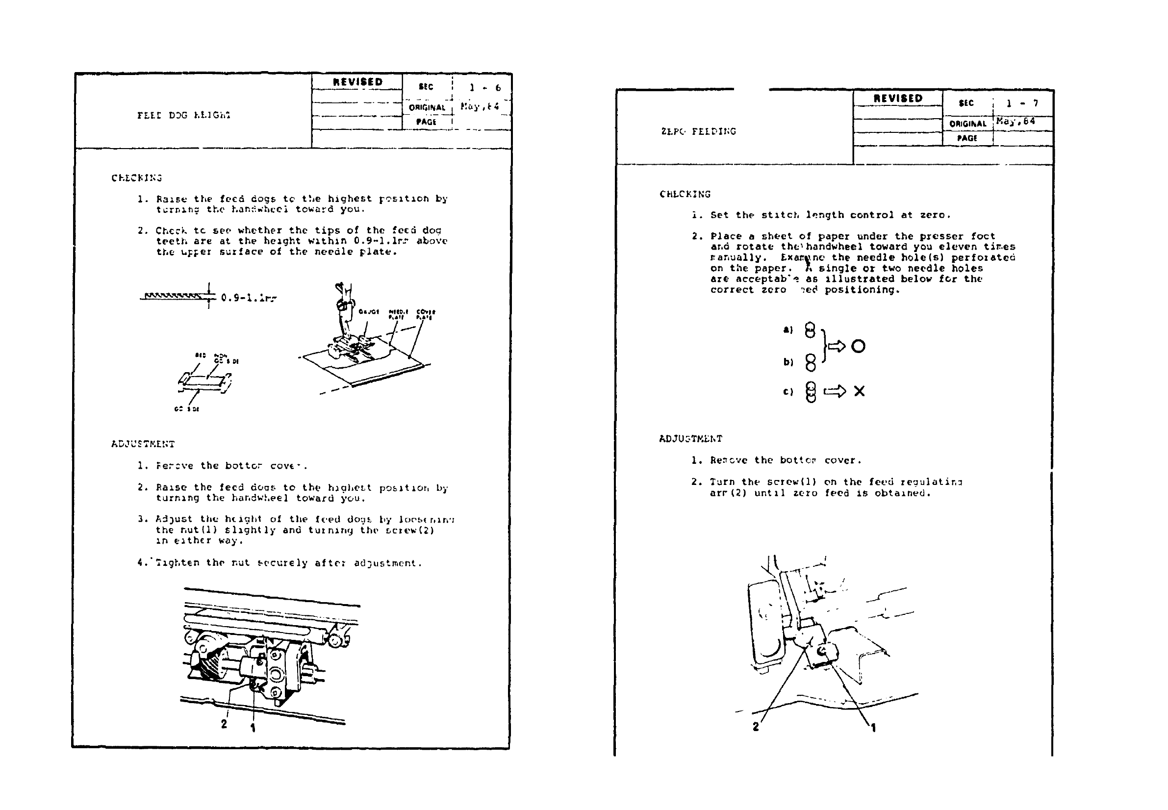
i. Ba_se the fecd dogs tc the highest Feslt_on by
t_rnln._ the han_.whcel toward you.
2. Chcck tc see whether the tips of the feed dog
teeth are at the height wlthin 0.9-1.1rr above
the u_er suzface of the needle _late.
!
,,_ _, _,
G= $:,!
G_ .,G! *,riO.! €1_,1)$
_&tLP*&t|
ADJU£TM£!_T
I. _er:ve the bettor coy{-.
2. Ealse the feed doqs to the hagheLt pos,tlor, by
turnzng the har,dwLeel toward you.
3. AJ)ust th_ h[i_ht of the f_'ed dou_ by loes{r, ln';
the nut(1) sllghtly and tuzn_ng the screw(2)
In e_th_r way.
4.':_ghten the nut _ecurely afte_ ad]ustment.
2I
i I
ZEPO £EIDIr:G
., ....
REVIS[D
ml Ill
s_c ; 1 - ?
I
tOm6,_,AL Ma_',E4
CNLCK]NG
i. Set the stitch length control at zero.
2. Place a sheet of paper under the presser foot
ar,d rotate the_handwheel toward you eleven tir.es
_anuall¥. Exan._ne the needle h01e(s) perfozated
on the paper. A single Or two needle holes
are acceptab*e as Illustrated below _or the
correct zero _e_ positioning.
ADJU_TMEhT
i. Be_ve the botto_ cover.
2. Turn the screw(1) on the feud regulatin_
arF(2) untll zero feed is obtained.
I-
• _ i i , ,m, iii
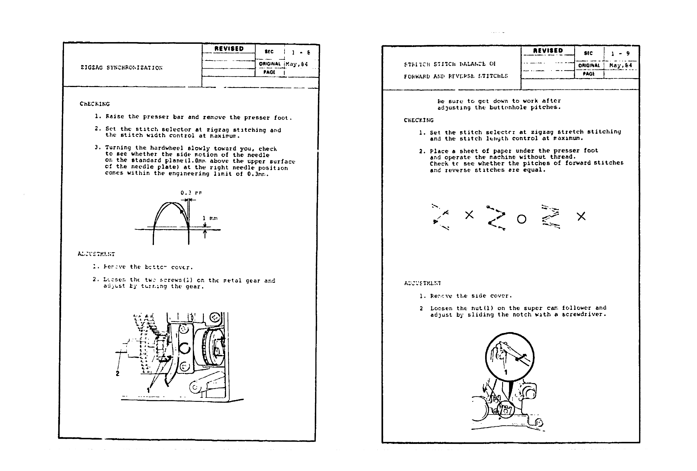
CHECKING
I. Raise the presser bar and remove the presser foot.
2. Set the stitch selector st zigzag stitching and
the stitch width control at maximum.
3. Turning the hardwheel slowly toward you, check
to see whether the side motion of the needle
on the standard plane(l.Om,, above the upper surface
of the needle plate) at the rlght needle poslt*on
co_es within the englneerlng l,mit of 0.3mn..
0.3 _"
ALJL'ETy.L!;T
"_er=ve the b=ttc- cov_r.
2. Ltcsen th_ tw_ screws(1) on the _etal gear and
adjust _' turning the gear.
'1..I
i
STBIIC}| S_I_CII I_ALAt,=_- Ol
FO_WABD At;D PFVL_SE f,_ITChLS
.......... __o;,O,_,,a_';_-'--
-...... i-;_,--V ......
Be sure to get down to work after
adjusting the buttonhole pitches.
C_S¢ZlNG
i. Set the stitch selectee at zigzag stretch stitching
and the stitch length control at .aximum.
.Place asheet o£ paper under the presser foot
an_ operate the n,achine without thread.
Check to see whether the pitches of forward stitches
and reverse stitches ere equal.
_ X 0 Y"
i. Re_cve the side cov_r.
2Loosen the nut(1) on the super can,,follower and
adjust b_' sliding the notch wzth a screwdriver.
I
m L I
BU_[LT..It; BUTTONIIOLL COt;'I_OL
..... t, j
REVISED Sic i1 1('
......... ,,Q, /_. _l__
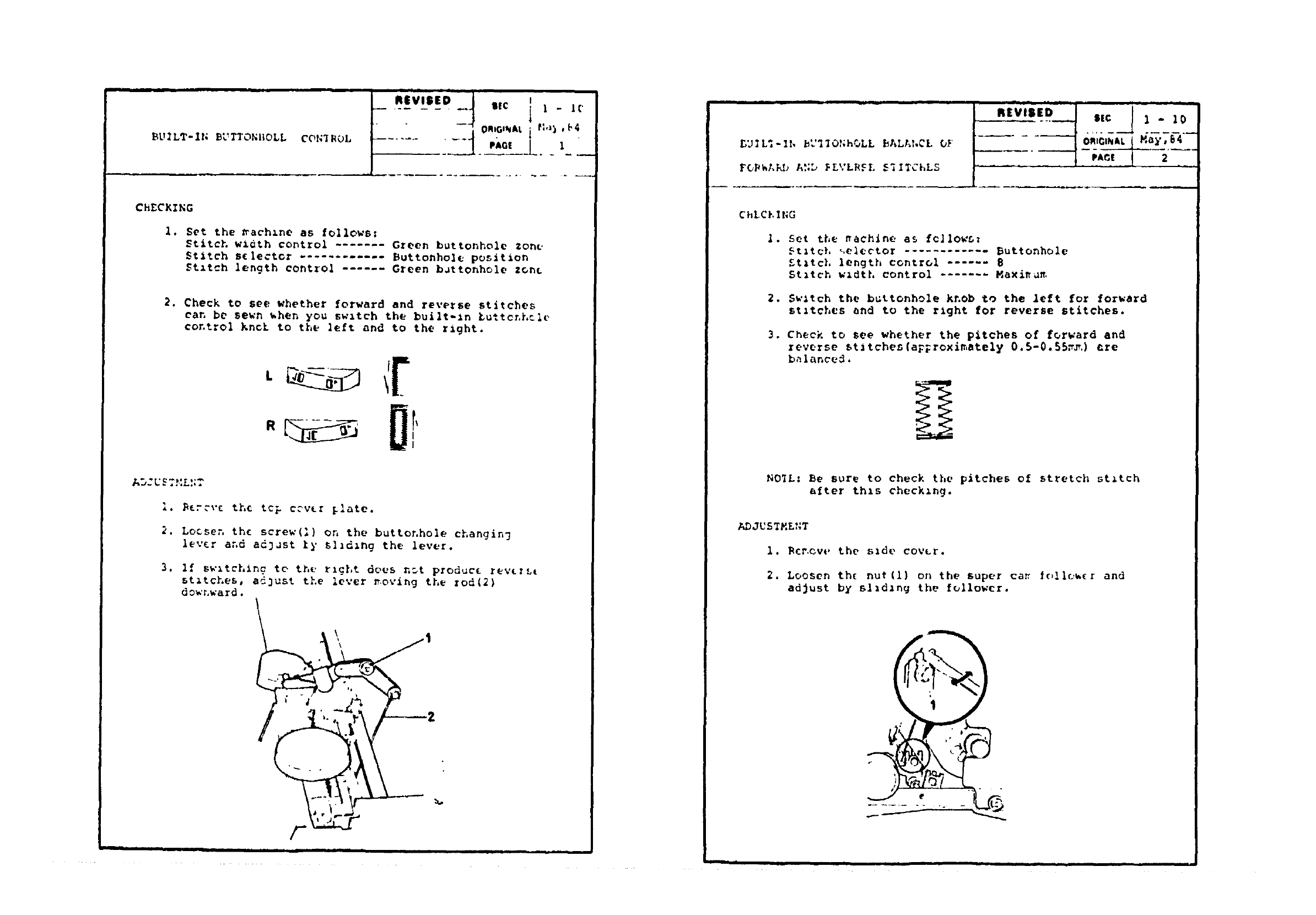
ChECK2NG
1. Set the _ach_ne as follows:
Stitch wzdth control ....... Green buttonhole zone
Stitch selector ............ Buttonhole position
$tztch length control ...... Green b_ttonhole zonL
2. Check to see whether forward and reverse stitches
can be sewn _hen you swltch the built-ln _u%tor.L%le
control knch to the left and to the right.
Aw, U_ ,. _.,,
I. _zc_'c the top c?vLr _late.
2. Lo&ser, the screw(1) on the buttonhole changing
lever and adD_st _y s1_d_ng the lever.
3. If sw_tchlng te th_ rlgLt does nDt produc_ revtrLt
stitches, adjust the lever _oving the god{2)
downward.
2
%.
I I I i I
F
II | Im
BUIL:-II, b_'I;O,.h.,LL bALA_,Ci OF
FGPhAKD A.._, _LVL;LCL S'_ITChLS |PA(_! 2 ..
ChLCt, ING
3.
Set the nachlne as fellows:
St;teL ,.elector ............ Buttonhole
£tltch length control ...... 8
Stitch w_dth control ....... Maxi_
Sw;tch the buttonhole knob go the left for forward
st;tches and to the tight for reverse stitches•
Check to See whether the pitches of forward and
reverse st_tches(a_;roxlmste_¥ 0.5-0.55r_.) are
balance_.
NO_L: Be sure to check the pitches of stretch stitch
after thls checking.
ADJUSTMENT
i. Rot.cut, the slde covtr.
2. Loosen th( nut{l) on the super ca_ follo_(r and
adjust by sliding the follower.
II ii i i i iml ii
$TA._'DAIIP FI_FD 1_I=C_ (F PAT1F_;F ----[ ;i.i 7 " ---
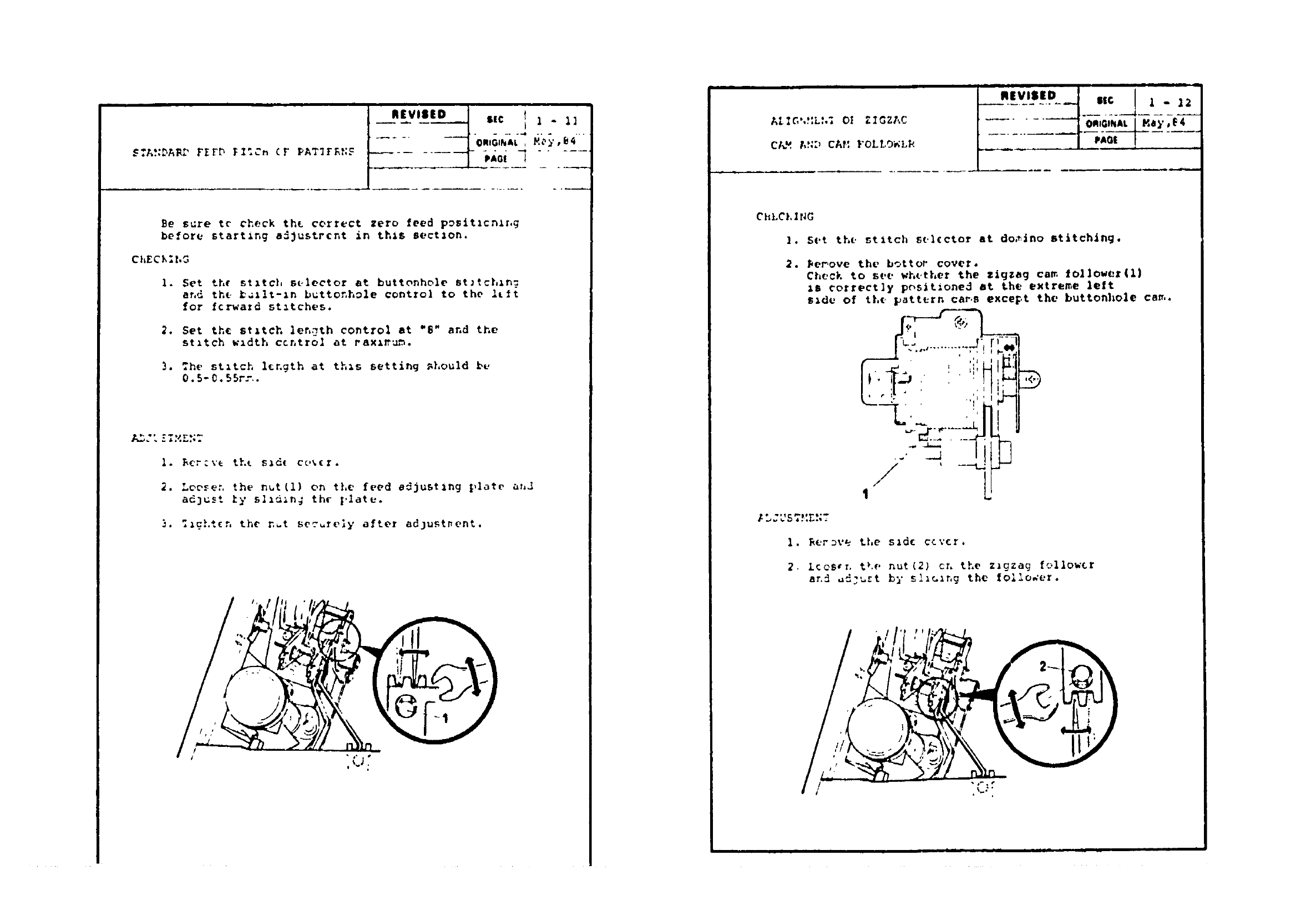
Be s_re tc check th_ cerrect zero feed pDsitlc_lr, G
before starting a_ustrcnt in this sect/on.
ChECL;t,G
1. Set the stitch selector at buttonhole St_tchzn_
and the ballt-ln buttonh_le control to the Itlt
for fcrwazd starches.
2. Set th_ stztch length control at "$" and the
stitch w_dth central at raxz_u_.
3. =he stitch l{ngth at th_s setting _hould be
0.5-0.55r:..
1. _¢r:ve tht s_d{ co%{r.
2. Looser. the nut(1) on tLe feed adjusting [,late ahJ
adjust fy sI_d_n; th¢ I,latu.
3. :igLt(n the n.t securely after adlustpent.
I
ALIG',HL',; Ol Z(GZAC
Ct_" AF:_ CAt: FOLt, O_Lk
'"n(vis(o ,,c " .
l ?i_i
ChLCklNG
1. Set the stitch st.l(ctor at domino stitching.
2. _er,ove the b¢ttor cover.
Check to see whether the zigzag ca_, followez(1)
_$ correctly p_slt_oned at the extreme left
s_dt, of th¢. pattern car, sexce_,t the buttonhole cam.
•., .......... _'! r el
1. RerD%'e the sld_ ccv{r.
2Looser. the nut(2} or. the z_gzaq follow{r
_._.t by sl_G_r,g the follower
I I • I III
.to ii- 13
...... I ORta,_,AL"'
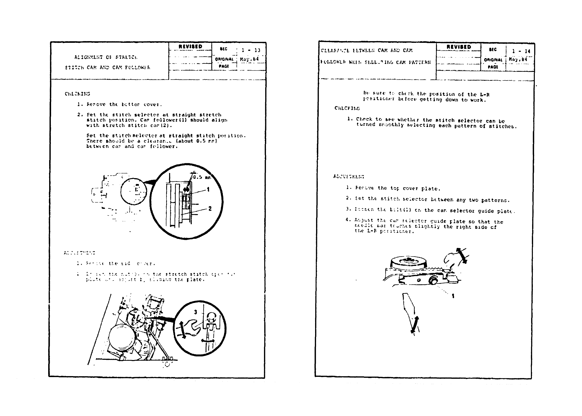
ChL_KIN3
2.
Rerove th( batter covet.
Set %hi stitch teloetor at straight stretch
stitch l,o_tion. Cap follower(l} should aligr,
watt, stretch stitch coe|2}.
Set the st_tchsel('ctor at straight statch pt.tition.
:nora shooid be a cltora_.L [about 0.5 r,_)
bttwtcn ca) and c_e f(_llower.
Al .-.__.,_.-.,_
l. _-,- :.._ the t._d c" ,'_r.
}'-_:< ,-'- _-;i-:'- ._. :_.xx:,: t:.t |late.
$
CLLA_J',._L ILTWLLH C_ AN-'_ CI_
£,LLOWLk Wt;t b SLLL." lhG CI_, ],AT',q:kN
I II i |
bt. _ute t:. e|,_."k the position of the L-_
|,._._%zOnt': btlore _ettin_ down to work•
ChLCY _hG
I. Check 1o _ee %'het],tr the stitch selector can be
turned st. ooLhly st,leetlng each pattern of t_tttche_,.
Aw. L. •_.L..,
I. Feruve the to_ cover plate.
2. £et the stitcL selector L_tueen any two patterns.
3. l::_n tI.t t:lt(1) or, the can $electo: guide platt.
4. g_3_t th_ c_ _t;ecttr guide _late so that the
r,te21{ _az tc_c).ts _Iz_),tl)' the raght s,de cf
tr,e L-B p:_zt_cr.e_.
1
..... iii , ,m, |m I I i i i Jii i • J .
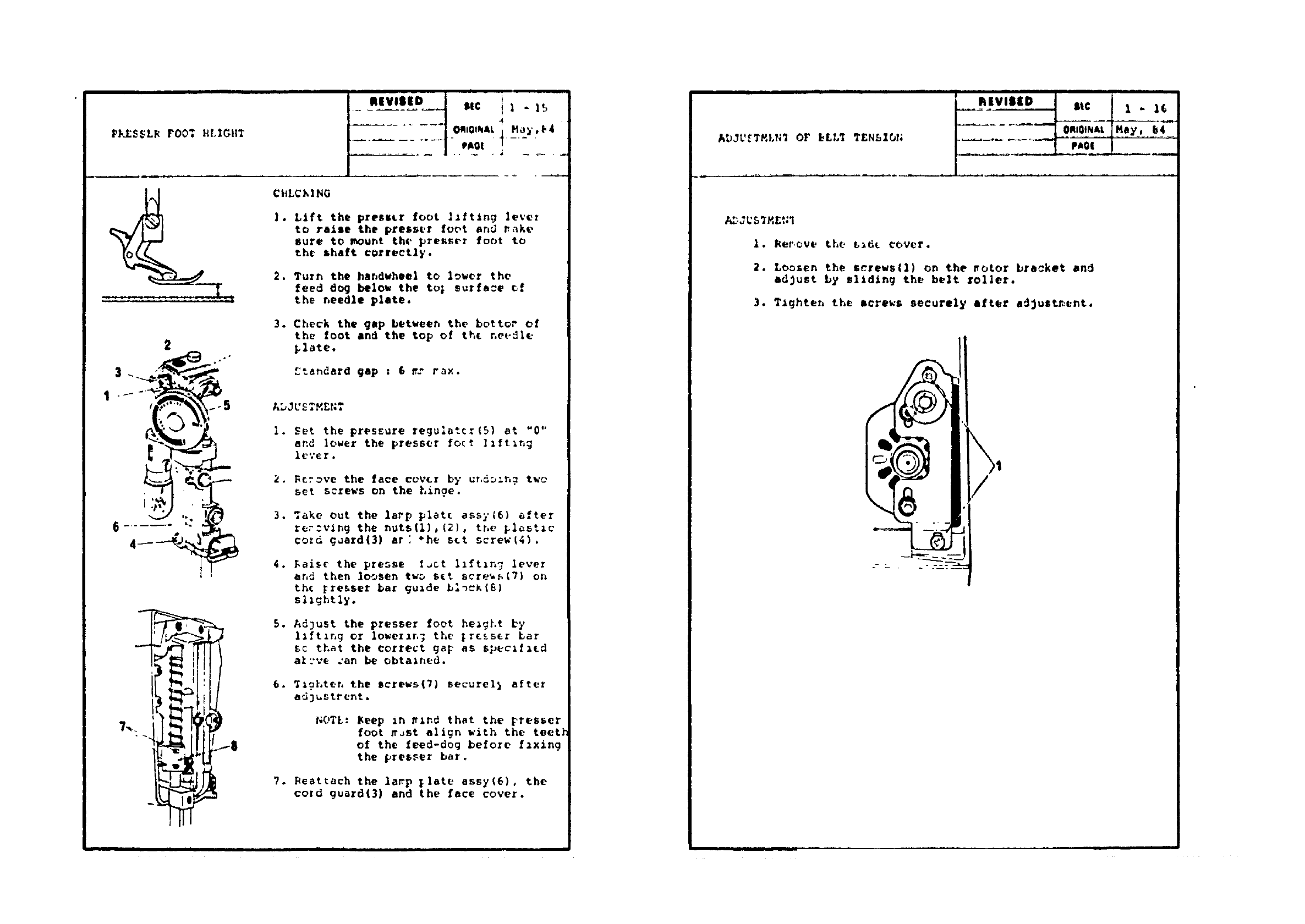
I_KES_LR FO0_ HLIGIIT
Zq :Z Z: Z:q :: _C : L C C_
8
•mEvlm DI!
........ $1C 1"15
..... -10mmOl_&t M_,y,F4
CHLChINO
]. Ltft the presser foot lifting lever
to raise the presser font and rake
sure to _ount the presser foot to
the _haft correctly.
2. Turn the ba_dwheeI to lower the
feed d_ below the to; sutfa:e cf
the needle plate.
3. Check the Osp between the bottv_ of
the foot and the top of the needle
_late.
£tandard gap : & v.y r,_x.
AL,Jt.'E T,v,ENT
I. Set the pressure regulator(5) at "0"
and lower the presser foot ]Ift_ng
l_vEr.
2. Fcr_ve the face cvvLr by ur,d_n_ two
set screws on the hinge.
3. Take out the lapp plate assy(6) after
ler:ving the nuts(1),{2), tr,e _lastzc
cozd gaard(3) at: *he set screw{4).
4. Daisr the presse f_ct hftzn 7lever
end then loosen two s_t scre_s_7) on
th_ _resser bar guide b;_=K(G)
sl_ghtIy.
5. Ad)ust the presser foot height by
llft_ng or lower_r,7 the |r{ss_r Bar
_¢ that the correct gap as spec1(;ed
alzve can be obta*ned,
6, _gLt_r, the screws{7) securel} after
ad_ustrent.
NOTL: Keep _n ._nd that the presser
foot _.st align with the teet]
of the feed-dog before fzxing
the _res_er bar.
7. Beattach the la_p _late assy(6) 0 the
cozd guard(3} and the face cover.
|I
ADJU_TMLN_ OF I_LL_ T£N&IO_;
I. _erove the b_dt cover.
2. Loosen the screws{l) on the _otor bracket and
adjust by sl_dlng the belt roller.
3. Tighten the screws securely after adjusted:ant,

THIS PAGE
INTENTIONALLY LEFT
BLANK
THIS PAGE
INTENTIONALLY LEFT
BLANK
