Kenmore 15819460 User Manual SEWING MACHINE HEAD Manuals And Guides L9090162
KENMORE Mechanical Sewing Manual L9090162 KENMORE Mechanical Sewing Owner's Manual, KENMORE Mechanical Sewing installation guides
User Manual: Kenmore 15819460 15819460 KENMORE KENMORE SEWING MACHINE HEAD - Manuals and Guides View the owners manual for your KENMORE KENMORE SEWING MACHINE HEAD #15819460. Home:Laundry & Garment Care Parts:Kenmore Parts:Kenmore KENMORE SEWING MACHINE HEAD Manual
Open the PDF directly: View PDF ![]() .
.
Page Count: 6
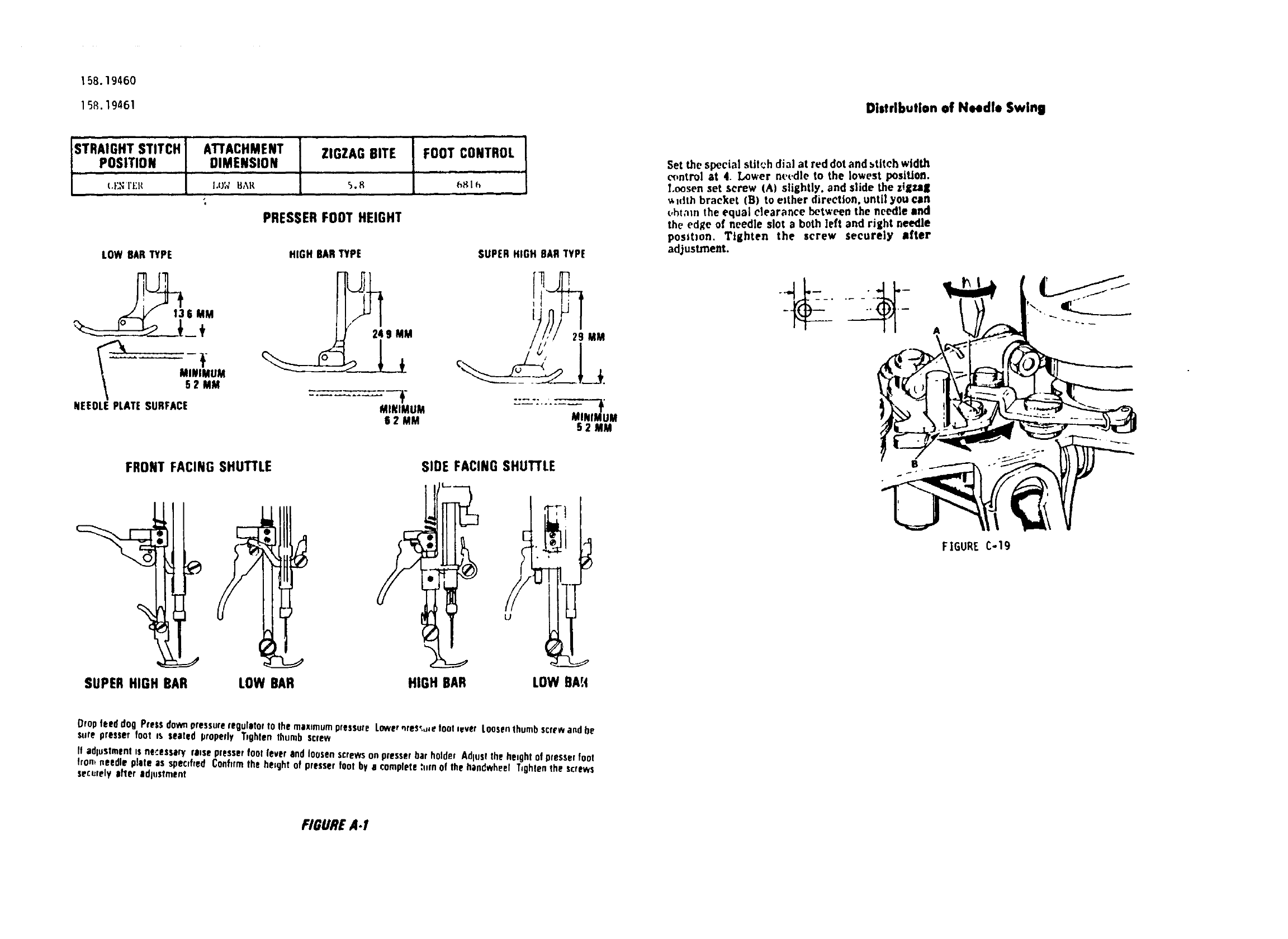
158.19460
158.19461 Distribution of NHdlo Swing
STRAIGHT STITCH ATTACHMENT ZIGZAG BITE FOOT CONTROL
POSITION DIMENSION
(.I':NI't:g 1.t£¢ BAR 5.8 _ I h
PRESSERFOOTHEIGHT
LOW BAR TYPE
6 MM
_÷
52 MM
NEEDLE PLATE SURFACE
HIGH BARTYPE
MINIMUM
62 MM
SUPERHIGH BARTYPE
29 MM
52 MM
Set the special stlt'_h dial at red dot and stitch width
('_ntrol at 4. Tower needle to the lowest posiUon,
Loosen set screw (A) slightly, and slide the ztgXal
v,lrtth bracket (B) to either direction, until you can
(,htam the equal clearance between the needle and
the edge of needle slot a both left and right needle
positron. Tighten the screw securely after
adjustment.
A
FRONT FACING SHUTTLE SIDE FACINGSHUTTLE
SUPER HIGH BAR LOW BAR
U
HIGH BAR LOW BAt4
FIGURE C-19
Drop feed dog Pressdown pressureregulatorto fhe maximumpressure Lower,_res';,J,etootlever Loosenthumbscrew andbe
sure presser foot is seated properly T,ghten thumb screw
ff adlustmentis ne_.essan/raise presserfoot lever and loosenscrewson presserbar holder Adlustthe he,ght of presserfoot
fromneedle plate as speclfrerJConfirmthe herght of presser foot by e complete,*urnof the handwheel Tighten the screws
secerely tiler adlostment
FIGUREA.I
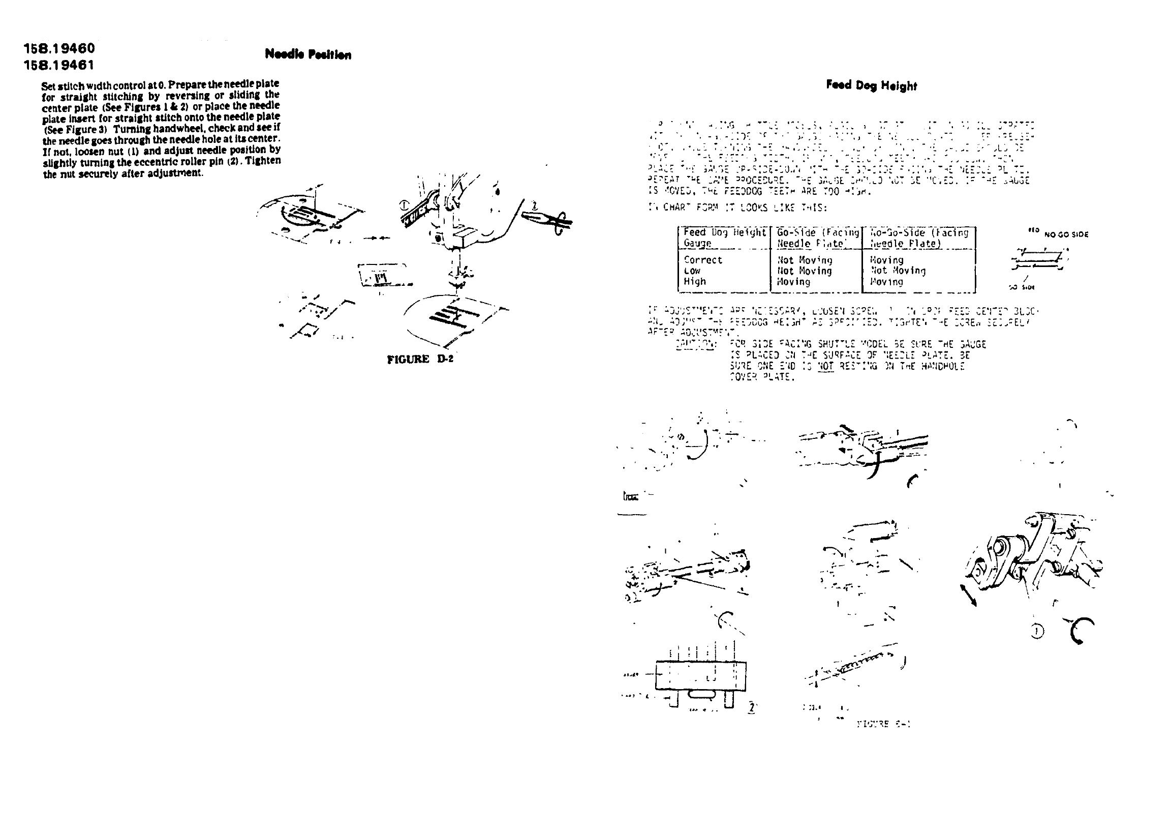
158.19460
158.19461 Needle Peelfle.
Set sUteh width control at 0. Prepare the needle plate
for straillht stitchinll by reversing or sliding the
center plate (See Fillure$ I & 2) or place the needle
plate insert for straJllht stitch onto the needle plate
(See Fl&,ure 3) Turnlnll handwheet, cheek and see if
the needle goes through the needle hole at its center.
If not, loosen nut (t) and adjust needle position by
slightly turninl the eeeentrle roller pin (2}. Tillhten
the nut securely after adjustment.
FIGURE D-Z
Feed Dog Height
:} " ' ........,_.. ,G _"4.: _'..:_,..'.','.. _ "',, :........ ,., ._. _'_:':'. .
-_[.'[,_T "="E "'' .............
'" . _OKS '' :• , CHAR" _3P_"_'T '^ .,K_ ,,,I.:
F--_ Dog i,eight [-G-o--Si-de-!Facing[ i,o-3o-Side (Facing I .o NOOOS,D{
.Go--_L...... l-_L_t _,,,t__--__,_,__-____rJ.____..... I "I '"
Correct I :lot14ovlng I Hoving I --_ '
LOW |!lotMoving _ ;lot"4ovlng -_ /
lHigh I'I°ving V'°v Ing J _ ,,o_
_h. _,3;''_""-._:._Z_,OC3_E:;_" ,:_3PC_:''F.]._'3eTZ',"_E ZCRE,-,IZ].:EL_
_F-[_ =,O.'UST'._F',".
-_'":q',: 'Cq 3_3E "AC;';GSHUT'LZ "CDEL 5E ._URE-HE 3AUGE
:_ _LZCZD C'IT_E SURFZCE OF ':E;_._LZaL,_TE.5E
SURE O;;E-"ID:S ';OTRE'.":'iG)N T_E HA:IDHO!-"
COVE_,PLATE.
",..:' _]
(, I
• ,. :.-_,,-_
._ ,_.4:.._---.._._._,'_!
_'"_" I ""
=.,
!
-L
/

1 58.19460
158.19461 Zero-F_ding
Set stitch length control at "0". Turning handwheel,
cheek and see zfthe feed dog moves horizontally. At
"0" position the feed dog should not move. It _tdoes,
loosen screw (A_ and lneert the eeeent_, tool (B_
into the hole (C). Turn the eccentric tool e|'.her way
to elinlinate movement of the feed dog. Tighten the
screw (@,_aftPr "_dJu_tment.
FIGI.'RE F-I_
NEEDLE TIMING TO SHUTTLE
NEEDLE BAR HEIGHT
THE RADIAL TIMING GAUGES AND TEST PINS, AS
ILLUSTRATED BELOW, ARE AVAILABLE FROM DIVISION
92, SOURCE 192. THE KIT IS IDENTIFIED AS
#69659. EACH GAUGE AND TEST PIN CAN ALSO BE
ORDERED INDIVIDUALLY.
THIS KIT IS USED FOR SOURCE 148 AND 158
VERTICAL BOBBIN S_ING MACHINES.
RAD'IAL _ i T
IIf.lINGGAUGE _-".,.
_69894 . '- TEST PIr_
_'_ #b9_73
I
j
RADIAL _"
TIMING GAUGE
%9892 ',
RADIAL
TIMING GAUGE
#69B93
RADIAL
TIMING GAUGE
FIGURE G-I e69895
NEEDLETIMINGTOSHUTTLE
On not attempt adJuStmentsother than those spocd,ed m
tills manual Jl. by follpw,ng the prescribedprocedures,d is
determinedthat a mach.nPis out of radial trine, handle per
Bulletin $.820
Radial Timing Gauge
Instructions
IRemoveneedle and replaced with test pmwh,ch has e
blunt lip
2 Remove bobbin case and shuttle hook Insert correct \
tad,el timing gauge into shuttle driver
For th,s ntodel(sl use gauge marked
$n _rcJ 158 FROPdT5 8 FRONT 4 0
Use FRO?_r58 mathng
3 Set stitch control at "0""or '5" tdependmg on model
involved)
4 Set needle posJhon controlat center tot n,odelswhich
have Ibis _ootrol
5 Rol,,te handwheelslo_'dybyhand /See Figure G.3a t The
test pm should come between the correct|wo v_r_ical
hoes at the end of the counterclockwiserotation of the
gauge Forthis modells) useverticallinesidentifiedcnth
one dot DIM[ NSION A
6 Tocheckneedlebarhe_ght. contmuetorotatehsndwheel
slowly byhand /See FigureG 3b JAt the Iowes; positron
ot the needle bar, the end of the test pin shouldcome
between t_o hoftcontal hnes on the gau,_e
if necessary, adlust needle,bar hllght Loosenscrew on
needle bar holder pod adlusl he,ght on the test pm
Zig_:ql Synchronization
Set stjiteh width COntrol at maximum. Turning ,,he
handwheeI, check and see if the needle side .-::.orlon
on the standard piano _0o394 :nch above the uplP._r
surface ol the needle plate, at both needle p_slt_uPs
come wtthin the engineering ]lmR of 0.0138 inch. £f
nL," _ooset, set screw s2_ on the wor/n gear eztl_er
direc,;_n. Tighten the screw ,2) securely j,qer
adjustment.
.... ., L..-" \\
DIMENSIONB
FIGUREG-3
F,gure G.3 gives a general idea of tho use of the radrul
hmmg gauge Follow the snstructronSat the loft wh_h
pinata to th_s modells_
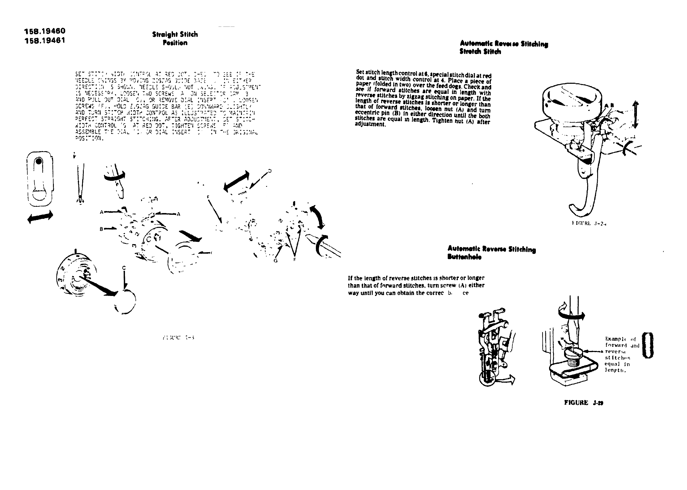
158.1 g460 Straight Stitch
158.19461 Puitlon Autematic leve, te Stitching
Stmch Stitch
)_. b ', ; ... ," s[ ^'; "_ "'" °"
,.E..L_.*,,,_S TM "_; :_;G"'_''3_ ....
j,R..... _ S _0.,.,. IE:_L_.S_ubL., ';OT ..,.,._.
;S 'IECES_'P'. LOOSe',T..,OSCrEwS _ ,_,1"SE.ET':_ ""_._3
_JlO _'' _ ' '"'' ''_ne''3,_L OR, ;,EMo'/r ;'IST_" "'.L, 3UT '.j,
3CRE'4_.._F,, "OL_ Z.G::,GGUI3E BAR '.E_........,u.,,,,_P._...... _,",,_'
A_ID"* '
,..R.I3TI'CH .'I.3T#'_.ON"POLA: .......;'" .... 'IA,......I.-.l
..... _ ,_-_,,IG.;,F'zR AD_,U...._.,., ._E" S":T_,-
, ÷ .... ..,- ._,. _;l{_.4,D,,_ ,..O,hROL 'G _T RE3 30T, TIGHTE'I _"?c ,r .-'
tSS_4BLE ' r"?' ;A _ ';r LJ O . O : _L .......' ;S_"m ' : tI " '' _. J_', _,._.......
OS..O,i.
,_t sdteh len_h control at &"lw'clal stJtehdlal at red
:l:o,¢oro ,. ,1.,o
. , _over me feed dolls. Cheek and
see if Iorwam lt/tehes are equal In lenlth wi_
r_verme stitches by _lzag stitching on IxlPer. If the
length of reverse ltltehel is Ihorter or longer than
that ot forward _tches ' loosen nut (A) and turn
.equal mlength. Tighten aut (A) after
adJu_unent.
". -_.- A,; . "/_, @ ".: _-
' "'.'" 1"V _._-'_ iutematic ltW_ Stitching
If the len_h of reverse sUtehes is shorter or longer
than that of f,_rward stltehes, turn screw IA) either
way until you can obtain the corree b. ce
FI ;I.'R:Ti-_,
'I
_I_'RL J'2_
Ex_plc ,,f 0
fnrwa rd and
Yever _
stitch._
equal in
length.
FIGURE J.l_
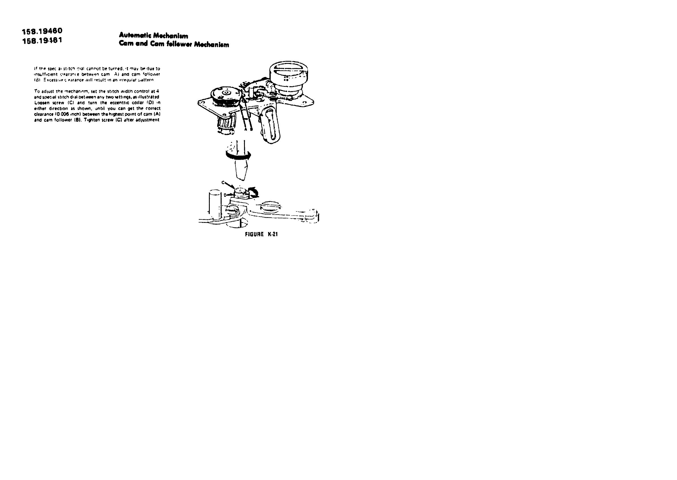
159.19460 Avtemotic Mechonism
158.19561 Cam and Cam fellewor Medlonkm
TO tdlust _hl ._eche_._rn, slit the stl_cil _,dttl control it 4
ilnd special _tltch d,al _lt w_n any two _lttln_e. _ _llut'.ret/d
I.o<Hi4n screw (C) e_d _urn trail e¢cent;'_¢ coillr fO) ,n
_lthilf direction a_ _.hown. _ntll you ¢_ln gqt th_P_orrilct
clearance {0 00_ ,nc_) between thil h,gmrst point of c,lm |A)
end cam follower (IlL T,gntiln screw (C| att_t _dlustment
FIGURE K,21
