Kenmore 229960230 User Manual GAS FIRED BOILER Manuals And Guides L0511245
KENMORE Boiler Manual L0511245 KENMORE Boiler Owner's Manual, KENMORE Boiler installation guides
User Manual: Kenmore 229960230 229960230 KENMORE GAS-FIRED BOILER - Manuals and Guides View the owners manual for your KENMORE GAS-FIRED BOILER #229960230. Home:Heating & Cooling Parts:Kenmore Parts:Kenmore GAS-FIRED BOILER Manual
Open the PDF directly: View PDF ![]() .
.
Page Count: 30
Owner'sManual
CONTINUOUSPILOT
MODELNO.
229.960330
229.960340
229.960360
229.960360
229.960370
229.960380
229.960390
ELECTRONIC
INTERMITTENTIGNITION
MODELNO.
220.960230
229.960240
229.960260
229.960260
229.960270
229.960280
229.960290
Theseinstructionsmustbeaffixed
onor adjacenttotheboiler.
CAUTION
Readall instructionscarefully
beforestartingtheinstallation.
Save this manual
for future reference.
®
Gas-Fired
Cast Iron
STEAM
BOILER
• Installation
• Operation
•RepairParts
WARNING: Improper installation, adjustment, alteration, service or
maintenance can cause injury or property damage. Refer to this manual.
For assistance or additional information consult a qualified installer,
service agency or the gas supplier. Natural gas boilers are not to be
converted to Propane gas.
PRINTED IN U.S.A. FOAM e37-_00-02_02-6"7949
Warranty .................................................... 2
Rules for Safe Installation and Operation .................. 3
Boiler Ratings and Capacities ............................. 4
Before You Start ............................................ 5
Locating the Boiler ......................................... 5
Fresh Air for Combustion .................................. 6
Installation - System Piping ............ : ................... 7
Chimney and Vent Pipe Connection ....................... 10
Vent Damper Operation .................................... ! 1
Gas Supply Piping ......................................... 12
Electrical Wiring ............................................ !3
Controls and Accessories - What They Do ............... 19
For Your Safety - Read Before Operating ................. 20
Operating Your Boiler ...................................... 22
Checking and Adjusting ................................... 23
Cleaning Your Boiler ....................................... 24
Maintaining Your Boiler ...................................... 25
Service Hints ............................................... 26
Repair Parts ................................................ 27
E_ AIRS
KENNMORE CAST IRON BOILERS
FULLONE YEARWARRANTYON HOTWATERAND GAS STEAMCASTIRONBOILERS
For one {1) year from the date of installation, when this boiler is installed and maintained in accordance
with our instructions. Sears will repair defects in material or workmanship in the boiler, free of charge.
LIMITED 12 YEAR WARRANTY ON STEAM CAST IRON BOILERS
After one {1)year and through twelve (12} yearsfrom the date of installation,Sears willfurnish a replacement
heat exchanger, if the heat exchanger in the boiler is defective. YOU PAY FOR LABOR.
LIMITED 20 YEAR WARRANTY ON HOT WATER CAST IRON BOILERS
After one (1)year and through twenty (20) years from the date of installation,Sears will furnish a replacement
heat exchanger if the heat exchanger in the boiler is defective. YOU PAY FOR LABOR.
SEARS INSTALLATION WARRANTY
In addition to any warranty extended to you on the Sears merchandise involved,which warranty becomes
effective the date the merchandise is installed, should the workmanship of any Sears arranged installation
prove faulty within one year, Sears will, upon notice from you, cause such faults to be corrected at
no additional cost to you.
FOR WARRANTY SERVICE, SIMPLY CONTACT THE NEAREST SEARS STORE OR SERVICE
CENTER THROUGHOUT THE UNITED STATES. This warranty gives you specific legal rights, and
you may also have other rights which vary from state to state.
IMPORTANT
The following are the responsibilities of the user and are
not covered by the Warranty
1. Filter cleaning or replacement.
2. Damage to unit or unsatisfactory operation due to improper
cleaning or use of unit in corrosive atmosphere.
3. Damage to unit or unsatisfactory operation due to blown
fuses or inadequate or interrupted electricaI protective
devices.
4. Damage to unit caused by the use of components or other
accessories not compatible with the unit.
5. If the unit is removed from the place it was originally
installed, this Warranty becomes void.
6. Damage to the unit caused by accident, abuse, negligence,
misuse, riot, fire, flood, or acts of God.
SEARS ROEBUCK AND COMPANY
D/817WA
Hoffman Estates, IL 60179
®,_E 2
1. Read the Owner's Manual carefully Failure to fallow the
rules for safe operation and the instructions can cause
a malfunction of the boiler and result in death, serious
bodily injury, and/or property damage.
2. Check your local codes and utility requirements before
installation, The installation must be in accordance with
their directives,
3. Before servicing, allow boiler to cool. Always shut off any
electricity and gas to boiler when working on it. This will
prevent any electrical shocks or burns.
4. Never test for gas leaks with an open flame. Use soap
and check all connections. This will avoid any possibility
of fire or explosion.
5. Be certain your new boiler will be using the correct gas.
Overfiring will result in premature failure of the boiler
sections and cause dangerous operation.
6. Never vent this boiler into an enclosed space. Always vent
to the outside. Never vent to another room or inside a
building.
7. Be sure there is adequate air supply for complete
combustion.
8. Follow a regular service and maintenance schedule for
efficient and safe operation.
TOOLS
Pipe Wrench
Screwdrivers
Tin Snips
6 foot tape or folding rule
Hack Saw
LP Torch, if you have copper piping
Pipe cutter and threading tools
(for iron pipe systems)
MATERIALS
Pipe joint compound suitable for natural and propane gas.
Iron or copper pipe for the water lines,
Black pipe for the gas lines.
Miscellaneous fittings.
Solder and flux if you have copper piping.
The following booklets will help you in making the installation:
Electrical Wiring - Available at Sears from the Plumbing, Heating or Electrical Departments at nominal cost.
American National Standards, Installation of Gas Appliances and Gas Piping, ANSI Z223.1-1atest revision.
©btain from American Gas Association, 1515 Wilson Boulevard, Arlington (Roslyn), VA 22209
e07_3,_
VENT
DAMPER
ASME
POP
SAFETY
VALVE
, ; J i
:2'/2" NPT _",
\ :
29" ;\:
; LEFT SIDE
I
i
J I I
IiL
PRESSURE
GAUGE
SPILL '_
/SWITCI-€
WATER
LiNE -- __ --
PROBE
ROLLOUT 36_e"
-SWITCH
_-, _o _ _
GAS
A...._ UNE
43/,=.261/="
RESSURE
LIMIT
ONTROL
_$8 6 CUT'OFF
GAS
FRONT RIGHT SIDE
24"
DESIGN
CERTIFIED FOR
NATURAL GAS
GAS-FIRED STEAM BOILERS
BOILER MODEL NUMBER DgMENSlO_
INTERMrr_NT s'rANOING NO.OF (_)
IGNITION PLOT SECTIONS FLUE "A"
Wr_l VIg_IT I_MPER WiTH vl_rr DAMPER DIAMErE_ WlEI].I
229960230
22996024O
229960250
229960260
229.960270
229.960280
229.960290
229.960330
229.960340
229.960350
229960360
229.960370
229.960380
229.960390
3
4
5
6
7
8
9
"[h_TURALG/_
NET N_ _B_
AGA HEATING _B-R RARN6
INPUT CAPAQ'rY
"MW'I *MOH RA'J_NG SO.
°MBH PJ_4ATIQ#
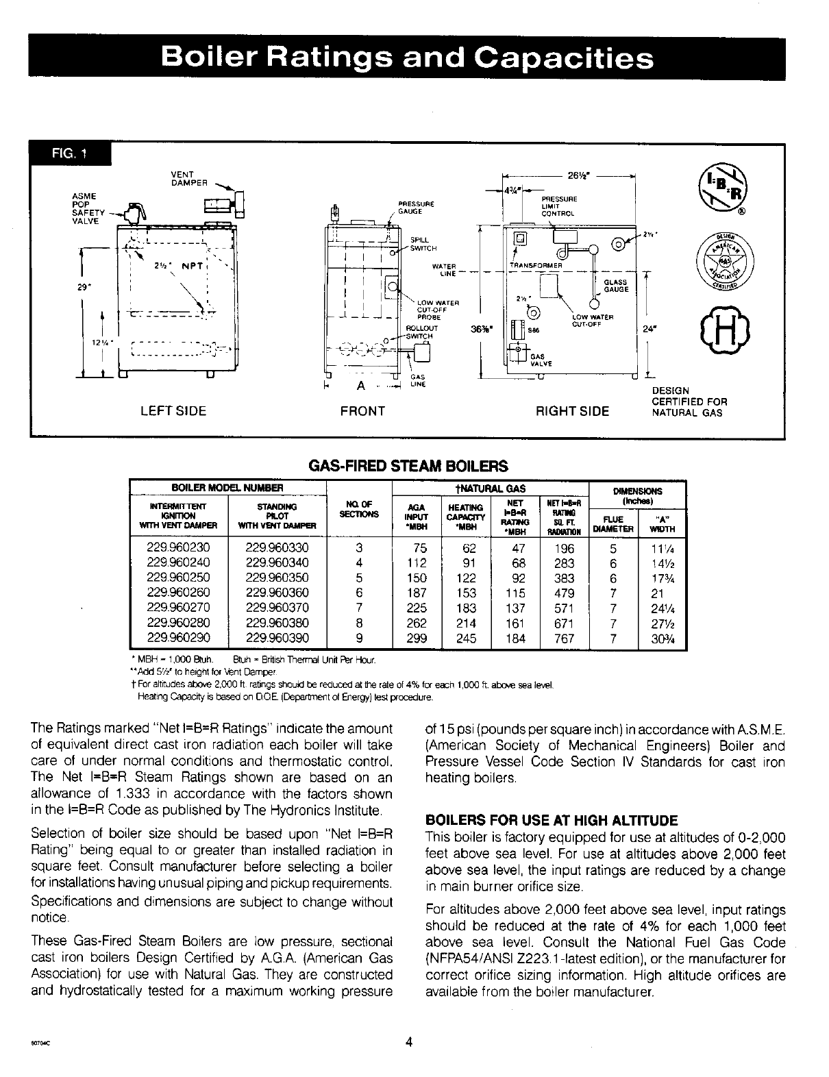
75 62 47 196 5 111_
112 91 68 283 6 14V_
150 122 92 383 6 !7¾
187 153 115 479 7 21
225 183 137 571 7 24%
262 214 161 67! 7 2_/_
299 245 184 767 7 303/4
*MBH = 1,000 8tuh. Btuh = British Tnermat Unit Per Hour
**Add 5Vz"to height for Vent Damper
1"For altitudes above 2,000 ft rabngs should be reduced a[ the rate of 4% fc_ each 1,000 ft above sea level
Heating Capacity is based on DOE. (Department of Energy) test prc_edure
The Ratings marked "Net I=B=R Ratings" indicate the amount
of equivalent direct cast iron radiation each boiler will take
care of under normal conditions and thermostatic control.
The Net I=B=R Steam Ratings shown are based on an
allowance of 1.333 in accordance with the factors shown
in the I=B=R Code as published by The Hydronics Institute.
Selection of boiler size should be based upon "Net I--E_R
Rating" being equal to or greater than installed radiation in
square feet. Consult manufacturer before selecting a boiler
for installations having unusual piping and pickup requirements,
Specifications and dimensions are subject to change without
notice.
These Gas-Fired Steam Boilers are low pressure, sectional
cast iron boilers Design Certified by A.G.A. (American Gas
Association} for use with Natural Gas. They are constructed
and hydrostatically tested for a maximum working pressure
of 15 psi (pounds per square inch) in accordance with A.S.M.E.
(American Society of Mechanical Engineers) Boiler and
Pressure Vessel Code Section IV Standards for cast iron
heating boilers.
BOILERS FOR USE AT HIGH ALTITUDE
This boiler is factory equipped for use at altitudes of 0-2,000
feet above sea level. For use at altitudes above 2,000 feet
above sea level, the input ratings are reduced by a change
in main burner orifice size.
For altitudes above 2,000 feet above sea level, input ratings
should be reduced at the rate of 4% for each 1,000 feet
above sea level. Consult the National Fuel Gas Code
(NFPA54/ANSl Z223.1 -latest edition}, or the manufacturer for
correct orifice sizing information. High altitude orifices are
available from the boiler manufacturer.
r_7_c 4
Checkto besureyouhavetherightsizeboilerbeforestartingtheinstallation.
Seerating and capacitytable on previouspage. Also be sure the new
boiler is for the type of gas you are using.Checkthe ratingplate on
the rightsideof theboiler.
Youmust see that the boiler is suppliedwith the correct type of gas,
fresh air for combustion,anda suitableelectricalsupplyAlso,the boiler
mustbe connectedto a suitablechimneyandanadequatepipingsystem.
Finallya thermostat,properlylocated,is neededfor controlof the heating
system.If you haveany doubtsas to the variousrequirements,check
with local authoritiesand obtain professionalhetp whereneeded.Take
the time to completeall of the steps for SAFEand PROPERoperation
of the heatingsystem.
Theseboilersare designedfor use in closedheatingsystemswhereall
of the steam is returnedto the boiler as condensateand the amount
of make-upwater requiredis minimal.Theseboilers are not designed
for or intendedfor use in opensystemsor processapplicationsusing
I
100%make-upwater.Damageto the boilerresultingfrom suchuse shall
not becoveredunderthewarranty
Whererequiredby the authorityhavingjurisdiction,the installationmust
conformto AmericanSocietyof MechanicalEngineersSafetyCode for
ControlsandSafetyDevicesfor AutomaticallyFiredBoilers,No.CSD-1.
The installationmus_conformto the requirementsof the authorityhaving
jurisdictionor, in the absenceof suchrequirements,to the NationalFuel
GasCode,ANSIZ223.1-1atestrevision.
Thefollowingstepsareallnecessaryforproperinstallationandsafeoperation
ol yourboiler.
1. LOCATINGTHEBOILER 5. GASSUPPLYPIPING
2. FRESHAIRFORCOMBUSTION 6. ELECTRICALWIRING
3. INSTALLATION- SYSTEMPIPING 7. CHECKING& ADJUSTING
4. CHIMNEY& VENTPIPECONNECTION
KEEP BOILER AREA CLEAN AND FREE FROM COMBUSTIBLE MATERIALS,
GASOLINE AND OTHER FLAMMABLE VAPORS AND LIQUIDS
1. Selectlevel locationas centralizedwith pipingsystem,and as near
chimney,aspossible.
2. Placecratedboilerat selectedlocation,removecrateby pullingcrate
sidesfrom top and bottom boards.Combustiblefloors:Whenboiler
is to be installedon a combustiblefloor,a SpecialBasePlatemust
beused- 146-14-031(3-6 Section}or 146-14-032(7-9 Section}.
Thisboilermustnotbe installedon carpeting.
3. If this boiler is equippedwith cast iron burners,it is also equipped
with stainlesssteel wire ties to hold the backend of the cast iron
burnersin placeduringshipping.In orderto removethe burnersfor
cleaningor inspection,the wire ties must be cut andremoved.The
wire ties are accessedthroughthe combustionair openingon the
backside of the boiler at the bottom of the rearjacket panel,and
maybe cut with any wire cutting pliers. I1the boileris installedat
its minimumclearancesit maybe difficultto reachthe wireties after
the boileris installed,and lhe wire ties shouldbe cut now.Thewire
tiesareonlyneededduringshipping,anddo not needto bereplaced.
Boilersequippedwith stainlesssteel burnersdo nothavewire
ties andthis informationdoesnotapply.
4. Boiler is to be level.Metalshimsmaybe used underbaselegs for
finalleveling.
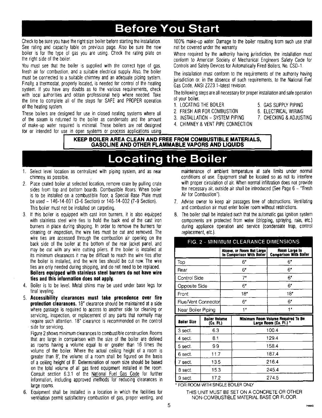
5. Accessibility clearances must take precedence over fire
protectionclearances.18"clearanceshouldbe maintainedat a side
wherepassageis requiredto accessto anotherside for cleaningor
servicing,inspection,or replacementof any partsthat normallymay
requiresuchattention.18" clearanceis recommendedon the control
sidefor servicing.
Figure2showsminimumclearancesto combustibleconstruction.Rooms
thatare largein comparisonwith the size of the boiler are defined
as rooms havinga volumeequal to or greater than 16 times the
volumeof the boiler. Wherethe actualceiling heightof a room is
greaterthan 8', the volumeof a roomshaft be figuredon the basis
of a ceilingheighto18'. Determinationof roomsizeshouldbe based
on the total volumeof air gas fired equipmentinstalledin the room.
Consuttsection 6.3.1 of the NationalFuel Gas Code for further
information,includingapprovedmethodsfor reducingclearancesin
largerooms.
6. Equipmentshall be installedin a locationin which the facilitiesfor
ventilationpermitsatisfactorycombustionof gas,properventing,and
maintenanceof ambient temperatureat safe limits under normal
conditionsof use.Equipmentshall be locatedso as not to interfere
withpropercirculationof air.Whennormalinfiltrationdoesnot provide
thenecessaryair,outsideairshallbeintroduced(SeePage6 - "Fresh
Airfor Combustion").
7. Adviseownerto keep air passagesfree of obstructions.Ventilating
andcombustionairmustenterboilerroomwithoutrestrictions.
8. Theboilershallbeinstalledsuchthattheautomaticgasignitionsystem
componentsare protectedfrom water(dripping,spraying,rain, etc.)
during applianceoperationand service (condensatetrap, control
replacement,etc.).
Top
Rear
Control Side
Opposite Side
Front
Flue/Vent Connecto_
Near Boiler Piping
BoilerVolume
(Cu.Ft.)
63
8!
99
11.7
13.5
153
17.2
BoilerSize
3 sect.
4 sect.
5 sect.
6 sect.
7 sect.
8 sect.
9 sect.
Alcove,orRoomNMLarge
InComparisonWithBoiler
6'
6' 6*
7' 6*
6' 6'
18" 18'
6" 6"
1" 1"
MinimumRoomVolumeRequiredToBe
LargeRoom(Cu.Ft.)*
100.4
129.4
158.4
187.4
216,4
245.4
274,5
RoomLargeIn
ComparisonWithBoiler
6'
*FORROOMWITHSINGLEBOILERONLY
THIS UNIT MUST BE SET ON A CONCRETE OR OTHER
NON-COMBUSTIBLE MATERIAL BASE OR FLOOR.
Provision for combustion and ventilation air must be in accordance with Section 5.3, Air for Combustionand
Ventilation, of the National Fuel Gas Code, ANSI Z223.1-1atest revision, or applicable provisions of the local building codes.
WARNING
Be sure to provide enough freshair for combustion.
Enoughair insuresproper combustionand assuresthat
no hazardwilldevelopdueto the lackof oxygen.
You must provide for enough fresh air to assure proper
combustion. The fire in the boiler uses oxygen. It must have
a continuous supply. The air in a house contains only enough
oxygen to supply the burner for a short time. Outside air
must enter the house to replace that used by the burner.
Study following examples 1 and 2 to determine your fresh
air requirements,
EXAMPLE 1: Boiler Located in Unconfined Space
If your boiler is in an open area (unpartitioned basement)
in a conventional house, the air that leaks through the cracks
around doors and windows will usually be adequate to provide
air for combustion. The doors should not fit tightly. Do not
caulk the cracks around the windows,
An unconfined space is defined as a space whose volume
is not less than 50 cubic feet per 1,000 Btu per hour of
the total input rating of all appliances installed in that space.
EXAMPLE 2: Boiler Located in Confined Space
A. All Air from Inside the Building: The confined space
shall be provided with two permanent openings
communicating directly with an additional room(s) of
sufficient volume sothat the combined volume of all spaces
meets the criteria for an unconfined space. The total input
of all gas utilization equipment installed in the combined
space shall be considered in making this determination.
Each opening shall have a minimum free area of one
square inch per 1,000 Btu per hour of the total input rating
of all gas utilization equipment in the confined space, but
not less than 100 square inches. One opening shall be
within 12 inches of the top and one within 12 inches of
the bottom of the enclosure,
B, All Air from Outdoors: The confined space shall be
provided with two permanent openings, one commencing
within 12 inches of the top and one commencing within
12 inches of the bottom of the enclosure. The openings
shall communicate directly, or by ducts, with the outdoors
or spaces (crawl or attic) that freely communicate with
the outdoors.
1. When directly communicating with the outdoors, each
opening shall have a minimum free area of one square
inch per 4,000 Btu per hour of total input rating of alt
equipment in the enclosure.
NOTE
If you use a fireplace or a kitchen or bathroom exhaust
fan, you should install an outside air intake. These devices
will rob the boiler and water heater of combustion air.
2. When communicating with the outdoorsthrough vertical
ducts, each opening shall have a minimum free area
of one square inch per 4,000 Btu per hour of total
input rating of all equipment in the enclosure.
3. When communicating with the outdoors through
horizontal ducts, each opening shall have a minimum
free area of one square inch per 2,000 Btu per hour
of total input rating of all equipment in the enclosure.
4. When ducts are used, they shall be of the same cross-
sectional area as the free area of the openings to which
they connect. The minimum dimension of rectangular
air ducts shall be not less than three inches.
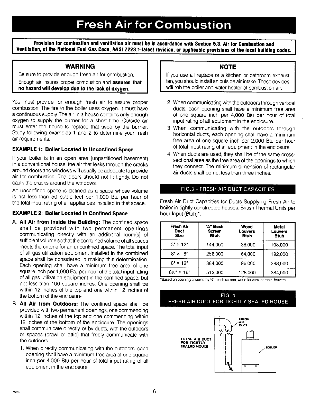
Fresh Air Duct Capacities for Ducts Supplying Fresh Air to
boiler in tightly constructed houses. British Thermal Units per
hour Input (Btuh)*.
Fresh Air 1/,- Mesh Wood Metal
Duct Screen Louvers Louvers
Size Btuh Btuh Btuh
3' x 12' 144,000 36,000 108,000
8" x 8' 256,000 64,000 192,000
8' x 12" 384,000 96,000 288,000
8V2' x 16' 512,000 128,000 384,000
*Basedon opening covered by V4"meshscreen,woodIouvers,ormetallouvers.
FRESH AIR DUCT
FOR TIGHTLY
SEALED HOUSE
FRESH
AIR
DUCT
,_,* 6
The near boiler piping, that is the piping around the boiler,
must be considered as part of the boiler for proper water
level control, and to produce dry steam. Correct near boiler
piping is crucial to the proper operation of the boiler and
the heating system. Follow these recommendations carefully
1 Place boiler in selected location, as near chimney as
possible.
2. Install the pop safety valve, using the furnished 3/4"
coupling, into the 3/4' pipe nipple on the top of the boiler.
Make a discharge pipe, using 3/4' pipe (not furnished}
to carry the water or steam to a nearby drain. Do not
connect the discharge pipe directly to a drain but leave
an air gap. The downstream end of the discharge pipe
must be unthreaded. No shutoff of any description shall
be placed between the pop safety valve and the boiler,
,
4.
or on discharge pipes between such safety valves and
the atmosphere. Installation of the pop safety valve shall
conform to the requirements of the ANSI/ASME Boiler and
Pressure Vessel Code, Section IMThe manufacturer is not
responsible for any water damage
This boiler is equipped with two 2V2' supply connections
and two 2V2" return connections, one each on both the
left and right sides of the boiler. Unused connections must
be plugged with the 2V2" plugs (furnished}
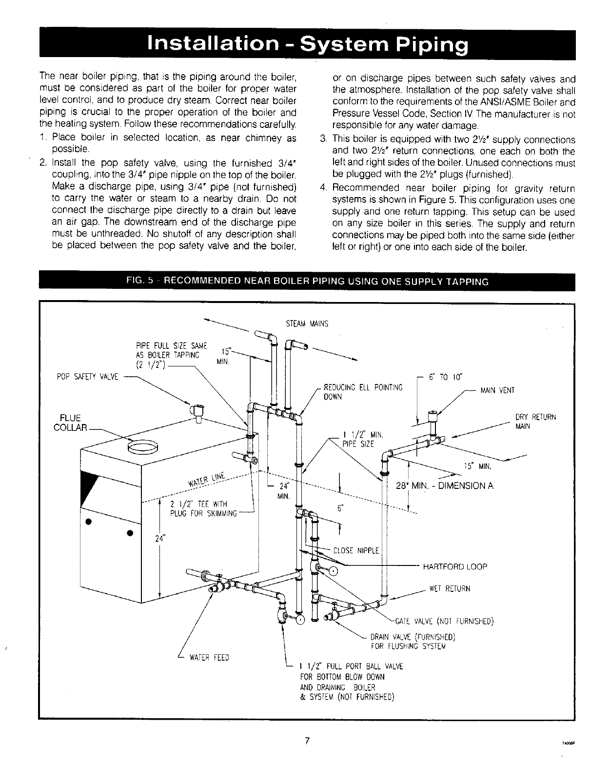
Recommended near boiler piping for gravity return
systems is shown in Figure 5. This configuration uses one
supply and one return tapping. This setup can be used
on any size boiler in this series. The supply and return
connections may be piped both into the same side (either
left or right} or one into each side of the boiler.
PiPEFULLSIZESAME
ASBOILERTAPPING
(2
POPSAFETYVALVE
FLUE
2 1/2" TEEWITH
PLUGFOR
24"
JFEED
STEAMMAINS
-REDUCINGELL POINTING
DOWN
6" TO 10"
11/2" MIN
PIPESIZE
15" MIN.
28' MIN - DIMENSIONA
NIPPLE
)RD LOOP
WETRETURN
-GATE VALVE(NOT FURNISHED)
_" DRAINVALVE(FURNISHED)
FOR FLUSHING SYSTEM
I 1/2" FULL PORT BALL VALVE
FOR BOTTOMBLOWDOWN
AND DRAINING BOILER
& SYSTEM(NOT FURNISHED)
MAINVENT
DRYRETURN
MAIN
7,_
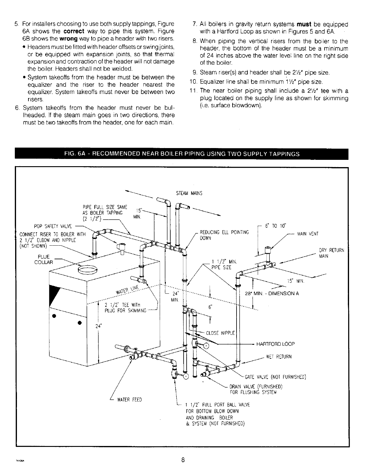
5. For installers choosing to use both supply tappings, Figure
6A shows the correct way to pipe this system. Figure
6B shows the wrong way to pipe a header with two risers.
• Headers must be fitted with header offsets or swing joints,
or be equipped with expansion joints, so that thermal
expansion and contraction of the header will not damage
the boiler. Headers shall not be welded.
• System takeoffs from the header must be between the
equalizer and the riser to the header nearest the
equalizer. System takeoffs must never be between two
risers.
6. System takeoffs from the header must never be bul-
lheaded. If the steam main goes in two directions, there
must be two takeoffs from the header, one for each main.
7. All boilers in gravity return systems must be equipped
with a Hartford Loop as shown in Figures 5 and 6A.
8. When piping the vertical risers from the boiler to the
header, the bottom of the header must be a minimum
of 24 inches above the water level line on the right side
of the boiler.
9. Steam riser(s) and header shall be 2V2" pipe size.
10. Equalizer line shall be minimum iV2" pipe size.
11. The near boiler piping shall include a 21/2, tee with a
plug located on the supply line as shown for skimming
{i.e. surface blowdown).
PIPEFULLSIZESAN_E
AS BOILERTAPPING
(2 1/2"
POP SAFETYVALVE
CONNECTRISERTO BOILERWITH
2 I/2"ELBOW AND NIPPLE
(NOTSHOWN)
FLUE
COLLAR
MIN
2 1/2" TEEWITH
PLUGFOR
@ 24"
W_AfERFEED
STEAM MAINS
ELLPOINTING
DOWN
1 1/2" MIN.
PIPESIZE
NIPPLE
6" TO 10"
MAINVENT
DRY RETURN
MAIN
1S" MIN.
28" MIN DIMENSIONA
HARTFORD LOOP
RETURN
-GATEVALVE(NOTFURNISHED)
_ORAIN VALVE(FURNISHED)
FOR FLUSHINGSYSTEM
I I/2"FULLPORT BALLVALVE
FOR BOTFOM BLOW DOWN
AND DRAININGBOILER
& SYSTEM(NOTFURNISHED)
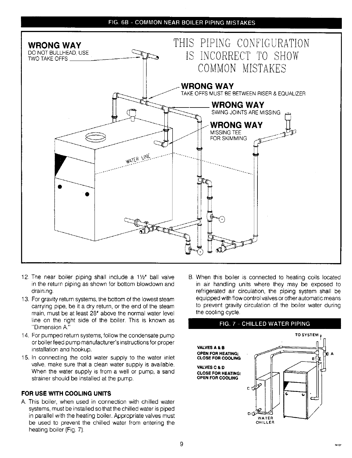
WRONG WAY
DO NOT BULLHEAD,USE
TWO TAKEOFFS
THIS PIPING CONFIGURATION
IS INCORRECTTO SHOW
COMMONMISTANES
WRONG WAY
TAKE OFFS MUST BE BETWEEN RISER & EQUALIZER
WRONG WAY
SWING JOINTS ARE MISSING
)NG WAY
MISSING TEE
FOR SKIMMING
12. The near boiler piping shall include a 1V2" ball valve
in the return piping as shown for bottom blowdown and
draining.
13. For gravity return systems, the bottom of the lowest steam
carrying pipe, be it a dry return, or the end of the steam
main, must be at least 28' above the normal water level
line on the right side of the boiler. This is known as
"Dimension A."
14. For pumped return systems, follow the condensate pump
or boiler feed pump manufacturer's instructions for proper
installation and hookup.
15. In connecting the cold water supply to the water inlet
valve, make sure that a clean water supply is available.
When the water supply is from a well or pump, a sand
strainer should be installed at the pump.
FOR USE WITH COOLING UNITS
A. This boiler, when used in connection with chilled water
systems, must be installed so that the chilled water is piped
in parallel with the heating boiler. Appropriate valves must
be used to prevent the chilled water from entering the
heating boiler (Fig. 7).
B. When this boiler is connected to heating coils located
in air handling units where they may be exposed to
refrigerated air circulation, the piping system shall be
equipped with flow control valves or other automatic means
to prevent gravity circulation of the boiler water during
the cooling cycle.
VALVES A & B
OPEN FOR HEATING;
CLOSE FOR COOLING
VALVES C & D
CLOSE FOR HEATING:
OPEN FOR COOLING
TO SYSTEM t
C
O
CHILLER
_4_o7
IFor boilers for connection to gas vents or chimneys, vent installations shall be I
In accordance with Part 7, VenUng of Equipment, of the National Fuel Gas Code, IANSI Z223.1-1atest revision and applicable provisions of the local building codes.
CHECK YOUR CHIMNEY
This is a very important part of your heating system. It must
be clean, the right size, properly constructed and in GOOD
CONDITION. No boiler can function properly with a bad chim-
ney Inspect the chimney and verify that the construction and
size of the chimney meets all applicable provisions of the
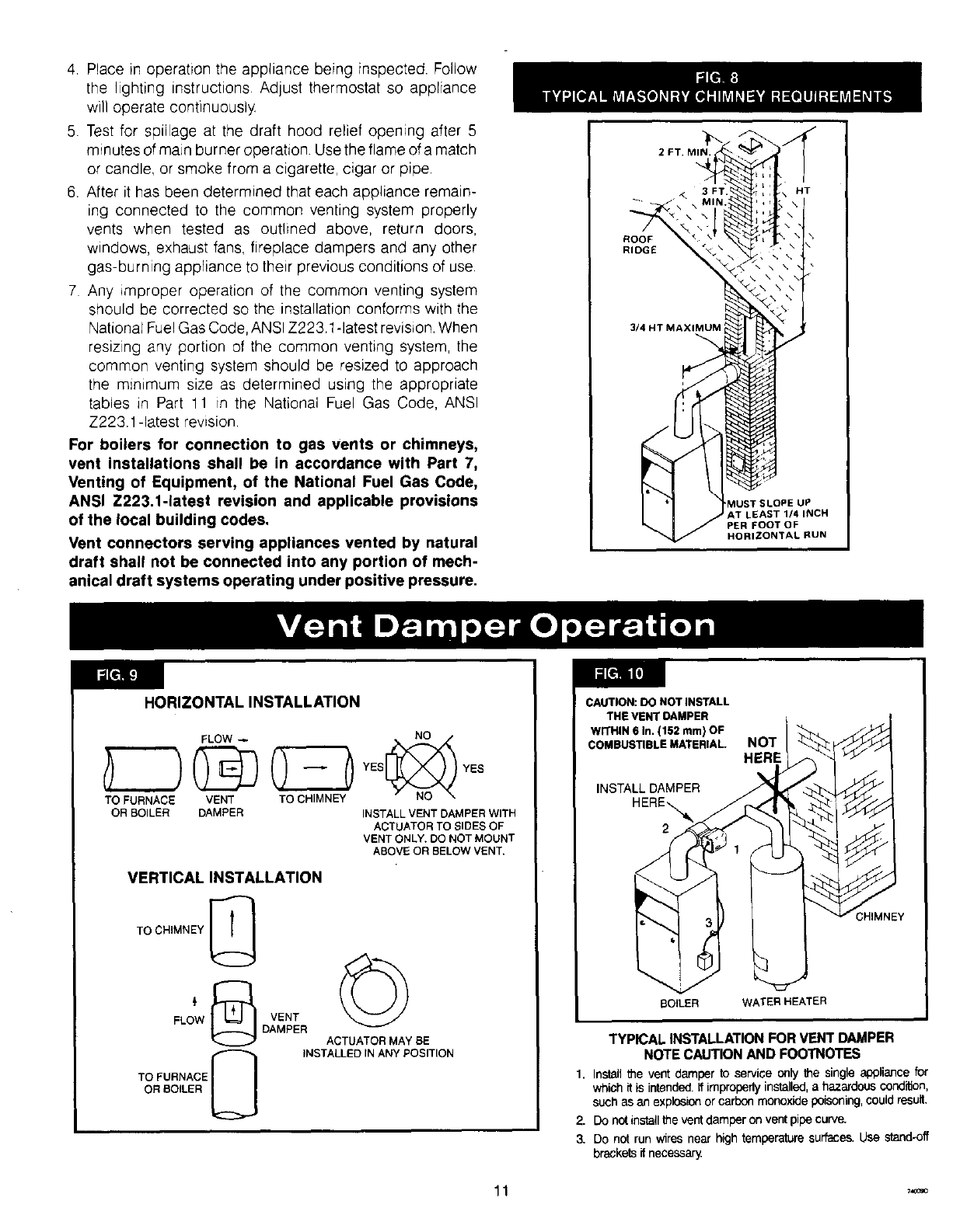
National Fuel Gas Code and local building codes. Fig. 8
gives you an idea how a boiler might be vented to a chimney.
Note that the height (HT) is measured from the vent pipe
to the top.
CHIMNEY SIZING
Chimney sizing and all other aspects of the vent installation
must be in accordance with Part 7 of the National Fuel Gas
Code, ANSI Z223.1-latest revision, and applicable provisions
of the local building codes.
CONNECTING THE VENT DAMPER
AND VENT CONNECTOR
Refer to Fig. 1 flue diagram for the size and location of the
vent (flue opening). Use a 28 gauge (minimum) galvanized
pipe to connect to the chimney
IMPORTANT - The damper blade on the furnished vent
damper has a 1/2square inch hole (approximately 3A,diame-
ter). On boilers equipped with standing pilot, the hole must
be left open. On boilers equipped with intermittent ignition,
the hole should be plugged by using the plug supplied with
the vent damper.
1. Position furnished vent damper on top of flue outlet collar,
Fasten damper securely to flue outlet collar with sheet
metal screws. Make sure damper blade has clearance
to operate inside of diverter.
As An Option
The damper may be installed in any horizontal or vertical
position, closer to the flue outlet collar preferred. Follow
the diagrams - Figures 9, 10 and 11.
2. Install the vent damper to service only the single boiler
for which it is intended. The damper position indicator
shall be in a visible location following installation. Locate
the damper so that it is accessible for servicing.
3. The damper must be in the open position when appliance
main burners are operating.
4. The boiler is equipped with a factory wired harness that
plugs into the vent damper. The thermostat must be
connected to the black wires marked 24 volt thermostat
on the boiler.
5. Vent pipe must be same size as the flue outlet collar.
6. Slope pipe up from boiler to chimney not less than V4'
per foot.
7. Run pipe as directly as possible with as few elbows as
possible.
8. Do not connect to fireplace flue.
9. End of vent pipe must be flush with inside face of chimney
flue. Use a sealed-in thimble for the chimney connection.
10. Horizontal run should not be longer than 3Athe chimney
height (HT) (Fig. 8).
The sections of vent pipe should be fastened with sheet metal
screws to make the piping rigid. Horizontal portions of the
vent system must be supported to prevent sagging. Use
stovepipe wires every 5' to support the pipe from above.
If the vent pipe must go through a crawl space, double wall
vent pipe should be used. Where vent pipe passes through
a combustible wall or partition, use a ventilated metal thimble,
The thimble should be 4 inches larger in diameter than the
vent pipe.
MINIMUM VENT PIPE CLEARANCE
Wood and other combustible materials must not be closer
than 6' from any surface of single wall metal vent pipe. Listed
Type B vent pipe or other listed venting systems shall be
installed in accordance with their listing.
REMOVING EXISTING BOILER FROM
COMMON VENTING SYSTEM
When an existing boiler is removed from a common venting
system, the common venting system is likely to be too large
for proper venting of the appliances remaining connected
to it.
At the time of removal of an existing boiler, the following
steps shall be followed with each appliance remaining
connected to the common venting system placed in operation,
while the other appliances remaining connected to the
common venting system are not in operation.
1,
2.
Seal any unused openings in the common venting system.
Visually inspect the venting system for proper size and
horizontal pitch and determine there is no blockage or
restriction, leakage, corrosion and other deficiencies which
could cause an unsafe condition.
,Insofar as is practical, close all building doors and windows
and all doors between the space in which the appliances
remaining connected to the common venting system are
located and other spaces of the building. Turn on clothes
dryers and any appliance not connected to the common
venting system. Turn on any exhaust fans, such as range
hoods and bathroom exhausts, so they will operate at
maximum speed. Do not operate a summer exhaust fan.
Close fireplace dampers.
,,_ 10
4 Placeinoperationtheappliancebeinginspected.Follow
the lightinginstructions.Adjustthermostatsoappliance
willoperatecontinuousl_z
5. Testfor spillageatthedrafthoodreliefopeningafter5
minutesofmainburneroperation.Usetheflameofamatch
orcandle,orsmokefromacigarette,cigarorpipe
6. Afterit hasbeendeterminedthateachapplianceremain-
ing connectedto thecommonventingsystemproperly
ventswhen testedas outlinedabove,returndoors,
windows,exhaustfans,fireplacedampersandanyother
gas-burningappliancetotheirpreviousconditionsofuse
7 Any_mproperoperationof thecommonventingsystem
shouldbecorrectedsotheinstallationconformswiththe
NationalFuelGasCode,ANSIZ223.1-latestrevision.When
resizinganyportionof thecommonventingsystem,the
commonventingsystemshouldbe resizedto approach
the m_n_mumsizeas determinedusingtheappropriate
tablesin Part11 in the NationalFuelGasCode,ANSI
Z223.1-latestrewsion.
For boilers for connection to gas vents or chimneys,
vent installations shall be in accordance with Part 7,
Venting of Equipment, of the National Fuel Gas Code,
ANSI Z223.1-1atest revision and applicable provisions
of the local building codes,
Vent connectors serving appliances vented by natural
draft shall not be connected into any portion of mech-
anical draft systems operating under positive pressure.
ROOF
RIDGE
3/4 HT MAXIMUM
HT
MUST SLOPE UP
AT LEAST 1/4 INCH
PER FOOT OF
HORIZONTAL RUN
HORIZONTAL INSTALLATION
TO FURNACE VENT TO CHIMNEY
OR BOILER DAMPER INSTALL VENT DAMPER WITH
ACTUATOR TO SIDES OF
VENT ONLY, DO NOT MOUNT
ABOVE OR BELOW VENT.
VERTICAL INSTALLATION
TO CHIMNEY [_
FLOW VENT
DAMPER ACTUATOR MAY BE
TO FURNACE N INSTALLED IN ANY POSITION
OR BOILER U
TYPICAL INSTALLATION FOR VENT DAMPER
NOTE CAUTION AND FOOTNOTES
1. Install the vent damper to service only the single appliance for
which it is intended,ff improperlyinstalled,ahazardous condition,
such as an explosion or carbon monoxide poisoning, could result.
2. Do not install the vent damper on vent pipe curve.
3. DO not run wiras near high temperature surfaces. Use stand-off
brackets it necessary
For safe, efficient operation, the vent damper and all flue
product carrying areas of the appliance must be checked
annually by you, with particular attention given to deterioration
from corrosion or other sources. If you see corrosion or other
deterioration, contact your heating contractor for repairs.
Check vent damper operation as follows:
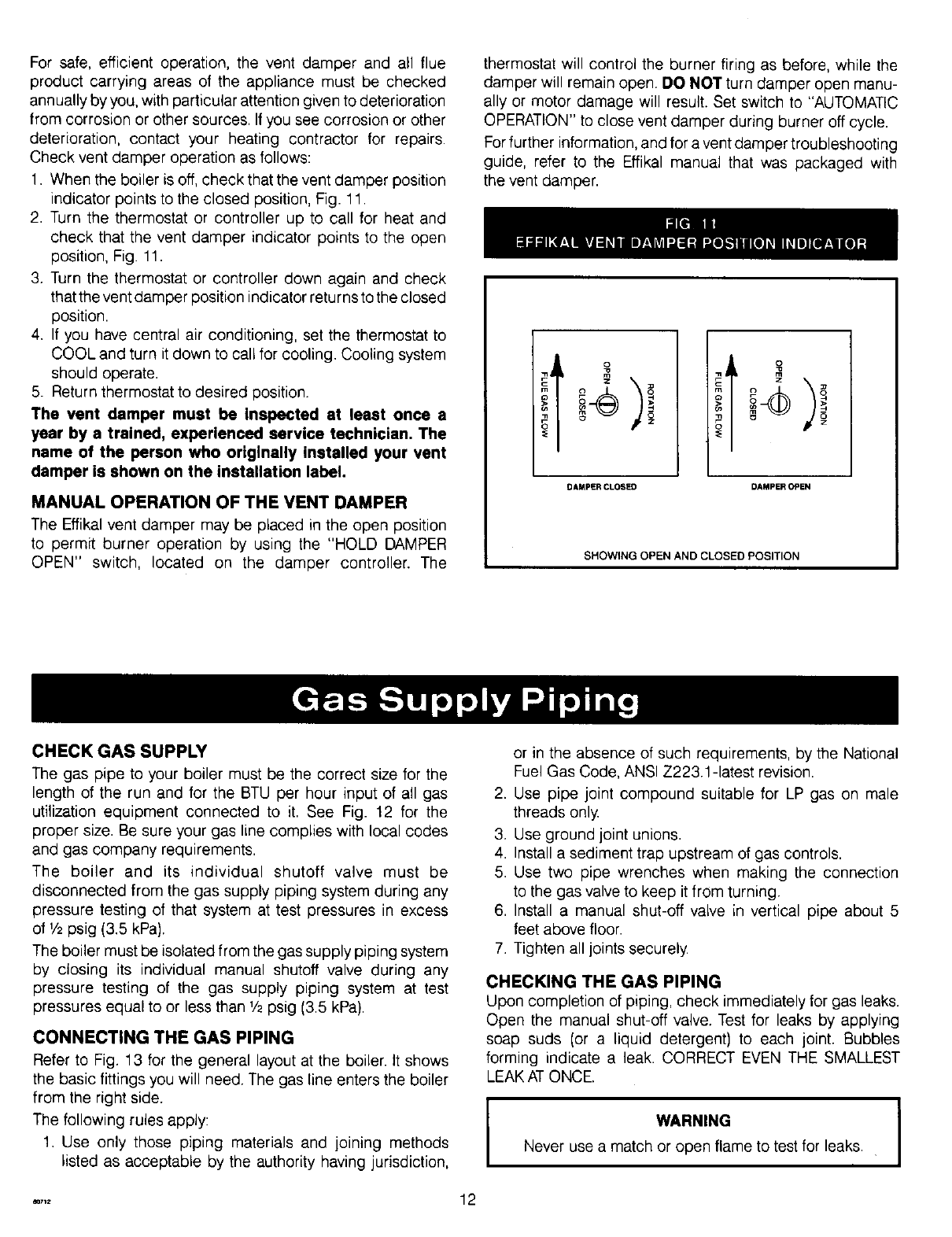
1. When the boiler is off, check that the vent damper position
indicator points to the closed position, Fig. 11.
2. Turn the thermostat or controller up to call for heat and
check that the vent damper indicator points to the open
position, Fig. 11.
3. Turn the thermostat or controller down again and check
that the vent damper position indicator returns to the closed
position.
4. If you have central air conditioning, set the thermostat to
COOL and turn it down to call for cooling. Cooling system
should operate.
5. Return thermostat to desired position.
The vent damper must be Inspected st least once a
year by a trained, experienced service technician, The
name of the person who originally installed your vent
damper is shown on the installation label.
MANUAL OPERATION OF THE VENT DAMPER
The Effikal vent damper may be placed in the open position
to permit burner operation by using the "HOLD DAMPER
OPEN" switch, located on the damper controller. The
thermostat will control the burner firing as before, while the
damper will remain open. DO NOT turn damper open manu-
ally or motor damage will result. Set switch to "AUTOMATIC
OPERATION" to close vent damper during burner off cycle.
For further information, and for a vent damper troubleshooting
guide, refer to the Effikal manual that was packaged with
the vent damper.
iI
DAMPER CLOSED DAMPER OPEN
SHOWING OPEN AND CLOSED POSITION
CHECK GAS SUPPLY
The gas pipe to your boiler must be the correct size for the
length of the run and for the BTU per hour input of all gas
utilization equipment connected to it. See Fig. 12 for the
proper size. Be sure your gas line complies with local codes
and gas company requirements.
The boiler and its individual shutoff valve must be
disconnected from the gas supply piping system during any
pressure testing of that system at test pressures in excess
of V2psig (3.5 kPa).
The boiler must be isolated from the gas supply piping system
by closing its individual manual shutoff valve during any
pressure testing of the gas supply piping system at test
pressures equal to or less than V2psig (3.5 kPa).
CONNECTING THE GAS PIPING
Refer to Fig. 13 for the general layout at the boiler. It shows
the basic fittings you will need. The gas line enters the boiler
from the right side.
The following rules apply:
1. Use only those piping materials and joining methods
listed as acceptable by the authority having jurisdiction,
or in the absence of such requirements, by the National
Fuel Gas Code, ANSI Z223.1-latest revision.
2. Use pipe joint compound suitable for LP gas on male
threads only.
3. Use ground joint unions.
4. Install a sediment trap upstream of gas controls.
5. Use two pipe wrenches when making the connection
to the gas valve to keep it from turning.
6. Install a manual shut-off valve in vertical pipe about 5
feet above floor.
7. Tighten all joints securely
CHECKING THE GAS PIPING
Upon completion of piping, check immediately for gas leaks.
Open the manual shut-off valve. Test for leaks by applying
soap suds (or a liquid detergent) to each joint. Bubbles
forming indicate a leak. CORRECT EVEN THE SMALLEST
LEAK AT ONCE.
WARNING 1Never use a match or open flame to test for leaks.
.... 12
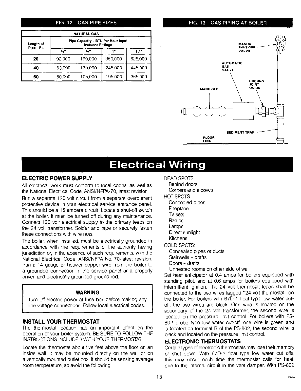
NATURAL GAS
Pipe Capactty- BTU Per Hourlnput
Length of Includes Fittings
Pipe - Ft. ½" ¾" 1" 1%"
20 92,000 190,000 350,000 625,000
40 63,000 130,000 245,000 445,000
60 50,000 ! 05,000 195,000 365,000
MANUAL
SHUT-OFF
VALVE
AUTOMATIC
VALVE
GROUND
JOINT
MANIFOLD UNION
S OI.ENTTRAP pl
FLOOR
LINE _u
ELECTRIC POWER SUPPLY
All electrical work must conform to local codes, as well as
the National Electrical Code, ANSI/NFPA-70, latest revision.
Run a separate 120 volt circuit from a separate overcurrent
protective device in your electrical service entrance panel.
This should be a 15 ampere circuit. Locate a shut-off switch
at the boiler. It must be turned off during any maintenance.
Connect 120 volt electrical supply to the primary leads on
the 24 volt transformer. Solder and tape or securely fasten
these connections with wire nuts.
The boiler, when installed, must be electrically grounded in
accordance with the requirements of the authority having
jurisdiction or, in the absence of such requirements, with the
National Electrical Code, ANSI/NFPA No. 70-latest revision.
Run a 14 gauge or heavier copper wire from the boiler to
a grounded connection in the service panel or a properly
driven and electrically grounded ground rod.
]WARNING
Turn off electric power at fuse box before making any
line voltage connections. Follow local electrical codes. I
INSTALL YOUR THERMOSTAT
The thermostat location has an important effect on the
operation of your boiler system. BE SURE TO FOLLOW THE
INSTRUCTIONS INCLUDED WITH YOUR THERMOSTAT.
Locate the thermostat about five feet above the floor on an
inside wall. It may be mounted directly on the wall or on
a vertically mounted outlet box. It should be sensing average
room temperature, so avoid the following:
DEAD SPOTS:
Behind doors
Corners and alcoves
HOT SPOTS:
Concealed pipes
Fireplace
TV sets
Radios
Lamps
Direct sunlight
Kitchens
COLD SPOTS:
Concealed pipes or ducts
Stairwells - drafts
Doors - drafts
Unheated rooms on other side of wall
Set heat anticipator at 0.4 amps for boilers equipped with
standing pilot, and at 0.6 amps for boilers equipped with
intermittent ignition. The 24 volt thermostat leads shall be
connected to the two wires tagged "24 volt thermostat" on
the boiler. For boilers with 67D-1 float type low water cut-
off, the two wires are black. One wire is located on the
secondary of the 24 volt transformer, the second wire is
located on the pressure limit control. For boilers with PS-
802 probe type low water cut-off, one wire is green and
is located on terminal B of the PS-802, the second wire is
black and located on the pressure limit control.
ELECTRONIC THERMOSTATS
Certain types of electronic therrnostats may lose their memory
or shut down. With 67D-! float type low water cut offs,
this may occur each time the thermostat calls for heat,
due to the internal circuit in the vent damper. With PS-802
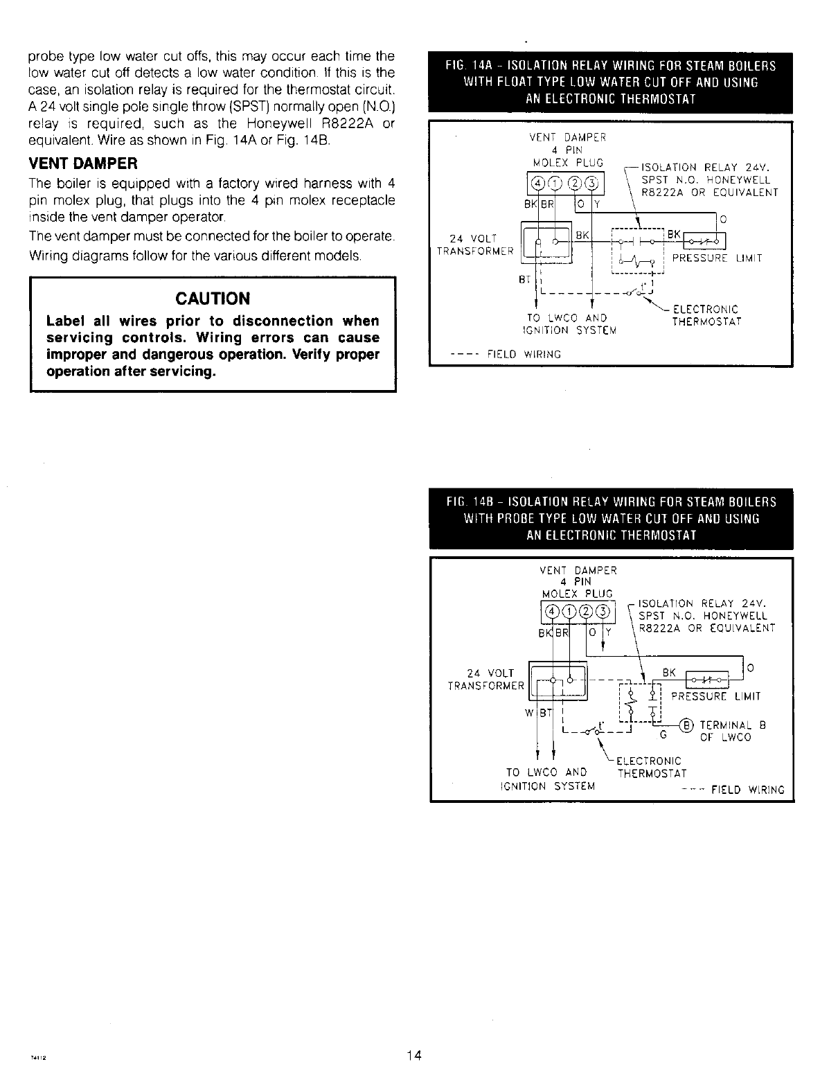
probetypelowwatercutotis,thismayoccureachtimethe
lowwatercutoffdetectsa lowwaterconditionIfthisisthe
case,anisolationrelayis requiredforthethermostatcircuit
A24voltsinglepolesinglethrow(SPST)normallyopen(N.O.)
relay _srequired,such as the HoneywellR8222Aor
equivalent.WireasshowninFig.14AorFig.14B.
VENT DAMPER
The boiler is equipped with a factory wired harness with 4
pin molex plug, that plugs into the 4 pin molex receptacle
inside the vent damper operator.
The vent damper must be connected for the boiler to operate.
Wiring diagrams follow for the various different models.
CAUTION
Label all wires prior to disconnection when
servicing controls. Wiring errors can cause
improper and dangerous operation, Verify proper
operation after servicing.
24 VOLT
TRANSFORMER
VENT DAMPER
4 PLN
MOLEX PLUG
TO LWCO AND
IGNITION SYSTEM
-ISOLATION RELAY 24V.
SPST N+O. HONEYWELL
Y I R8222A OR EQUIVALENT
' !O
,_-----t----IBK
]_,_? i PRESSURE LIMIT
L........ p.J
.... .+tJ
%\ ELECTRONIC
THERMOSTAT
.... FIELD WLRING
VENT DAMPER
4 PIN
MOLEX PLUG
BK
24 VOLT r_
TRANSFORMER L_
7
TO LWCO AND
IGNITION SYSTEM
_y _-ISpOs[TATI?o ' REoLNAYyW22EV L
R8222A OR EQUIVALENT
°
+ ++ __±,,",PRES_ LIMIT
L-," TERMINAL++
-o"o--- G OF LWCO
_- ELECTRONIC
THERMOSTAT
--- FIELD WLRING
..... 14
_ -- WIRE NUT
COLOR CODE
8K-BIJ_CK
BR-BROWN
0 -ORA_C£
y-_AA_OW
R-RED
BT-BIJ_CN WITH TRACER
W -11_41rE
G -GRE[]_
8-BLUE
EFFIKAL RVGP VENT OA,_PER
MOLEX PLUG
I 15V/BOHZ/I f L_
pOWER B_X
SUPPLY
r-l_ \/
j\®/.....
L_ _____.j'--"
OP_ONAL WF-2U-2_.
WATi_
_"l{EOER
NOTE:T_¼1N_. N0 ] APpFJ_R$ ONLy
ON WATER FEEC_R MODELS WITH
tJXNL_I. _£0 PUSH 8U_'ON.
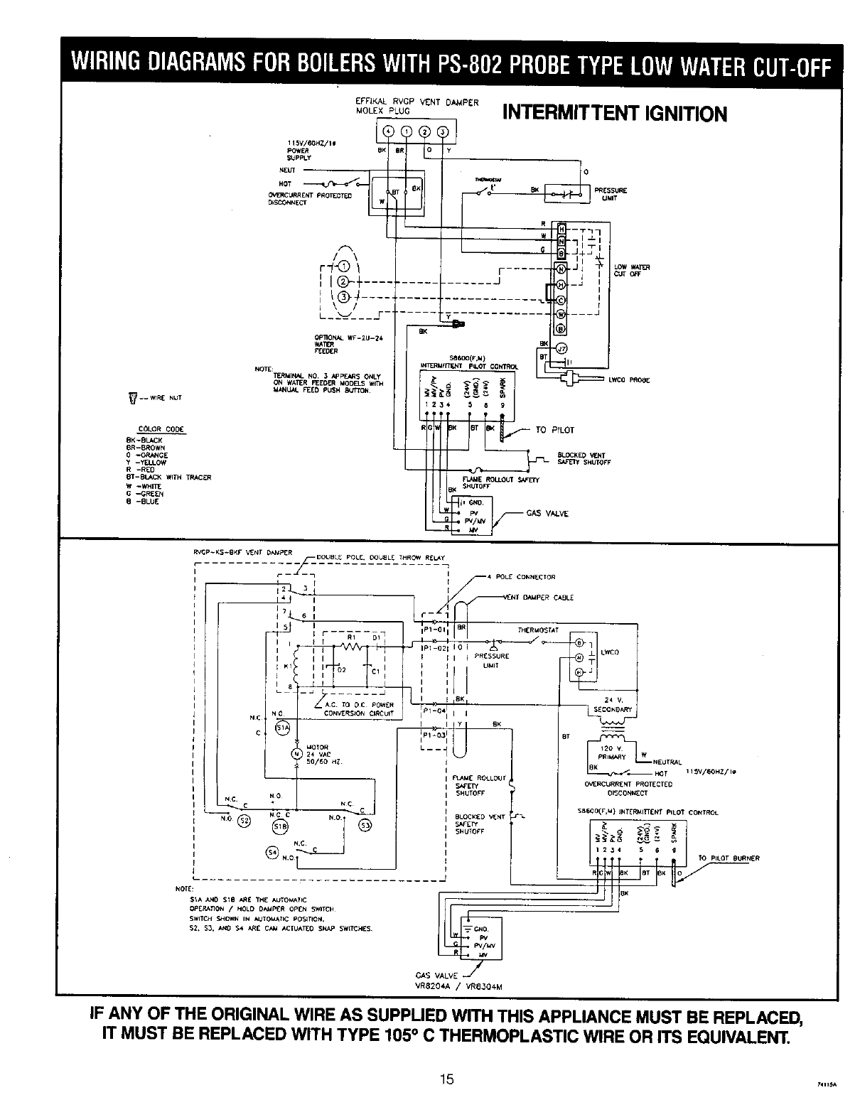
INTERMITTENT IGNITION
) _
iiii
_LWC 0 pRoBEWt_RMRTF'NT pIL'OT CONTRCt
RTO PrLOT
SAP_ SHUTOFF
AI_V[
VR8204A /VR8304M
IF ANY OF THE ORIGINAL WIRE AS SUPPLIED WITH THIS APPLIANCE MUST BE REPLACED,
IT MUST BE REPLACED WITH TYPE 105° C THERMOPLASTIC WIRE OR ITS EQUIVALENT.
15 7411_
_--WIRE NUT
HeVI_OHZllm i (
pOW_ 8K
SUpPLy
.T
_SO3NNECT _
A
',IQ-÷ .......
I_@-4
L_X=/___J- .....
COLOR CODE
8X-B_
BR-E_ROWN
0-ORANGE OPI1ONAL _-2U--:14
y-YELLOW W_TER
R-RED REED_
BT-B_ VCh'H TRACER NOTE:
W-WHITE
G-GREEN TERMIteS. NO, 3 APpF_S C_NLY
8-BLUE ON WATER F_ER MOC_'LS
MANUAL BEF.,D PUSH t_,rrTON
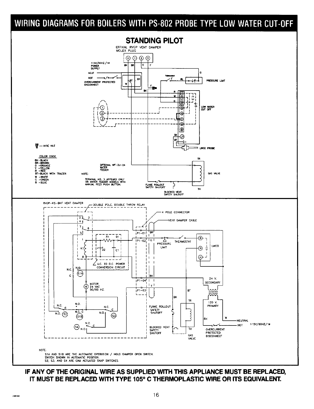
STANDING PILOT
EFFIKAL RVGP V_NT DAMPER
MOLEX PLUG
)@(
Y
r ......
J
PRESSURE UMIT
I
I
I
RVGP-KS-BKF VENT OA._PER OOUBL_ POLE, DOUBLE THROW RELAy
II 4POLE CONNECrOR
/-;
NC
C
N.C.
II
12_._? I
i7J-_6 I
15_15 I
.... _2 J
A.C. TO D.C POWER
). CONVERSION CIRCUIT
,3-
MOTOR
_2 4 VAC
50/60 HZ
N'O N.C,
N,C, C
®..o.__-___J
PI_osTAT
LIMI T LWCO
1_ 24 V.
_1-0411yll
FLA_E ROLLOUT
SHUTOFF
_ N[UT_ L
BLOCKED _NT HOT
S_E_ O_RCURRENT
SHUTOFF PROTECT[D
GAS DISCONNECT
VAL_
i1_V/BOHZ/I_
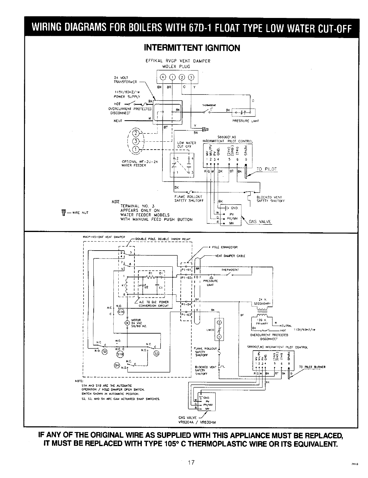
NOTE:
SlA AND SlB ARE THE AUTOk_T_C Op[RATJON / HOLD BAMPER OPEN SWITCH
SWITCH SHOWN tN AUTOMATICPOSLTION.
$2, $3. AND S4 ARE CAXt ACTUATEDSNAP SV_TCHES
IF ANY OF THE ORIGINAL WIRE AS SUPPLIED WITH THIS APPLIANCE MUST BE REPLACED,
IT MUST BE REPLACED WITH TYPE 105 ° C THERMOPLASTIC WIRE OR ITS EQUIVALENT.
I_-- WIRE NUT
INTERMITTENT IGNITION
24 VOLT
TRANSFORMER
115V/BOHZ/I_ %
POWER SUPPLY
.oT-_Jo-._
0V£RCURRENT PROTECTED
DISCONNECT
W
NEUT
\)
\(_ .....
OPTIONAL WF-2U-24
WAFER FEEDER
NOTE:
TERMINAL NO. 3
APPEARS ONLY ON
WATER FEEDER MODELS
WITH MANUAL FEED PUSH BUTTON
EFFIKAL RVGP VENT DAMPER
MOLEX PLUG
pR_SSURC LIMIT
FLAME ROLLOUI T
GAS VALVE
RVCp-KS-BKF V,ENT O_IpzR
"i_ ZNr DAtaPER C_.81E
I7II r
_ _6 I --
isi...... 'p._L"o,1 r.ER'_OS,^T
Kt r r _ Ll_Ir
°," ,'
-- i YBK _
o D ,°'-°",1I S2j'a-_
( _°,fv°_ _--i L# I ;2_;, I.
50/60 HZ. 8K N_UIRAL
LWC0 _ _HO T115'V/60HZ/ II_
NC N0 Nj
.-% .o1o
kOTD
SlA A_O SIB _g THE AUT0_TIC
OPg_TrON /HIN_ _I_R OPEN NTCH
S,N_TCH SHNH IN _OMATIC POSmI_.
_FFPr
5NUIOFF
BLOCKED _T
SV_"ET_
SHUTOFF
cAs
VRB204A /VR8304M
OV£RCURRENI PROT[CTED
DISCORNECT
S8600(F,M) INI[RUlTT[N_ PILOI CONTROL
>>>Z _" N _.
1234 S 6 g
TTO pILOt BURN£R
IF ANY OF THE ORIGINAL WIRE AS SUPPLIED WITH THIS APPLIANCE MUST BE REPLACED,
IT MUST BE REPLACED WITH TYPE 105 ° C THERMOPLASTIC WIRE OR ITS EQUIVALENT.
1 7 741_3
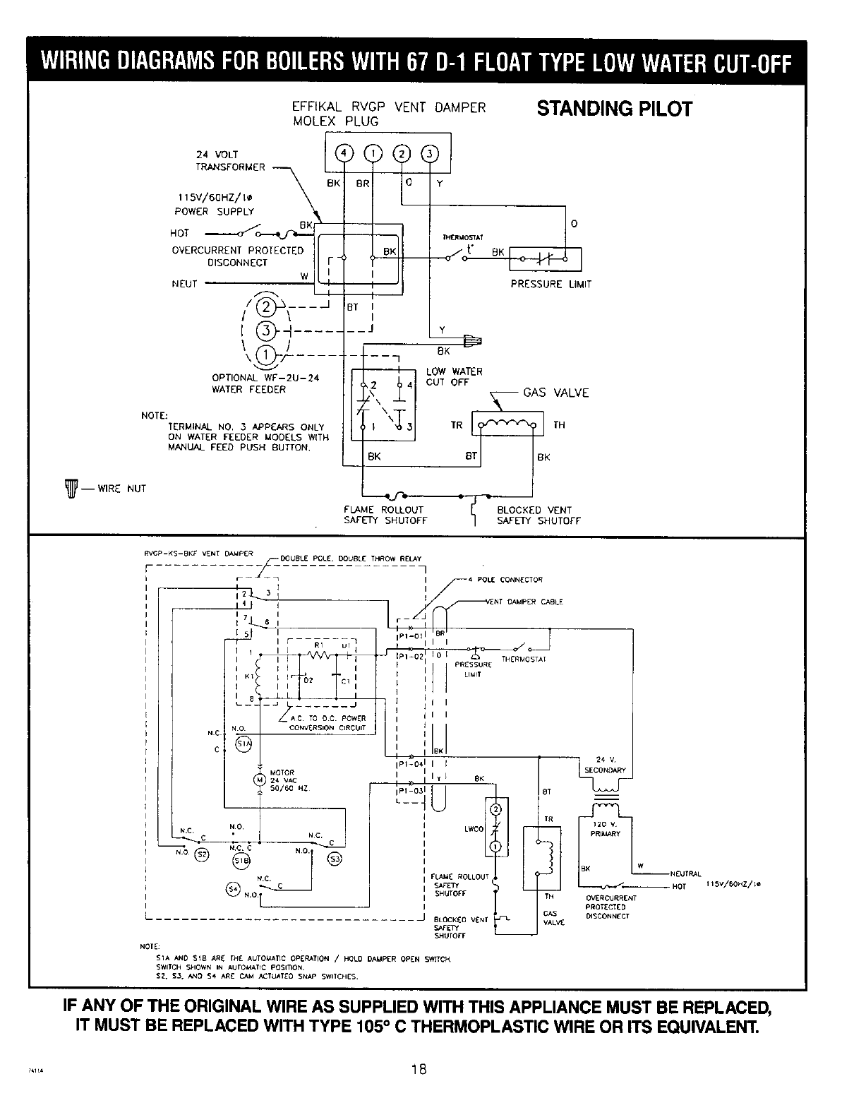
EFFIKAL RVGP VENT DAMPER STANDING PILOT
MOLEX PLUG
NOTE:
I_ -- WIRE NUT
24 VOLT
TRANSFORMER
IIBV/6OHZ/I¢
POWER SUPPLY
HOT ._----_--_
OVERCURRENT PROTECTED
DISCONNECT
W
NEUT
OPTIONAL WF-2U-24
WATER FEEDER
TERMINAL NO. 3 APPEARS ONLY
ON WATER FEEDER MODELS WITH
MANUAL FEED PUSH BUTTON.
PRESSURE LIMIT
BT I
I
J y
BK
FLAME ROLLOUT
SAFETY SHUTOFF
LOW WATER
CUT OFF
_ VALVE
TR T_ TH
B K
BLOCKED VENT
SAFETY SHUTOFF
RVCp-KS-BKF V_NT OA._pER
TO OC. POWER
CONVERSION CIRCUIT
NC
C
IP1-03
NOTE:
S1A AND SIB ARE THE AUTO,TIC OPERATION /HOL0 DAMPER OPEN SWITCH¸
SWITCH SHOWN IN AUrO_:ATIC POSITION¸
$2. $3. Nq0 $4 ARE CAM ACTUATEDSN_o SWITCHES.
IF ANY OF THE ORIGINAL WIRE AS SUPPLIED WITH THIS APPLIANCE MUST BE REPLACED,
IT MUST BE REPLACED WITH TYPE 105 ° C THERMOPLASTIC WIRE OR ITS EQUIVALENT.
..... 18
POP SAFETY VALVE
The pop safety valve should open automatically if the boiler
steam pressure exceeds the pressure rating of the valve (15
psig). Should it ever fail to open under this condition, shut
down your boiler. If valve discharge occurs, or valve fails
to open as described above, contact an authorized contractor
or qualified service technician to replace the pop safety valve
and inspect the heating system to determine the cause, as
this may indicate an equipment malfunction.
Run a p_pe from the safety valve outlet (pipe must be same
size as outlet and open end must not be threaded) to an
open drain, tub or sink, or other suitable drainage point not
subject to freezing. Failure to do so may cause Water damage
or injury should relief valve release Do not cap off the drain
line from this valve!
STEAM PRESSURE GAUGE
Every system should have a pressure gauge installed in the
boiler. This gauge enables you to monitor the pressure in
the system. If the safety devices fail to shut off your boiler
at the proper settings, notify your serviceman immediately
WATER LEVEL GAUGE
The water level in the boiler can be seen through the glass
tube in the water level gauge at side of boiler. Correct cold
boiler water revel is stamped on side jacket panel. The water
level should be checked regularly for the proper level.
On the right side jacket panel of the boiler, there are three
holes for the glass water level gauge. The top hole is common
for both types of low water cut off, and is used for the upper
gauge glass fitting. The middle hole, 9" down from the top
hole, is used for the bottom gauge glass fitting for the Model
67D-1 and 47-2 float type low water cut off. The lowest hole,
12V4" down from the top hole, is used for the bottom gauge
glass fitting for the Model PS-802 probe type low water cut
off. The hole that is not being used is covered with a sheet
metal knockout.
STEAM PRESSURE CONTROL
The steam pressure limit control {pressuretrol) shuts off the
gas to the main burners when the steam pressure in the
boiler reaches the cut-off setpoint (i.e. the sum of the cut-
in and the differential setpoints). Burners retire when the steam
pressure drops to the cut-in setpoint. System pressure
requirements are based on the size and condition of the
pipes, and the load.
LOW WATER CUT-OFF
1Model 67D-1
This is a float operated switch which shuts down the gas
burner if water falls below the visible bottom of the gauge
glass.
2. Model PS-802
This is an electronic probe type LWCO. The probe is
located inside the boiler. The LWCO will shut down the
burners if the water loses contact with the probe for a
period of 10 seconds.
Refer to manufacturer's instructions {enclosed) for more
information.
WATER FEEDER (Optional)
The Model WF-2U-24 water feeder may be used with either
of the available low water cut-offs. The water feeder's job
is to maintain a safe minimum water level It's used to
keep the boiler running by compensating for minor
evaporative steam leaks, and to prevent freeze-ups if the
homeowners are away and a return line should spring
a leak.
McDonnell and Miller Model 101 water feeders may be
used, however the water feed rates are too high and need
to be regulated or throttled, and wiring will have to be
revised. Consult the boiler manufacturer before using these
or any other non-standard types of controls.
The automatic water feeder is a safety device, not a
convenience item. It is not designed to maintain a "normal"
water line. The water feeder does not take the place of
a responsible person monitoring and maintaining the
normal water line. Steam boilers require personal attention.
VENT DAMPER
This is an automatic, motorized stack damper that has
been developed to increase the efficiency of heating
systems by reducing standby losses from the boiler end
the conditioned air space. The damper closes the chimney
vent when the burner is off and fully opens it when
combustion is required.
ROLLOUT SWITCH
(FLAME ROLLOUT SAFETY SHUTOFF)
The rollout switch is a temperature-sensitive fuse link
device. It is located on the boiler base just outside the
fire box. In the event of heat exchanger flueway blockage
causing flame to roll out of the fire box, the fuse will blow,
shutting down the flow of gas to the main burners. The
fuse does not change in appearance when blown.
If the rollout switch blows, it must be replaced with an
exact replacement. Check heat exchanger flueways for
blockage when restoring system to operating condition.
Do not operate system without a rollout switch.
SPILL SWITCH
(BLOCKED VENT SAFETY SHUTOFF)
The spill switch is a manual reset disc thermostat with
a fixed setpoint (280 °F), and normally closed contacts.
It is located at the relief opening of the draft diverter. In
the event of chimney or venting system blockage causing
products of combustion to spill out of the relief opemng,
the spill switch disc heats up and the spill switch contacts
will open, shutting down the flow of gas to the main burners
by removing power to the gas valve.
In the event that the spill switch contacts open, the reset
button on the back of the switch will pop up. The spill
switch must be reset manually, after the switch has cooled
off, by pushing the reset button down. Check the venting
system and chimney for blockage when restoring the
system to operating condition. DO NOT operate the boiler
without a spill switch.
1 9 7_ISH
WARNING: If you do not follow these instructions exactly, a fire or explosion
may result causing property damage, personal injury or loss of life.
A. Some boilers are equipped with an intermittent ignition
device which automatically lights the pilot. Do not try to
light the pilot by hand.
Some boilers are equipped with a continuous pilot and
must be manually lighted. (See lighting instructions on page
17.) A match holder is included in the parts bag.
B. BEFORE OPERATING smell all around the appliance area
for gas. Be sure to smell next to the floor because some
gas is heavier than air and will settle on the floor.
WHAT TO DO IF YOU SMELL GAS
• Do not try to light any appliance.
• Do not touch any electric switch; do not use any phone
in your building.
C.
E_
• Immediately call your gas supplier from a neighbor's
phone. Follow the gas supplier's instructions.
•If you cannot reach your gas supplier, call the fire
department.
Use only your hand to push in or turn the gas control
knob. Never use tools. If the knob will not push in or turn
by hand, don't try to repair it, call a qualified service
technician. Force or attempted repair may result in a fire
or explosion.
Do not use this appliance if any part has been under
water. Immediately call a qualified service technician to
inspect the appliance and to replace any part of the control
system and any gas control which has been under water.
1. STOP! Read the safety information on this page.
2. Set the thermostat to lowest setting.
3. Turn off al! electric power to the appliance.
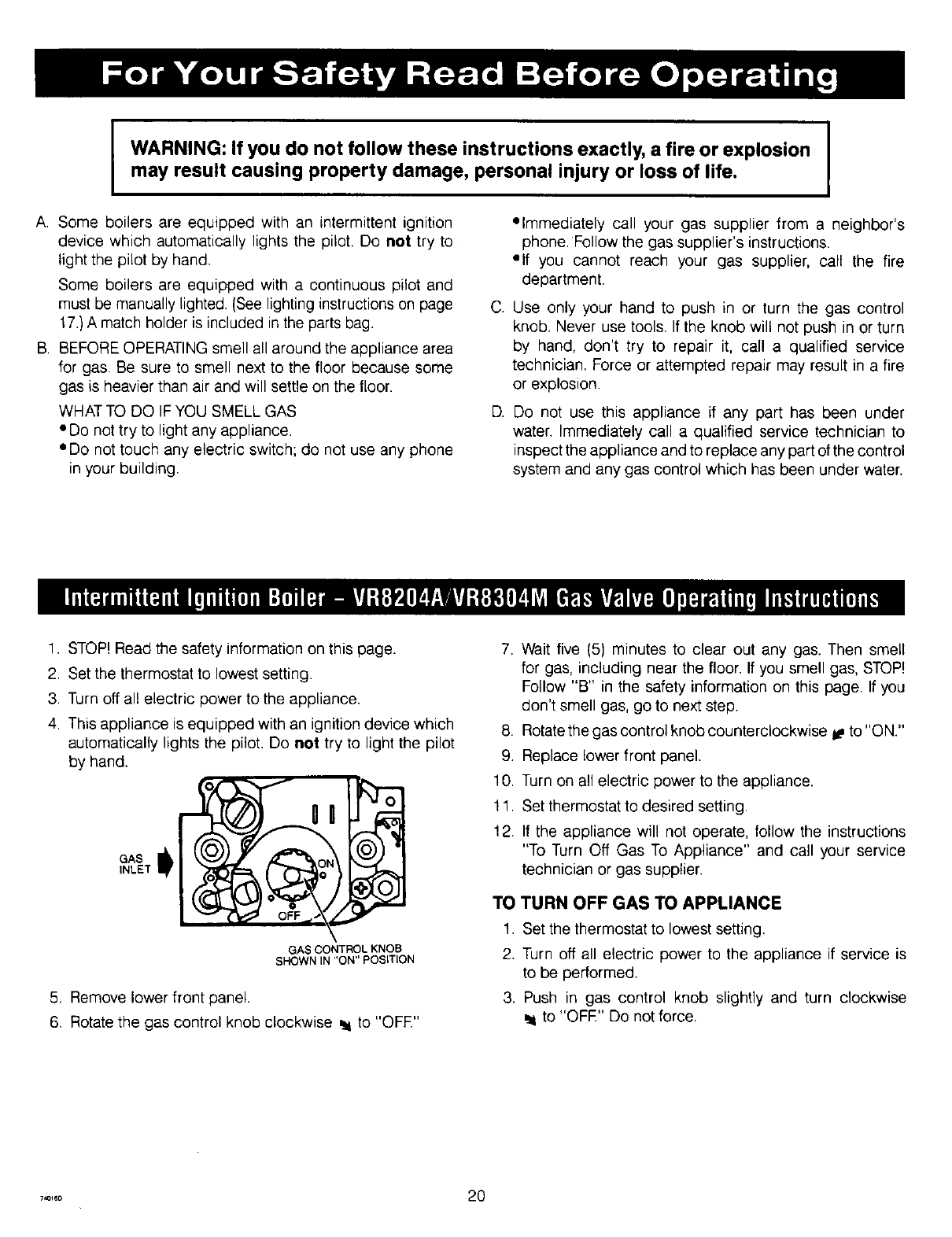
4. This appliance is equipped with an ignition device which
automatically lights the pilot. Do not try to light the pilot
by hand.
GAS
INLET |
GAS CONTROL KNOB
SHOWN IN "ON" POSITION
5. Remove lower front panel.
6. Rotate the gas control knob clockwise _ to "OFE"
7. Wait five (5) minutes to clear out any gas. Then smell
for gas, including near the floor. If you smell gas, STOP!
Follow "B" in the safety information on this page. If you
don't smell gas, go to next step.
8. Rotate the gas control knob counterclockwise I# to "ON."
9. Replace lower front panel.
10. Turn on all electric power to the appliance.
11. Set thermostat to desired setting.
12. If the appliance will not operate, follow the instructions
"To Turn Off Gas To Appliance" and call your service
technician or gas supplier.
TO TURN OFF GAS TO APPLIANCE
1. Set the thermostat to lowest setting.
2. Turn off all electric power to the appliance if service is
to be performed.
3. Push in gas control knob slightly and turn clockwise
to "OFE" Do not force.
..... 20
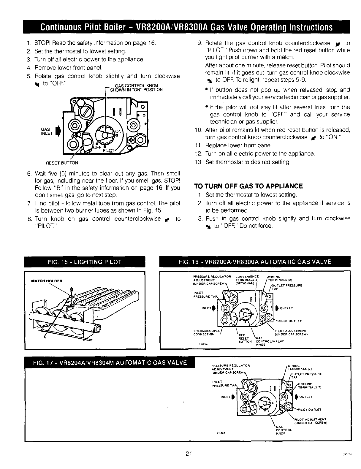
1. STOP!Readthesafetyinformationonpage16.
2. Setthethermostatto lowestsetting.
3. Turnoffallelectricpowertotheappliance.
4. Removelowerfrontpanel.
5. Rotategas controlknob slightlyand turn clockwise
to GAS CONTROL KNOB
[-SHOWN IN "ON" POSITION
/
GAS
INLET
• O
RESET BUTTON
6. Wait five (5) minutes to clear out any gas. Then smell
for gas, including near the floor. If you smell gas, STOP!
Follow "B" in the safety information on page 16. If you
don't smell gas, go to next step.
7. Find pilot - follow metal tube from gas control. The pilot
is between two burner tubes as shown in Fig. 15.
8. Turn knob on gas control counterclockwise _ to
"PILOT"
9 Rotate the gas control knob counterclockwise _, to
"PILOT" Push down and hold the red reset button while
you light pilot burner with a match.
After about one minute, re[ease reset button. Pilot should
remain lit If it goes out, turn gas control knob clockwise
to OFE To relight, repeat steps 5-9.
•If button does not pop up when released, stop and
immediately call your service technician or gas supplier.
•If the pilot will not stay lit after several tries, turn the
gas control knob to "OFF" and call your service
technician or gas supplier.
10. After pilot remains lit when red reset button is released,
turn gas control knob counterclockwise _ to "ON."
1!. Replace lower front panel.
12. Turn on all electric power to the appliance.
13 Set thermostat to desired setting.
TO TURN OFF GAS TO APPLIANCE
1. Set the thermostat to lowest setting.
2. Turn off all electric power to the appliance if service is
to be performed.
3. Push in gas control knob slightly and turn clockwise
_i to "OFE" Do not force.
MATCH HOLDER
P_ESSUR( R£GULATOR CONVENIENCE WIRING
ADJUSTMENT TERMINAl{2} TERMINAL3 (2)
{UNDERpRESSUREINLETCAPTApSCREW)_I_i_(OPTION_L} OAUpTLET PRESSURE
;,:LoToU*L'T
THERMOCOUP OT ADJUSTt'_E NT
CONNECTION . 'RREEN \GA S (UNDER CAP SCREW)
BUTTON CONTROL/VALVE
11,523A KNOll
PRESSUR_R{GULATOR
A_JUSTMENT
(UNDER CAP SCREW)
PRESSURETA_
INLET
WIRING
TERMINALS(3)
OUTLETPRESSUR£
TAP
GROUNO
TERMCNAL$(2)
.: , ;:LOTOUTL'T
OTADJ_STM_NT
{UNOERCAPSCREW)
_GA$
CONTROL
KNOE
21 7_0t 7H
HOW A STEAM SYSTEM OPERATES
The water in the boiler is heated until it reaches the boiling
point. As the water boils it turns into steam. The steam rises
from the top of the water through the supply main to the
radiation units. As it passes through the radiators it releases
its heat and condenses into water. The water returns to the
boiler through the return main. Most residential systems
operate at less than 1 pound steam pressure.
FILLING SYSTEM WITH WATER
©n steam heating systems the boiler is partially filled with
water. It is very important to the proper operation of the entire
system that your boiler be filled to the proper level. The correct
water level is about halfway up the glass water level gauge
as marked on the boiler jacket. To fill:
1. Close the boiler drain valve.
2. Open the valves at the top and bottom of the glass water
level gauge. Also open the drain valve at the bottom of
the gauge.
3. Open the fill valve and allow water to run into the boiler.
J WARNING - Never run water into a hot empty boiler, J
4. Allow boiler to fill until water runs out the gauge drain
valve. Then close the gauge drain valve.
5. Continue to fill boiler until water reaches the indicated water
line. This is about halfway up the glass tube.
THERMOSTAT
Keep it set at a desired room temperature. If windows are
to be opened or heat is not needed, move thermostat pointer
to a lower setting.
NOTE
In the event of failure of any component, the system
will not operate or will go into safety lockout. The system
is completely self-checking On every call for heat, each
component must be functioning properly to permit
operation. On safety lockout the system has to be reset
by turning the thermostat to the lowest setting for one
minute, then back to the normal setting.
Safe lighting and other performance criteria were met with
the gas manifold and control assembly provided on the boiler
when the boiler underwent tests specified in ANSI Z21.13
- latest revision.
WATER LEVEL
The normal water level is shown on the right side of the
boiler and is 24' above the floor. The normal water level
is determined when the boiler is off and cold, i.e. when all
of the water in the system is inside the boiler and the return
piping below the water line, and everything above the water
line is air, no steam. When the boiler is making steam, the
water level win drop two to three inches below the normal
water line.
AUTOMATIC GAS VALVE
The Automatic Gas Valve opens or closes according to the
heat requirements of the thermostat and temperature limit
control. It closes if the pilot goes out. Each individual control
must be operating correctly before any gas can pass to the
burners. Any one control can hold the gas supply from burner
regardless of the demand of any other control.
..... 22
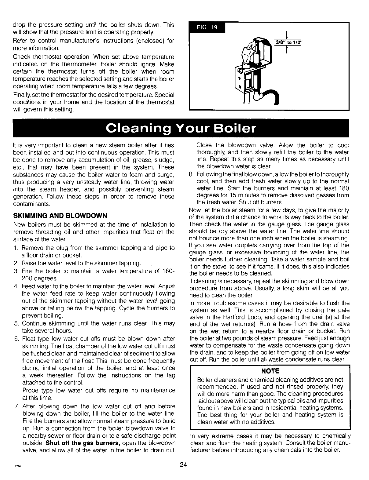
ADJUST PILOT BURNER
Pilot flame should surround 3/8' to 1/2" of the pilot sensor.
Refer to Fig. 19. If flame needs adjusting, do it as follows:
1. Remove screw cover over pilot adjusting screw.
2. Insert small screwdriver and adjust flame as needed. Turn
screw counterclockwise to increase flame, clockwise to
decrease.
3. Replace screw cover over pilot adjusting screw.
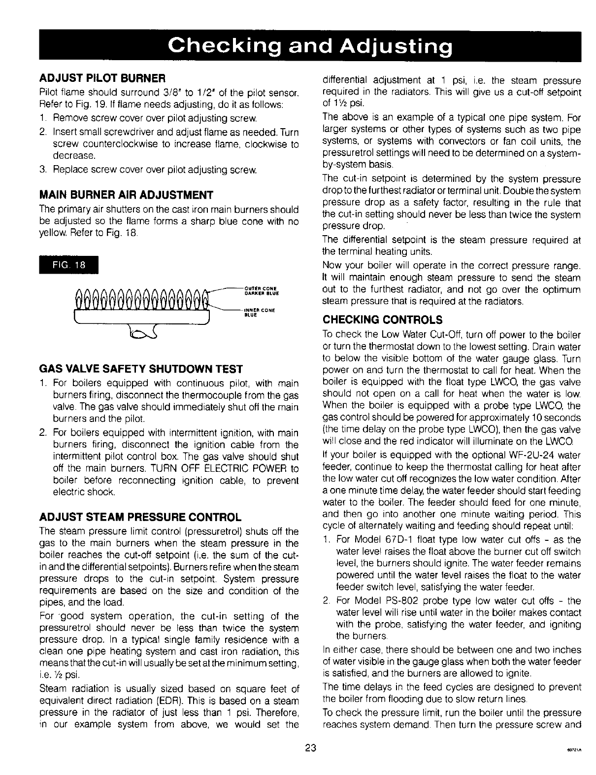
MAIN BURNER AIR ADJUSTMENT
The primary air shutters on the cast iron main burners should
be adjusted so the flame forms a sharp blue cone with no
yellow. Refer to Fig. 18.
li_[_ll i1I:]
0000@@0@0000 °°'''°°''
I_ARKIER BLUE
INNER CONE
t ) .Lo.
GAS VALVE SAFETY SHUTDOWN TEST
1. For boilers equipped with continuous pilot, with main
burners firing, disconnect the thermocouple from the gas
valve. The gas valve should immediately shut off the main
burners and the pilot.
2. For boilers equipped with intermittent ignition, with main
burners firing, disconnect the ignition cable from the
intermittent pilot control box. The gas valve should shut
off the main burners. TURN OFF ELECTRIC POWER to
boiler before reconnecting ignition cable, to prevent
electric shock.
ADJUST STEAM PRESSURE CONTROL
The steam pressure limit control (pressuretrol) shuts off the
gas to the main burners when the steam pressure in the
boiler reaches the cut-off setpoint (i.e. the sum of the cut-
in and the differential setpoints). Burners retire when the steam
pressure drops to the cut-in setpoint. System pressure
requirements are based on the size and condition of the
pipes, and the load.
For 'good system operation, the cut-in setting of the
pressuretrol should never be less than twice the system
pressure drop. In a typical single family residence with a
clean one pipe heating system and cast iron radiation, this
means that the cut-in will usually be set at the minimum setting,
i.e. 1/2psi.
Steam radiation is usually sized based on square feet of
equivalent direct radiation (EDR). This is based on a steam
pressure in the radiator of just less than 1 psi. Therefore,
in our example system from above, we would set the
differential adjustment at 1 psi, i.e. the steam pressure
required in the radiators. This will give us a cut-off setpoint
of 11/2psi.
The above is an example of a typical one pipe system. For
larger systems or other types of systems such as two pipe
systems, or systems with convectors or fan coil units, the
pressuretrol settings will need to be determined on a system-
by-system basis.
The cut-in setpoint is determined by the system pressure
drop to the furthest radiator or terminal unit. Double the system
pressure drop as a safety factor, resulting in the rule that
the cut-in setting should never be less than twice the system
pressure drop.
The differential setpoint is the steam pressure required at
the terminal heating units.
Now your boiler will operate in the correct pressure range.
It will maintain enough steam pressure to send the steam
out to the furthest radiator, and not go over the optimum
steam pressure that is required at the radiators.
CHECKING CONTROLS
To check the Low Water Cut-Off, turn off power to the boiler
or turn the thermostat down to the lowest setting. Drain water
to below the visible bottom of the water gauge glass. Turn
power on and turn the thermostat to call for heat. When the
boiler is equipped with the float type LWCO, the gas valve
should not open on a call for heat when the water is low.
When the boiler is equipped with a probe type LWCO, the
gas control should be powered for approximately 10 seconds
(the time delay on the probe type LWCO), then the gas valve
will close and the red indicator will illuminate on the LWCQ
If your boiler is equipped with the optional WF-2U-24 water
feeder, continue to keep the thermostat calling for heat after
the low water cut off recognizes the low water condition. After
a one minute time delay, the water feeder should start feeding
water to the boiler, The feeder should feed for one minute,
and then go into another one minute waiting period. This
cycle of alternately waiting and feeding should repeat until:
1. For Model 67D-1 float type low water cut offs - as the
water leve! raises the float above the burner cut off switch
level, the burners should ignite. The water feeder remains
powered until the water level raises the float to the water
feeder switch level, satisfying the water feeder,
2. For Model PS-802 probe type tow water cut offs - the
water level wil! rise until water in the boiler makes contact
with the probe, satisfying the water feeder, and igniting
the burners
In either case, there should be between one and two inches
of water visible in the gauge glass when both the water feeder
is satisfied, and the burners are allowed to ignite.
The time delays in the feed cycles are designed to prevent
the boiler from flooding due to slow return lines.
To check the pressure limit, run the boiler until the pressure
reaches system demand. Then turn the pressure screw and
3 _21A
drop the pressure setting until the boiler shuts down. This
will show that the pressure limit is operating properly
Refer to control manufacturer's instructions (enclosed} for
more information.
Check thermostat operation. When set above temperature
indicated on the thermometer, boiler should ignite. Make
certain the thermostat turns off the boiler when room
temperature reaches the selected setting and starts the boiler
operating when room temperature falls a few degrees.
Finally, set the thermostat for the desired temperature. Special
conditions in your home and the location of the thermostat
will govern this setting.
It is very important to clean a new steam boiler after it has
3/8" to 1/2"
been installed and put into continuous operation. This must
be done to remove any accumulation of oil, grease, sludge,
etc., that may have been present in the system. These
substances may cause the boiler water to foam and surge,
thus producing a very unsteady water line, throwing water
into the steam header, and possibly preventing steam
generation. Follow these steps in order to remove these
contaminants.
SKIMMING AND BLOWDOWN
New boilers must be skimmed at the time of installation to
remove threading oil and other impurities that float on the
surface of the water.
1. Remove the plug from the skimmer tapping and pipe to
a floor drain or bucket.
2. Raise the water level to the skimmer tapping.
3. Fire the boiler to maintain a water temperature of 180-
200 degrees.
4. Feed water to the boiler to maintain the water level. Adjust
the water feed rate to keep water continuously flowing
out of the skimmer tapping without the water level going
above or falling below the tapping. Cycle the burners to
prevent boiling.
5. Continue skimming until the water runs clear. This may
take several hours.
6. Float type low water cut offs must be blown down after
skimming. The float chamber of the low water cut off must
be flushed clean and maintained clear of sediment to allow
free movement of the float: This must be done frequently
during initial operation of the boiler, and at least once
a week thereafter. Follow the instructions on the tag
attached to the control.
Probe type low water cut offs require no maintenance
at this time.
7. After blowing down the low water cut off and before
blowing down the boiler, fill the boiler to the water line.
Fire the burners and allow normal steam pressure to build
up. Run a connection from the boiler blowdown valve to
a nearby sewer or floor drain or to a safe discharge point
outside. Shut off the gas burners, open the blowdown
valve, and allow all of the water in the boiler to drain out.
Close the b!owdown valve. Allow the boiler to cool
thoroughly and then slowly refill the boiler to the water
line. Repeat this step as many times as necessary until
the blowdown water is clear.
.Following the final blow down, allow the boiler to thoroughly
cool, and then add fresh water slowly up to the normal
water line. Start the burners and maintain at least 180
degrees for 15 minutes to remove dissolved gasses from
the fresh water. Shut off burners.
Now, let the boiler steam for a few days, to give the majority
of the system dirt a chance to work its way back to the boiler.
Then check the water in the gauge glass. The gauge glass
should be dry above the water line. The water line should
not bounce more than one inch when the boiler is steaming.
If you see water droplets carrying over from the top of the
gauge glass, or excessive bouncing of the water line, the
boiler needs further cleaning. Take a water sample and boil
it on the stove, to see if it foams. If it does, this also indicates
the boiler needs to be cleaned.
If cleaning is necessary, repeat the skimming and blow down
procedure from above. Usually a long skim will be all you
need to clean the boiler.
In more troublesome cases it may be desirable to flush the
system as well. This is accomplished by closing the gate
valve in the Hartford Loop, and opening the drain(s) at the
end of the wet return(s). Run a hose from the drain valve
on the wet return to a nearby floor drain or bucket. Run
the boiler at two pounds of steam pressure. Feed just enough
water to compensate for the waste condensate going down
the drain, and to keep the boiler from going off on low water
cut off. Run the boiler until all waste condensate runs clear.
NOTE
Boiler cleaners and chemical cleaning additives are not
recommended. If used and not rinsed properly, they
will do more harm than good. The cleaning procedures
laid out above will clean out the typical oils and impurities
found in new boilers and in residential heating systems.
The best thing for your boiler and heating system is
clean water with no additives.
In very extreme cases it may be necessary to chemically
clean and flush the heating system. Consult the boiler manu-
facturer before introducing any chemicals into the boiler.
,,+_ 24
Checkthewaterleveleverydayortwo.Verifythewaterlineshownby
operatingthedrainvalveonthegauge.BESURETOPANDBOTTOM
VALVESONGAUGEAREALWAYSOPENSOTHATACTUALWATERLEVEL
WILLBESHOWNATALLTIMES,
Thegaugeglassshouldbedryabovethewaterline.Thewaterlineshould
notbouncemorethanaboutoneinchwhentheboilerissteaming.If
youseewaterdropletscarryingoverthroughthetopofthegaugeglass,
orexcessivebouncingofthewaterline,theboilerneedsto be cleaned.
Followthe instructionsunder"CleaningYourBoiler."
POP SAFETY VALVE
This valveshould openautomaticallywhenthe steampressureexceeds
the safe limit (per instructionspackagedwith valve).Shouldit ever fail
to openundertheseconditions,shut downyour system.Havethe valve
replacedimmediately
LOW WATER CUT-OFF
The Low WaterCut-Offwill interruptthe electricalcurrentto the burner
whenthewaterlineinthe boilerdropsto a low level.
On float type low watercut-offs,it is very importantto keep the float
chamberfree from sediment,a conditionessenlialto dependabilityTo
keepanyaccumulationfrominterferingwithfloatactionis to "BLOWDOWN"
or flush out the control regularly.This must be donetwo to threetimes
duringthe first weekafter installationand oncea weekthereafterduring
the heatingseason.Do it whilethe boileris in operation.Firstnote water
level in gaugeglass.Open blow-off valve at bottom of control; water
will pour out, flushingawaysediment.Drain until water is clear,about
a pailful,then close valve, g waterlevel in gaugeglass has dropped,
addwaterto boilerto restorelevel.Consultlowwatercut-offmanufacturer's
instructionsincludedwithboiler.
NOTE: Openingblow-off valvechecks cut-off operationtoo. As float
drops withfalling waterlevel,burnerswill shutoff. Aftervalveis closed
andnormaloperatingconditionsarerestored,burnerswill resumefiring.
Forprobetype Low WaterCut-Offs,checkactionof the LowWaterCut-
Offmonthlyto makesureit isprovidingtheproperprotection.See"Checking
and Adjusting"on page23. Low WaterCut-0ff remoteprobesmust be
removedfor periodicinspectionandcleaning,preferablyat the beginning
of eachheatingseason.Morefrequentcleaningmaybe requiredonboilers
requiringconstantor veryfrequentadditionsof makeupwater.
BURNERS
A visualcheck of the pilot and mainburnerflamesshouldbe madeat
leastonce eachyear,preferablyat the beginningof the heatingseason.
Seepage23.
BOILER FLUE PASSAGES
Under norma]operatingconditions,with the burners properlyadjusted,
it shouldnot be necessaryto cleantheboilerflue gaspassages.However,
to assuretrouble-freeoperation,we recommendthat you havethe flue
passages,burneradjustment,andoperationof the controlscheckedonce
eachyearby a competentServiceTechnician.
Beforethestart of eachseason(or wheneversystemhasbeenshutdown
for sometime)recheckthe wholesystemfor leaks... and recheckthe
boilerandventpipefor leaks.
VENT PIPE
Theventingof thisunitis veryimportantandthepipingshouldbechecked
at leastonce a season.If the vent piping shows any sign of leaking,
replaceit immediately
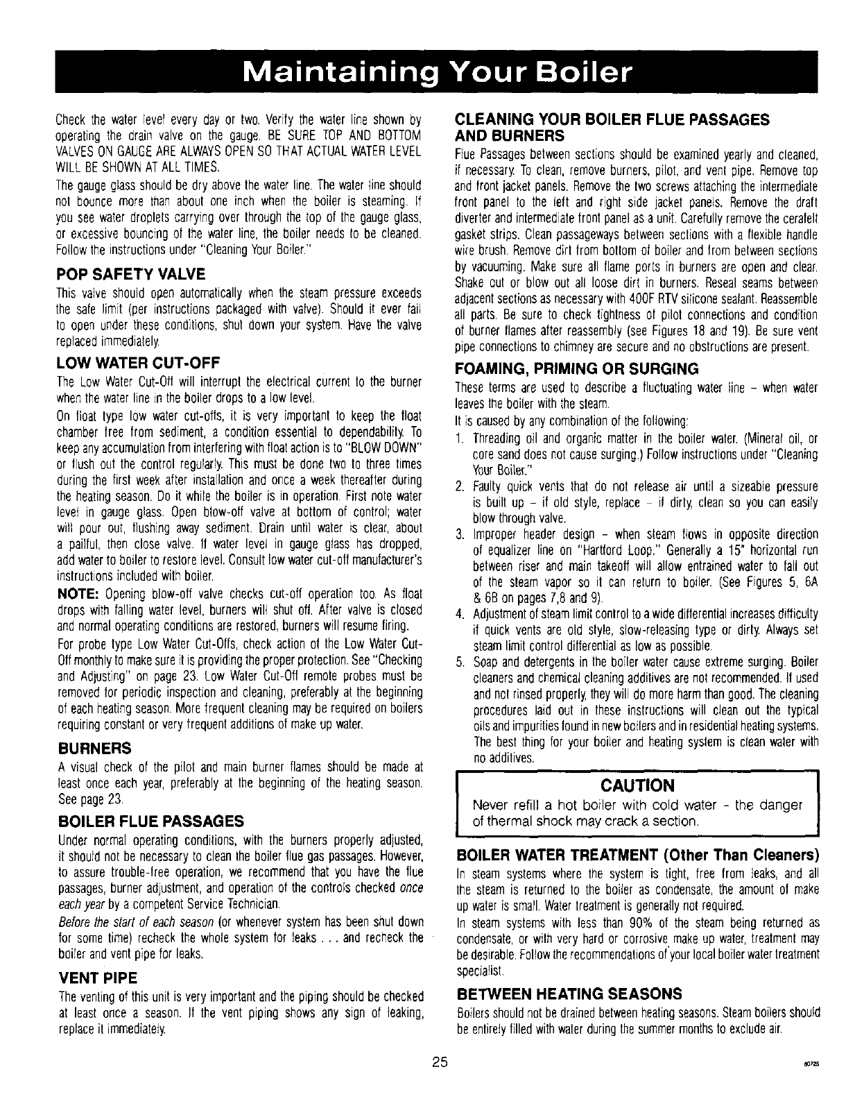
CLEANING YOUR BOILER FLUE PASSAGES
AND BURNERS
FluePassagesbetweensectionsshouldbe examinedyearlyandcleaned,
if necessaryTo clean,removeburners,pilot,andvenl pipe,Removetop
andfrontjacketpanels.Removethetwo screwsattachingthe intermediate
front pand 1o lhe left and righl side jacket panels.Removethe draft
diverlerandintermediatefrontpanelasa unit.Carefullyremovethecerafeg
gasketstrips. Cleanpassagewaysbetweensectionswitha flexiblehandle
wire brush.Removedirt from botlomof boilerandfrom betweenseclions
by vacuuming,Makesure all flameports in burnersare openand clear.
Shakeout or blow out all loose dirt in burners.Resealseamsbetween
adjacentsectionsas necessarywith400F RTVsiliconesealant.Reassemble
all parts.Be sure to checktightnessof pilot connectionsand condftion
of burnerflamesafterreassemNy(seeFigures18 and19). Besure vent
pipeconnectionsto chimneyaresecureandnoobslructionsarepresent.
FOAMING, PRIMING OR SURGING
Theseterms areused to describea fluctuatingwaterline - whenwater
leavestheboilerwiththesteam.
It is causedby anycombinationof the following:
1. Threadingoil andorganicmatterin the boiler water,(Mineraloil, or
coresanddoesnot causesurging.)Followinstructionsunder"Cleaning
YourBoiler."
2. Faultyquick ventsthat do not releaseair unlil a sizeablepressure
is built up - if old style, reptace it dirty cleanso you can easily
blowthroughvalve.
3. Improperheaderdesign - when steam flowsin oppositedirection
of equalizerlineon "HartfordLoop." Generallya 15" horizontalrun
betweenriser andmain takeoffwill allow entrainedwaterto fall out
of the steam vapor so it can return to boiler. (SeeFigures5, 6A
&6B onpages7,8 and9).
4. Adjustmentof steamlimitcontroltoawidedifferentialincreasesdifficulty
if quick ventsare old style, slow-releasingtype or dirty Alwaysset
steamlimitcontroldifferentialas low aspossible.
5. Soapanddetergentsin the boilerwatercauseextremesurging.Boiler
cleanersandchemicalcleaningadditivesarenotrecommended.If used
andnot rinsedproperlytheywill demoreharmthangood.Thecleaning
procedureslaid out in these instructionswill clean out the typical
oilsandimpuritiesfoundinnewboilersandinresidentialheatingsystems.
Thebestthing for yourboilerand heatingsystemis cleanwaterwith
noadditives.
CAUTION ]
Never refill a hot boiler with cold water - the danger
of thermal shock may crack a section.
BOILER WATER TREATMENT (Other Than Cleaners)
In steamsystemswhere the systemis tight, free from leaks,and all
the steamis returnedto the boiler as condensate,the amountof make
upwateris small,Watertreatmentis generallynotrequired.
In steamsystemswith less than 90% of the steam beingreturnedas
condensate,or wilh veryhardor corrosivemakeup water,treatmentmay
bedesirable.Followtherecommendationsof'yourlocalboilerwatertreatment
speciafisl.
BETWEEN HEATING SEASONS
Boilersshouldnotbedrainedbetweenheatingseasons.Steamboilersshould
beentiretyfilledwithwaterduringthesummermonthsto excludeair.
5 _1_
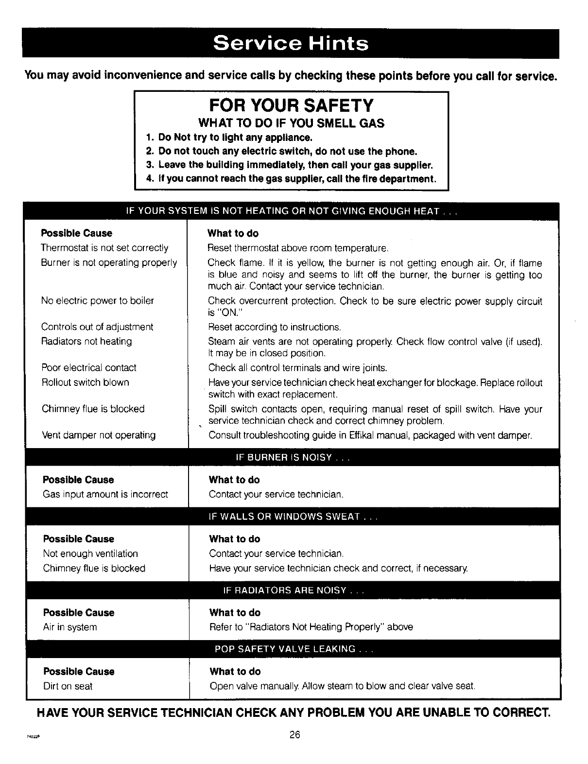
You may avoid inconvenience and service calls by checking these points before you call for service.
FOR YOUR SAFETY
WHAT TO DO IF YOU SMELL GAS
1. Do Not try to light any appliance.
2. Do not touch any electric switch, do not use the phone.
3. Leave the building immediately, then call your gas supplier.
4. If you cannot reach the gas supplier, call the fire department.
Possible Cause
Thermostat is not set correctly
Burner is not operating properly
No electric power to boiler
Controls out of adjustment
Radiators not heating
Poor electrical contact
Rollout switch blown
Chimney flue is blocked
Vent damper not operating
Possible Cause
Gas input amount is incorrect
Possible Cause
Not enough ventilation
Chimney flue is blocked
Possible Cause
Air in system
Possible Cause
Dirt on seat
What to do
Reset thermostat above room temperature.
Check flame. If it is yellow, the burner is not getting enough air. Or, if flame
is blue and noisy and seems to lift off the burner, the burner is getting too
much air. Contact your service technician.
Check overcurrent protection. Check to be sure electric power supply circuit
is "ON."
Reset according to instructions.
Steam air vents are not operating properly. Check flow control valve (if used).
It may be in closed position.
Check all control terminals and wire joints.
Have your service technician check heat exchanger for blockage. Replace rollout
switch with exact replacement.
Spill switch contacts open, requiring manual reset of spill switch. Have your
service technician check and correct chimney problem.
Consult troubleshooting guide in Effikal manual, packaged with vent damper,
What to do
Contact your service technician.
What to do
Contact your service technician.
Have your service technician check and correct, if necessary
What to do
Refer to "Radiators Not Heating Properly" above
HAVE YOUR SERVICE TECHNICIAN CHECK ANY PROBLEM YOU ARE UNABLE TO CORRECT.
..... 26
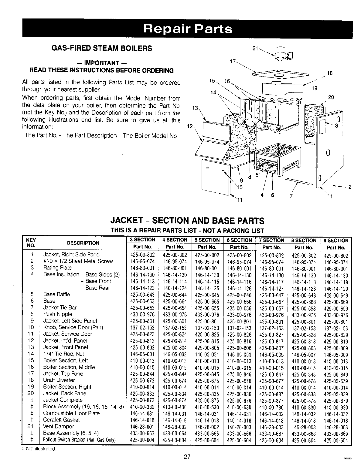
GAS-FIRED STEAM BOILERS
-- IMPORTANT --
READ THESE INSTRUCTIONS BEFORE ORDERING
All parts listed in the following Parts List may be ordered
through your nearest supplier.
When ordering parts, first obtain the Model Number from
the data plate on your boiler, then determine the Part No.
(not the Key No.} and the Description of each part from the
following illustrations and list. Be sure to give us all this
information:
The Part No, - The Part Description - The Boiler Model No.
15\ 16.
10
18
. _ 19 20
4 6 7
0
/
"1
JACKET -SECTION AND BASE PARTS
THIS IS A REPAIR PARTS LIST -NOT A PACKING LIST
KEY
NO.
1
2
3
4
5
6
7
8
DESCRIPTION
Jacket, Right Side Panel
:#10 x 1/2 Sheet Metal Screw
Rating Plate
Base Insulation - Base Sides (2)
3 SECTION
Part No.
425-00-802
146-95-074
146-80-001
146-14-130
4 SECTION
Part No.
425-00-802
146-95-074
I46-80-001
146-14-130
5 SECTION
Part No.
425-00-802
146-95-074
146-80-001
146-14-130
6 SECTION
Part No.
425-00-602
146-95-074
146-80-001
146-14-130
7 SECTION
Part No,
425-00-802
146-95-074
146-80-001
146-!4-130
8 SECTION
Part No,
425-00-802
146-95-074
146-80-001
146-!4-130
-Base Front
Base Rear
Base Baffle
Base
JacketTie Bar
Push Nipple
Jacket, Left Side Panel
Knob, Service Door (Pair}
146-14-113
146-14-123
425-00-643
425-00-663
425-00-653
433-00-976
425-00-801
137-02-153
146-14-114
146-14-124
425-00-644
425-00-664
425-00-654
433-00-976
425-00-801
137-02-153
146-!4-115
146-14-125
425-00-645
425-00-665
425-00 655
433-00-976
425-00-801
137-02-153
146-14-116
146-14-126
425-00-646
425-00-666
425-00-656
433-00-976
425-00-801
137-02-153
146-14-1!7
146-14-127
425-00-647
425-00-667
425-00-657
433-00-976
425-00-801
t37-02-153
146-14-118
146-14-128
425-00-648
425-00-668
425-00-658
433-00-976
425-00-801
137-02-153
9
10
! ! Jacket, Service Door
12 Jacket, Int'd Panel
13 Jacket, Front Panel
14 1/4" Tie Rod, Nut
15 Boiler Section, Left
16 Boiler Section, Middle
17 Jacket, Top Panel
18 Draft Diverter
19 Boiler Section, Right
20 ! Jacket, Back Panel
:I: Jacket Complete
:l: Block Assembly (19, 16, 15, 14, 8)
qt: Combustible Floor Plate
:i: Cerafelt Gasket
21 Vent Damper
:i: Base Assembly (6, 5, 4}
$ RolloutSwitchBracket(Nat,GasOnly)
42500-823
425-00-813
425-00-803
146-05-001
410-00-013
410-00-015
425-00-844
425-00-673
410-00-014
425-00-833
425-00-873
410-00-330
146-14-031
146-14-018
146-28-001
433-00-663
425-00-604
425-00-824
425-00-814
425-00-804
146-05-002
410-00-013
410-00-015
425-00-844
425-00-674
410-00-014
425-00-834
425-00-874
410-00-430
146-14-031
146-14-018
146-28-002
433-00-664
425-00-604
425-00-825
425-00-815
425-00-805
146-05-051
410-00-013
410-00-015
425-00-845
425-00-675
410-00-014
425-00-835
425-00-875
410-00-530
146-14;031
146-14-018
146-28-002
433-00-665
425+00-604
425-00-826
425-00-816
425-00-806
146-05-053
410-00-013
410-00-015
425-00-846
425-00-676
410-00-014
425-00-836
425-00-876
410-00-630
146-14-031
146-14-018
146-28-003
433-00-666
425-00-604
425-00-827
425-00-817
425-00-807
146-05-005
410-00-013
410-00-015
425-00-847
425-00-677
410-00-014
425-00-837
425-00-877
410-00-730
146-14-032
146-14-018
146-28-003
433-00-667
425-00-604
425-00-828
425-00-818
425-00 808
146-05-007
410-00-013
410-00-015
425-00-848
425-00-678
410-00-014
425-00-838
425-00-878
410-00-830
146-14-032
146-14-018
146-28-003
433-00-668
425-00-604
9 SECTION
Part No.
425-00-802
146-95-074
146 80-001
146-14-130
146-14-119
146-14-129
425-00-649
425-00-669
425-00-659
433-00-976
425-00-801
137-02-153
425-00-829
426-00-819
425-00-809
146-05-009
410-00-013
410-00-015
425-00-849
425-00-679
410-00-014
425-00-839
425-00-879
410-00-930
146-14-032
146-14-018
146-28-003
433-00-669
425-0O-604
:l-Not illustrated.
27 ....
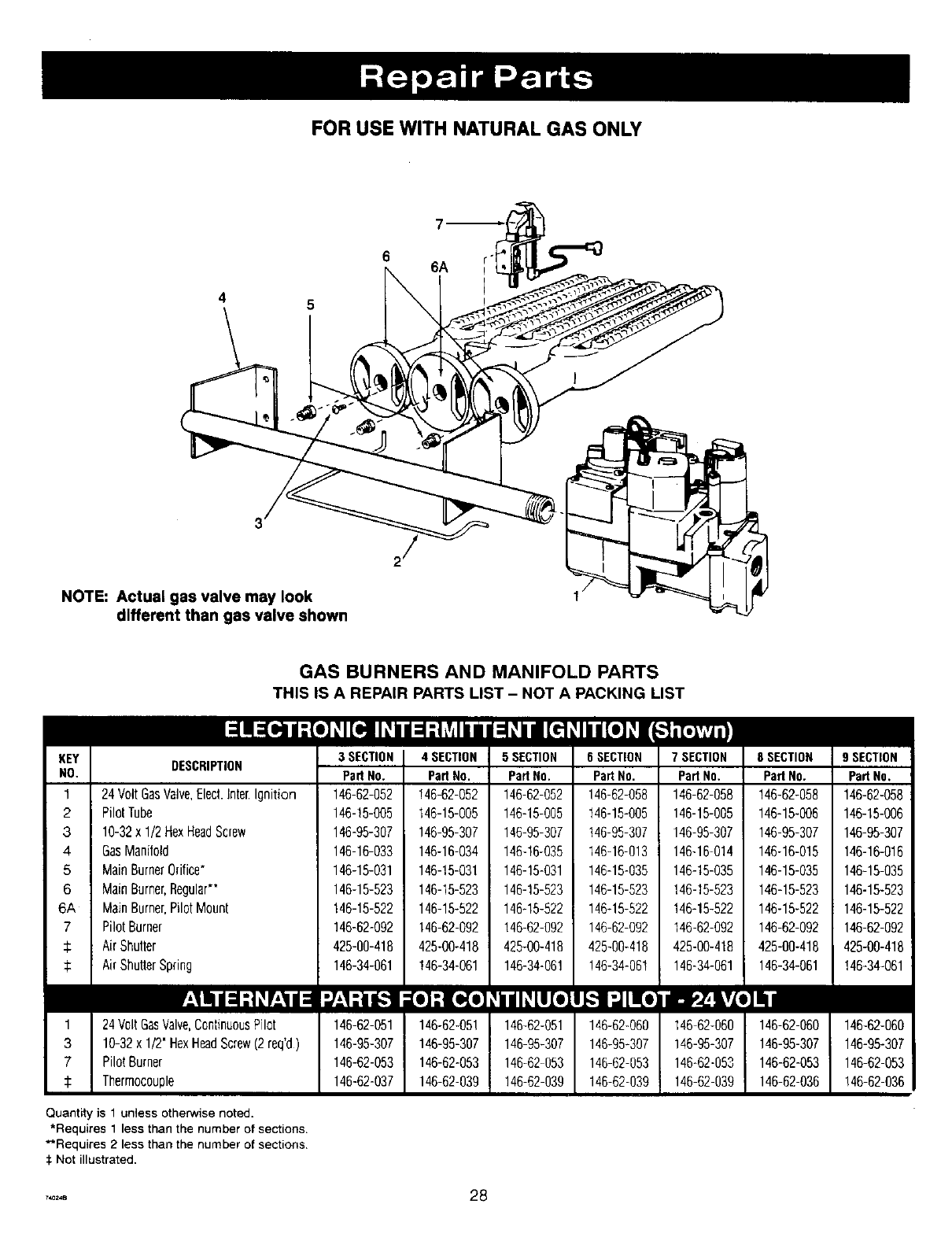
FOR USE WITH NATURAL GAS ONLY
6
4 5
NOTE: Actual gas valve may look
different than gas valve shown
II
KEY
NO.
1
2
3
4
5
6
6A
7
1
3
7
GAS BURNERS AND MANIFOLD PARTS
THIS iS A REPAIR PARTS LIST - NOT A PACKING LIST
DESCRIPTION
24Volt GasValve,Elect.Inter.Ignition
PilotTube
10-32x 1/2HexHeadScrew
GasManifold
MainBurnerOrifice"
MainBurner,Regular*"
MainBurner,PilotMount
Pilot Burner
AirShutter
AirShutterSpring
24Volt GasValve,ContinuousPilot
10-32x 1/2" HexHeadScrew(2 req'd)
Pilot Burner
Thermocouple
3 SECTION
Pad No.
146-62-052
146-15-005
146-95-307
146-16-033
146-15-031
146-15-523
146-15-522
146-62-092
425-00-418
146-34-061
146-62-051
146-95-307
146-62-053
146-62-037
4 SECTION
PadNo.
!46-62-052
146-15-005
146-95-307
146-16-034
146-15-031
146-15-523
146-15-522
146-62-092
425-00-418
!46-34-061
146-62-051
146-95-307
146-62-053
146-62-039
5 SECTION
PadNo.
146-62-052
146-15-005
146-95-307
146-16-035
146-15-031
146-15-523
146-15-522
146-62-092
425-00-418
146-34-061
146-62-051
146 95-307
146-62-053
146-62-039
6 SECTION
Pa_No.
146-62-058
146-15-005
146-95-307
146-16-013
146-15-035
146-15-523
146-15-522
146-62-092
425-00-418
!46-34-061
146-62-060
146-95-307
146-62-053
146-62-039
7 SECTION
Pad No.
146-62-058
146-15-005
146-95-307
146-16-014
146-15-035
146-15-523
146-15-522
146-62-092
425-00-418
146-34-061
146-62-060
146-95-307
146-62-053
146-62-039
8 SECTION
Pad No.
!46-62-058
146-15-006
146-95-307
146-16-015
146-15-035
146-15-523
146-15-522
146-62-092
425-00-418
146-34-061
146-62-060
146-95-307
146-62-053
146-62-036
Quantity is 1 unless otherwise noted.
*Requites 1 less then the number of sections.
**Requires 2 less than the number of sections.
:i:Not illustrated.
9 SECTION
PadNo.
146-62-058
146-15-006
146-95-307
146-16-016
146-15-035
146-15-523
146-15-522
146-62-092
425-00-418
146-62-060
146-95-307
146-62-053
!46-62-036
..... 28
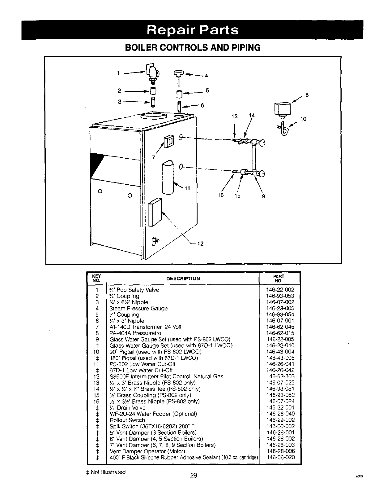
BOILER CONTROLS AND PIPING
12
KEY
NO. DESCRIPTION
1
2
3
4
5
6
7
8
9
10
11
12
13
14
15
16
I
¾' Pop Safety Valve
%"Coupling
Y," x 6W' Nipple
Steam Pressure Gauge
'/4' Coupling
YY x 3" Nipple
AT-140D Transformer, 24 Volt
PA-404A Pressuretrol
Glass Water Gauge Set (used with PS-802 LWCO)
Glass Water Gauge Set (used with 67D-1 LWCO)
90" Pigtail (used with PS-802 LWCO)
180" Pigtail (used with 67D-1 LWCO)
PS-802 Low Water Cut-Off
67D-1 Low Water Cut-Off
! $8600F Intermittent Pilot Control, Natural Gas
W' x 3" Brass Nipple (PS-802 only)
'½"x 'A" x ¼" Brass Tee (PS-802 only)
IY2"Brass Coupling (PS-802 only)
,W' x 3W' Brass Nipple (PS-802 only)
¾" Drain Valve
WF-2U-24 Water Feeder (Optional)
Rollout Switch
Spill Switch (36TX16-6282) 280" F
5" Vent Damper (3 Section Boilers)
6" Vent Damper (4, 5 Section Boilers)
7" Vent Damper (6, 7, 8, 9 Section Boilers)
Vent Damper Operator (Motor)
400 °F Black Silicone Rubber Adhesive Sealant (10.3oz.cadridge)
PART
NO.
146-22-002
146-93-053
146-07-002
146-23-005
146-93-054
146-07-301
146-62-045
146-62-015
146-22-005
146-22-010
146-43-004
146-43-005
146-26-041
146-26-042
146-62-303
146-07-025
146-93-051
146-93-052
146-07-024
146-22-001
146-26-040
146-29-002
146-60-002
146-28-301
146-28-002
146-28-003
146-28-006
146-08-020
Not Illustrated 29 ,_,,,
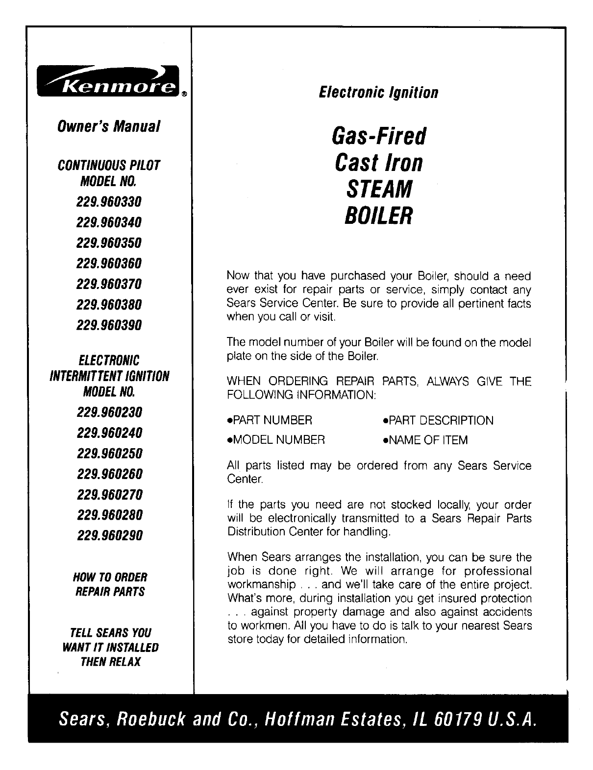
Owner'sManual
CONTINUOUSPILOT
MODELNO.
229.960330
229.960340
229.960350
229.960360
229.960370
229.960380
229.960390
ELECTRONIC
INTERMITTENTIGNITION
MODELNO.
229.960230
229.960240
229.960250
229.960260
229.960270
229.960280
229.960290
HOW TO ORDER
REPAIRPARTS
TELLSEARS YOU
WANTIT INSTALLED
THEN RELAX
®ElectronicIgnition
Gas-Fired
CastIron
STEAM
BOILER
Now that you have purchased your Boiler, should a need
ever exist for repair parts or service, simply contact any
Sears Service Center. Be sure to provide all pertinent facts
when you call or visit.
The model number of your Boiler will be found on the model
plate on the side of the Boiler.
WHEN ORDERING REPAIR PARTS, ALWAYS GIVE THE
FOLLOWING INFORMATION:
• PART NUMBER
eMODEL NUMBER
• PART DESCRIPTION
eNAME OF ITEM
All parts listed may be ordered from any Sears Service
Center.
If the parts you need are not stocked locally, your order
will be electronically transmitted to a Sears Repair Parts
Distribution Center for handling.
When Sears arranges the installation, you can be sure the
job is done right. We will arrange for professional
workmanship.., and we'll take care of the entire project•
What's more, during installation you get insured protection
• . . against property damage and also against accidents
to workmen. All you have to do is talk to your nearest Sears
store today for detailed information.
