Kenmore 23351844591 User Manual RANGE HOOD Manuals And Guides L0504529
KENMORE Range Hood Manual L0504529 KENMORE Range Hood Owner's Manual, KENMORE Range Hood installation guides
User Manual: Kenmore 23351844591 23351844591 KENMORE RANGE HOOD - Manuals and Guides View the owners manual for your KENMORE RANGE HOOD #23351844591. Home:Kitchen Appliance Parts:Kenmore Parts:Kenmore RANGE HOOD Manual
Open the PDF directly: View PDF ![]() .
.
Page Count: 24

ood
Use & Care /installation Manual
cocina
Manual de uso y cuidado /instalaci6n
Models
Modelos
233.51840591
233.51841591
233.51844591
233.51848591
(30" wide -Stainless)
(30" wide -White)
(30" wide -Bisque)
(30" wide -Almond)
0
u
¢0
O
99043202D Sears, Roebuck and Co,, Hoffman Estates, UL60179 U,S,A, www,sears,com
SECTION ..................................................................... PAGE
Warranty .............................................................................. 2
Safety Instructions ............................................................... 2
Operation ............................................................................. 3
Cleaning .............................................................................. 3
Parts Included With Hood ................................................... 4
Parts Not Included With Hood ............................................ 4
Tools Needed ...................................................................... 4
Equivalent Duct Length Chart ............................................ 5
Prepare The Hood Location ............................................... 6
Prepare The Hood .......................................................... 7, 8
Connect The Wiring ............................................................ 9
Install The Hood ................................................................ 10
Service Parts ..................................................................... 11
If within 1 year from the date of installation, any part of this
range hood fails to function properly due to a defect in mate-
rial or workmanship, Sears will repair the part or furnish and
install a new part, free of charge.
FULL 30_DAY WARRANTY ON FIN_SH ON PAINTED OR
BRIGHT METAL PARTS
If within 30 days from the date of installation, the finish on any
painted or bright metal parts of this range hood is defective in
material or workmanship, Sears will furnish and install a new
_art, free of charge.
WARRANTY SERVICE iS AVAILABLE BY CONTACTING
THE NEAREST SEARS SEVICE CENTER/DEPARTMENT
iN THE UNITED STATES.
This warranty applies onty while this product is in use in the
United States. This warranty gives you specific legal rights
and you may have other rights which vary from state to state.
Sears, Roebuck and Co., Dept 817WA, Hoffman Estates,
IL 60179
WARNING ,_, A
A iNTENDEDFOR DOMESTICCOOKINGONLY.
TO REDUCE THE RiSK OF FIRE, ELECTRIC SHOCK, OR
iNJURY TO PERSONS, OBSERVE THE FOLLOWING:
1. Use this unit only in the manner intended by the manufac-
turer. If you have questions, contact the manufacturer at
the address listed in the warranty.
2. Before servicing or cleaning unit, switch power off at service
panel and lock the service disconnecting means to prevent
power from being switched on accidentally. When the
service disconnecting means cannot be locked, securely
fasten a prominent warning device, such as a tag, to the
service panel.
3. Installation work and electrical wiring must be done by a
qualified person(s)in accordance with all applicable codes
and standards, including fire-rated codes and standards.
4. Sufficient air is needed for proper combustion and
exhausting of gases through the flue (chimney) of fuel
burning equipment to prevent backdrafting. Follow the
heating equipment manufacturer's guideline and safety
standards such as those published by the National Fire
Protection Association (NFPA), and the American Society
for Heating, Refrigeration and Air Conditioning Engineers
(ASHRAE), and the local code authorities.
5. When cutting or drilling into wal! or ceiling, do not damage
electrical wiring and other hidden utilities.
6. To reduce the risk of fire or electric shock, do not use this
range hood with an additional speed control device.
7. Ducted fans must always be vented to the outdoors.
8. To reduce the risk of fire, use only metal ductwork.
9. Use with approved cord-connection kit only.
10.This unit must be grounded.
TO REDUCE THE RISK OF A RANGE TOP GREASE FIRE:
1. Never leave surface units unattended at high settings.
Believers cause smoking and greasy spillovers that may
ignite. Heat oils slowly on low or medium settings.
2. Always turn hood ON when cooking at high heat or when
cooking flaming foods.
3. Clean ventilating fans frequently. Grease should not be
allowed to accumulate on fan or filter.
4. Use proper pan size. Always use cookware appropriate for
the size of the surface element. 2
WARNING ,_, ,_
TO REDUCE THE RiSK OF INJURY TO PERSONS IN THE
EVENT OF A RANGE TOP GREASE FIRE, OBSERVE THE
FOLLOWING:*
1. SMOTHER FLAMES with a close-fitting lid, cookie sheet,
or metal tray, then turn off the burner. BE CAREFUL TO
PREVENT BURNS. If the flames do not go out immediately,
EVACUATE AND CALL THE FIRE DEPARTMENT.
2. NEVER PICK UPA FLAMING PAN - You may be burned.
3. DO NOT USE WATER, including wet dishcloths or towels
- a violent steam explosion will result.
4. Use an extinguisher ONLY if:
A. You know you have a Class ABC extinguisher and you
already know how to operate it.
B. The fire is small and contained in the area where it
started.
C. The fire department is being called.
D. You can fight the fire with your back to an exit.
* Based on "Kitchen Firesafety Tips" published by NFPA.
CAUTION ,_
1. For general ventilating use only'. Do not use to exhaust
hazardous or explosive materials and vapors.
2. To avoid motor bearing damage and noisy and/or
unbalanced impellers, keep drywall spray, construction
dust, etc. off power unit.
3. For best capture of cooking impurities, your range hood
should be mounted so that the top of the hood is 24-30"
above the cooking surface.
4. Use only with range hood cord-connection kits that have
been investigated and found acceptable for use with this
model range hood.
5. Please read specification label on product for further
information and requirements.
tf hood is to be instatmed Non-Ducted:
o Purchase a nonoducted fiBter from your local distributor or
retailer and install it beneath the aluminum mesh filter.
Fan
The fan switch is a solid-state speed control. Rotate the switch
clockwise - to turn the fan ON to HIGH speed. Continue rotat-
ing the switch clockwise - to reduce the fan speed.
Light
The light switch has 3 positions. The light is OFF when the
switch is rotated fully counterclockwise. Rotate the switch
clockwise to second position - for normal lighting. Rotate the
switch clockwise to the third position - for a night light.
_ WARNING: To reduce the risk of electric shock,
disconnect from power supply before cJean-
rag.
ABuminum mesh filter
Clean frequently using hot water and a mild detergent or in
your dishwasher. The aluminum mesh filter should be washed
approximately every month depending on the amount of us-
age. Wash more often if your cooking style generates greater
grease - like frying foods or wok cooking.
Nonoducted filter (CmeanCooking hoods onmy)
(available separately -see page 4)
Clean filter surfaces frequently with a damp cloth and a mild
detergent. DO NOT immerse filter in water or put in dish-
washer. The special "Clean Sense" feature indicates when the
filter is to be replaced. The blue and yel!ow strips will blend to
green when it is time to change the filter. The "Clean Sense"
feature works best when facing toward the cooking surface.
Painted hood surfaces
Wiping regularly with mild soap/detergent and warm water
should protect painted hood surfaces. Be cautious about us-
ing "New and Improved" cleaning agents. Your hood is installed
over hot cooking equipment. Most chemicaIs found in clean-
ing agents react with heat to loosen paint.
Stainless steem hood surfaces
Stainless steel hoods should be washed regularly with a clean
cloth, warm water and mild soap or dish detergent. Clean in
the direction of the polish lines. Rinse well with clear water
and wipe dry immediately. You may wish to apply light oil used
for furniture polishing to emphasize it's bright finish.
Fan assembBy
Fan bIade can be cteaned with a damp ctoth and mild deter-
gent. Use care when cteaning fan blade - it must not become
bent or misaligned. DO NOTALLOW WATER TO ENTER MO-
TOR. Make sure all surfaces are completely dry before re-
installing filters and restoring power.
Motor is permanently lubricated. Do not oil or disassemble
motor.
O_
2
3

Aluminum Grease F{mter
Light Bumb
(75 W Maximum)
(1 per hood)
Purchase IocaIly.
Parts Bag
(4 hood mounting screws inside)
OPTmONAL PARTS (purchase separateJy)
NonoDucted Kit
(Clean Cooking Filter)
(1 per hood)
Sears Part No. 50183
SpBashpBate
Sears Part Nos.
58120 30" Black/Bisque
58128 30" White/AImond
58129 30" Stainless
Cord Kit
(Allows hood to be plugged into a
standard 120 VAC wall outlet)
Sears Part No. 233.22HCK44D
Ducting Accessories
(See "EquivaIent Duct Length Chart" on page 5 for Ducting
Accessory Model Nos.)
1
"Parts Not _ncluded With Hood" avaimabJe by calling |
Sears at l oS00-4oMY-HOME ®J
Sacrewdriver
t & Phillips)
Saw 4
TaPe
asure
Duct
Tape
_N !/4"
utdriver
4_S wire
tripper
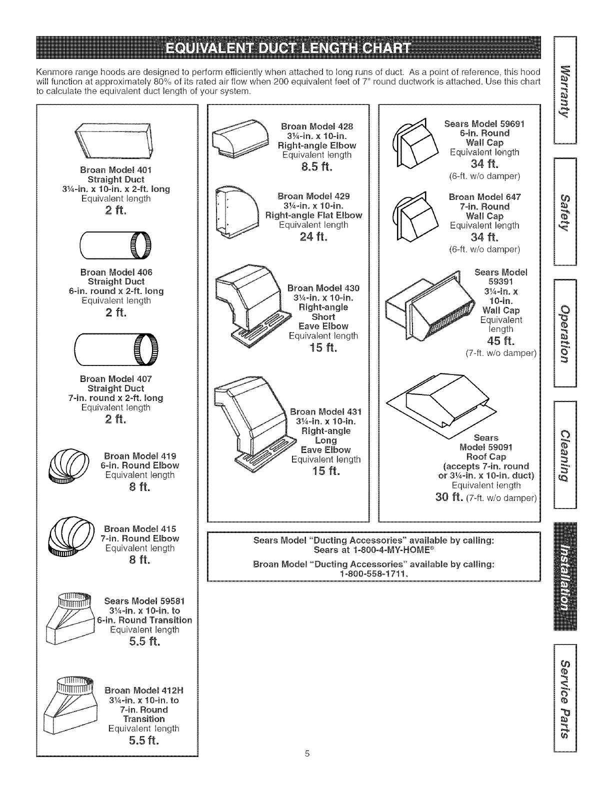
KenmorerangehoodsaredesignedtoperformefficientlywhenattachedtoIongrunsofduct.Asapointofreference,thishood
wiIIfunctionatapproximately80%ofitsratedairftowwhen200equivalentfeetof7"roundductworkisattached.Usethischart
tocalculatetheequivalent duct length of your system.
Broan Modem 401
Straight Duct
3¼=in, × 10-in, × 2=ft, mong
Equivalent length
2ft.
( O
Broan Modem 406
Straight Duct
64n. round × 2-ft, long
Equivalent length
2 ft.
( O
Broan Modem 407
Straight Duct
7-in. round × 2-ft. long
EquivaIent Iength
2 ft.
Broan Modem419
64n, Round Elbow
Equivalent length
8 ft.
Broan Modem415
7-in, Round Elbow
Equivalent length
8 ft.
Sears Model 59581
3¼-in, ×10-in. to
6=in. Round Transition
Equivalent length
5.5 ft.
Broan Model 412H
3¼=in, × lO-in, to
74no Round
Transition
Equivalent Iength
5.5 ft.
Broan Model 428
3¼-in° × 10=in.
Right=angBe Embow
Equivalent Iength
8.5 ft.
Broan _'1odel 429
3¼-in. × 10-ino
Right-angle Fiat Elbow
Equivalent length
24 ft.
Broan Model 430
3¼-in. × 1O-ino
Right-angme
Short
Eave E{bow
quivalent length
15 ft.
Broan Model 431
3¼-in, x 10-in.
Right-angle
Long
Eave Elbow
quivalent length
15 ft.
(_ Sears Modem 59691
8=in° Round
Wall Cap
Equivalent length
34 ft.
(6-ft= w/o damper)
(_ Broan Modem 647
74n. Round
WaR Cap
Equivalent length
34 ft.
(6-ft= w/o damper)
Sears Model
59391
3¼=in. x
10-in,
WaR Cap
Equivalent
length
45 ft.
(7-ft= w/o damper)
Model 59091
Roof Cap
(accepts 74n. round
or 3¼-in. × lO-in, duct}
Equivalent Iength
30 ft. (7-fL W/Odamper)
Sears Modet "Ducting Accessories" avaimabmeby caring:
Sears at 1-800=4=[v]Y=HOME®
Broan Modet "Ducting Accessories" availabme by caring:
1_800=558=1711°
2
{b
re
t_
2
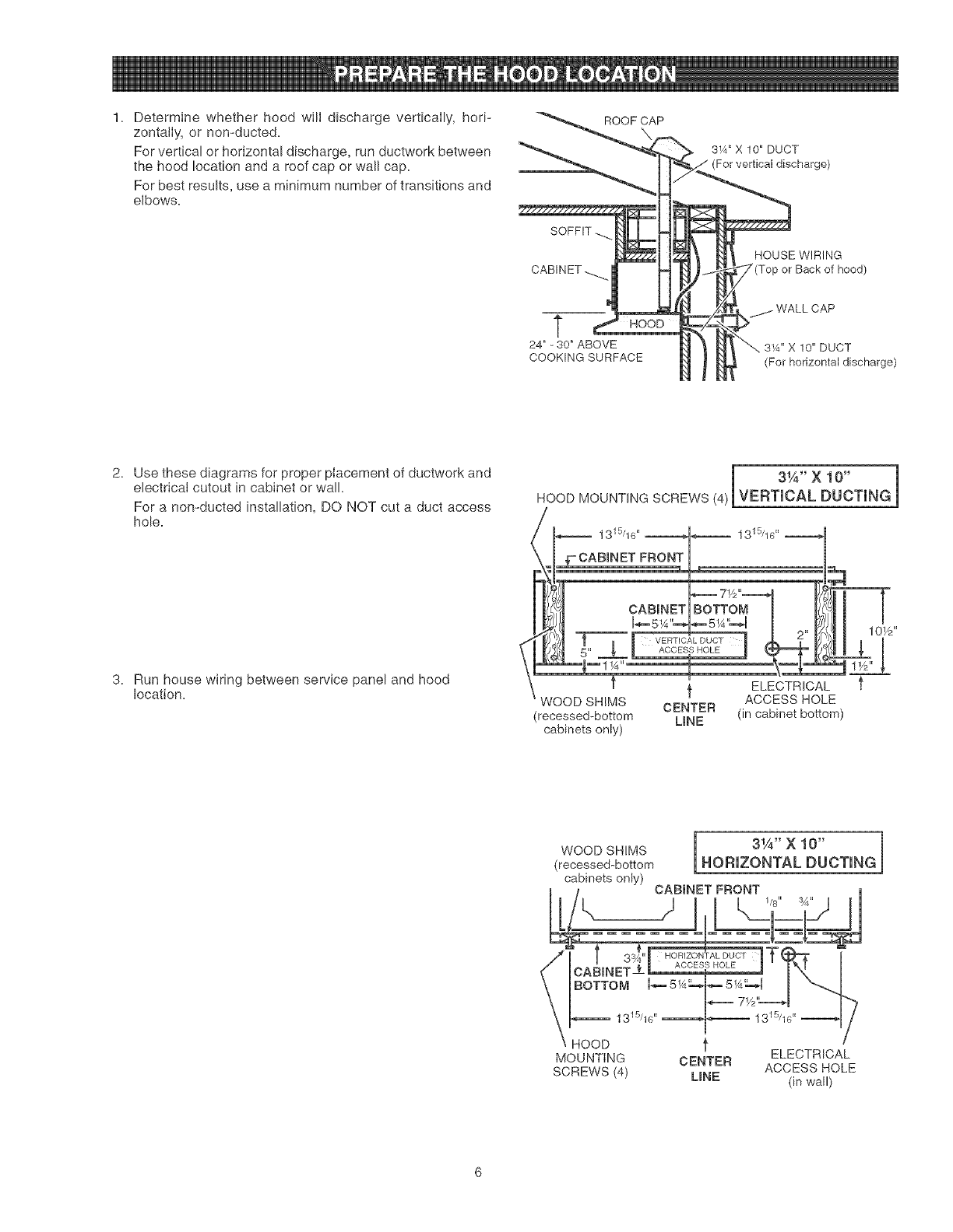
1. Determine whether hood will discharge vertically, hori-
zontally, or non-ducted.
For vertical or horizontal discharge, run ductwork between
the hood location and a roof cap or wall cap.
For best results, use a minimum number of transitions and
elbows.
ROOF CAP
SOFFIT
CABINET -._..
t
24" - 30" ABOVE
COOKINGSURFACE
3_A" X 10" DUCT
(For vertical discharge)
HOUSE WIRING
or Back of hood)
CAP
3_A'' X 10" DUCT
(For horizontal discharge)
2. Use these diagrams for proper placement of ductwork and
electrical cutout in cabinet or wall.
For a non-ducted installation, DO NOT cut a duct access
hole.
31A'X 10" 1
HOOD MOUNTING SCREWS (4)|VERT CAL DUCT NG
3. Run house wiring between service panel and hood
location.
±
CABmNET]BOTTOM ]
T=Tm vEm,o*Louo,7..k ,*"
5" _' m ACCESSHOLE m k_F -
t ELECTRICAL
ACCESS HOLE
WOOD SHIMS CENTER
(recessed-bottom LINE (in cabinet bottom)
cabinets only)
(recessed-bottom HORIZONTAL DUCTING
cabinets only) CABmNETFRONT
1/8" 3_"
CABINET-
BOTTOM
13 5/1G"
HOOD
MOUNTING
SCREWS (4)
1315/1G"
fELECTRICAL
CENTER ACCESS HOLE
LINE (in wall)
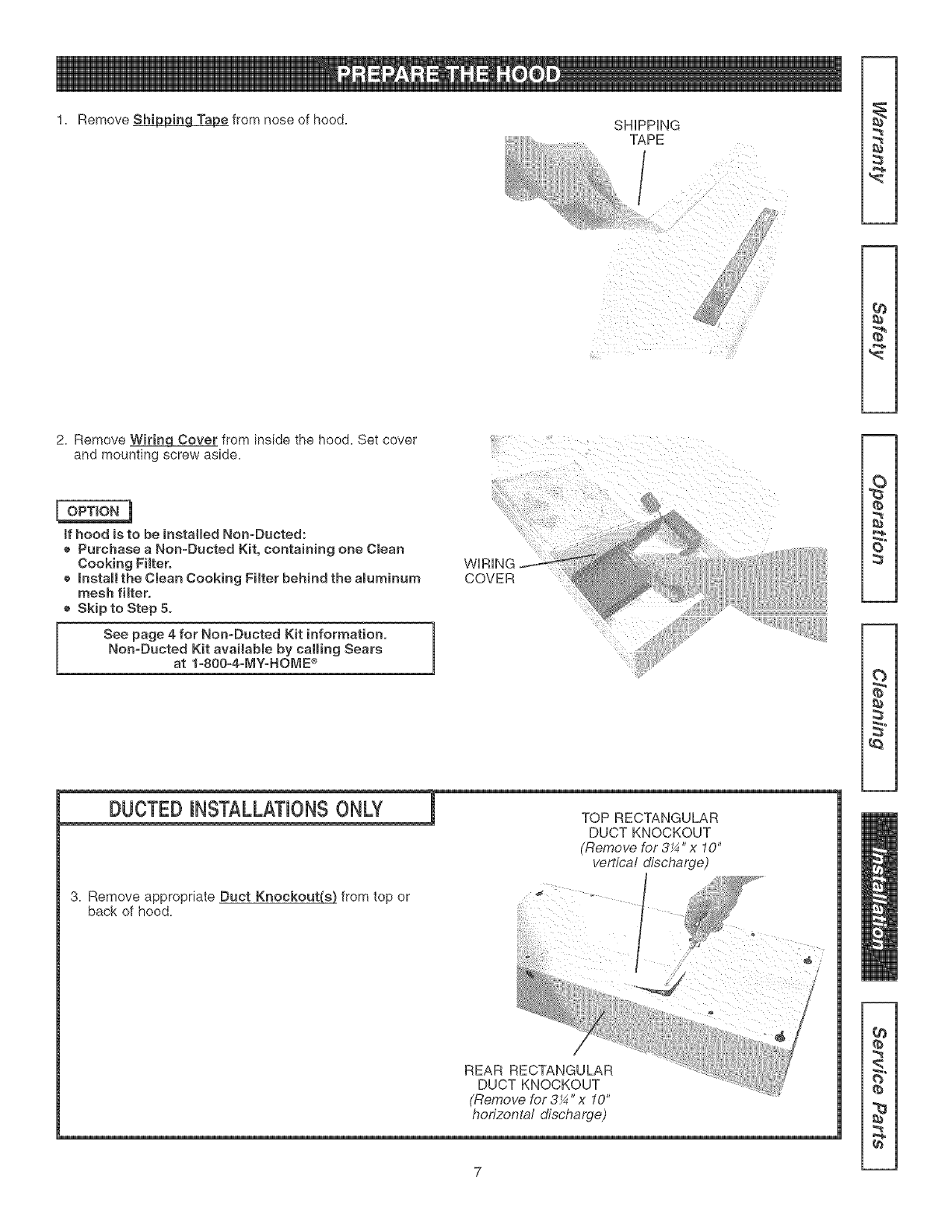
1. Remove_ fromnoseofhood. SHiPPiNG
................. TAPE
/
}/'
_{i!i!i!_!/
2. Remove WiringCover from inside the hood. Set cover
and mounting screw aside.
tf hood is to be installed Non-Ducted:
e Purchase a Non-Ducted Kit, containing one Clean
Cooking Filtero
e _nstaH the Clean Cooking Filter behind the aluminum
mesh filter.
e Skip to Step 5°
See page 4 for Non-Ducted Kit information,
Non-Ducted Kit availabme by calling Sears
at 1-800=4=MY-HOME _
COVER
(b
S"
3. Remove appropriate Duct Knockout_ from top or
back of hood.
TOP RECTANGULAR
DUCT KNOCKOUT
(Remove for 3X "x 10"
vertical discharge)
REAR RECTANGULAR
DUCT KNOCKOUT
(Remove for 3¼" x 10"
horizontal discharge)
_a
q_
7
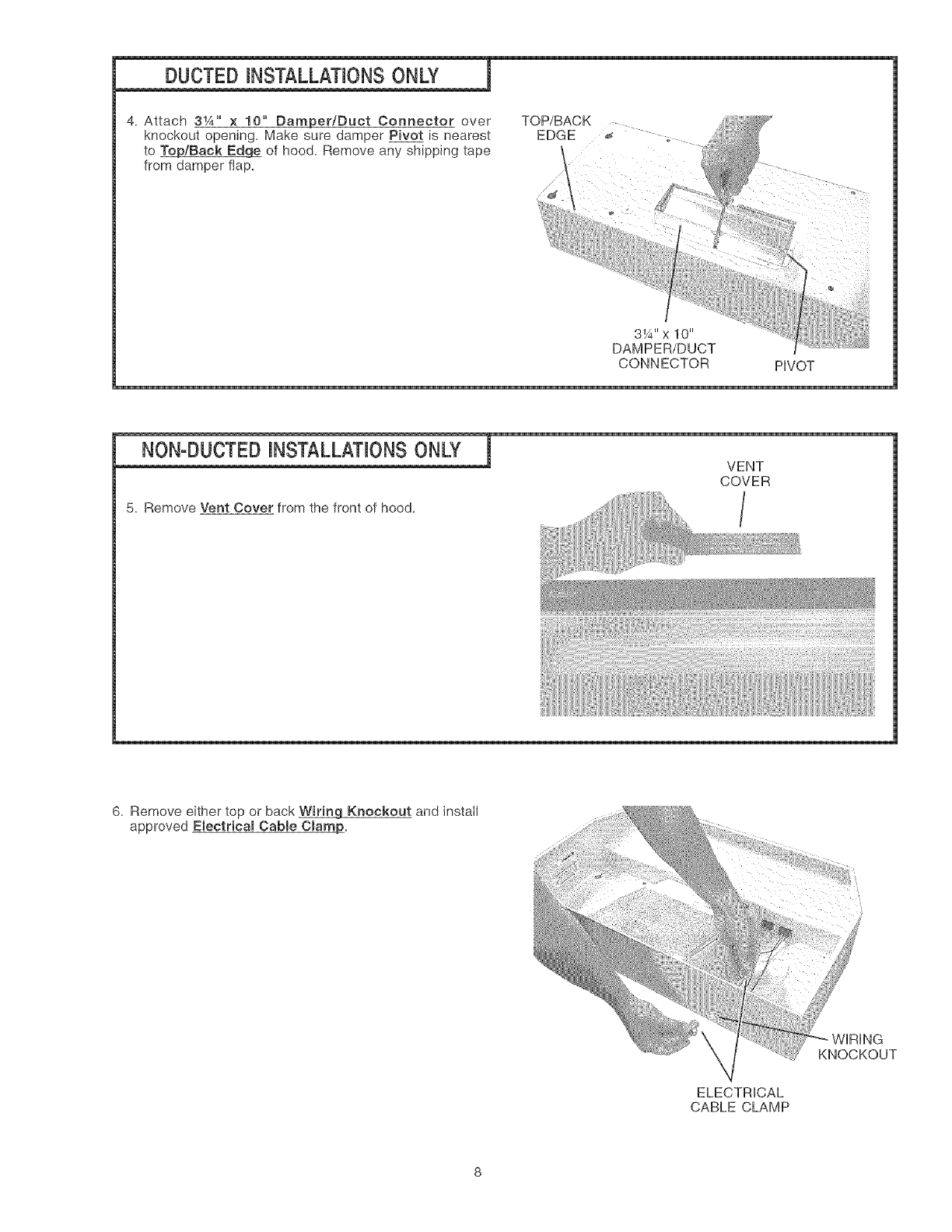
DUCTED HNSTALLATHONSONLY !
4. Attach 31A'' × 10" Damper/Duct Connector over
knockout opening, Make sure damper Pivot is nearest
to _/Back Edg£ of hood, Remove any shipping tape
from damper flap,
3¼"x 10"
DAMPER/DUCT
CONNECTOR PIVOT
5, Remove Vent Cover from the front of hood,
VENT
COVER
/
6. Remove either top or back Wiring Knockout and instaII
approved Electricam Cabme Cmamj_.
ELECTRICAL
CABLE CLAMP
WiRiNG
KNOCKOUT
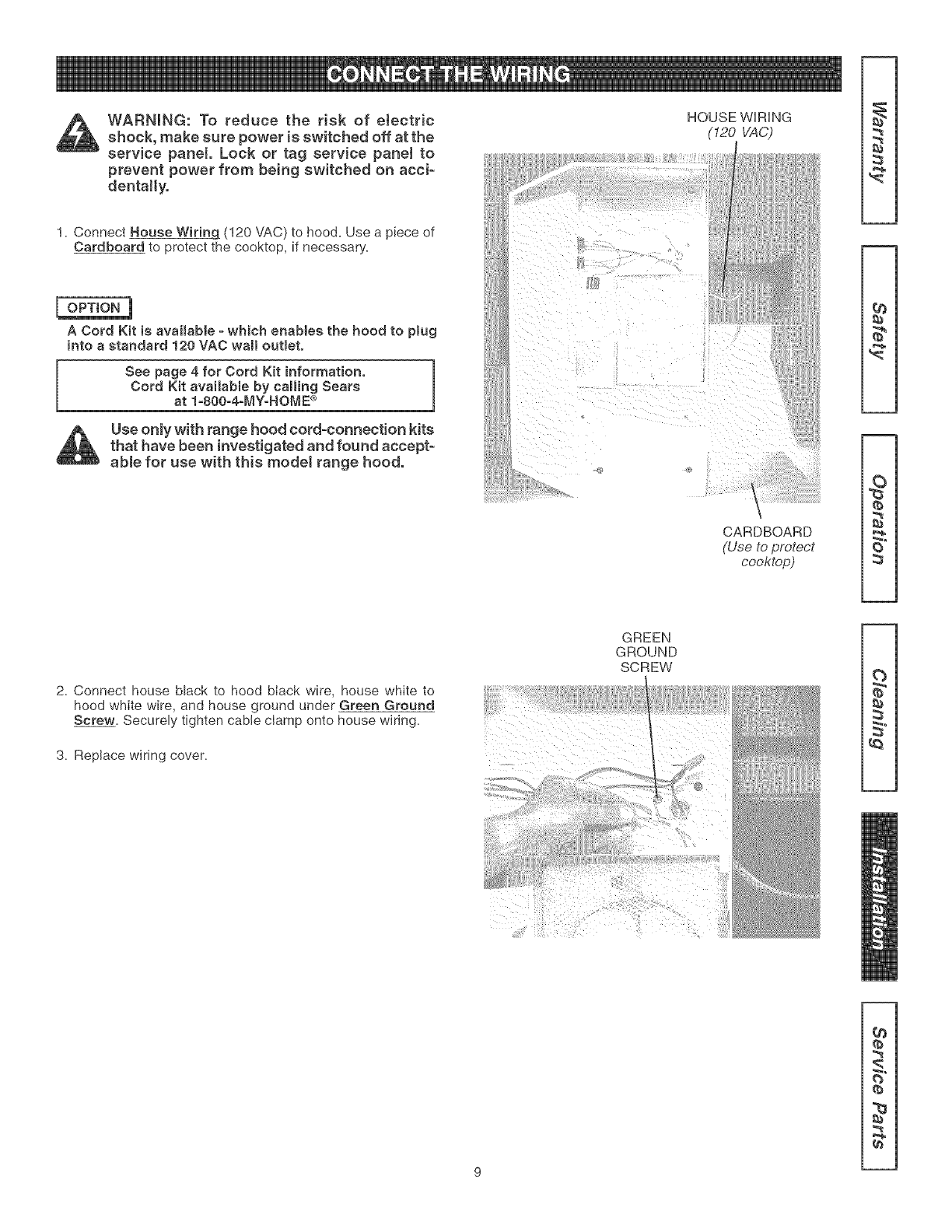
WARNING: To reduce the risk of eJectric
shock, make sure power is switched off at the
service panel. Lock or tag service panet to
prevent power from being switched on acci-
dentally.
1. Connect House Wiring (120 VAC) to hood= Use a piece of
Cardboard to protect the cooktop, if necessary=
A Cord Kit is avaimable = which enables the hood to plug
into a standard 120 VAC wall outmeto
See page 4 for Cord Kit information.
Cord Kit available by calling Sears
at 1-80O=4=MY-HOME ®
Use only with range hood cord-connection kits
that have been investigated and found accept-
able for use with this modet range hood.
HOUSE WIRING
(120 VAC)
CARDBOARD
(Use to protect
cooktop)
2
2. Connect house black to hood black wire, house white to
hood white wire, and house ground under Green Ground
Screw= Securely tighten cable clamp onto house wiring=
3. Replace wiring cover=
GREEN
GROUND
SCREW
i}{,iiii} } :{/} i/
¢e
:s
S"
t_
q_
q_
2
9
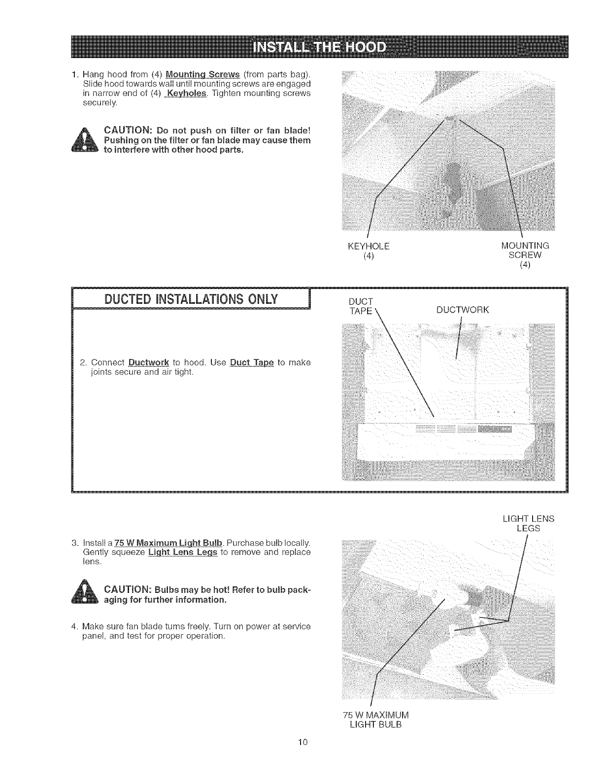
1. Hang hood from (4) Mountin_ (from parts bag).
Slide hood towards walI until mounting screws are engaged
in narrow end of (4) _. Tighten mounting screws
securely.
CAUTION: Do not push on filter or fan blade!
Pushing on the filter or fan bmade may cause them
to interfere with other hood parts.
KEYHOLE MOUNTING
(4) SCREW
(4)
2. Connect Ductwork to hood. Use Duct _ to make
joints secure and air tight.
DUCTWORK
3. Insta!I a 75 W Ma×imum Light Bulb. Purchase bulb IocaEly.
Gently squeeze L_qht Lens Le_ to remove and replace
lens.
CAUTION: Bulbs may be hot! Refer to bulb pack-
aging for further information.
4. Make sure fan blade turns freely. Turn on power at service
panel, and test for proper operation.
MGHT LENS
LEGS
75 W MAXIMUM
MGHT BULB
10
14
17
19
25
12
,, 2
9 °_-- \
3 3
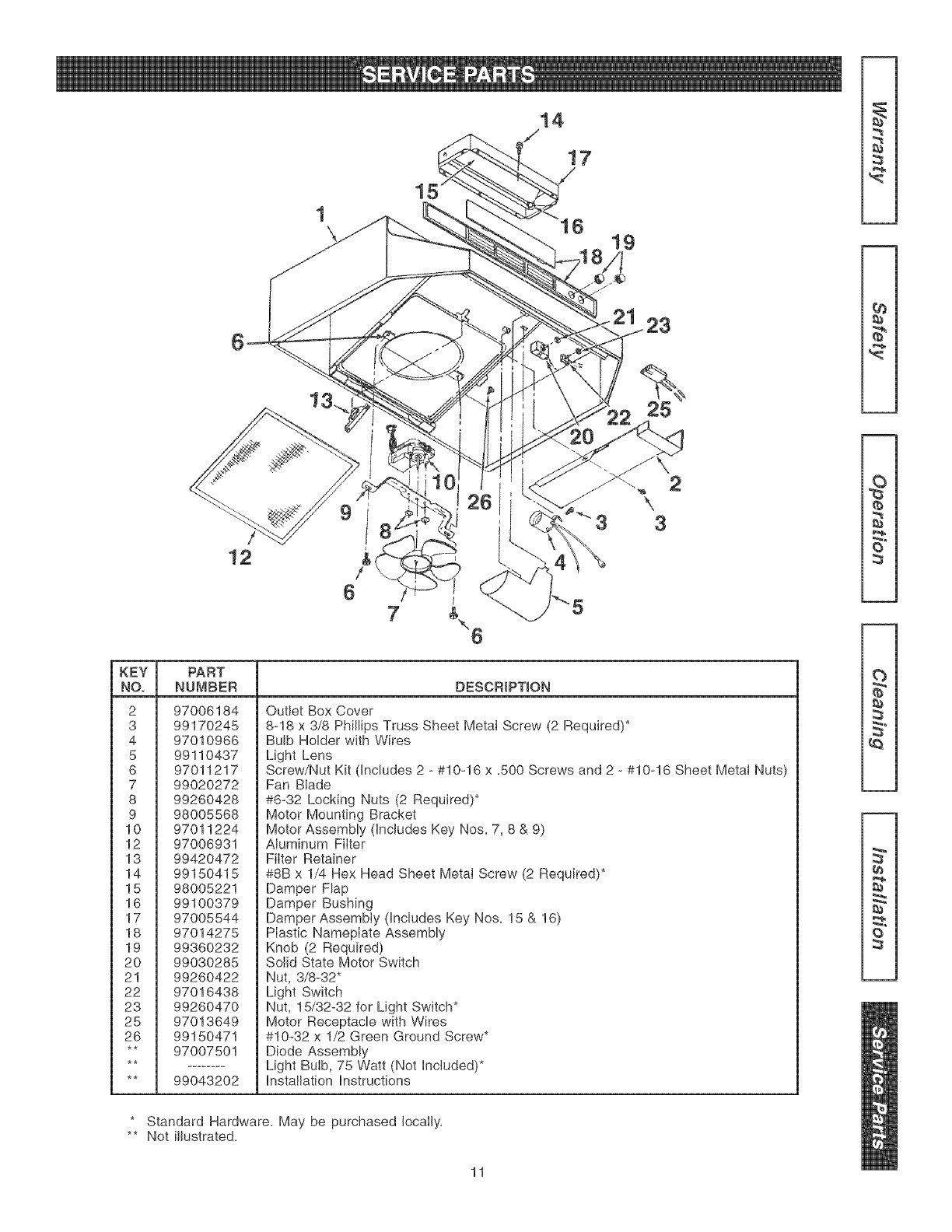
KEY PART
NOo NUMBER DESCRiPTiON
2 97006184
3 99170245
4 97010966
5 99110437
6 97011217
7 99020272
8 99260428
9 98005568
10 97011224
12 97006931
13 99420472
14 99150415
15 98005221
16 99100379
17 97005544
18 97014275
19 99360232
20 99030285
21 99260422
22 97016438
23 99260470
25 97013649
26 99150471
** 97007501
** 99043202
Outlet Box Cover
8-18 x 3/8 Phillips Truss Sheet Metal Screw (2 Required)*
Bulb Holder with Wires
Light Lens
Screw/Nut Kit dncludes 2 - #10-16 x ,500 Screws and 2 - #10-16 Sheet Metai Nuts)
Fan Blade
#6-32 Locking Nuts (2 Required)*
Motor Mounting Bracket
Motor Assembly dncludes Key Nos, 7, 8 & 9)
Aluminum Filter
Filter Retainer
#8B x 1/4 Hex Head Sheet Metai Screw (2 Required)*
Damper Flap
Damper Bushing
Damper Assembiy (Includes Key Nos, 15 & 16)
Plastic Nameplate Assembly
Knob (2 Required)
Solid State Motor Switch
Nut, 3/8-32"
Light Switch
Nut, 15/32-32 for Light Switch*
Motor Receptacle with Wires
#10-32 x 1/2 Green Ground Screw*
Diode Assembly
Light Bulb, 75 Watt (Not Included)*
Installation Instructions
2
3"
* Standard Hardware, May be purchased Iocaily,
** Not Hlustrated,
11
SECCI6N................................................................PAGINA Si dontro do 1 aflo do la focha do la instalaci6n, cualquior parto de osta
campana de cocina deja do funcionar on forma apropiada dobido a
defocto on o! material o mano do obra, Soars roparar_ la pioza afoctada
o provoorA o instalar_ una pioza nuova sin cargo.
GARANTm'A COMPLETA DE 30 DIAS EN EL ACABADO DE
PIEZAS PINTADAS O BE METAL LUSTROSO
Si dontro do !os 30 dfas de la focha de instalaci6n, el acabado do
cualquier pioza pintada o de metal lustroso do osta campana do
cocina prosonta defocto do matorial o mano de obra, Sears
srovoor_t o instalara una pioza nuova sin cargo.
EL SEBVICIO BE GABANTI'A SE OBTmENE PONI#:NDOSE EN
CONTACTO CON EL CENTBO BE SERVmCIO O
DEPARTAMENTO SEARS M_,S CEBCANO EN LOS ESTADOS
UNIDOS.
Esta garantfa es v_lida unicamonte si osto producto so oncuontra
on uso dentro do los Estados Unidos. Esta garantia Io confioro
dorochos Iogabs ospocificos y Ud. puodo tenor adom_s otros
derochos quo varian do ostado a ostado.
Sears, Roebuck and Co., Dept 817WA, Hoffman Estates,
IL 60179
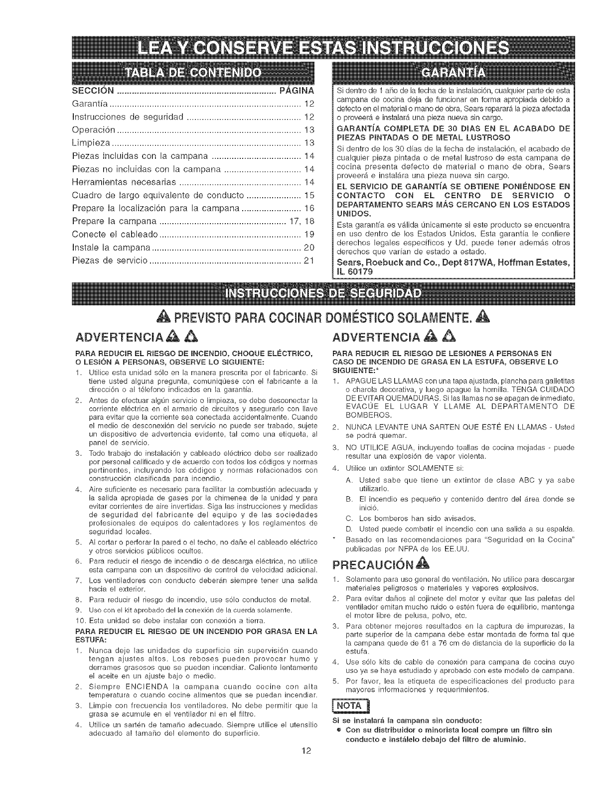
A PREVNST0PARAC0CHNARDOMC:STHC0S0LAMENTE. A
ADVERTENCmA_
PARA REDUCmR EL RIESGO DE INCENDIO, CROQUE ELE_CTRICO,
O LESl6N A PERSONAS, OBSERVE LO SIGUmENTE:
1, Utilice esta unidad s61o en la manera prescrita per el fabricante. Si
tiene usted alguna pregunta, comuniqOese con el fabricante a la
direcci6n o al t61efono indicados en la garantia.
2, Antes de efectuar algOn servicio o limpieza, se debe desconectar la
corriente electrica en el armario de circuitos y asegurarlo con Ilave
para evitar que la corriente sea conectada accidentalmente. Cuando
el medio de desconexi6n del servicio no puede ser trabado, sujete
un dispositivo de advertencia evidente, tal come una etiqueta, al
panel de servicio.
3, Todo trabajo do instalaci6n y cableado el6ctrico debe ser realizado
por personal calificado y de acuerdo con todos los c6digos y normas
pertinentes, incluyendo los c6digos y normas relacionados con
construcci6n clasificada para incendio.
4, Aire suficiente es necesario para facilitar la combusti6n adecuada y
la salida apropiada de gases por la chimenea de la unidad y para
evitar corrientes de aire invertidas. Siga las instrucciones y medidas
de seguridad del fabricante del equipo y de las sociedades
profesionales de equipos do calentadores y los reglamentos de
seguridad locales.
5, AI cortar o perforar la pared o el techo, no da_e el cableado el_ctrico
y otros servicios pOblicos ocultos.
6, Para reducir el riesgo de incendio o de descarga el6ctrica, no utilice
esta campana con un dispositivo de control de velocidad adicional.
7, Los ventiladores con conducto deber_n siempre tenet una salida
hacia el exterior.
8, Para reducir el riesgo de incendio, use s61o conductos de metal,
9, Uso con el kit aprobado del la conexi6n de la cuerda solamente.
10. Esta unidad se debe instalar con conexion a tierra.
PARA REDUCmR EL RIESGO DE UN INCENBIO POR GRASA EN LA
ESTUFA:
1, Nunca deje las unidades de superficie sin supervisi6n cuando
tengan ajustes altos. Los reboses pueden provocar humo y
derrames grasosos que se pueden incendiar. Caliente lentamente
el aceite en un ajuste bajo o medio.
2, Siempre ENCIENDA la campana cuando cocine con alta
temperatura o cuando cocine alimentos que se puedan incendiar.
3, Limpie con frecuencia los ventiladores. No debe permitir que la
grasa se acumule en el ventilador ni en el filtro.
4, Utilice un sart6n de tamaPio adecuado. Siempre utilice el utensilio
adecuado al tama[io del elemento do superficie.
12
ADVERTENCIA _
PARA REDUCIR EL RIESGO DE LESIONES A PERSONAS EN
CASO DE INCENDIO DE GRASA EN LA ESTUFA, OBSERVE LO
SIGUIENTE:*
1. APAGUE LAS LLAMAS con una tapa ajustada, plancha para galletitas
o charola decorativa, y luego apague la hornilla. TENGA CUIDADO
DE EVlTAR QUEMADURAS. Si las llamas no se apagan de inmediato,
EVACOE EL LUGAR Y LLAME AL DEPARTAMENTO DE
BOMBEROS.
2. NUNCA LEMANTE UNA SARTEN QUE ESTE EN LLAMAS -Usted
se podra quemar.
3. NO UTILICE AGUA, incluyendo toallas de cocina mojadas -puede
resultar una explosi6n de vapor violenta.
4. Utilice un extintor SOLAMENTE si:
A. Usted sabe que tiene un extintor de clase ABC y ya sabe
utilizarlo.
B. El incendio es pequePio y contenido dentro del _rea donde se
inici6.
C. Los bomberos han side avisados.
D. Usted puede combatir el incendio con una salida a su espalda.
Basado en las recomendaciones para "Seguridad en la Cocina"
publicadas pot NFPA de los EE.UU.
1. Solamente para use general de ventilaci6n. No utilice para descargar
materiales peligrosos o materiales y vapores explosivos.
2. Para evitar da[ios al cojinete del motor y evitar que las paletas del
ventilador emitan mucho ruido o est6n fuera de equilibrio, mantenga
el motor libre de pelusa, polvo, etc.
3. Para obtener mejores resultados en la captura de impurezas, la
parte superior de la campana debe estar montada de forma tal que
la campana quede de 61 a 76 cm de distancia de la superticie de la
estufa.
4. Use s61o kits de cable de conexi6n para campana de cocina cuyo
use ya se haya estudiado y aprobado con este modelo de campana.
5. Por favor, lea la etiqueta de especificaciones del producto para
mayores informaciones y requerimientos.
Si se instalara la campana sin conducto:
o Con su distribuidor o minorista EocaE compre un filtro sin
coeducto einstalelo debajo del fiEtro de aluminio,
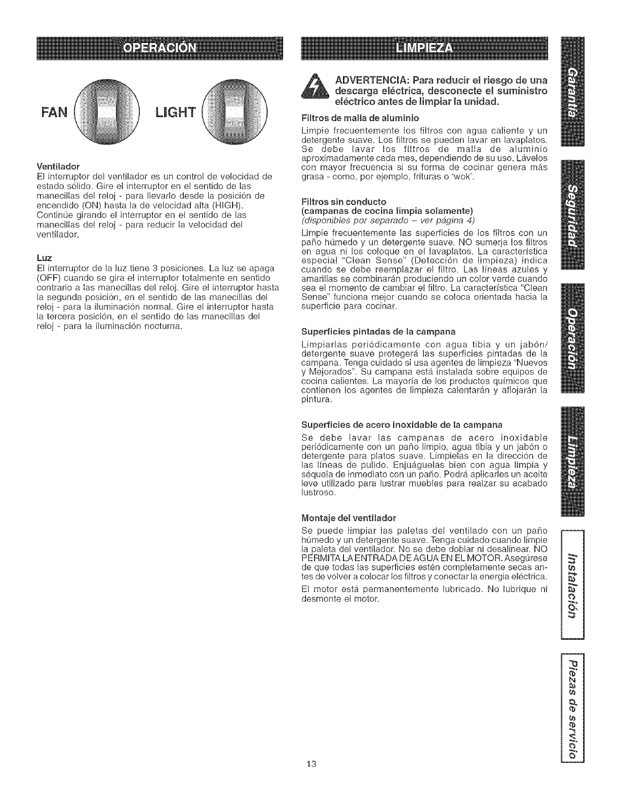
LIGHT
Venti_ador
El interruptor de! ventilador es un control de velocidad de
estado s61ido. Gire el interruptor en el sentido de Ias
manecillas del reloj - para Ilevarto desde la posici6n de
encendido (ON) hasta la de velocidad alta (HIGH).
ContinOe girando el interruptor en eI sentido de las
manecilIas del reloj -para reducir la velocidad del
ventilador.
Luz
El interruptor de la luz tiene 3 posiciones. La luz se apaga
(OFF) cuando se gira eI interruptor totalmente en sentido
contrario a Ias manecillas de! re!oj. Gire et interruptor hasta
la segunda posici6n, en el sentido de las manecillas de!
reloj - para la iluminaci6n normal. Gire el interruptor hasta
la tercera posici6n, en el sentido de Ias manecillas del
reloj - para la iluminaci6n nocturna.
_ ADVERTENCIA: Para reducir el riesgo de una
descarga el_ctrica, desconecte el suministro
electrico antes de timpiar ta unidad.
Fimtros de maria de aBuminio
Limpie frecuentemente los filtros con agua caliente y un
detergente suave. Los filtros se pueden lavar en lavaplatos.
Se debe lavar los filtros de malIa de aluminio
aproximadamente cada rues, dependiendo de su uso. LAvelos
con mayor frecuencia si su forma de cocinar genera m&s
grasa - como, pot ejemplo, frituras o 'wok'.
Fimtroe sin condacto
(campanae de cocina mimpia somamente)
(disponibles per separado -vet pagLoa 4)
Limpie frecuentemente las superficies de los filtros con un
paho h0medo y un detergente suave. NO sumerja los filtros
en agua ni los coloque en el tavaplatos. La caractedstica
especia! "Clean Sense" (Detecci6n de Iimpieza) indica
cuando se debe reemplazar et filtro. Las I(neas azules y
amarillas se combinar_n produciendo un color verde cuando
sea el momento de cambiar e! filtro. La caracter[stica "Clean
Sense" funciona mejor cuando se coloca orientada hacia la
superficie para cocinar.
Superficies pintadaa de macampana
Limp!arias periddicamente con agua tibia y un jabdn/
detergente suave proteger_ las superficies pintadas de Ia
campana. Tenga cuidado si usa agentes de Iimpieza "Nuevos
y Mejorados'. Su campana est_ instalada sobre equipos de
cocina calientes. La mayoda de los productos qu[micos que
contienen los agentes de limpieza calentaran y afiojaran la
pintura.
Superficies de acero ino×idable de la campana
Se debe Iavar las campanas de acero inoxidable
periddicamente con un paso limp!o, agua tibia y un jabdn o
detergente para platos suave. Limpielas en la direcci6n de
las I[neas de pulido. Enju_guelas bien con agua limpia y
sequela de inmediato con un paso. Podr_ aplicarles un aceite
leve utilizado para lustrar muebles para realzar su acabado
lustroso.
Montaje del ventHadol"
Se puede Iimpiar Ias paletas deI ventilado con un paso
h0medo y un detergente suave. Tenga cuidado cuando Iimpie
la paleta del ventilador. No se debe doblar ni desalinear. NO
PERMITA LA ENTRADA DE AGUA EN EL MOTOR. Aseg0rese
de que todas Ias superficies esten completamente secas an-
tes de votver a colocar los filtros y conectar la energia electrica.
El motor estb, permanentemente lubricado. No lubrique ni
desmonte el motor. O,
13
N
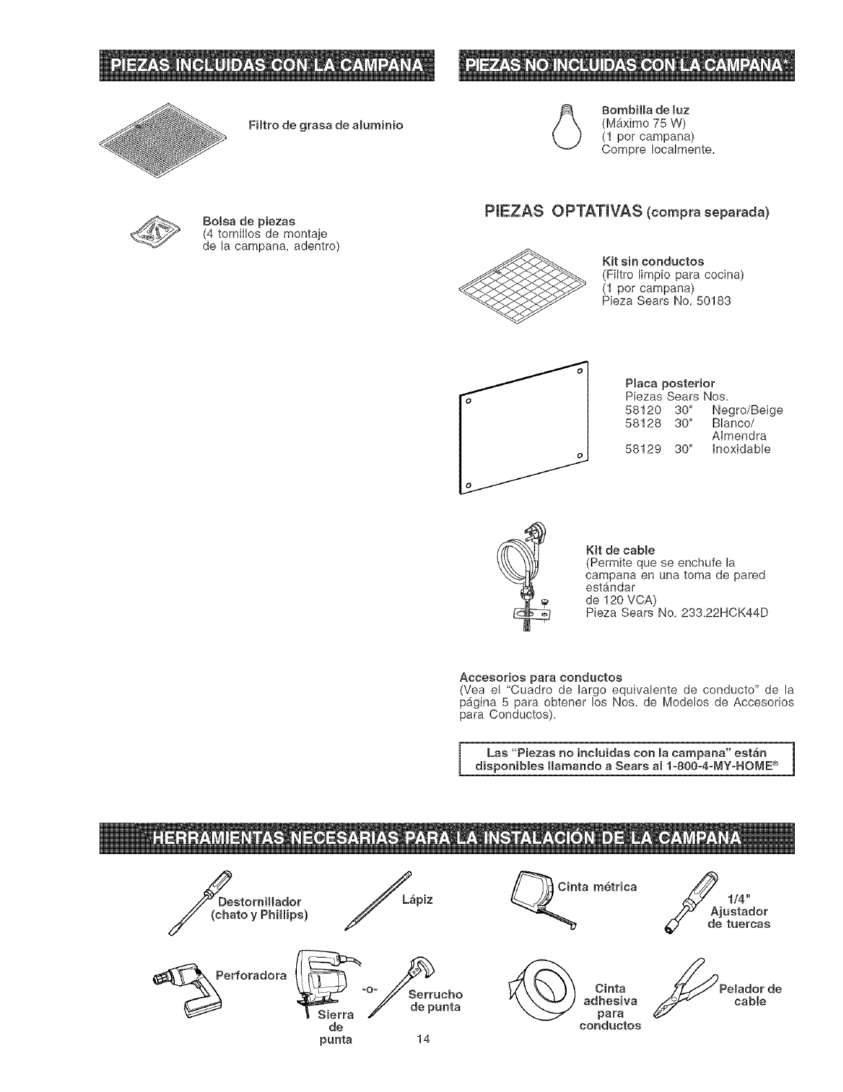
FHtro de grasa de aluminio
BombiHa de luz
(Mb.ximo 75 W)
(1 per campana)
Compre Iocalmente=
Bomsade piezas
(4 tornilIos de montaje
de la campana, adentro)
PIEZAS OPTATmVAS (compra separada)
Kit sin conductos
(Filtro limpio para cocina)
(1 per campana)
Pieza Sears No. 50183
PBaca posterior
Piezas Sears Nos=
58120 30" Negro/Beige
58128 30" Blanco/
AImendra
58129 30" hoxidable
Kit de cabBe
(Permite que se enchufe la
campana en una toma de pared
estandar
de 120 VCA)
Pieza Sears No. 233=22HCK44D
Accesorios para conductos
(Yea e! "Cuadro de largo equivalente de conducto" de la
p_gina 5 para obtener los Nos= de Modelos de Accesorios
para Conductos)=
1
Las "Piezas no incluidas con macampana" estan |
disponibmes Hamando a Sears a81-800=4-MY=HOME _> J
DeastOrniHador
to y Phillips)
erforadora
Sl_erra °°_ _serruche
_" de punta
de
punta 14
ta metrica
Cinta
adhesiva
para
conductos
Se /4''
juetador
tuereas
Pelador de
cable
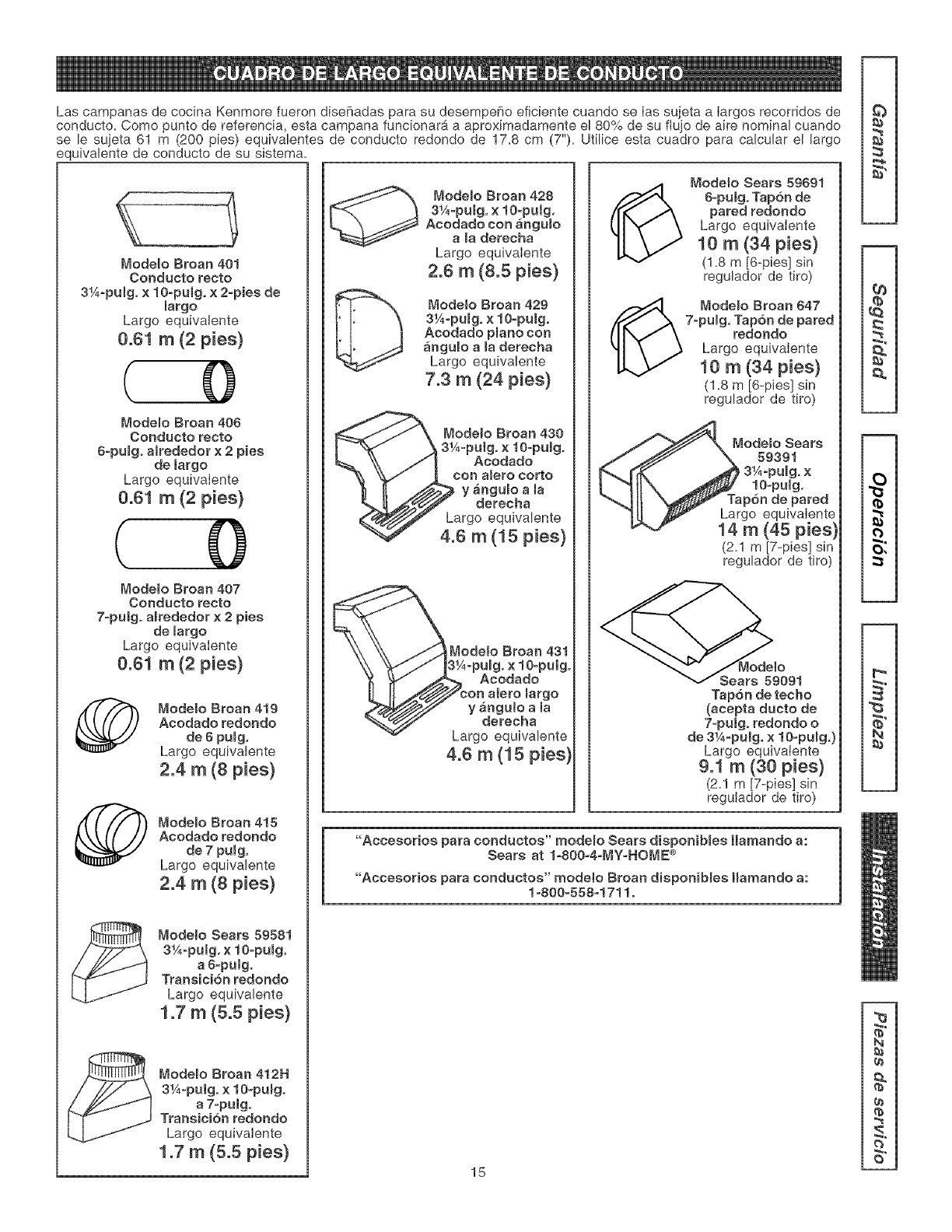
Las campanas de cocina Kenmore fueron disehadas para su desempe_o eficiente cuando se Ias sujeta a Iargos recorridos de
conducto. Como punto de referencia, esta campana funcionara a aproximadamente el 80% de su fiujo de aire nominal cuando
se le su]eta 61 m (200 pies) equivalentes de conducto redondo de 17.8 cm (7"). Utilice esta cuadro para calcular el largo
equivalente de conducto de su sistema.
Modemo Broan 401
Conducto recto
3¼-pulgo × 1O-pulg. x 2°pies de
largo
Largo equivalente
0.6t rn (2 pies}
( 0
Modelo Broan 406
Conducto recto
6-pumg° a_rededer x 2 pies
de largo
Largo equivaIente
0.61 m (2 pies}
( 0
Modelo Broan 407
Conducto recto
7-pulg° amrededor x 2 pies
de largo
Largo equivaiente
0.61 m (2 pies}
Modemo Broan 419
Acodado redondo
de 6 pumg.
Largo equivalente
2.4 m (8 pies}
Mode[o Broan 415
Acodado redondo
de 7 pumg.
Largo equivalente
2.4 m (8 pies)
ModeBo Sears 59581
3¼-pulg. x10opumg.
a 8_pulg.
TransiciTn redondo
Largo equivalente
1.7 m (5.5 pies}
Modelo Broan 412H
3¼_pulg° x 10opumg.
a 7-puig.
Transicion redondo
Largo equivalente
1.7 m (5.5 pies}
[_ Modelo Broan 428
3¼°puBg. x 10-pulg.
Acodado con angumo
a maderecha
Largo equivaiente
2.6 m (8.5 pies}
Modelo Broan 429
3¼opuBg. x 10-pulg.
Acodado pBano con
angulo ama derecha
Largo equivalente
7.3 m (24 pies}
Mode_o Bream 430
3¼-pulg. ×1O-pumg.
Acodado
con alero corto
y anguBo a la
derecha
Largo equivalente
4.6 m (15 pies}
Modelo Broan 431
-puBg. x 1O-pulg°
Acodado
on alero margo
y _ngulo a la
derecha
rgo equivalente
4.6 m (15 pies)
Mode_o Sears 59691
8-pulg. Tap6n de
pared redondo
Largo equivaIente
10 m (34 pies}
(1.8 m [6-pies] sin
regulador de tiro)
(_ Modemo Broan 647
7-pumg. Tapbn de pared
redondo
Largo equivaIente
10 m (34 pies}
(1.8 m [6-pies] sin
regulador de tiro)
ModeBo Sears
59391
3¼opulg. x
10opulg.
Tapon de pared
Largo equivaIente
14 m (45 pies}
(2.1 m [7-pies] sin
regulador de tiro)
Tapon de techo
(acepta ducto de
7°pUlgo redondo o
de 3¼°pUlgo x 10-puBg.)
Largo equivaiente
9.1 m (30 pies}
(2.1 m [7-pies] sin
regulador de tiro)
"Accesorios para conductos" rnodemo Sears disponibmes llamando a:
Sears at I_800o4oMy=HOME _>
"Accesorios para conductos" modeto Broan disponibmes Hamando a:
1-800-558-1711°
15
q)
¢a
2
(b
(.}
O,
N
N
g}
(b
¢)
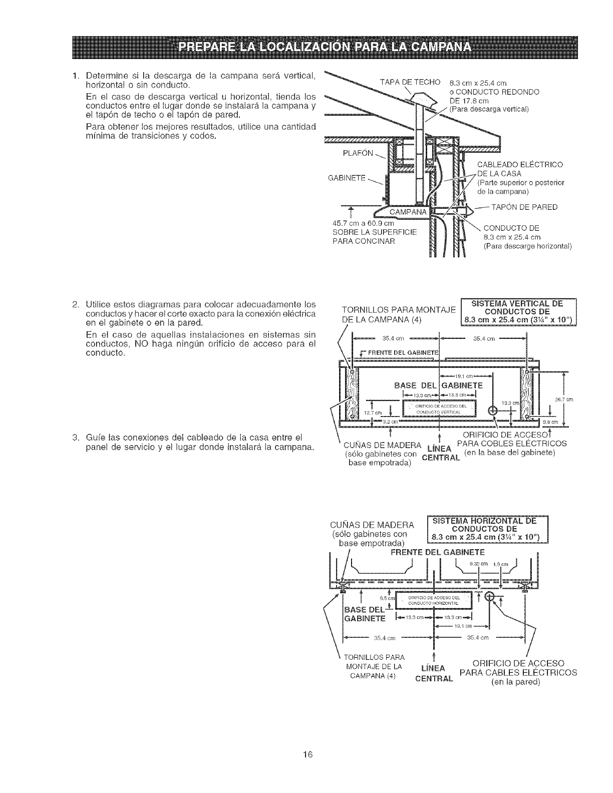
1. Determinesi ladescargadeIacampanaser_vertical,
horizontal0sinconducto. TAPADETECHO8.3cmx25.4cm
oCONDUCTOREDONDO
Enelcasodedescargavertica!u horizontal,tiendalos _ DE17.8cm
conductosentree!IugardondeseinstaIaralacampanaY_ Para descargavertical)
el tap6n de techo o el tap6n de pared.
Para obtener Ios mejores resuItados, utilice una cantidad
mfnima de transiciones y codes.
GABINETE
t
45.7 cm a 60.9 cm
SOBRELASUPERFICIE
PARACONCINAR
CABLEADO ELECTRICO
LA CASA
(Parte superior o posterior
de la campana)
_ITAPON DE PARED
CONDUCTO DE
8.3 cm x 25,4 cm
(Para descarge horizontal)
2. Utilice estos diagramas para colocar adecuadamente los
conductos y hacer e! corte exacto para la conexiCn elCctrica
en e! gabinete o en la pared.
En el caso de aquellas instalaciones en sistemas sin
conductos, NO haga ningOn orificio de acceso para el
conducto.
3. Gu[e Ias conexiones deI cabbado de Ia casa entre el
panel de servicio y el lugar donde instalara la campana.
I SISTE[v]AVERTICAL BE ]
TORNiLLOS PARA MONTAJE CONDUCTOS BE
DE LA CAMPANA (4) 8.3 cm x 25.4 cm (3_A"x 10")
35.4 cm ,_"_-_ 39.4cm"__ 35.4 cm
FRENTE DEL (_
I_
1G_A C, 1 cm_CASE eEL INE
127 Cn_ _ CONDUCF_VERT_CAL J
ORIFICIO DE ACCESOt
CUI_ASDE MADERA PARA COBLES ELECTRICOS
(sCIogabinetes con CENTRAL (en la base del gabinete)
base empotrada)
CUNAS DE MADERA
(sCIo gabinetes con
base empotrada)
SISTEMA HORIZONTAL DE
CONDUCTOS DE
8.3 cmx 25.4 cm (3_A'' x 10")
MONTAJE DE LA
CAMPANA (4)
LmNEA
CENTRAL
7
ORIFIOIO DE ACCESO
PARA CABLES ELECTRICOS
(en la pared)
16
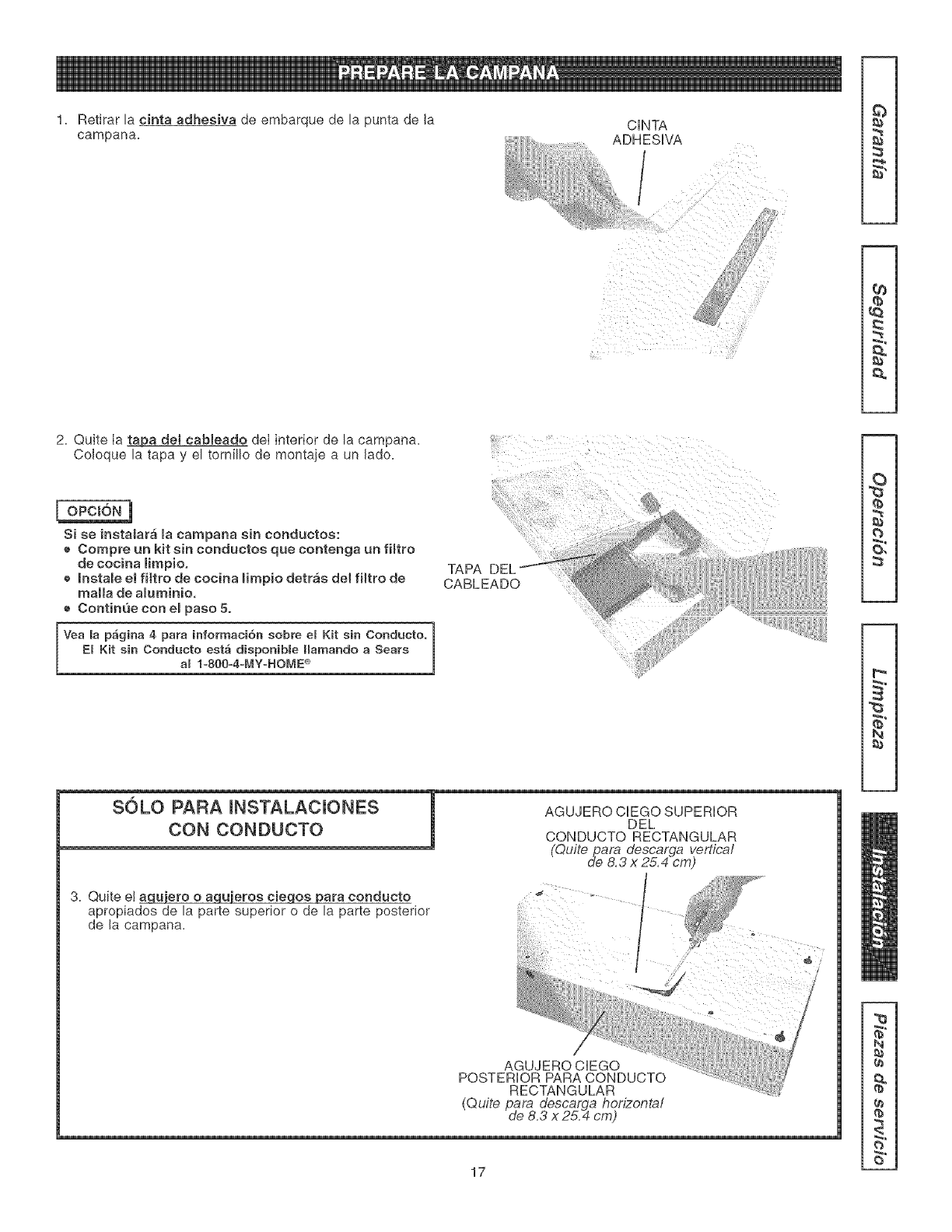
1. Redrarlacintaadhesiva de embarque de la punta de la
oampana. CINTA
i ............. ADHySIVA
}i/
_{i!i!i!_!/
8
ca
2. Quite Ia tapa dei cableado deI interior de la campana.
Coloque la tapa y el tornillo de montaje a un lade.
Si se instalara la campana sin conductos:
e Compre un kit sin conductos que contenga un fHtro
de cocina limpio.
eInstale el filtro de cocina limpio detras det filtro de
maria de aBuminio.
e Continue con empaso 5.
Vea la p_gina 4 para informaci6n sobre el Kit sin Conducto.
I El Kit sin Conducto est_ disponible Hamando a Sears
[ al I=800=4=MY=HOME®
TAPA
CABLEADO
2
p,
sS
N
3. Quite e! _ieroe cieqos para conducto
apropiados de la parte superior o de la parte posterior
de la campana.
AGUJERO CIEGO
POSTERIOR PARA CONDUCTO
RECTANGULAR
(Quite para descarga hoHzonta!
de 8.3 x25.4 cm)
17
N
q_
SOLOPARAINSTALACIONES J
m
CONCONDUCTOS j BORDEBELA
BPARTE SUPERIOR/ _,
POSTERIOR_ ,_
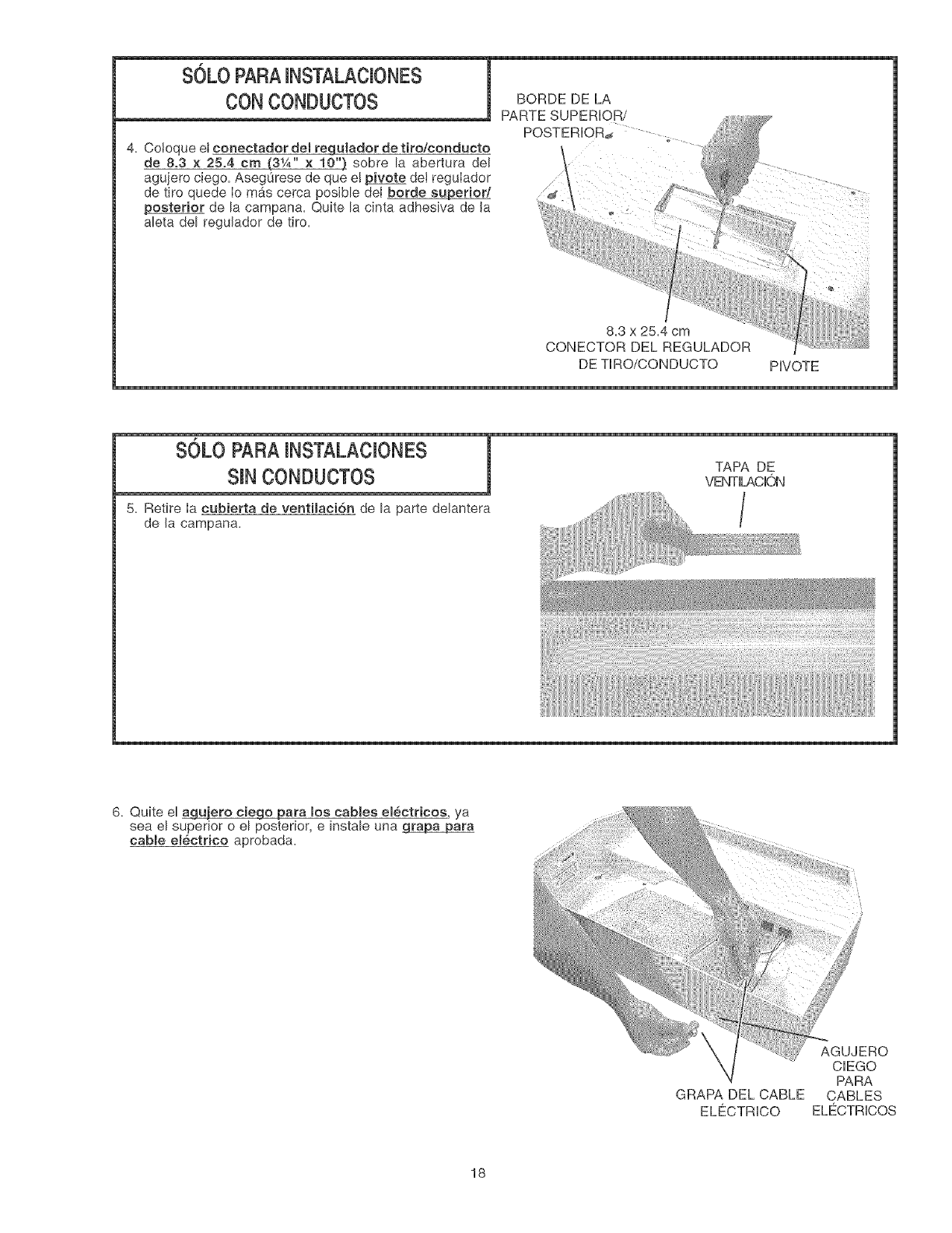
4. Cotoque et conectador det regulador de tiro/conducto
de 8.3 x 25.4 cm {'31A" × 10") sobre la abertura del
agujero ciego. AsegQrese de que e! pivote de! regulador
de tiro quede Io m_s cerca posibb dei borde superior/
posterior de la campana. Quite la cinta adhesiva de Ja
abta del reguJador de tiro.
,=!,
8.3 x 25.4 cm
CONECTOR DEL REGULADOR
DE TIRO/CONDUCTO PIVOTE
5. Retire Ia cubierta de ventlaci6n de la parte delantera
de Ja campana.
VENTILACION
/
6. Quite el _ara los cables electricos ya
sea el superior o el posterior, e instab una _ara
cable electrico aprobada.
GRAPA DEL CABLE
ELE'_CTRICO
AGUJERO
CIEGO
PARA
CABLES
ELE'_CTRICOS
18
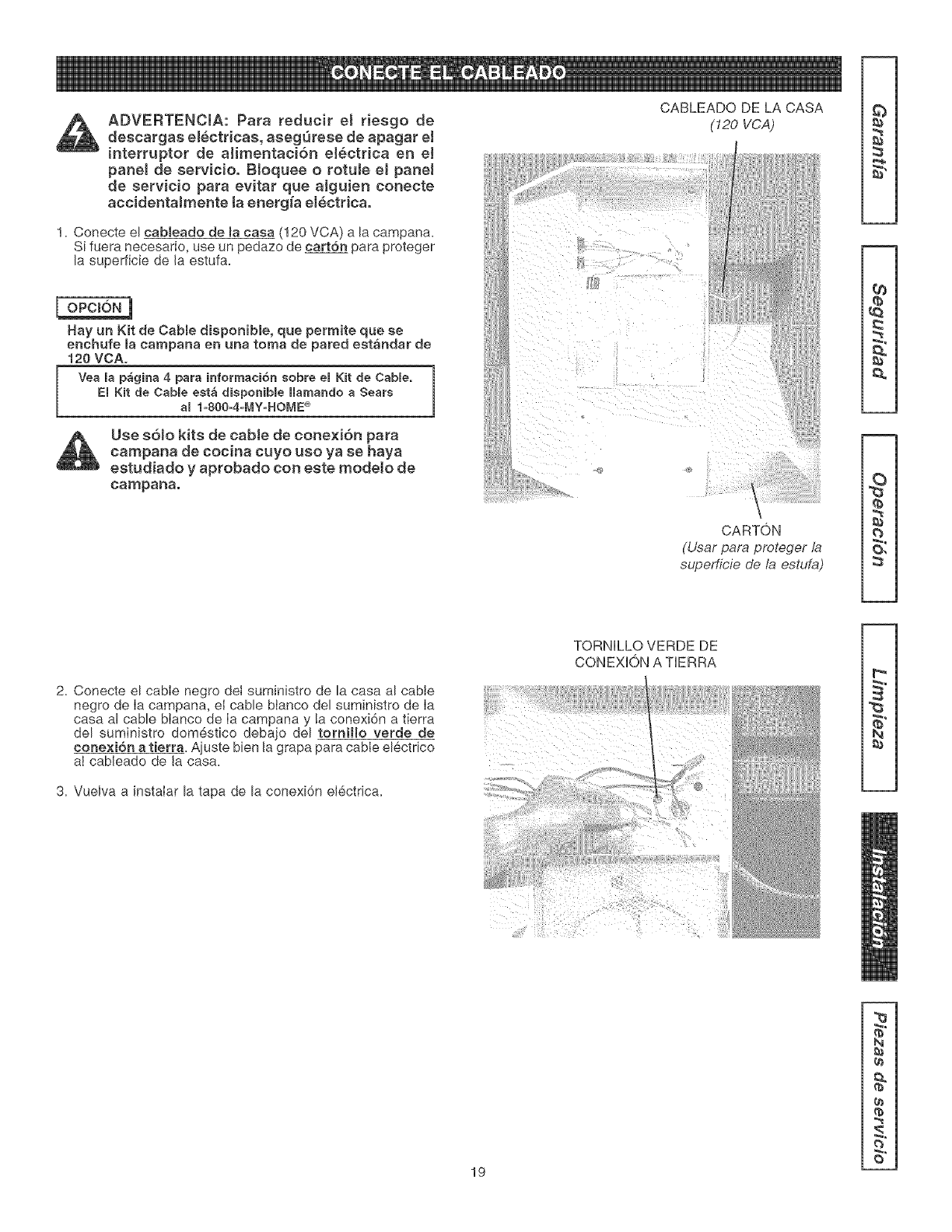
ADVERTENCIA: Para reducir el riesgo de
descargas electricas, aseg(_rese de apagar el
interruptor de aHrnentaciSn el_ctrica en e!
panel de servicio. BJoquee o _otuJe eJ paneJ
de servicio para evitar que aiguien conecte
accidentaJmente la energ{a electrica.
1= Conecte el cabteado de la caea (120 VCA) a la campana.
Si fuera necesario, use un pedazo de cart6n para proteger
la superficie de la estufa.
Hay un Kit de Cable disponible, que permite que se
enchufe la campana en una toma de pared estandar de
120 VOA.
Vea la p_gina 4 para ir#ormaci6n sobre el Kit de CaMe.
El Kit de Cable est_ disponibBe Harnando a Sears
al 1=800=4=MY=HOME®
Use s6!o kits de cabJe de conexi6n para
campana de cocina cuyo uso ya se haya
estudiado y aprobado con este modeto de
campana.
CABLEADO DE LA CASA
(120 VCA)
CARTON
(Usar para proteger la
supe_@ie de la estufa)
8
2
2. Conecte el cable negro det suministro de la casa al cable
negro de Ia campana, eI cable btanco del suministro de Ia
casa al cable blanco de Ia campana y la conexi6n a tierra
del suministro domestico debajo del torniHo verde de
conexion a tierra. Ajuste bien la grapa para cable electrico
aI cableado de la casa.
3= Vuelva a instaIar la tapa de la conexi6n el6ctrica.
TORNILLO VERDE DE
CONEXION A TERRA
i}{,iiii} } j / } i//
sS
N
19
X_
N
q_
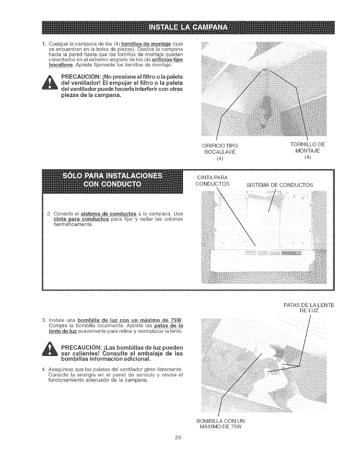
1.Cuelgueiacampanade!os(4)torniffosde rnontaje (que
se encuentran en la bolsa de piezas). Desiice la campana
hacia [a pared hasta que los tomiiios de montaje queden
conectados en el extreme angosto de los (4) orificios tipo
bocalmave. Apriete fi]amente los torniHos de montaje.
PRECAUCION: iNo presione e[ fi[tro o [a paJeta
de[ ventilador! El empujar e[ fiitro o [a paIeta
de[ ventiIador puede hacerla interferir con otras
piezas de [a campana.
ORIFICIO TIPO TORNILLO DE
BOCALLAVE MONTAJE
(4) (4)
CHNTA PARA
CONDUCTOS SISTEMA DE CONDUCTOS
2. Conecte el sistema de conductos a la campana. Use
cinta para conductos para fijar y sellar las uniones
hermeticamente.
3. Instale una bombim[a de [uz con un maximo de 75W.
Compre la bombilla [ocalmente. Apriete [as patas de [a
[ente de luz suavemente para retirar y reempiazar la lente.
PFIECAUCION: iLas bombi[[as de iuz pueden
set caJientes! ConsuJte e[ embaJaje de [as
bombi[[a$ informaci6n adiciona[.
4. AsegLirese que las paletas del ventllador glren Ilbremente.
Conecte la energ[a en el panel de servicio y revise el
funcionamiento adecuado de la campana.
PATAS DE LA LENTE
DE LUZ
BOMBILLA CON UN
M/_XIMO DE 75W
2O
14
17
19
22
,, 2
9 \
3 3
12
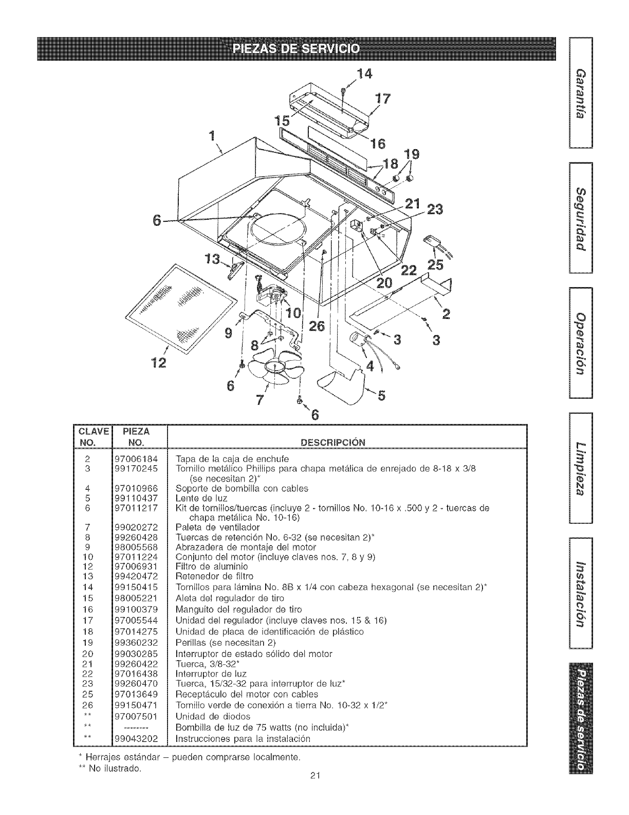
CLAVE PIEZA
NO. NO,
2 97006184
3 99170245
4
5
6
97010966
99110437
97011217
7 99020272
8 99260428
9 98005568
10 97011224
12 97006931
13 99420472
14 99150415
15 98005221
16 99100379
17 97005544
18 97014275
19 99360232
20 99030285
21 99260422
22 97016438
23 99260470
25 97013649
26 99150471
** 97007501
** 99043202
DESCRIPCtON
Tapa de ia caja de enchufe
Tomillo met#_lico Phillips para chapa metaiica de enrejado de 8-18 x 3/8
(se necesitan 2)*
Soporte de bombilla con cables
Lente de luz
Kit de tomilIos/tuercas (incluye 2 - tomillos No. 10-16 x =500y 2 - tuercas de
chapa met_lica No. 10-16)
Paleta de ventilador
Tuercas de retencidn No. 6-32 (se necesitan 2)*
Abrazadera de montaje del motor
Conjunto del motor (incluye claves nos= 7, 8 y 9)
Filtro de aluminio
Retenedor de filtro
TomilIos para I&mina No. 8B x 1/4 con cabeza hexagonal (se necesitan 2)*
Aleta del regulador de tiro
Manguito deI regulador de tiro
Unidad del regulador (incluye ctaves nos= 15 & 16)
Unidad de placa de identificacidn de plb.stico
Perillas (se necesitan 2)
Interruptor de estado s61ido del motor
Tuerca, 3/8-32"
Interruptor de luz
Tuerca, 15/32-32 para interruptor de luz*
Receptaculo de! motor con cables
TomilIo verde de conexi6n a tierra No. 10-32 x 1/2"
Unidad de diodos
Bombilla de Iuz de 75 watts (no inctuida)*
Instrucciones para la instalaci6n
O,
p-
N
O,
* Herrajes estandar -pueden comprarse Iocalmente.
** No ilustrado. 21

22

23
Your Home
i:i:i:i:i:i:i:i:i:i:i:i:i:i:i:For repair-in your home-of all major brand appliances, iiiiiiiiiiiiiiiii
i:i:i:i:i:i:i:i:i:i:i:i:i:i:i:lawnandgardenequipment, orheatingandcoolingsystems, iiiiiiiiiiiiiiiii
i:i:i:i:i:i:i:i:i:i:i:i:i:i:i: nomatterwhomadeit, nomatterwhosoldit! iiiiiiiiiiiiiiiii
iiiiiiiiiiiiiiiii
For the replacement parts, accessories and iiiiiiiiiiiiiiiii
iiiililililililililililililili owner'smanualsthatyou needtodo-it-yourself, iiiiiiiiiiiiiiiii
HHHHHHHHi
i:i:i:i:i:i:i:i:i:i:i:i:i:i:i: For Sears professional installation of home appliances iiiiiiiiiiiiiiiii
i:i:i:i:i:i:i:i:i:i:i:i:i:i:i:anditemslikegaragedooropenersandwaterheaters, iiiiiiiiiiiiiiiii
HHHHHHHHi
i:i:i:i:i:i:i:i:i:i:i:i:i:i:i: IoSO0o4oMYoHOME ® (1-8o0-469-4663} iiiiiiiiiiiiiiiii
iiiiiiiiiiiiiiiii
i:i:i:i:i:i:i:i:i:i:i:i:i:i:i: Callanytime, dayornight(U.S.A, andOanada) iiiiiiiiiiiiiiiii
HHHHHHHHi
i:i:i:i:i:i:i:i:i:i:i:i:i:i:i: www,sears,com www,sears°ca iiiiiiiiiiiiiiiii
oo,.o o iiiiiiiiiiiiiiiii
For repairof carry-initems likevacuums, lawn equipment, iiiiiiiiiiiiiiiii
iiiiiiiiiiiiiiiiiiiiiiiiiiiiiiiiiiiiand electronics, call or go on-line for the location of your nearest iiiiiiiiiiiiiiiii
iiiiiiiiiiiiiiiiii Sears?rts&Re:airOenter.
1 800 488 1222
iiiiiiiiiiiiiiiiii Call anytime, day or night (U.S.A. only)
iiiiiiiiiiiiiiiiiiiiiiiiiiiiiiiiiiii www.sears.com iiiiiiiiiiiiiiiii
iiiiiiiiiiiiiiiiii iiiiiiiiiiiiiiiii
iiiiiiiiiiiiiiiiii To purchase a protection agreement (U.S.A.) iiiiiiiiiiiiiiiii
iiiiiiiiiiiiiiiiiiormaintenanceagreement(Canada) onaproductservicedbySears: iiiiiiiiiiiiiiiii
iiiiiiiiiiiiiiiiii 1-800"827"6655 (U.S.A.) 1"800"361"6665 (Canada) iiiiiiiiiiiiiiiii
iiiiiiiiiiiiiiiiiiiiiiiiiiiiiiiiiiiiParapedirserviciodereparaci6n AuCanadapourserviceenfrangais: iiiiiiiiiiiiiiiii
iiiiiiiiiiiiiiiiii a domicilio, y para ordenar piezas °1o oL oF Y RMc
" 800 E O E iiiiiiiiiiiiiiiii
iiiiiiiiiiiiiiiiiiiiiiiiiiiiiiiiiiii1-888-SU-HOGAR sM iiiiiiiiiiiiiiiii
:::::::::::::::::::::::::::::: (1-800-533-6937)
(1-888-784-6427) www.sears.ca
TM SM
® Registered Trademark /Trademark /Sewice Mark of Sears, Roebuck and Co.
SMTM
® Marca Registrada /Marca de F_brica /Marca de Servicio de Sears, Roebuck and Co.
MCMarque de commerce /MDMarque depos6e de Sears, Roebuck and Co. © Sears, Roebuck and Co.
