Kenmore 23352602000 User Manual RANGE HOOD Manuals And Guides L0309708
KENMORE Range Hood Manual L0309708 KENMORE Range Hood Owner's Manual, KENMORE Range Hood installation guides
User Manual: Kenmore 23352602000 23352602000 KENMORE RANGE HOOD - Manuals and Guides View the owners manual for your KENMORE RANGE HOOD #23352602000. Home:Kitchen Appliance Parts:Kenmore Parts:Kenmore RANGE HOOD Manual
Open the PDF directly: View PDF ![]() .
.
Page Count: 7
OWNER'S
MANUAL
Model Nos.
C_LI_On:
Readandfoltow
allSaf_ Rulesand
Operating Instructions
beforefirstuseof0his
Product
RANGE
HOOD
o
•Safety Instructions
• Installation Instructions
• Maintenance
• Replacement Parts List
• Warranty
R626839
Sears, Roebuck and Co,, Hoffman Estates, IL 60179 U.S.A.
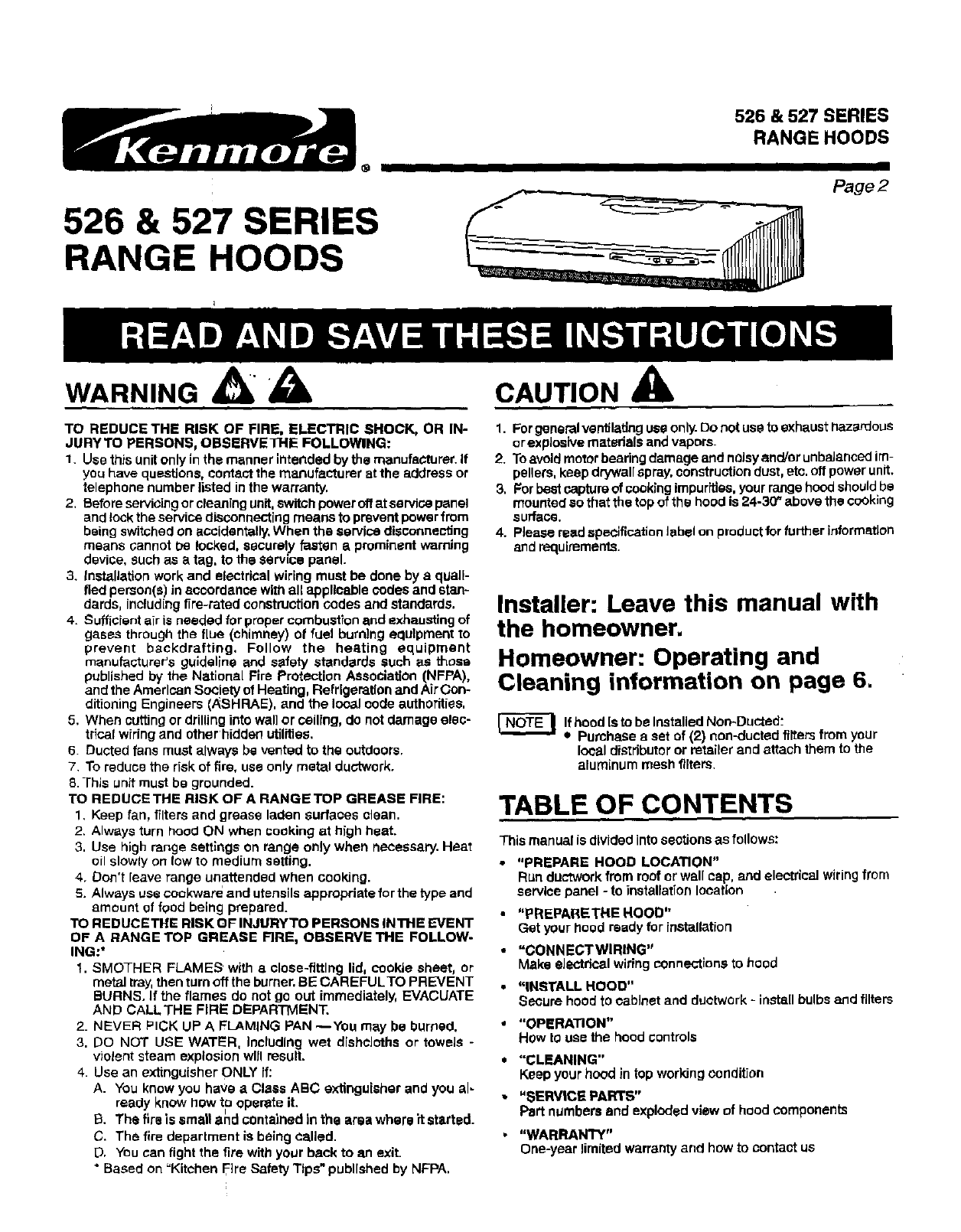
526 & 527 SERIES
RANGE HOODS
526 & 527 SERIES
RANGE HOODS
I i
Page2
WARNING A CAUTION
TO REDUCE THE RISK OF FIRE, ELECTRIC SHOCK, OR IN-
JURYTO PERSONS, OBSERVETHE FOLLOWING:
1Use this unit only in the manner intended by the manufacturer. If
you have quP._tions,contact the manufacturer at the address or
telephone number listed in the warranty,
2. Before servioing or cleaning unit, switch power offat service panel
and lockthe service disconnecting means to prevent power from
being switched on accidentally, When the service disconnecting
means cannot De looked, securely fasten a prominent warning
device, such as atag, to the service panel.
3. installation work and electrical wiring must be done by a quali-
fied person(s) in accordance with all applicable codes and stan-
dards, including fire-rated construcfion codes and standards.
4. Sufficient air is needed for proper combustion and exhausting of
gases through the flue (chimney) ot fuel burning equlpmeat to
prevent backdrafting, Follow the heating equipment
manufacturer's guideline and safety standards such as those
published by the National Fire Protection Association (NFPA),
and the American Society of Heating, Refrigeration and Air Cea-
ditioning Engineers (ASHFIAE), and the local code authorities,
5. When cuffing or drilling into wall or ceiling, do not damage elec-
trical widng and other hidden utilities.
6. Dueled fans must always be vented to the outdoors.
7. To reduce the risk of fire, use only metal ductwork.
8. This unit must be grounded.
TO REDUCETHE RISK OF A RANGE TOP GREASE FIRE:
1. Keep fan, filters and grease laden surfaoes clean.
2. AIw_,ys turn hood ON when cooking at high heat.
3. Use high range settings on range only when necessary. Heat
oil slowly on low to medium setting.
4. Don't leave range unattended when cooking.
5. Always use cockware and utensils apprapdate for the type and
amount of food being prepared.
TO REDUCE THE RISK OF INJURYTO PERSONS INTHE EVENT
OF A RANGE TOP GREASE FIRE, OBSERVE THE FOLLOW-
ING:*
1. SMOTHER FLAMES with aclose-fitting lid, cookie sheet, or
metal tray, then turn off the burner. BE CAREFULTO PREVENT
BURNS. If _e flames do not go out immediately, EVACUATE
AND CALLTHE FIR I::DEPARTMENT.
2. NEVER PICK UP A FLAMING PAN _You may be burned,
3. [30 NOT USE WATER, Including wet dishcloths or towels -
violent steam explosion will result.
4. Use an extinguisher ONLY if:
A. You know you have aClass ABC extinguisher and you al-
ready know how to operate it.
, I , , .
B. The firs is small and c0ntamed =nthe area where it started.
C. The fire department is being called.
D. You can fight the fire with your back to an exit.
* Based on "Kitchen Fire Safety Tips" published by NFPA,
1. For general ventilating use only.Do not use to exhaust hazan:JouS
or explosive matedsts and vapars_
2. Toavoid motor bearing damage and noisyend/or unbalanced im-
pellers, keep drywall spray, construction dust, etc.off power unit.
3, For best capture of cooking impure]as, your range hood shouldbe
mounted so that the top of the hood is 24-30 _ above the cooking
surface.
4. Please read specification label on product for further information
and requiremems.
Installer: Leave this manual with
the homeowner.
Homeowner: Operating and
Cleaning information on page 6.
[-I_'-C)-I-"E---|Ifhood Isto be Instailed Non-Ducted:
_* Purohase a set of (2) non-dueled filters from your
leaal distributor or retailer and attach them to the
aluminum mesh filters.
TABLE OF CONTENTS
This manual is divided into sections as follows:
•"PREPARE HOOD LOCATION"
Run ductwork from roof or wall cap, and electrical wiring from
service panel -to installation location
•"PREPARETHI= HOOD"
Get your hoed ready for installation
• "CONN ECTWIRING"
Make eJectdc81wiring connections to hood
•"INSTALL HOOD"
Secure hood to cabinet and duotwerk -install bulbs and filters
•"OPERATION"
How to use the hood controls
• "CLEANING"
Keep your hood in top working condition
"SERVICE PARTS"
Part numbersandexplodedview of hood components
"WARRANTY"
One-year limited warranty and how to contact us
®IIII
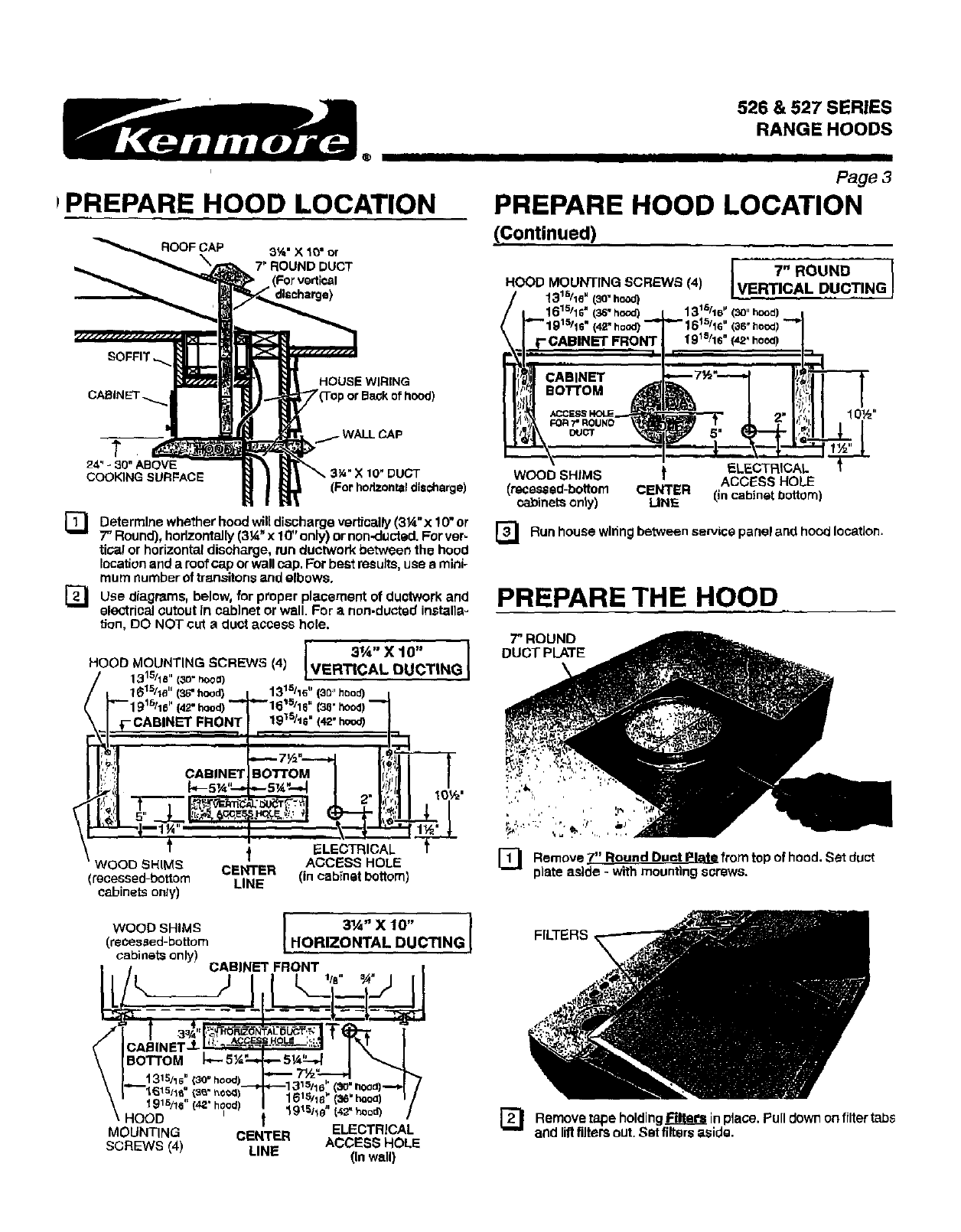
PPREPARE HOOD LOCATION
ROOFCAP 3%"X 10" or
7" ROUND DUCT
SOFFIT
HOUSE WIRING
or Ba_k of hood)
526 & 527 SERIES
RANGE HOODS
I I III
Page 3
PREPARE HOOD LOCATION
(,Continued)
I7" ROUND I
HOOD MOUNTING SCRL=WS (4) [VERTICAL DUCTING
!31_/le" (3o"howl)
161511s"(3_"hood) 131 r_/16" (_J"hood)
(36"hoax
10½"
24" -30" ABOVE
COOKING SURFACE
] Determine whether hood willdischarge vertfcallY(3¼" x 10" or
7" Round), horizontally (3_'x 10" only) or non-ductad. For ver-
tics! or horizontal discharge, tun ductwork between the hood
location and a roofcap or wall cap. For best ms u]ts,use a minio
mum number of transitons and elbows.
[_1 diagrams, below, proper placement ductwork and
Use for of
electrical cutout In cabinet or wall. For anon-duoted installs=
tJon, DO NOT cut a duct access hole.
HOOD MOUNTING SCREWS (4)
_'7 131s/1e" (3o-rbooa)
.__161silo'' (36" hood)
1915/le' (42"hood)
f-- CABINET FRONT,
Lj - I
IIit!l c,.,NET
\1.=-=-.1_1_.......
•WOOD SHI_S
(recessed-bottom
cabinets only)
31A" X 10 '°
VERTICAL DUCTING
131s116"(30"hood) i
"'161s/16" (36";lood)
19"_S/IS=(42" hood)
..... ,
.--Ta_ |_,_41I-T---T
I,
Bo'rroM IIt<',1I I
._ . # JI I I
I .t ll ,o,,,.
L_::'t31 .,L _, I{ (',l I , I
i.'_Dv-..,v,' tl _ I" Fll I I
" %'-'I 1
I_LECTRICAL _'
ACCI_SS HOLE
CENTER (in cabinet bottom)
LINE
WOOD SHIMS [ 3"/_" X10" 1
(recessed-bottom HORIZONTAL DUCTING J
cabinets only) CABINET FRONT !
l _IA" _ 1 I I
1315ti B" (3o" hood)
"_915/16" (42"hoodl
HOOD _ _915/1e " (42" hood)
ELECTRICAL
MOUNTING CENTER ACCESS HOLE
SCREWS (4) LINE (in wall)
WOOD SHIMS _ ELECTRICAL
ACCESS HOLE
(recessed-bottom CENTER (in cabinet bottom)
cabinets only) LINE.
]Run house wiring between service panel and hood IocatJon.
PREPARE THE HOOD
7" ROUND
DUCT PLATE
]Remove 7" Round Duet Plate from top of hood. Set duct
plate aside -w'dh mounting s_rsws,
FILTERS,
] Remove tape holdingRlte_ inplace. Pulldown on filtertabs
andliftfiltersout.Set filtersaside.
526 &527 SERIES
RANGE HOODS
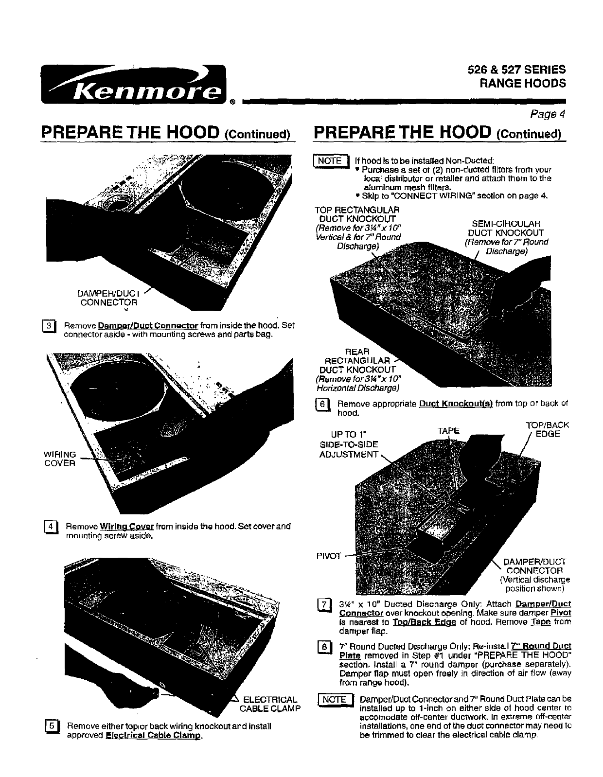
PREPARE THE HOOD (Continued)
II I I I I II
Page 4
PREPARE THE HOOD (Continued)
r'N'O'TE-_ Ifhood ls to be installed Non. Ducted:
Purchase a set of (2) non-ducted filters from your
local distributor or retailer and attach them to the
aluminum mesh filters.
_*Skip to "CONNECT WIRING" seotion on page 4.
TOP RECTANGULAR
DUCT KNOCKOUT
(Remove for 3¼ "x10"
Verb'ca/& for 7"Round
Dfsoharge_
SEMI-CIRCULAR
DUCT KNOCKOUT
(Remove for 7" Round
Discharge)
DAMPEFVDUCT I
CONNECTOR
]Remove _dDuet Connector from inside the hood. Set
connector aside - with mounting screws and parts bag.
WIRING
COVER
]Remove _ from inside the hood. Set cover and
mounting screw aside.
ELECTRICAL
CABLE CLAM P
] Remove either top, or back widng knockout and install
approved Electrical Cable Clamp.
REAR
RECTANGULAR
DUCT KNOCKOUT
(Remove for 314"x 10"
Hofizonta/ Discharge)
]Remove appropriate Duct Knockout(s} from top or back of
hood.
TOP/BACK
UPT01" _E I /EDGE
SIDE-TO-SIDE _/
ADJU
PIVOT . DAMPER/DUCT
I " CONNECTOR
'_ (Vertical discharge
.3'_ position shown)
3tA= x 10" Ducted Discharge Only: Attach DameerlDuct
over knockout opening. Make sure damper Pivot
is nearest to Top/Beck Edqe of hood, Remove _ fTom
damper flap.
]7" Round Dusted Discharge Only: Re-install 7"' Round Duc!
Plate removed in Step #1 under "PREPARE THE HOOD'
Section, Install a 7" round damper (purchase separately).
Damper flap must open freely in direction of air flow (away
from range hood),
_Damper/Duct Connector and 7" Round Duct Plate can be
insta.lled up to 1-1rich on either side of hood center to
eccomodate off-center ductwork. In extreme off-center
installations, one end of the duct connector may need to
be trimmed to clear the electrioal cable clamp,
®
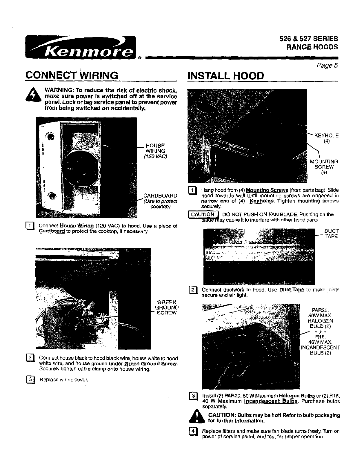
CONNECT WIRING
_b WARNING: To reduce the risk of electric shock,make sure power is switched off at the Service
panel. Lock or tag service panel to prevent power
from being switched on accidentally,
INSTALL HOOD
526 & 527 SERIES
RANGE HOODS
I
Page 5
HOUSE
WIRING
(120 VAC)
(4)
MOUNTING
SCREW
(4)
CARDBOARD
cooktop)
[_ Wiring (120 VAC) to Use a piece of
Connect House hood.
to protect the cooktop, if llecessary.
GREEN
GROUND
,/
] Connect house black to hood black wire, house white to hood
whlte wire, and house ground under _[een Ground Screw,
Securely tighten cable clamp onto house wiring.
E_ Replacewiringcover.
]Hang hood from (4) Mountinq Sorew_ (from parts bag). Slide
hood towards wa!l until mounting screws are engaged in
narrow end of (4) e..._9.y_. Tighten mounting screws
securely.
_DO NOT PUSH ON FAN BLADE. Pushing on the
ay cause itto interfere with other hood parts.
DUCT
] Connect ductwork to hood. Use .DuctT_ to make joints
secure and air tight.
_=_,,_,--_ . , ..-, z 50W MAX.
:.._..,. HALOGEN
BULB (2)
.0r o
R16,
40W MAX.
INCANDESCENT
BULB (2)
[_ (2) Haloqsn Bulbs or (2) 6,
Install PAR20, 50 W Maximum R1
40 W Maximum Incande.eeent Bulbs, Purchase bulbs
separately.
_lb AUTION: Bulbs may be hotl Refer to bulb packaging
for further information.
]tilters and make fan blade turns Turn
Replace sure freely. OR
power at service panel, and test for proper operation.
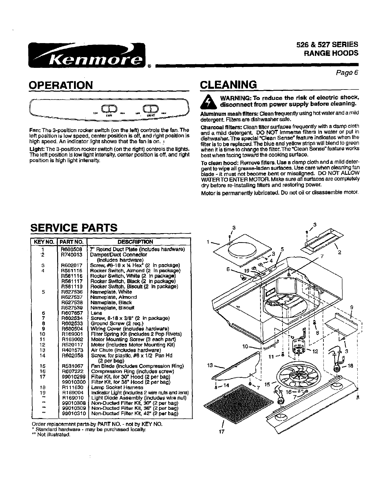
OPERATION
Fan; The 3-position rocker switch (on the left) controls the fan. The
left position is low speed, center position is off, and r?ght position is
high speed. An ind[ceter light shows that the fan Is on..=
Light: The 3-position rocker switch (on the right) ocntrols the lights.
The left position fs low light intensity,center position is off, and right
position is hfgh light intensity.
526 & 527 SERIES
RANGE HOODS
CLEANING
I
Page6
WARNING: To reduce the risk of electric shock,disconnect from power supply before cleaning.
Aluminum mesh filters: Clean frequently using hot water and amild
detergent. Filters are dishwasher safe,
Charcoal filters: Clean filler surfaces frequently with s damp cloth
and _ rnild detergent. DO NOT immeme filters in water or put in
dishwasher.The special "Clean Sense" feature Indlostes when the
filter isto be replaced. The blue and yellow stdps will blend to green
when itis time to change the filter.The "Clean Sense" feature works
best when facing toward the oooking surface,
To clean hood: Remove fillers, Use adamp cloth and a mild deter-
gentto wfpe all grease.laden surfaces. Use care when cleaning fan
blade - it must not become bent or mlsaligned. DO NOT ALLOW
WATER TO ENTER MOTOR. Make sure all surfaces are completely
dry before re-installing filters and restoring power.
Motor is permanently lubricated. Do not oil or disassemble motor.
SERVICE PARTS
KEYNO,
1
2
8
4
5
6
7
8
9
10
11
12
13
14
15
16
17
16
19
PART NO,
R680508
R740013
R602017
R561115
R561116
R561117
R561119
I R627536
R627537
R627538
1:1627539
R607857
R602£_14
R602533
R680504
R169001
R169{)02
RS201 t 7
R401573
R602058
R531067
R6it7222
99010299
99010300
Rl11630
R169004
R169010
99010308
99010309
99010310
DESCRIPTION
7" Round Duct Plate (includeshardware)
Damper/Duct Conner_tor
(Includes hardware)
Screw, #8-18 xIA He.x*(2 in package)
Rocker Swffch. Almond (2 fn paoksge)
Rocker Switch.White (2 in package)
Rocker Switch, Black (2 in package)
Rocker Switch. Blscull (2 In package)
Nameplste, White
Nameplate, Almond
Nameplate, Black
Nameplate, Biscuit
Lens
!Screw, 8-t8 x 3/8" (2 in package)
Ground Screw (2 req.)
W]fing Cover (includes hardware)
Rlter Spring Kit (Includes2 Pop Rivets)
Motor Mounting Screw (3 each part)
Motor (includes Motor Mounting Kit)
Air Chute (includes hardware)
Screw.for plastlo, #8 x 1/2 Pan Hd
(2 per bag)
Fan Blade (includes Compression Rfng)
Cempression Ring (includesscrew)
Filter K_ for 30" Hood (2 per bag)
Filter Kit, for 36" Hood (2 per beg)
Lamp Socket Hemeas
Indica_r Ught (includes2 wirenutsandlens)
Light Diode Assembly (includeswire nut)
Non.Ducted Filter Kit, 3(7*(2 per bag)
Non-Ductsd Filter Kit, 36" (2 per bag)
Non-Dusted Filter Kit,42" (2 par bag)
I
I i
I
Order replacement parts,by PART NO. - not by KEY NO. /
*Standard hardware -may be purchased locally. 17
"* Not i[lustrated.
WARRANTY
FULLTHREE YEAR WARRANTY ON PARTS
526 & 527 SERIES
RANGE HOODS
II I I
Page 7
If within 3 years from the date of installation, any part of this range hood fails to function properly due to a defect in
material or workmanship, Sears will repair the part or furnish and install anew part, free of charge.
FULL 3g-DAY WARRANTY ON FINISH ON PAINTED OR BRIGHT METAL PARTS
If within 30 days from the date of installation, the finish on any painted or bright metal parts of this range hood is
defective in material or workmanship, Sears will furnish and install a new part, free of charge.
WARRANTY SERVICE IS AVAILABLE BY CONTACTING THE NEAREST SEARS SEVICE CENTER/DEPARTMENT
IN THE UNITED STATES,
This warranty applies only while this product is in use in the United States. This warranty gives you specific legal rights
and you may have other rights which vary from state to state.
Sears, Roebuck and Co,, Dept 817WA, Hoffman Estates, IL 60179
