Kenmore 41788042700 User Manual DRYER Manuals And Guides L0709072
KENMORE Residential Dryer Manual L0709072 KENMORE Residential Dryer Owner's Manual, KENMORE Residential Dryer installation guides
User Manual: Kenmore 41788042700 41788042700 KENMORE DRYER - Manuals and Guides View the owners manual for your KENMORE DRYER #41788042700. Home:Laundry & Garment Care Parts:Kenmore Parts:Kenmore DRYER Manual
Open the PDF directly: View PDF ![]() .
.
Page Count: 24
I
I
stallati
structi
®
instrucci
instal
I
Sears, Roebuck and Co., Hoffman Estates, IL 60179 U.S.A. P/N 134941300 (0708)
CONTENTS
Pre-lnstallation Requirements .......................................................................................................................................... 2
Electrical Requirements .................................................................................................................................................. 3
Exhaust System Requirements ...................................................................................................................................... 3-4
Gas Supply Requirements ............................................................................................................................................ 4-5
Location of Your Dryer.................................................................................................................................................... 5
Rough-In Dimensions ..................................................................................................................................................... 6
Mobile Home Installation ............................................................................................................................................... 7
Unpacking ................................................................................................................................................................... 7
Reversing Door Swing ................................................................................................................................................. 8-9
Electrical Installation .................................................................................................................................................... I 0
Grounding Requirements .............................................................................................................................................. I 0
Electrical Connections--3-wire ....................................................................................................................................... 11
Electrical Connections--4-wire ........................................................................................................................................ 11
Gas Connection ............................................................................................................................................................ 12
General Installation ....................................................................................................................................................... 12
Replacement Parts........................................................................................................................................................ 12
Espahol .................................................................................................................................. 13-24
SAFETY INSTRUCTIONS
Before beginning installation, carefully read these instructions. This will simplify the installation and ensure the
dryer is installed correctly and safely. Leave these instructions near the Dryer after installation for future reference.
NOTE: The electrical service to the Dryer must conform with local codes and ordinances and the latest edition of the National
Electrical Code, ANSI/NEPA70, or in Canada, the Canadian electrical code C22.1 part 1.
NOTE: The gas service to the Dryer must conform with local codes and ordinances and the latest edition of the National Fuel
Gas Code ANSI Z223.1, or in Canada, CAN/ACG B149.1-2000
NOTE: The Dryer is designed under ANSI Z 21.5.1 or ANSI/UL 2158 - CAN/CSA C22.2 No. 112 (latest editions) for HOME USE
only. This Dryer is not recommended for commercial applications such as restaurants or beauty salons, etc.
For your safety the information in this manual must be followed to minimize the risk of fire or explosion or to
prevent property damage, personal injury or loss of life.
Do not store or use gasoline or other flammable vapors and liquid in the vicinity of this or any other appliance.
- WHATTODOIFYOUSMELL GAS
.Do not try to light any appliance.
. Do not touch any electrical switch; do not use any phone in your building.
. Clear the room, building or area of all occupants.
. Immediately call your gas supplier from a neighbor's phone. Follow the gas supplier's instructions.
. If you cannot reach your gas supplier, call the fire department.
Installation and service must be performed by a qualified installer, service agency or the gas supplier.
PRE-INSTALLATION REQUIREMENTS
Tools and Materials Required for installation:
I. Phillips head screwdriver.
2. Channel-lock adjustable pliers.
3. Carpenter's level.
4. Flat or straight blade screwdriver.
5. Duct tape.
6. Rigid or flexible metal 4 inch (10.2 cm) duct.
7. Vent hood.
8. Pipe thread sealer (Gas).
9. Plastic knife.
ELECTRICAL REQUIREMENTS
i ELECTRICDryer
CIRCUIT- Individual 30 amp. branch circuit fused with 30
amp. time delay fuses or circuit breakers.
Use separately fused circuits for washers and dryers, and DO
NOToperate a washer and a dryer on the same circuit.
POWER SUPPLY- 3 wire or 4-wire, 240 volt, single phase, 60
Hz, Alternating Current.
POWER SUPPLY CORD KIT - The dryer MUST employ a 3-
conductor power supply cord NEMA 10-30 type SRDTrated at
240 volt AC minimum, 30 amp., with 3 open end spade lug
connectors with upturned ends or closed loop connectors and
marked for use with clothes dryers.
WARNING -Risk of Shock. Appliance grounded to neutral
conductor through a link. Grounding through the neutral link is
prohibited for (1) New branch circuit installations (2) mobile
homes; (3) recreational vehicles; and (4) areas where local codes
do not permit grounding through the neutral, (1) disconnect the
link from the neutral, (2) use grounding terminal or lead to
ground appliance in accordance with local codes and (3) connect
neutral terminal or lead to branch circuit neutral in usual manner
(if the appliance is to be connected by means of a cord kit, use
4-conductor cord for this purpose). USECOPPERCONDUCTOR
ONLY. The dryer MUST employ a 4-conductor power supply
cord NEMA 14-30 type SRDT or ST (as required) rated at 240
volt AC minimum, 30 amp., with 4 open end spade lug
connectors with upturned ends or closed loop connectors and
marked for use with clothes dryers. See ELECTRICAL
CONNECTIONS FORA 4-WIRE SYSTEM.
(Canada - 4-wire power supply cord is installed on dryer.)
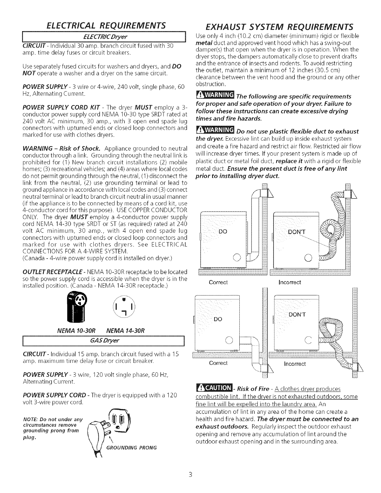
OUTLET RECEPTACLE- NEMA 10-30R receptacle to be located
so the power supply cord is accessible when the dryer is in the
installed position. (Canada - NEMA 14-30R receptacle.)
NEMA 10-30R NEMA 14-30R
GASDryer
CIRCUIT- Individual I 5 amp. branch circuit fused with a 15
amp. maximum time delay fuse or circuit breaker.
POWER SUPPLY- 3 wire, 120 volt single phase, 60 Hz,
Alternating Current.
POWER SUPPLY CORD - The dryer is equipped with a 120
volt 3-wire power cord.
f_
NOTE: Do not under any _.._ {_ _ _
circumstances remove
grounding prong from
plug.
G PRONG
EXHAUST SYSTEM REQUIREMENTS
Use only 4 inch (10.2 cm) diameter (minimum) rigid or flexible
metalduct and approved vent hood which has a swing-out
damper(s) that open when the dryer is in operation. When the
dryer stops, the dampers automatically close to prevent drafts
and the entrance of insects and rodents. To avoid restricting
the outlet, maintain a minimum of 12 inches (30.5 cm)
clearance between the vent hood and the ground or any other
obstruction.
The following are specific requirements
for proper and safe operation of your dryer. Failure to
follow these instructions can create excessive drying
times and fire hazards.
Do not use plastic flexible duct to exhaust
the dryer. Excessivelint can build up inside exhaust system
and create a fire hazard and restrict air flow. Restricted air flow
will increase dryer times. If your present system is made up of
plastic duct or metal foil duct, replace it with a rigid or flexible
metal duct. Ensure the present duct is free of any lint
prior to installing dryer duct.
_i#iiiii!
i ¸¸¸¸¸¸¸¸Do
Correct
DON'T
©
Incorrect
DO
ii
©
Correct
C
Incorrect
_- Risk of Fire - A clothes dryer produces
combustible lint. If the dryer is not exhausted outdoors, some
fine lint will be expelled into the laundry area. An
accumulation of lint in any area of the home can create a
health and fire hazard. The dryer must be connected to an
exhaust outdoors. Regularly inspect the outdoor exhaust
opening and remove any accumulation of lint around the
outdoor exhaust opening and in the surrounding area.
Do not allow combustible materials (for
example: clothing, draperies/curtains, paper) to come in
contact with exhaust system. The dryer MUST NOT be
exhausted into a chimney, a wall, a ceiling, or any concealed
space of a building which can accumulate lint, resulting in a fire
hazard.
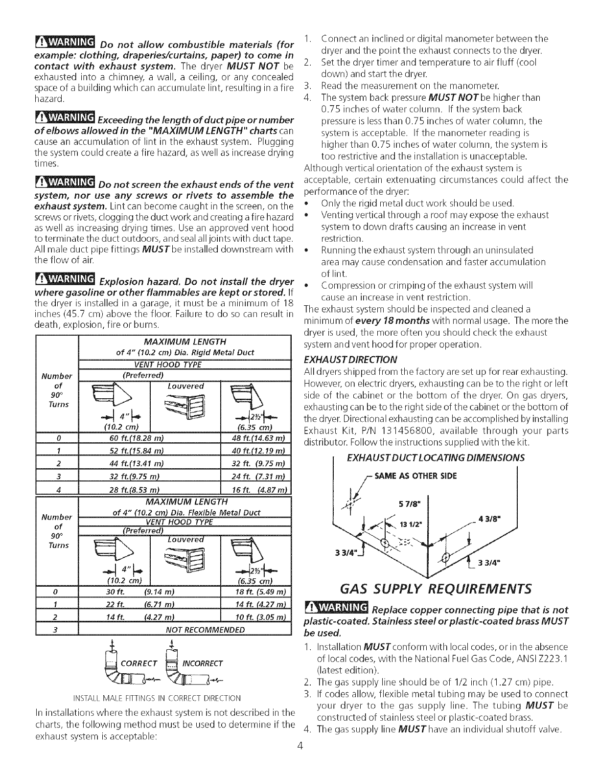
Exceeding the length of duct pipe or number
of elbows allowed in the "MAXIMUM LENGTH" charts can
cause an accumulation of lint in the exhaust system. Plugging
the system could create a fire hazard, as well as increase drying
times.
Do not screen the exhaust ends of the vent
system, nor use any screws or rivets to assemble the
exhaust system. Lint can become caught in the screen, on the
screwsor rivets, clogging the duct work and creating afire hazard
as well as increasing drying times. Use an approved vent hood
to terminate the duct outdoors, and seal alljoints with duct tape.
All male duct pipe fittings MUSTbe installed downstream with
the flow of air.
Explosion hazard. Do not install the dryer
where gasoline or other flammables are kept or stored. If
the dryer is installed in a garage, it must be a minimum of 18
inches (45.7 cm) above the floor. Failure to do so can result in
death, explosion, fire or burns.
Number
of
90 °
Turns
0
1
2
3
4
Number
of
90 °
Turns
0
1
2
3
MAXIMUM LENGTH
of 4" 110.2 cm) Dia. Rigid Metal Duct
VENT HOOD TYPE
(Preferred)
Louvered
(10.2 cm)
60 ft.(18.28 m)
52ft.(IS.84m)
44 ft.113.41 m)
32ft.(9.zsm)
28 ft.(8.53 m)
MAXIMUM LENGTH
of 4" (10.2 cm) Dia. Flexible Metal Duct
VENT HOOD TYPE
(Preferred)
(10.2 cm)
3Oft. (9.14 m)
22 ft. (6.71 m}
14 ft. (4.27 m)
NOT RECOMMENDED
2_/2'_.
(6.35 cm)
48 ft.114.63 m)
40 ft.(12.19 In)
32ft. 19.75m)
24ft. {7.31m)
16ft. (4.87m)
(6.35 cm)
18 ft. (5.49 m)
14 ft. (4.27 m)
10 ft. (3.05 m)
INSTALLMALEFITTINGSINCORRECTDIRECTION
In installations where the exhaust system is not described in the
charts, the following method must be used to determine if the
exhaust system is acceptable:
I. Connect an inclined or digital manometer between the
dryer and the point the exhaust connects to the dryer.
2. Set the dryer timer and temperature to air fluff (cool
down) and start the dryer.
3. Read the measurement on the manometer.
4. The system back pressure MUSTNOT be higher than
0.75 inches of water column. If the system back
pressure is lessthan 0.75 inches of water column, the
system is acceptable. If the manometer reading is
higher than 0.75 inches of water column, the system is
too restrictive and the installation is unacceptable.
Although vertical orientation of the exhaust system is
acceptable, certain extenuating circumstances could affect the
performance of the dryer:
• Only the rigid metal duct work should be used.
• Venting vertical through a roof may expose the exhaust
system to down drafts causing an increase in vent
restriction.
• Running the exhaust system through an uninsulated
area may cause condensation and faster accumulation
of lint.
• Compression or crimping of the exhaust system will
cause an increase in vent restriction.
The exhaust system should be inspected and cleaned a
minimum of every 18months with normal usage. The more the
dryer is used, the more often you should check the exhaust
system and vent hood for proper operation.
EXHAUST DIRECTION
All dryers shipped from the factory are set up for rear exhausting.
However, on electric dryers, exhausting can be to the right or left
side of the cabinet or the bottom of the dryer. On gas dryers,
exhausting can be to the right side of the cabinet or the bottom of
the dryer. Directional exhausting can be accomplished by installing
Exhaust Kit, P/N 131456800, available through your parts
distributor. Follow the instructions supplied with the kit.
EXHAUST DUCT LOCATING DIMENSIONS
I/SAME AS OTHER SIDE
I _'}_ ./" 5 718"
k. /_,31=j
GAS SUPPLY REQUIREMENTS
Replace copper connecting pipe that is not
plastic-coated. Stainless steel or plastic-coated brass MUST
be used.
I. Installation MUSTconform with local codes, or in the absence
of local codes, with the National Fuel Gas Code, ANSI Z223.1
(latest edition).
2. The gas supply line should be of 1/2 inch (1.27 cm) pipe.
3. If codes allow, flexible metal tubing may be used to connect
your dryer to the gas supply line. The tubing MUST be
constructed of stainless steel or plastic-coated brass.
4. The gas supply line MUSThave an individual shutoff valve.
4
5. A 1/8 inch (0.32 cm) N.P.T.plugged tapping, accessible for test gauge connection, MUST be installed immediately upstream
of the gas supply connection to the dryer.
6. The dryer MUST be disconnected from the gas supply piping system during any pressure testing of the gas supply piping system
at test pressures in excess of 1/2 psig (3.45 kPa).
7. The dryer MUST be isolated from the gas supply piping system during any pressure testing of the gas supply piping system
at test pressures equal to or lessthan
1/2 psig (3.45 kPa).
LOCATION OF YOUR DRYER
DO NOT INSTALL YOUR DRYER:
I. In an area exposed to dripping water or outside weather conditions.
2. In an area where it will come in contact with curtains, drapes, or anything that will obstruct the flow of combustion and
ventilation air.
3. On carpet. Floor MUSTbe solid with a maximum slope of I inch (2.54 cm).
INSTALLATION IN RECESSOR CLOSET
1. A dryer installed in a bedroom, bathroom, recessor closet, MUSTbe exhausted outdoors.
2. No other fuel burning appliance shall be installed in the same closet as the Gasdryer.
3. Your dryer needs the space around it for proper ventilation.
DO NOT install your dryer in a closet with a solid door.
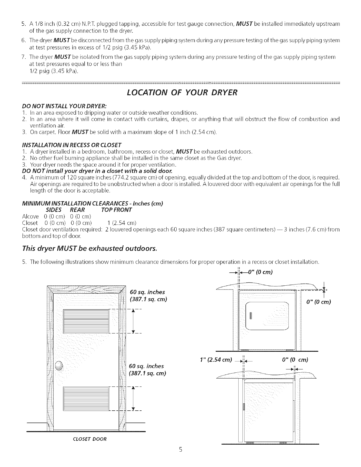
4. A minimum of 120 square inches (774.2 square cm) of opening, equally divided at the top and bottom of the door, is required.
Air openings are required to be unobstructed when a door is installed. A Iouvered door with equivalent air openings for the full
length of the door is acceptable.
MINIMUM INSTALLATION CLEARANCES -Inches (cm)
SIDES REAR TOP FRONT
Alcove 0(0cm) 0(0cm)
Closet 0 (0 cm) 0 (0 cm) 1 (2.54 cm)
Closet door ventilation required: 2 Iouvered openings each 60 square inches (387 square centimeters) -- 3 inches (7.6 cm) from
bottom and top of door.
This dryer MUST be exhausted outdoors.
5. The following illustrations show minimum clearance dimensions for proper operation in a recess or closet installation.
II
---_ii_" (0 cm)
li
0" (Ocm)
II
,, o"(o cm)
1" (2.54 cm) _11 _
II ii
II _11 _
CLOSET DOOR
48.5"
(123.19cm)
l
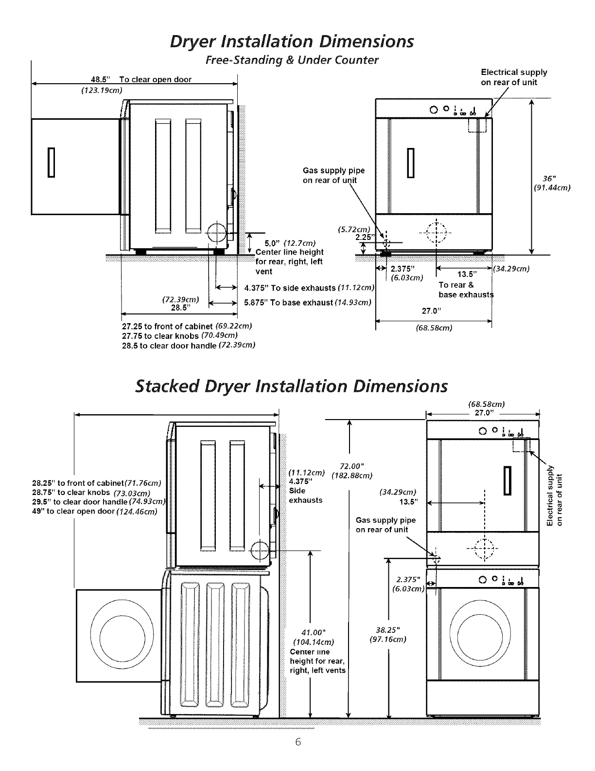
Dryer Installation Dimensions
Free=Standing & Under Counter
To clear open door
(72.39cm)
28.5"
Gas supply pipe
on rear of unit
\
(5. 72 cm)
2.25"
5.0" (12.7cm)
Center line height
rear, right, left ;_:!::F;;F
vent
4.375" To side exhausts (11.12cm)
5.875" To base exhaust (14.93cm)
27.25 to front of cabinet (69.22cm)
27.75 to clear knobs (70.49cm)
28.5 to clear door handle (72.39cm)
0 o ,'_,_ #
l
_ -p
|(6.03cm) ! 13.5"
To rear &
base exhaus
27.0"
q
(68.58cm)
Electrical supply
on rear of unit
/
36"
"91.44cm)
(34.29cm)
Stacked Dryer Installation Dimensions
T
72.00"
(11.12cm) (182.88cm)
4.375"
Side
exhausts
41.00"
(104.14cm)
Center line
height for rear,
right, left vents
1
28.25" to front of cabinet(71.76cm)
28.75" to clear knobs (73.03cm)
29.5" to clear door handle
49" to clear open door (124.46cm)
9
(34.29cm) !
13.5"
Gas supply pipe
on rear of unit
T "_i•
38.25"
(97.16cm)
(68.58cm)
27.0"
LU O
6
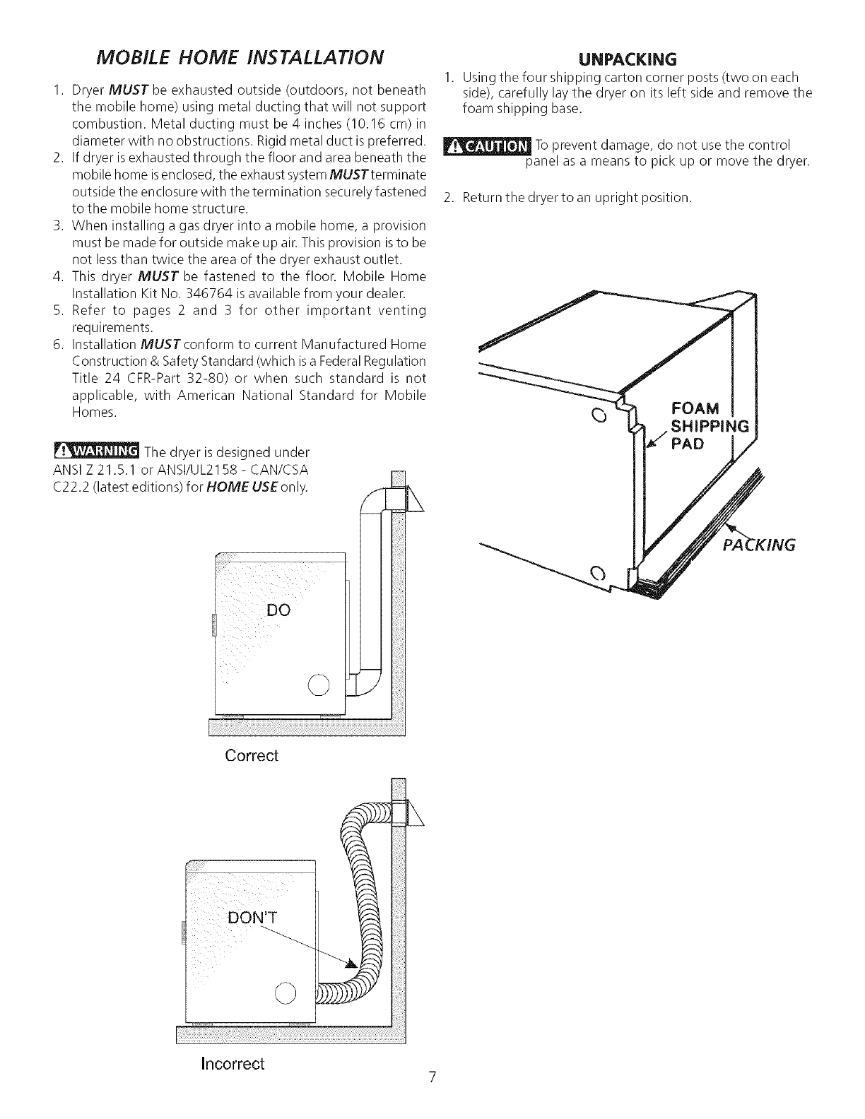
MOBILE HOME INSTALLATION
I. Dryer MUST be exhausted outside (outdoors, not beneath
the mobile home) using metal ducting that will not support
combustion. Metal ducting must be 4 inches (10.16 cm) in
diameter with no obstructions. Rigid metal duct is preferred.
2. If dryer is exhausted through the floor and area beneath the
mobile home isenclosed, the exhaust systemMUSTterminate
outside the enclosure with the termination securely fastened
to the mobile home structure.
3. When installing a gas dryer into a mobile home, a provision
must be made for outside make up air. This provision is to be
not lessthan twice the area of the dryer exhaust outlet.
4. This dryer MUST be fastened to the floor. Mobile Home
Installation Kit No. 346764 is available from your dealer.
5. Refer to pages 2 and 3 for other important venting
requirements.
6. Installation MUSTconform to current Manufactured Home
Construction & Safety Standard (which is a FederalRegulation
Title 24 CFR-Part 32-80) or when such standard is not
applicable, with American National Standard for Mobile
Homes.
The dryer is designed under
ANSI Z 21,5,1 or ANSI/UL2158- CAN/CSA
C22.2 (latest editions) for HOME USE only.
DO
UNPACKING
Using the four shipping carton corner posts (two on each
side), carefully lay the dryer on its left side and remove the
foam shipping base.
To prevent damage, do not use the control
panel as a means to pick up or move the dryer.
2. Return the dryer to an upright position.
_) FOAM
SHIPPING
PAD
Correct
i l ii
ill _ i
©!iii_iiiiiil
i_ii!iiii!i!i
Incorrect 7
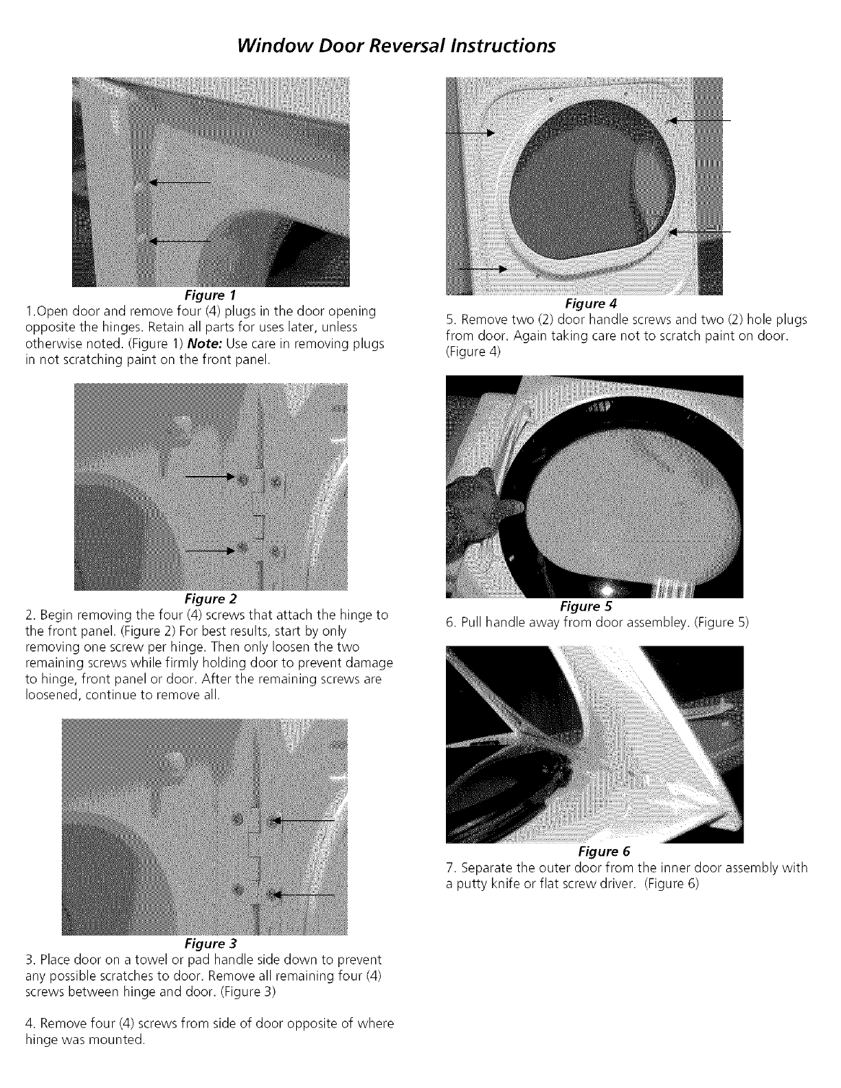
Figure 1
Window Door Reversal Instructions
1.0pen door and remove four (4) plugs in the door opening
opposite the hinges. Retain all parts for uses later, unless
otherwise noted. (Figure 1) Note: Use care in removing plugs
in not scratching paint on the front panel.
Figure 2
Figure 4
5. Remove two (2) door handle screws and two (2) hole plugs
from door. Again taking care not to scratch paint on door.
(Figure 4)
2. Begin removing the four (4) screws that attach the hinge to
the front panel. (Figure 2) For best results, start by only
removing one screw per hinge. Then only loosen the two
remaining screws while firmly holding door to prevent damage
to hinge, front panel or door. After the remaining screws are
loosened, continue to remove all.
Figure 3
Figure 5
6. Pull handle away from door assembley. (Figure 5)
Figure 6
7. Separate the outer door from the inner door assembly with
a putty knife or flat screw driver. (Figure 6)
3. Place door on a towel or pad handle side down to prevent
any possible scratches to door. Remove all remaining four (4)
screws between hinge and door. (Figure 3)
4. Remove four (4) screws from side of door opposite of where
hinge was mounted.
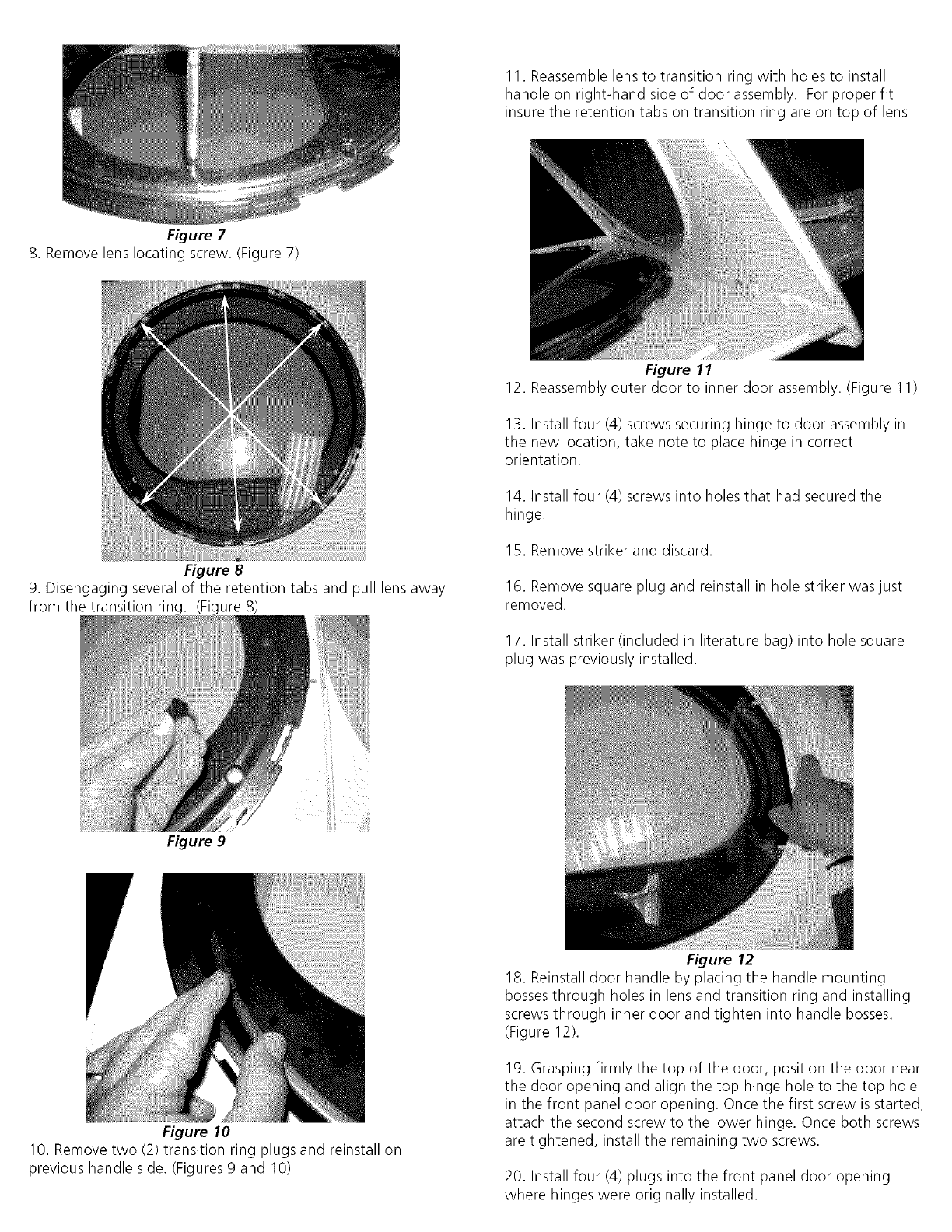
Figure 7
11. Reassemble lens to transition ring with holes to install
handle on right-hand side of door assembly. For proper fit
insure the retention tabs on transition ring are on top of lens
8. Remove lens locating screw. (Figure 7)
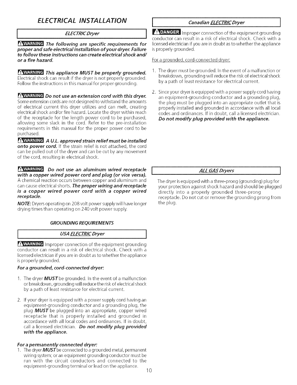
Figure 8
9. Disengaging several of the retention tabs and pull lens away
from the transition ring. (Figure 8)
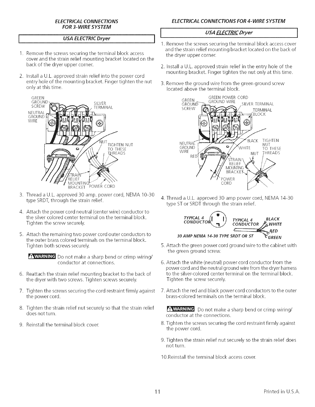
Figure 9
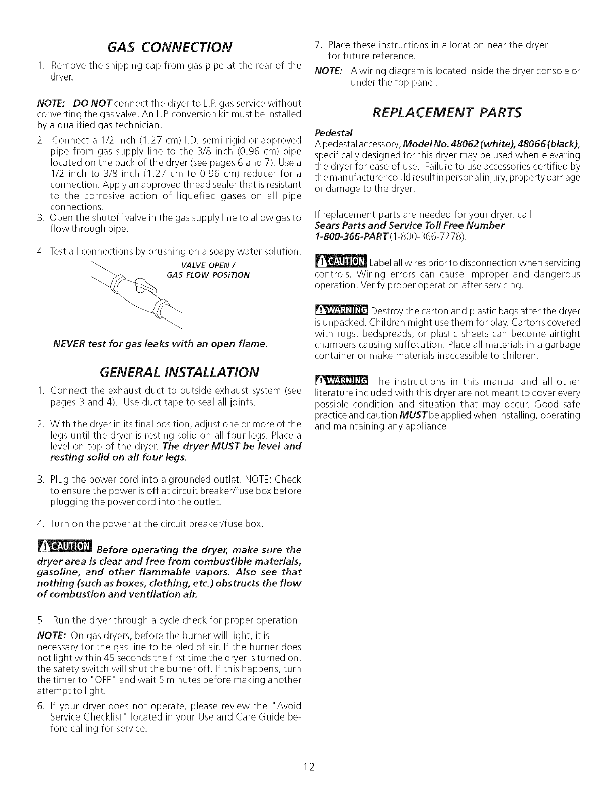
Figure 10
Figure 11
12. Reassembly outer door to inner door assembly. (Figure 11)
13. Install four (4) screws securing hinge to door assembly in
the new location, take note to place hinge in correct
orientation.
14. Install four (4) screws into holes that had secured the
hinge.
15. Remove striker and discard.
16. Remove square plug and reinstall in hole striker was just
removed.
17. Install striker (included in literature bag) into hole square
plug was previously installed.
10. Remove two (2) transition ring plugs and reinstall on
previous handle side. (Figures 9 and 10)
Figure 12
18. Reinstall door handle by placing the handle mounting
bosses through holes in lens and transition ring and installing
screws through inner door and tighten into handle bosses.
(Figure 12).
19. Grasping firmly the top of the door, position the door near
the door opening and align the top hinge hole to the top hole
in the front panel door opening. Once the first screw is started,
attach the second screw to the lower hinge. Once both screws
are tightened, install the remaining two screws.
20. Install four (4) plugs into the front panel door opening
where hinges were originally installed.
ELECTRICAL INSTALLATION
IELECTRICDryer
The following are specific requirements for
proper and safe electrical installation of your dryer. Failure
to follow these instructions can create electrical shock and/
or a fire hazard.
This appliance MUST be properly grounded.
Electrical shock can result if tile dryer is not properly grounded.
Follow the instructions in this manual for proper grounding.
Do not use an extension cord with this dryer.
Some extension cords are not designed to withstand the amounts
of electrical current this dryer utilizes and can melt, creating
electrical shock and/or fire hazard. Locate the dryer within reach
of the receptacle for the length power cord to be purchased,
allowing some slack in the cord. Refer to the pre-installation
requirements in this manual for the proper power cord to be
purchased.
A U.L. approvedstrain reliefmustbe installed
onto power cord. If tile strain relief is not attached, tile cord
can be pulled out of the dryer and can be cut by any movement
of the cord, resulting in electrical shock.
Do not use an aluminum wired receptacle
with a copper wired power cord and plug (or vice versa).
A chemical reaction occurs between copper and aluminum and
can cause electrical shorts. The proper wiring and receptacle
is a copper wired power cord with a copper wired
receptacle.
NOTE: Dryersoperating on 208 volt power supplywill have longer
drying times than operating on 240 volt power supply.
jCanadian ELECTR/CDryer J
_ Improper connection of tile equipment grounding
conductor can result in a risk of electrical shock. Check with a
licensedelectrician if you arein doubt as to whether the appliance
is properly grounded.
For a arounded, cord-connected dryer:
1. The dryer must be grounded. In the event of a malfunction or
breakdown, grounding will reduce the risk of electrical shock
by a path of least resistance for electrical current.
Since your dryer is equipped with a power supply cord having
an equipment-grounding conductor and a grounding plug,
the plug must be plugged into an appropriate outlet that is
properly installed and grounded in accordance with all local
codes and ordinances. If in doubt, call a licensed electrician.
Do not modify plug provided with the appliance.
ALL GAS Dryers
The dryer is equipped with a three-prong (grounding) plug for
your protection against shock hazard and should be plugged
directly into a properly grounded three-prong
receptacle. Do not cut or remove the grounding prong from
the plug.
GROUNDING REQUIREMENTS
USA ELECTR/CDryer i
Improper connection of the equipment grounding
conductor can result in a risk of electrical shock. Check with a
licensedelectrician if you are in doubt asto whether the appliance
is properly grounded.
For a grounded, cord-connected dryer:
I. Tile dryerMUSTbe grounded. In the event of a malfunction
or breakdown, grounding will reduce the risk of electrical shock
by a path of least resistance for electrical current.
2. If your dryer is equipped with a power supply cord having an
equipment-grounding conductor and a grounding plug, the
plug MUST be plugged into an appropriate, copper wired
receptacle that is properly installed and grounded in
accordance with all local codes and ordinances. If in doubt,
call a licensed electrician. Do not modify plug provided
with the appliance.
For a permanently connected dryer:
I. The dryerMUSTbe connected to a grounded metal, permanent
wiring system; or an equipment grounding conductor must be
run with the circuit conductors and connected to the
equipment-grounding terminal or lead on the appliance. 10
ELECTRICALCONNECTIONS ELECTRICALCONNECTIONS FOR 4- WIRE SYSTEM
FOR 3- WIRE SYSTEM
USA ELECTRICDryer
1. Remove the screws securing the terminal block access
cover and the strain relief mounting bracket located on the
back of the dryer upper corner.
2. Install a U.L approved strain relief into the power cord
entry hole of the mounting bracket. Finger tighten the nut
only at this time.
GREEN
SCREW
NEUTRAL
GROUND
WIRE
SILVER
TERMINAL
USA ELECTR/CDryer l
1. Remove the screws securing the terminal block accesscover
and the strain relief mounting bracket located on the back of
the dryer upper corner.
2. Install a U.L approved strain relief in the entry hole of the
mounting bracket. Finger tighten the nut only at this time.
3. Remove the ground wire from the green ground screw
located above the terminal block.
GREEN POWER CORD
GREEN SILVERTERMINAL
SCREW TERMINAL
BLOCK
tUTTIGHTEN NUT
TO THESE
_READS
BRACKET POWER CORD
3. Thread a U.L approved 30 amp. power cord, NEMA 10-30
type SRDT,through the strain relief.
4. Attach the power cord neutral (center wire) conductor to
the silver colored center terminal on the terminal block.
Tighten the screw securely.
5. Attach the remaining two power cord outer conductors to
the outer brasscolored terminals on the terminal block.
Tighten both screws securely.
Do not make a sharp bend or crimp wiring/
conductor at connections.
6. Reattach the strain relief mounting bracket to the back of
the dryer with two screws. Tighten screws securely.
7. Tighten the screws securing the cord restraint firmly against
the power cord.
8. Tighten the strain relief nut securely so that the strain relief
does not turn.
9. Reinstall the terminal block cover.
TIGHTEN
NUT
GROUND WHITE TO THESE
WIRE NUT -HREADS
STRAIN
RELIEF
BRACKET,.
POWER
CORD
4. Thread a U.L approved 30 amp power cord, NEMA 14-30
type ST or SRDTthrough the strain relief.
.
TYPICAL 4 TYPICAL 4 BLACK
C_WHITE
_,_I_ED
30 AMP NEMA 14-30 TYPE SRDT OR ST _GREEN
Attach the green power cord ground wire to the cabinet with
the green ground screw.
.Attach the white (neutral) power cord conductor from the
power cord and the neutral ground wire from the dryer harness
to the silver-colored center terminal on the terminal block.
Tighten the screw securely.
7. Attach the red and black power cord conductors to the outer
brass-colored terminals on the terminal block.
.
Do not make a sharp bend or crimp wiring/
conductor at the connections.
Tighten the screws securing the cord restraint firmly against
the power cord.
9. Tighten the strain relief nut securely so the strain relief does
not turn.
10.Reinstall the terminal block accesscover.
11 Printed in U.S.A.
GAS CONNECTION
1. Remove the shipping cap from gas pipe at the rear of the
dryer.
NOTE: DO NOTconnect the dryer to L.R gas service without
corwerting the gas valve. An LR conversion kit must be installed
by a qualified gas technician.
2. Connect a I/2 inch (1.27 cm) I.D. semi-rigid or approved
pipe from gas supply line to the 3/8 inch (0.96 cm) pipe
located on the back of the dryer (see pages 6 and 7). Usea
1/2 inch to 3/8 inch (1.27 cm to 0.96 cm) reducer for a
connection. Apply an approved thread sealer that is resistant
to the corrosive action of liquefied gases on all pipe
connections.
3. Open the shutoff valve in the gas supply line to allow gas to
flowthrough pipe.
4. Testall connections by brushing on a soapy water solution.
VALVE OPEN I
GAS FLOW POSITION
NEVER test for gas leaks with an open flame.
GENERAL INSTALLATION
I. Connect the exhaust duct to outside exhaust system (see
pages 3 and 4). Use duct tape to seal all joints.
2. With the dryer in its final position, adjust one or more of the
legs until the dryer is resting solid on all four legs. Place a
level on top of the dryer. The dryer MUST be level and
resting solid on all four legs.
3. Plug the power cord into a grounded outlet. NOTE: Check
to ensure the power is off at circuit breakedfuse box before
plugging the power cord into the outlet.
4. Turn on the power at the circuit breaker/fuse box.
Before operating the dryer, make sure the
dryer area is clear and free from combustible materials,
gasoline, and other flammable vapors. Also see that
nothing (such as boxes, clothing, etc.) obstructs the flow
of combustion and ventilation air.
7. Place these instructions in a location near the dryer
for future reference.
NOTE: Awiring diagram is located inside the dryer console or
under the top panel.
REPLACEMENT PARTS
Pedestal
A pedestal accessory,ModelNo. 48062 (white), 48066(black),
specifically designed for this dryer may be used when elevating
the dryer for ease of use. Failure to use accessories certified by
the manufacturer could result in personal injury, property damage
or damage to the dryer.
If replacement parts are needed for your dryer, call
Sears Parts and Service Toll Free Number
1-800-366-PART(1-800-366-7278).
Labelall wires prior to disconnection when servicing
controls. Wiring errors can cause improper and dangerous
operation. Verify proper operation after servicing.
Destroy the carton and plastic bags after the dryer
is unpacked. Children might use them for play. Cartons covered
with rugs, bedspreads, or plastic sheets can become airtight
chambers causing suffocation. Place all materials in a garbage
container or make materials inaccessible to children.
The instructions in this manual and all other
literature included with this dryer are not meant to cover every
possible condition and situation that may occur. Good safe
practice and caution MUSTbe applied when installing, operating
and maintaining any appliance.
5. Run the dryer through a cycle check for proper operation.
NOTE: On gas dryers, before the burner will light, it is
necessary for the gas line to be bled of air. If the burner does
not light within 45 seconds the first time the dryer is turned on,
the safety switch will shut the burner off. If this happens, turn
the timer to "OFF" and wait 5 minutes before making another
attempt to light.
6. If your dryer does not operate, please review the "Avoid
Service Checklist" located in your Use and Care Guide be-
fore calling for service.
12
Tabla de Materias
Requerimientos de instalaciOn preliminares ....................................................................................................................... 13
Requerimientos el_ctricos ............................................................................................................................................... 13
Requerimientos del sistema de escape......................................................................................................................... 14-16
Requerimientos del suministro de gas.............................................................................................................................. 16
Ubicaci6n de su secadora .............................................................................................................................................. 16
Dimensiones para la instalaciOn ..................................................................................................................................... 17
Instalaci6n en casas m6viles .......................................................................................................................................... 18
Desembalaje ............................................................................................................................................................... 18
Puerta reversible ........................................................................................................................................................ 19-20
Instalaci6n el_ctrica ..................................................................................................................................................... 21
Requerimientos para la puesta a tierra .............................................................................................................................. 21
ConexiOnes el_ctricas - trifilares ..................................................................................................................................... 22
ConexiOnes el_ctricas - tetrafilares .................................................................................................................................. 22
InstalaciOn ................................................................................................................................................................... 23
Piezas de recambio ....................................................................................................................................................... 23
SEGURIDAD de SECADORA
Antes de comenzar la instalaci6n, lea cuidadosamente estas instrucciones. Esto simplificara la instalaci6n y asegurara
que la secadora se instale correctamente y de manera segura. Despues de completar la instalaci6n, coloque estas
instrucciones cerca de la secadora para referencia futura.
NOTA: La alimentaci6n electrica para la secadora debera cumplir con los c6digos y reglamentos locales y con la Oltima
edici6n del C6digo El_ctrico Nacional, ANSI/NFPA 70 o en Canada CSA C22.1 C6digo El_ctrico Canadiense, Parte 1.
NO TA:La alimentaci6n de gas para la secadora debera cumplir con los c6digos y reglamentos Iocales y con la Oltima edici6n
del C6digo Nacional para Gases Combustibles, ANSI Z223.1 o en Canada CAN/CGA B 149.12.
NO TA: La secadora esta clasificada para USO DOMESTICO solamente, de acuerdo con la norma ANSI Z21.5.1 o ANSI/UL
2158 -CAN/CSA C22.2 No. 112 (las Oltimas edici6nes). Esta secadora no se recomienda para uso commercial tal como en
restaurantes, salones de belleza, etc.
Su seguridad y la seguridad de terceros son muy importantes.
Hemos proporcionado muchos mensajes importantes para la seguridad en las Instrucciones de OperaciOn
del Manual de Uso y Mantenimiento, las Instrucciones de InstalaciOn y en el mismo aparato. Siempre lea
y obedezca todos los mensajes para seguridad.
_Este simbolo significa alerta. Este simbolo Io alerta acerca de peligros que pueden matar o lesionar,
tanto a usted como a otras personas. Todos los mensajes de seguridad set,in precedidos por el simbolo
de alerta para su seguridad y la palabra "PELIGRO o ADVERTENCIA" (DANGER"o WARNING). Estas
palabras significan:
PELIGRO (DANGER) Usted morir_ oresultar_ seriamente lesionado si no sigue las
instrucciones siguientes.
ADVERTENCIA (WARNING) Usted puede morir o resultar seriamente lesionado
si no sigue las instrucdones siguientes.
Todos los mensajes de seguridad identificar_n el peligro, le dir2n a usted c6mo reducir la
posibilidad de lesi6n y tambi_n qu_ puede suceder si no se siguen las instrucciones.
Parasu seguridad, siga las instrucciones contenidas en este manual afin de reducir a un minimo los riesgos de
incendio o explosion o para evitar daAos materiales, lesiones personales o la muerte.
No almacene ni utilice gasolina u otros vapores y liquidos inflamables en la proximidad de _ste o de cualquier otro artefacto
el_ctrico.
QUE DEBE HACER SI PERCIBEOLOR A GAS
No trate de encender ningOn artefacto el_ctrico.
. Notoque ningOn interruptor el_ctrico; no use ningOn tel_fono en suedificio.
. Haga salir atodos los ocupantes de la habitation, del edificio y del lugar.
Llame a su proveedor de gas desde el tel_fono de un vecino. Siga las instrucciones del proveedor de gas.
o Si no Iogra comunicarse con su proveedor de gas, Ilame al departamento de bomberos.
Lainstalaci6n y el servicio de mantenimiento debe de realizarlos un instalador calificado, la agencia de servicios o el proveedor de
gas.
13
REQUERIMIENTOS DE INS TALA CION
PRELIMINARES
Herramientas y materiales necesarios para la instalaci6n:
1. Destornillador Phillips
2. Pinzasuniversales
3. Nivel de gota
4. Destornillador para tornillo de cabeza plana o recta
5. Cinta para ductos
6. Ducto metalico rigido o flexible de 4" (10,2 cm)
7. Caperuza de salida
8. Sellador de tuberias (gas)
9. Un cuchillo de plastico
[REQUERIMIENTOS ELECTRICOS
Secadoras ELECTR/CAS i
CIRCUITO - Circuito derivado individual de 30 amperios, con
fusibles de 30 amp. del tipo de retardo o disyuntores.
Use circuitos separados con un interruptor o fusible para las
lavadoras y las secadoras y no haga funcionar la lavadora y
secadora en el mismo circuito.
ALIMENTACIONELECTRICA - Corriente aIterna, monofasica,
60 Hz, 240 voltios; trifilar o tetrafilar.
KIT DE CABLE TOMACORRIENTE - La secadora se DEBE usar
un cable tomacorriente trifilar NEMA 10-30 tipo SRDTpara un
voltaje nominal minimo de 240 voltios CA, 30 amp, con 3
conectores de horquillas con terminales abiertos y extremos
dirigidos hacia arriba o conectores de anillo cerrado y marcados
para uso en secadoras de ropa.
AVERTISSEMENT-Risquedechocelectrique. Un appareil mis
a laterre a I'aide d'un lien ou cable conducteur neutre. Laraise a
laterre aI'aide d'un conducteur ou cable neutre est interdite dans
les cassuivants : (1)les installations de nouveau circuit d_vir_ (2)
les maisons mobiles (3)les v_hicules r_cr6atifs ou caravanes et (4)
les r_gions oQlescodes Iocaux interdisent la raisea laterre a I'aide
d'un c_ble ou conducteur neutre. (1) D_branchez le conducteur
ou c_ble du neutre, (2) utilisez la borne de raise a la terre ou le
c_ble de raise a la terre de I'appareil conform_ment aux codes
Iocaux et (3) connectez ou branchez la borne neutre ou le c_ble
au neutre du circuit d_vire de la mani_re habituelle (si I'appareil
doit 6tre connecte a I'aided'un cordon, utilisez un cordon a4 c_bles
ou ills pour ce faire). N'UTILISEZQUE DESCABLESOU FILSEN
CUIVRE. SeDEBEutilizarun cord6n el_ctricotetrafilar NEMA 14-
30 tipo $RDTo ST(como sea necesario) para un voltaje nominal
minimo de 240 voltios CA, 30 amp con 4 conectores de horquillas
con terminales abiertos y extremos dirigidos hacia arriba o
conectores de anillo cerrado y marcados para uso en secadoras
de ropa. Ver CONEXIONES ELECTRICAS PARA SISTEMAS
TETRAFILARES.
(Canada - un cord6n de suministro de energia de 4 alambres es
instalado en la secadora.)
TOMACORRIENTE- Eltomacorriente NEMA 10-30R debe estar
ubicado de manera que el cable tomacorriente Ilegue hasta 61
cuando la secadora est_ instalada. (Canada - receptaculo NEMA
14-30R.)
I Secadora.,FaGAS 1
CIRCUITO- Circuito individual derivado de 15 amp, con fusibles
de 15 amp. de retardo maximo o disyuntor.
ALIMENTACION EL_'CTRICA- Corriente alterna, monofasica,
60 Hz, 120 voltios, trifilar.
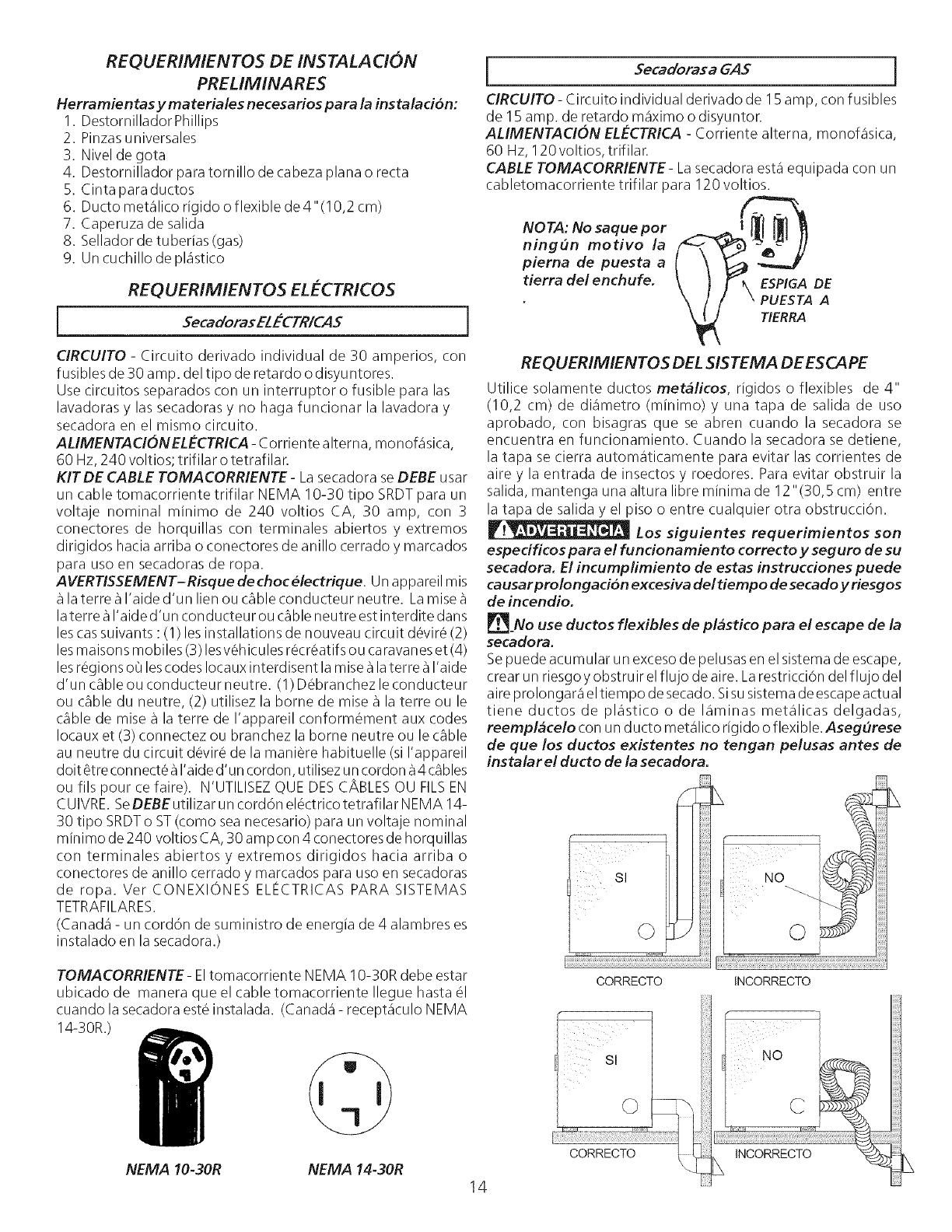
CABLE TOMACORRIENTE- Lasecadora esta equipada con un
cabletomacorriente trifilar para 120 voltios.
NOTA: No saque per
ningun motivo la
pierna de puesta a
tierra del enchufe. ESPIGA DE
PUESTA A
TERRA
REQUERIMIENTOS DEL SISTEMA DE ESCAPE
Utilice solamente ductos met&licos, rigidos o flexibles de 4"
(10,2 cm) de diametro (minimo) y una tapa de salida de uso
aprobado, con bisagras que se abren cuando la secadora se
encuentra en funcionamiento. Cuando la secadora se detiene,
la tapa se cierra automaticamente para evitar las corrientes de
aire y la entrada de insectos y roedores. Para evitar obstruir la
salida, mantenga una altura libre minima de 12"(30,5 cm) entre
la tapa de salida y el piso o entre cualquier otra obstrucciOn.
Los siguientes requerimientos son
especificos para el funcionamiento correcto y seguro de su
secadora. El incumplimiento de estas instrucciones puede
causar prolongaci6n excesiva del tiempo de secado y riesgos
de incendio.
O_No use ductos flexibles de plastico para el escape de la
secadora.
Sepuede acumular un exceso de pelusas en el sistema de escape,
crear un riesgo y obstruir elflujo de aire. Larestricci6n del flujo del
aire prolongara el tiempo de secado. Sisu sistemade escapeactual
tiene ductos de plastico o de laminas metalicas delgadas,
reempl&celo con un ducto metalico rigido o flexible. Asegurese
de que los ductos existentes no tengan pelusas antes de
instalar el ducto de la secadora.
81
0
CORRECTO
1
¸¸¸¸¸¸¸¸¸¸¸¸¸¸¸¸¸¸No
I
i:i;i!i_i_I_i'i_ii_ii:iz_iiii_iii_i;ii_i_ii_i!ii:i__i_i,i_i_i;ii_!_,i_ii_ii_!ii_ii_i!i'i_i_i_i_,ii_!_!i!_i_ii__;!i_i_i_!!!_i_i_i_i_i_i!i_i_i!i_i_!_i_ii_i!i_l_i_liiz!_l_i_lil_!l_il_l_i_l_i_l_i_l_i_l_i_l_i_l_i_l_i_l_i_l_i_l_i_l_i_l_i_l_!i_ili_!_i_i_i_
INCORRECTO
NEMA 10-30R NEMA 14-30R
14
Risque d'incendie- Une sOcheuse_ linge produit de lacharpie
combustible. Si el escape de la secadora no se dirige al exterior,
alqunas pelusas finas seran sopladas hacia el recinto donde se
efect0a el lavado. La acumulaciOn de pelusas en cualquier lugar
de la casa, puede crear un peligro para la salud y un riesgo de
incendio. La secheuse dolt @tre connectee _une bouche
d'e vacuation vers I'ext_rieur du b&timent ou de I'immeuble.
Vousdevezinspecter rOgu%rement I'event extOrieuret enlevertoute
accumulation de charpie autour de 1'Oventet dans la cavit6 du
conduit d'Ovacuation.
No permita que los materiales combustibles (por ejemplo:
la ropa, cortinas/cortinajes, papel) tengan contacto con los
ductos. Elescapede lasecadoraNODEBEdirigirse hacia el interior
de una chimenea, hacia una pared, hacia el cielo raso o hacia
cualquier otro espacio reducido del edificio, donde puede ocurrir
acumulaciOn de pelusasy constituir un peligro de incendio.
Exceder la Iongitud del conducto rigido o los numeros
de codos permitidos en los diagramas "LARGO MAXIMO"
puede disminuir lacapacidad de dedesahogo del sistema. Obstruir
el conducto puede provocar peligro de incendio, asi como
aumentar eltiempo de secado.
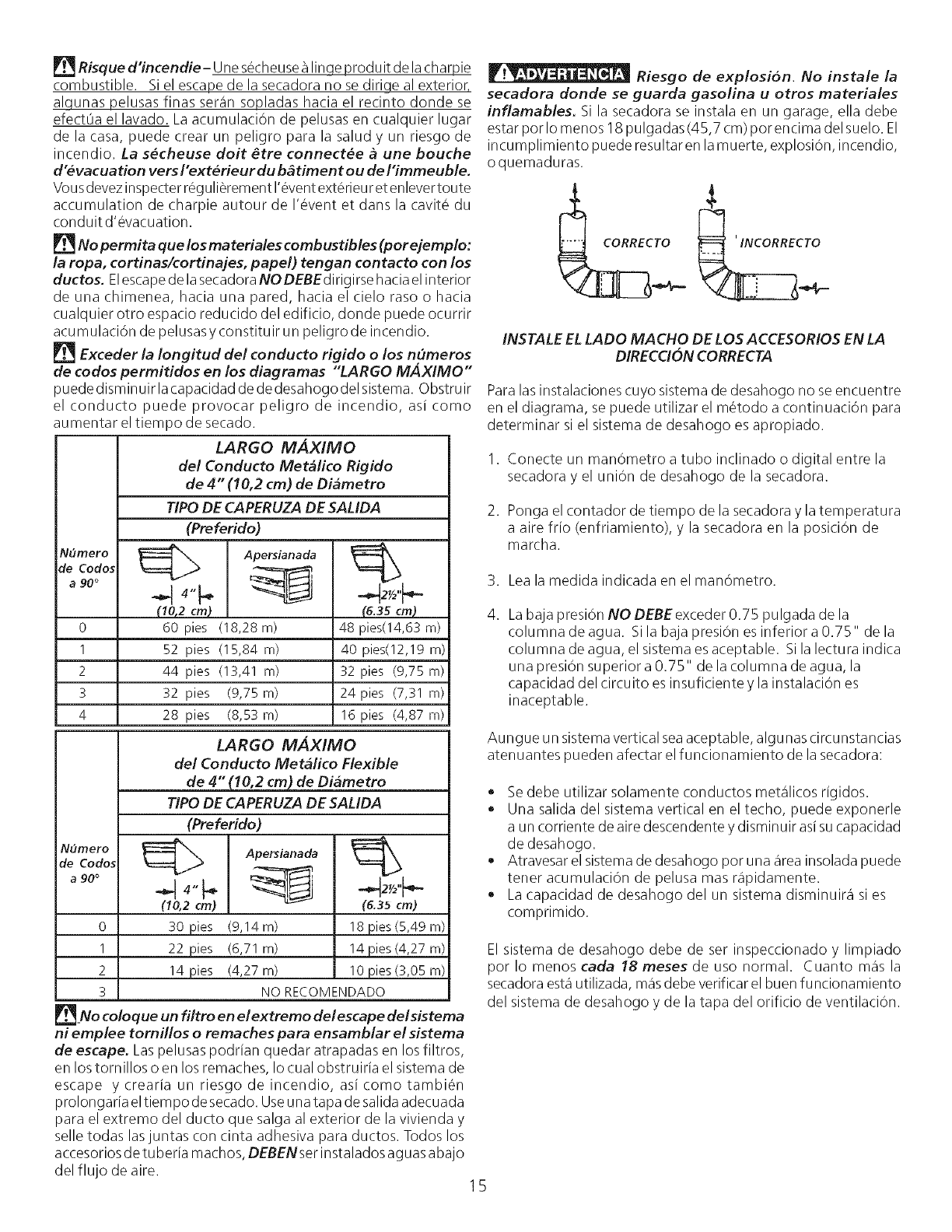
LARGO MAXIMO
del Conducto Metalico Rigido
de 4" (10,2 cm) de Diametro
TIPODE CAPERUZA DE SALIDA
(Preferido)
(10,2 cm_ (6.35 cm_
0 60 pies (18,28 m) 48 pies(14,63 m)
1 52 pies (15,84 m) 40 pies(12,19 m)
2 44 pies (13,41 m) 32 pies (9,75 m)
3 32 pies (9,75 m) 24 pies (7,31 m)
4 28 pies (8,53 m) 16 pies (4,87 m)
LARGO MAXIMO
del Conducto Metalico Flexible
de 4" (10,2 cm) de Diametro
TIPO DE CAPERUZA DE SALIDA
(Preferido)
NOmerO_a90°_4"_,_ Apersianada_2Y2_'-
de Codos
,,
0 30 pies (9,14m) 18 pies (5,49 m)
1 22 pies (6,71 m) 14 pies (4,27 m)
2 14 pies (4,27 m) 10 pies (3,05 m)
3NO RECOMENDADO
__No coloq ue un filtro en el extremo del escape del sistema
ni emplee tornillos oremaches para ensamblar el sistema
de escape. Laspelusas podrian quedar atrapadas en los filtros,
en los tornillos o en los remaches, Io cual obstruiria el sistema de
escape ycrearia un riesgodeincendio, asicomotambi_n
prolongaria eltiem po desecado. Useunatapa de salida adecuada
para el extremo del ducto que salga al exterior de la vivienda y
selle todas las juntas con cinta adhesiva para ductos. Todos los
accesoriosde tuberia machos, DEBENserinstalados aguas abajo
del flujo de aire.
Riesgo de explosion. No instale la
secadora donde se guarda gasolina u otros materiales
inflamables. Si la secadora se instala en un garage, ella debe
estar por Io menos 18 pulgadas (45,7 cm) por encima del suelo. El
incumplimiento puede resultar en lamuerte, explosion, incendio,
oquemaduras.
CORRECTO
INSTALE ELLADO MACHO DE LOS ACCESORIOS EN LA
DIRECCION CORRECTA
Paralas instalaciones cuyo sistema de desahogo no se encuentre
en el diagrama, se puede utilizar el metodo a continuaciOn para
determinar si el sistema de desahogo es apropiado.
1. Conecte un manOmetro a tubo inclinado o digital entre la
secadora y el union de desahogo de la secadora.
2. Ponga el contador de tiempo de la secadora y la temperatura
a aire frio (enfriamiento), y la secadora en la posiciOn de
marcha.
3. Leala medida indicada en el manOmetro.
.Labaja presi6n NO DEBE exceder 0.75 pulgada de la
columna deagua. Sila baja presi6n es inferior a 0.75" de la
columna de agua, el sistema es aceptable. Sila lectura indica
una presi6n superior a 0.75" de la columna de agua, la
capacidad del circuito es insuficiente y la instalaci6n es
inaceptable.
Aungue un sistemavertical seaaceptable, algunas circunstancias
atenuantes pueden afectar el funcionamiento de la secadora:
Sedebe utilizar solamente conductos metalicos rigidos.
Una salida del sistema vertical en el techo, puede exponerle
a un corriente de aire descendente y disminuir asi su capacidad
de desahogo.
Atravesar el sistemade desahogo por una area insolada puede
tener acumulaci6n de pelusa mas r@idamente.
La capacidad de desahogo del un sistema disminuira si es
comprimido.
El sistema de desahogo debe de ser inspeccionado y limpiado
por Io menos cada 18 meses de uso normal. Cuanto mas la
secadoraesta utilizada, masdebe verificar el buen funcionamiento
del sistema de desahogo y de la tapa del orificio de ventilaciOn.
15
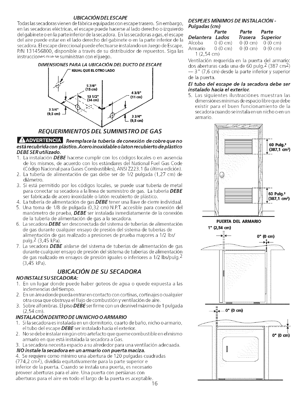
UBICACION DEL ESCAPE
Todaslas secadorasvienen defabrica equipadas con escapetrasero. Sinembargo,
en las secadoras elOctricas, el escape puede hacerse al lado derecho o izquierdo
del gabinete o en la parte inferior de la secadora. Enlassecadoras agas,el escape
del aire puede estar en el lado derecho del gabinete o en la parte inferior de la
secadora. Elescapedirectional puede efectuarse instalando unJuego de Escape,
P/N 131456800, disponible a traves de su distribuidor de repuestos. Siga las
instruccion_ r_J__esuministran con eljuego.
DIMENSIONES PARA LA UBICACION DEL DUCTO DE ESCAPE
LS I
€34ore) J m
)
"_ /L(9,5 crn)
REQUERIMIENTOS DEL SUMINISTRO DE GAS
Reernplace /a tuberia de conexion de cobre que no
esta recubrida con plastico. Acero inoxidable o laton recu bierto de plastico
DEBE SERutilizado.
I. La instalaci0n DEBE hacerse cumplir con los cOdigos locales o en ausencia
de los mismos, de acuerdo con los estandares del National Fuel Gas Code
(COdigo National para GasesCombustibles), ANSIZ223.1 (la 01timaediciOn).
2. La tuberia de alimentaciOn de gas debe ser de 1/2 pulgada (1,27 cm) de
diametro.
3. Si esta permitido por los cOdigos locales, se puede usar tuberia de metal
para conectar su secadora a la Iinea de suministro de gas. Latuberia DEBE
ser fabricada de acero inoxidable o latOn recubierto de plastico.
4. Latuberia de alimentaciOn de gas DEBE tener una Ilave de cierre individual.
5. Una toma de I/8 de pulgada (0,32 cm) N.RT. accesible para conexi0n del
manOmetro de prueba, DEBE ser instalada inmediatamente de la conexi0n
de la tuberia de alimentaci0n de gas a la secadora.
6. La secadora DEBE ser desconectada del sistema de tuberias de alimentaci0n
de gas durante cualquier ensayo de presiOn del sistema de tuberias de
alimentaciOn de gas realizado a presiones de prueba mayores a 1/2 Ibs/
pulg2 (3,45 kPa).
7. La secadora DEBE aislarse del sistema de tuberias de alimentaci0n de gas
durante cualquier ensayo de presi0n del sistema de tuberias de alimentaci0n
de gas realizado en ensayos de presiOn iguales o inferiores a 1/2 Ibs/pulg. 2
(3,45 kPa).
UBICA CION DE SU SECADORA
NO INSTALESU SECADORA:
1. En un lugar donde puede haber goteos de agua o quede expuesta a las
inclemencias del tiempo.
2. Enun areadonde pueda entrar en contacto con cortinas, cortinajes o cualquier
otra cosaque obstruya el flujo de combustion y ventilaciOn de aire.
3. Sobre alfombras. Elpiso DEBEserfirme con un desnivel maximo de I pulgada
(2,54 cm).
INSTALACION DENTRO DE UN NICHO OARMARIO
1. Sila secadora es instalada en un dormitorio, cuarto de baho, nicho o armario,
el tubo del escapeDEBE ser instalado hacia el exterior.
2. No sedebe instalar ning0n otro artefacto que queme combustible en el mismo
armario en que esta instalada la secadora a Gas.
3. Lasecadora necesita espacio asu alrededor para una ventilaciOn adecuada.
NO instale la secadora erl tit} armario con puerta maciza.
4. Se requiere corno minimo una abertura de 120 pulgadas cuadradas
(774,2 cm2), dividida equitativamente para la parte superior e
inferior de la puerta. Cuando se instala una puerta, es necesario
proveer aberturas para el aire. Una puerta con persianas con
aberturas para el aire en todo el largo de la puerta es aceptable.16
DESPEJESMiNIMOS DE INSTALACION -
Pulgadas (cm)
Parte Parte Parte
De/antera Lados Trasera Superior
Alcoba 0 (0 cm) 0 (0 cm) 0 (0 cm)
Armario 0 (0 cm) 0 (0 cm) 0 (0 cm)
I (2,54 cm)
Ventilaci0n requerida en la puerta del armario:
dos aberturas cada una de 60 pulg2 (387 cm2)
-- 3" (7,6 cm) desde la parte inferior y superior
de la puerta.
El tubo del escape de la secadora debe ser
instalado hacia el exterior.
5. Las siguientes ilustraci0nes muestran las
dimensiOnesminimas deespacio libreque debe
existir para el buen funcionamiento de la
secadora cuando seinstala en un nicho o en un
armario.
PUERTA DEL ARMARIO
1" (2,54crnl
II
"O"(0 crnl
II ii
II _"lN
H
_,,i_o" (ocm)
ii
JJ
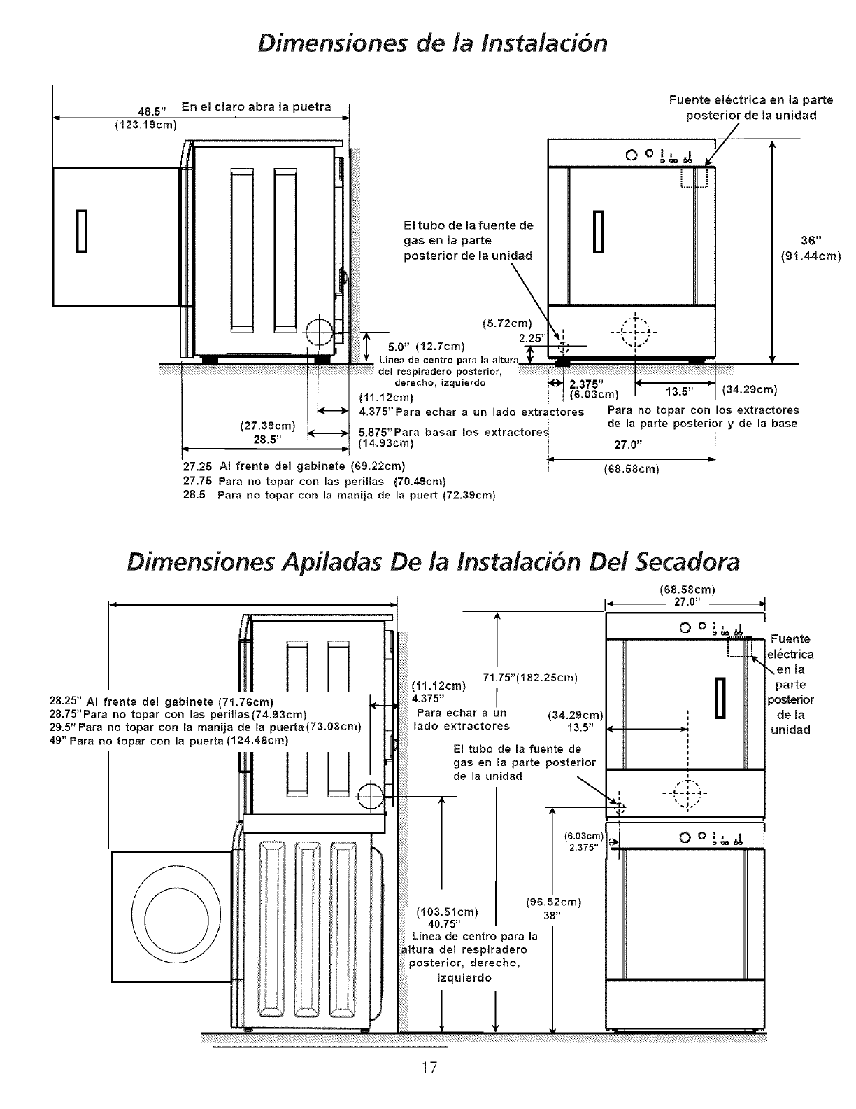
Dimensiones de la instalaaY)n
l
48,5"
(123.19cm'
En el claro abra la puetra
(27.39cm)
28.5"
27.25 AI frente del gabinete (69.22cm)
27.75 Para no topar con las perillas (70.49cm)
28.5 Pare no topar con la manija de la puert (72.39cm)
El tubo de la fuente de
gas en la parte
posterior de la unidad
-$---
5.0" (12.7cm)
Linea de eentro para la alture _If
del respiradero posterior, _:_i
derecho, izquierdo
(11.12cm)
4.375"Pare echar aun lado extractores
5.875"Para baser los extractore_
t
(14.93cm)
l
Fuente ei_ctrica en la parte
posterior de la unidad
/.
0 o _,'_ g
[...i
--i--'-_-
36"
(91.44cm)
Para no topar con los e×tractores
de la parte posterior y de la base
27.0"
(68.58cm)
Dimensiones Apiladas De la Instalaci6n De! Secadora
28.25" A! frente del gabinete (71.76cm)
28.75"Pare no topar con las perillas(74.93cm)
29.5" Pare no toper con la manija de la puerta (73.03cm)
49" Para no toper con la puerta (124.46cm) IIII
(11.12cm)
4.375"
Para echar a un
lado extractores
T
71.75"(182.25cm)
I(34.29cm)
13.5"
El tubo de la fuente de
gas en la parte posterior
de la unidad _.
A(6.03cm)
2.375"
(96.52cm)
(103.51cm) 38"
40.75"
Linea de centro para la
Itura del respiradero
posterior, derecho,
izquierdo
(68.58cm)
_- 27.0"
Fuente
el_ctrica
,.en la
parte
)osterior
de la
unidad
17
INSTALAC!ON EN CASAS MOVILES
1. Eltubo de escape de la secadora DEBE ser instalado
hacia el exterior (Elescape debe colocarse en la parte
exterior y no debajo de la casa mOvil.) Debe usarse
ducto de metal que no sea combustible. Elducto de
metal debe tener cuatro pulgadas (10,16 cm) de
diametro y no tener obstrucciones. Espreferible usar
ducto de metal que sea rigido.
2. Si el tubo de escape de la secadora corre a trav6s del
piso y el area debajo de la casa mOvil esta cerrada, el
ducto de escapeDEBE terminar fuera del recinto, con
el extremo final asegurado en contra de la estructura
de la casa mOvil.
3. AI instalar una secadora de gas en una casa mOvil,
hay que instalar una provision de aire fresco
suplementario. Laprovisi6n tiene que ser masgrande
que dos veces el espacio del escape de la secadora.
4. Estasecadora DEBE asegurarse al piso. Eljuego para
instalaciOn en la casa mOvil es el No. 346764 y Io
puede adquirir con su distribuidor.
5. Vea las paginas 2 y 3 para otros requisitos importantes
de ventilaciOn.
6. La instalaciOn DEBE cumplir con las estandares
aplicables de la Manufactured Home Construction &
Safety Standard - Estandares de Seguridad y
ConstrucciOn de Casas Prefabricadas (Titulo 24 CFR-
Parte 32-80 del Reglamento Federal) o cuando dichos
estandares no sean aplicables, se deben complir con
los estandares de la American National Standard for
Mobile Homes (Estandares Nacionales Americanas
para Viviendas M6viles).
w_
r_ Esta secadora ha sido disehada
PARA USO DOMESTICO solamente, de acuerdo con la
norma ANSI Z 21.5.1 o ANSI/UL 2158-CAN/CSA C22.2
(las 01timas ediciones).
MODEL OS A UTONOMOS CON CONSOLA
SUPERIOR DIMENSIONES PARA LA INSTALAC!ON
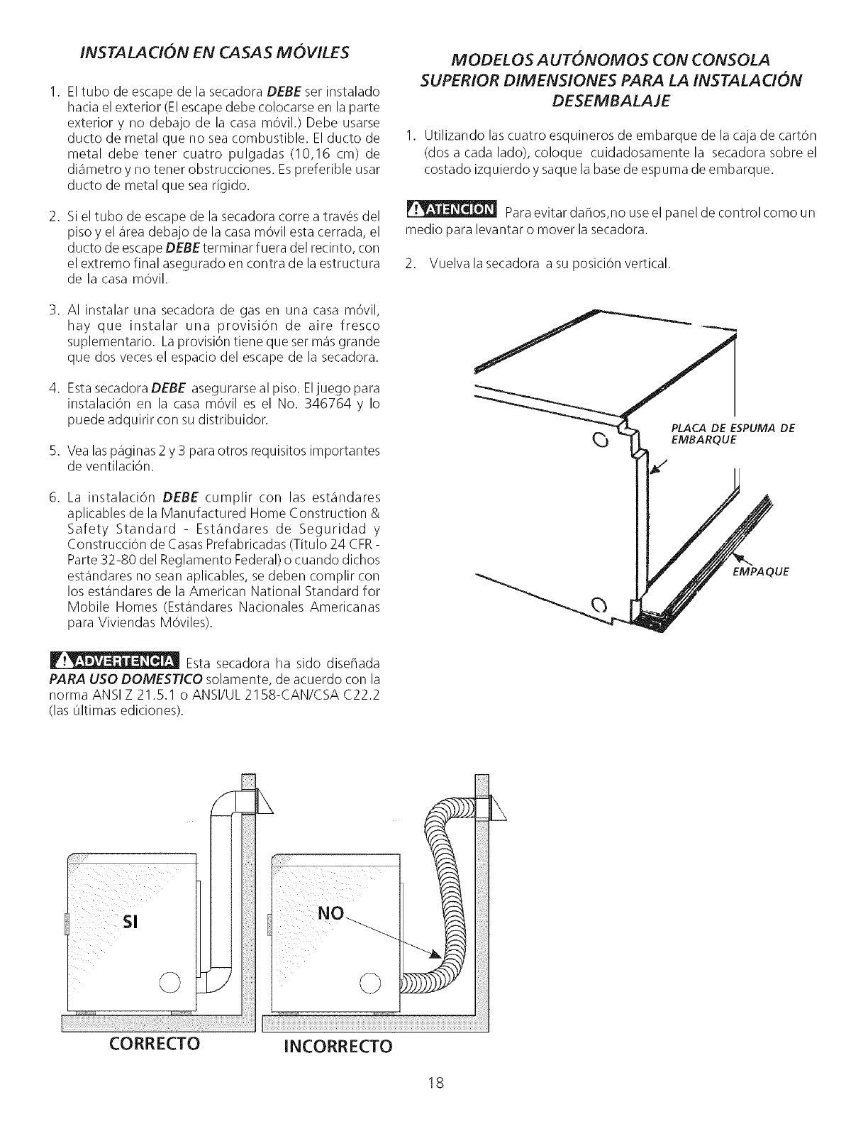
DESEMBALAJE
I. Utilizando las cuatro esquineros de embarque de la caja de cart6n
(dos a cada lado), coloque cuidadosamente la secadora sobre el
costado izquierdo y saque la base de espuma de embarque.
Paraevitar dahos,no use el panel de control como un
medio para levantar o mover la secadora.
2. Vuelva la secadora a su posiciOn vertical.
PLACA DE ESPUMA DE
EMBARQUE
EMPAQUE
Sl
©
CORRECTO INCORRECTO
18
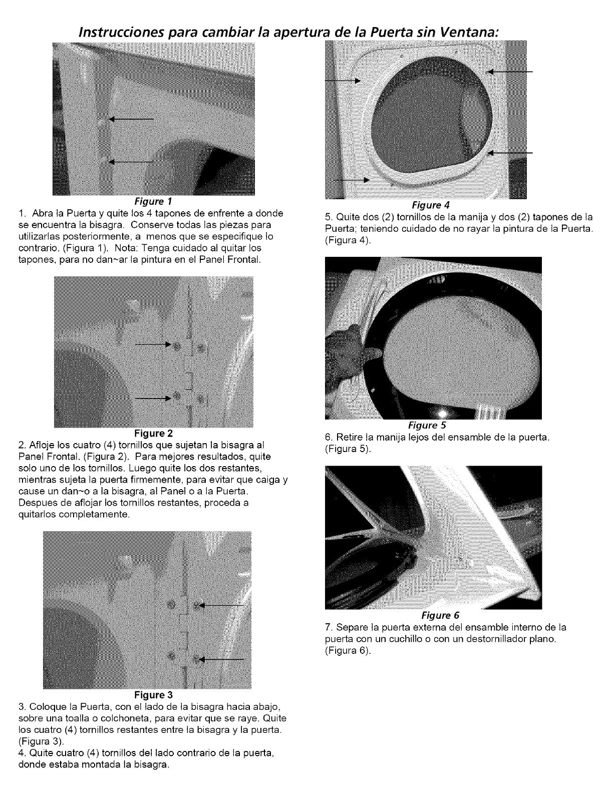
Instrucciones para carnbiar la apertura de la Puerta sin Ventana:
Figure 1
1. Abra la Puerta y quite los 4 tapones de enfrente a donde
se encuentra la bisagra. Conserve todas las piezas para
utilizarlas posteriormente, a menos que se especifique Io
contrario. (Figura 1). Nota: Tenga cuidado al quitar los
tapones, para no dan~ar la pintura en el Panel Frontal.
Figure 2
Figure 4
5. Quite dos (2) tornillos de la manija y dos (2) tapones de la
Puerta; teniendo cuidado de no rayar la pintura de la Puerta.
(Figura 4).
2. Afloje los cuatro (4) tornillos que sujetan la bisagra al
Panel Frontal. (Figura 2). Para mejores resultados, quite
solo uno de los tornillos. Luego quite los dos restantes,
mientras sujeta la puerta firmemente, para evitar que caiga y
cause un dan~o a la bisagra, al Panel o a la Puerta.
Despues de aflojar los tornillos restantes, proceda a
quitarlos completamente.
Figure 3
Figure 5
6. Retire la manija lejos del ensamble de la puerta.
(Figura 5).
Figure 6
7. Separe la puerta externa del ensamble interno de la
puerta con un cuchillo o con un destornillador piano.
(Figura 6).
3. Coloque la Puerta, con el lado de la bisagra hacia abajo,
sobre una toalla o colchoneta, para evitar que se raye. Quite
los cuatro (4) tornillos restantes entre la bisagra y la puerta.
(Figura 3).
4. Quite cuatro (4) tornillos del lado contrario de la puerta,
donde estaba montada la bisagra.
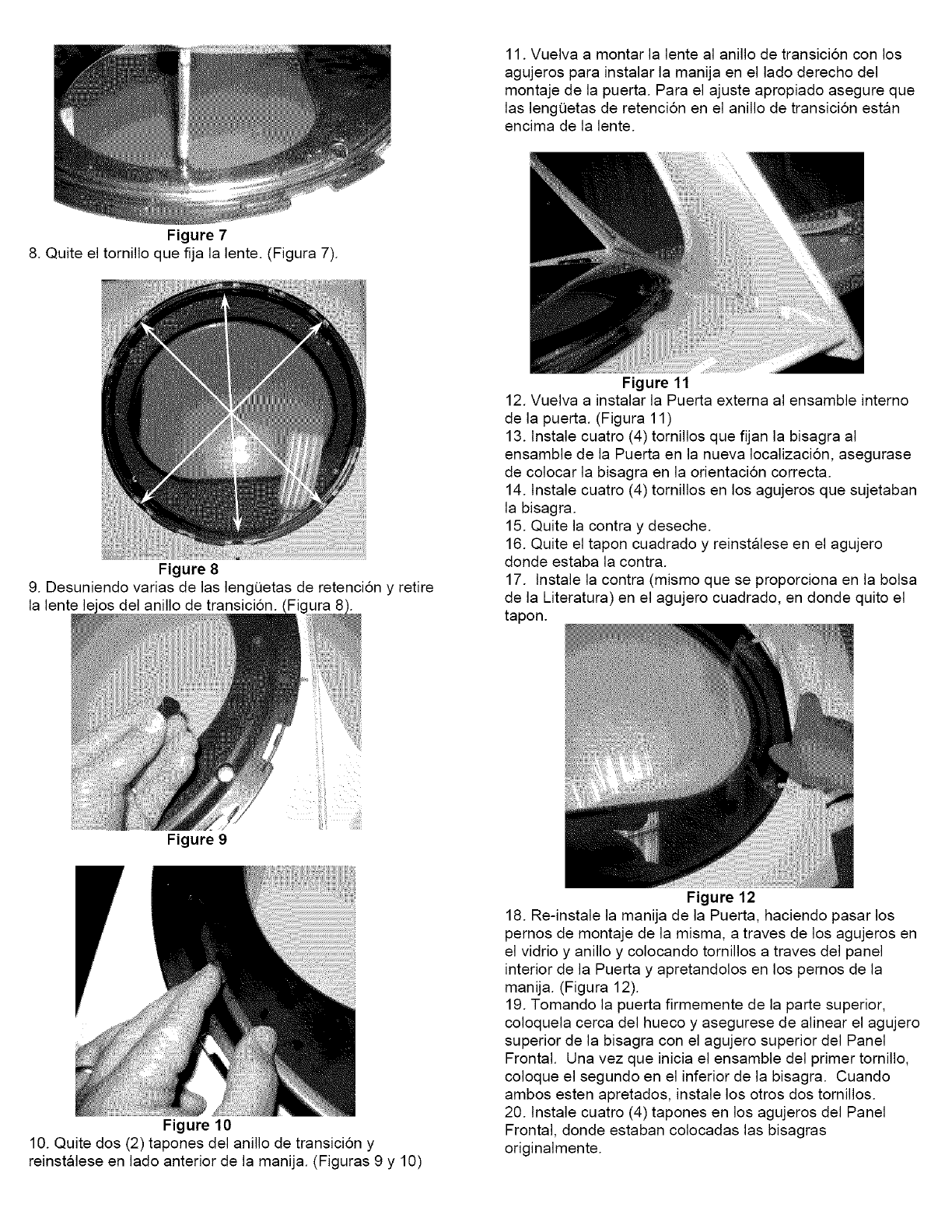
Figure 7
11. Vuelva a montar la lente al anillo de transici6n con los
agujeros para instalar la manija en el lade derecho del
montaje de la puerta. Para el ajuste apropiado asegure que
las lengeetas de retenci6n en el anillo de transici6n estan
encima de la lente.
8. Quite el tornillo que fija la lente. (Figura 7).
Figure 8
9. Desuniendo varias de las lengQetas de retenci6n y retire
la lente le os del anillo de transicion.
Figure 9
Figure 10
Figure 11
12. Vuelva a instalar la Puerta externa al ensamble interne
de la puerta. (Figura 11)
13. lnstale cuatro (4) tornillos que fijan la bisagra al
ensamble de la Puerta en la nueva Iocalizacion, asegurase
de colocar la bisagra en la orientacion correcta.
14. lnstale cuatro (4) tornillos en los agujeros que sujetaban
la bisagra.
15. Quite la contra y deseche.
16. Quite el tapon cuadrado y reinstalese en el agujero
donde estaba la contra.
17. lnstale la contra (mismo que se proporciona en la bolsa
de la Literatura) en el agujero cuadrado, en donde quito el
tapon.
10. Quite dos (2) tapones del anillo de transici6n y
reinstalese en lado anterior de la manija. (Figuras 9 y 10)
Figure 12
18. Re-instale la manija de la Puerta, haciendo pasar los
pernos de montaje de la misma, a traves de los agujeros en
el vidrio y anillo y colocando tornillos a traves del panel
interior de la Puerta y apretandolos en los pernos de la
manija. (Figura 12).
19. Tomando la puerta firmemente de la parte superior,
coloquela cerca del hueco y asegurese de alinear el agujero
superior de la bisagra con el agujero superior del Panel
Frontal. Una vez que inicia el ensamble del primer tornillo,
coloque el segundo en el inferior de la bisagra. Cuando
ambos esten apretados, instale los otros dos tornillos.
20. tnstale cuatro (4) tapones en los agujeros del Panel
Frontal, donde estaban colocadas las bisagras
originalmente.

INSTALA CION ELECTRICA
[ SecadorasELECTR/CAS ]
_F!__ Los siguientes requerimientos son
especificos para el funcionamiento correcto y seguro de su
secadora. El incumplimiento de estas instrucciones puede
causar prolongaci6n excesiva del tiempo de secado y riesgos
de incendio.
Este artefacto DEBE ser puesto a tierra
de manera correcta. Sila secadora no esta debidamente puesta
a tierra se puede producir un choque el_ctrico. Siga las
instrucciones indicadas en este manual para lapuesta a tierra en
forma correcta.
No use un cord6n de extensi6n con
estasecadora. Algunos cordones deextension no pueden soportar
lacantidad de corriente electrica que utiliza estasecadoray pueden
fundirse, creando un peligro de choque el_ctrico y/o incendio.
Ubique lasecadora de manera que el cord6n elOctricoIlegue hasta
el tomacorriente que se va a usar, dejando un poco de holgura
paraelcord0n. Consultelosrequerimientosdeinstalaci0n
preliminares indicados en este manual para el cordon elOctrico
que debe ser adquirido.
F_ Se debe instalar un andaje aprobado
porel U.L. para elcord6n electrico. Si no se utiliza un anclaje
para sujetar el cordon el_ctrico, _ste puede salirse de la secadora
y cortarse con cualquier movimiento, resultando en un choque
el_ctrico.
No utilice un tomacorriente con cables
de aluminio con un cord6n y un enchufe de cobre (o
viceversa). Se produce una reacci0n quimica entre el cobre y el
aluminio que puede causar cortacircuitos. El cableado y
tomacorriente apropiado es un cord6n el_ctrico equipado
con conductores de cobre con un tomacorriente con
conductores de cobre.
Para una secadora conectada permanentemente:
I. La secadora DEBE ser conectada a un sistema de cableado
metalico permanente, puesto a tierra; o se debe instalar un
conductor de puestaatierra deequipojunto con losconductores
del circuito y conectarse al borne de puesta atierra del equipo
o al cable del artefacto.
SecadorasELECTR/CAS Canadienses j
_La conexion indebida del conductor de puesta a
tierra del equipo puede ocasionar un riesgo de choque electrico.
Consulte con un electricista profesional si tiene alguna duda
respecto a la puesta a tierra correcta del artefacto.
Parauna secadora puesta a tierra con cordon electrico:
I. La secadora DEBE ser puesta a tierra. En caso de
malfuncionamiento o falla, la puesta atierra reducir_iel riesgo
de choque electrico proporcionando un trayecto de menor
resistencia a la corriente electrica.
.Sisusecadoraest,1equipada con un cordon electrico que posee
un conductor de puesta a tierra del equipo y un enchufe de
puesta a tierra, dicho enchufe DEBE ser conectado a un
tomacorriente adecuado, debidamente instalado y puesto a
tierra de acuerdo con todos los codigos y reglamentos locales.
Sitiene alguna duda consulte aun electricista profesional. No
modifique el enchufe proporcionado la aplicacion.
ITODAS/assecadoras a GAS I
Estasecadora est,1equipada con un enchufe de tres piernas (de
puesta atierra) para proteccion en contra de choques electricos
y debe ser conectada directamente en un recept_iculo para tres
piernas el cual debe estar puesto a tierra. No corte ni elimine la
espiga de puesta a tierra de este enchufe.
NOTA: Lassecadoras que operan con un suministro de energia
de 208 voltios usaran mas tiempo de secado que aquellas que
operan con un suministro de energia de 240 voltios.
REQUERIMIENTOS PARA LA PUESTA A TIERRA
[ SecadorasEZECTRlCAS ]
_La conexi0n indebida del conductor de puesta
atierra del equipo puede ocasionar un riesgo de choque el_ctrico.
Consulte con un electricistaprofesionalsitiene alguna duda respecto
a la puesta atierra correcta del artefacto.
Para una secadora puesta a tierra, con cord6n electrico:
I. La secadora DEBE ser puesta a tierra. En caso de
malfuncionamiento o falla, la puesta atierra reducira el riesgo
de choque el_ctrico proporcionando un trayecto de menor
resistencia a la corriente el_ctrica.
2. Sisusecadora estaequipada con un cordon el_ctrico que posee
un conductor de puesta a tierra del equipo y un enchufe de
puesta a tierra, dicho enchufe DEBE ser conectado a un
tomacorriente adecuado, debidamente instalado y puesto a
tierra de acuerdo con todos los c0digos y reglamentos locales.
Sitiene alguna duda consulte a un electricista profesional. No
modifique el enchufe proporcionado la aplicaci6n. 21
CONEXIONES ELECTRICAS PARA
UN SISTEMA TRIFILAR
Secadoras ELECTR/CASNo Canadienses i
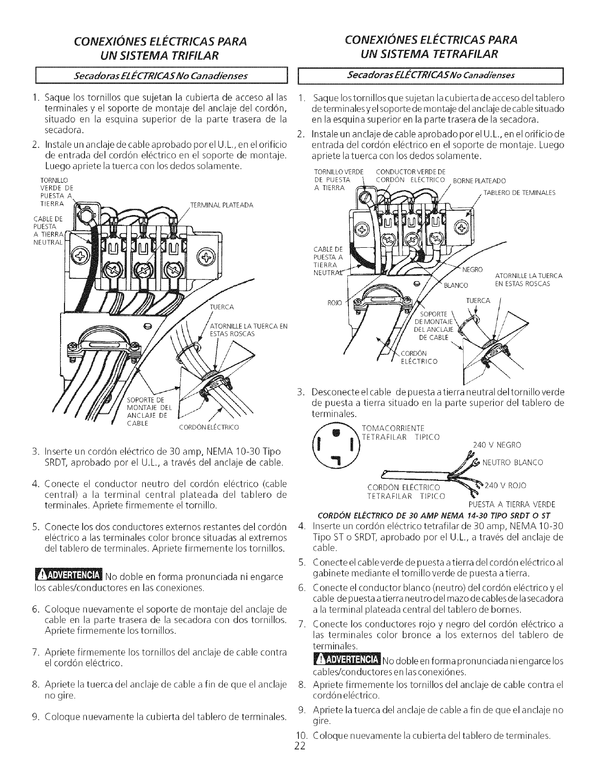
1. Saque los tornillos que sujetan la cubierta de acceso al las
terminales y el soporte de montaje del anclaje del cordon,
situado en la esquina superior de la parte trasera de la
secadora.
2. Instale un anclaje de cable aprobado por el U.L.,en el orificio
de entrada del cordOn elOctrico en el soporte de montaje.
Luego apriete la tuerca con los dedos solamente.
TORNIL[O
VERDE DE
PUESTA A
TIERRA TERMINAL PLATEADA
CABLE DE
PUESTA
A TIERRA
NEUTRAL
TUERCA
ESTASROSCAS
i
1.
CONEXIONES ELECTRICAS PARA
UN SISTEMA TETRAFILAR
Secadoras EL_-CTR/CASNo Canadienses j
Saque los tornillos que sujetan la cubierta de acceso del tablero
determ inalesy elsoporte de montaje del anclaje de cable situado
en laesquina superior en la parte trasera de la secadora.
Instale un anclaje de cable aprobado por el U.L.,en el orificio de
entrada del cordon el_ctrico en el soporte de montaje. Luego
apriete la tuerca con los dedos solamente.
TORNILLO VERDE CONDUCTORVERDE DE
DE PUESTA CORDON ELECTRICO BORNEPLATEADO
A TIERRA /TABLERO DETEMINALES
CABLE DE
PUESTAA
TIERRA
ROJO
_LANCO
TUERCA
SOPORTE \
)E MONTAJE \
DEL ANCLAJE
DE CABLE
CORDON
ELECTRICO
ATORNILLE LA TUERCA
EN ESTASROSCAS
SOPORTEDE
MONTAJE DEL
ANCLAJE DE
CABLE CORDON ELECTRICO
3. Inserte un cord6n elOctrico de 30 amp, NEMA 10-30 Tipo
SRDT,aprobado por el U.L, a travOs del anclaje de cable.
4. Conecte el conductor neutro del cordOn el_ctrico (cable
central) a la terminal central plateada del tablero de
terminales. Apriete firmemente el tornillo.
5. Conecte los dos conductores externos restantes del cordon
el_ctrico a las terminales color bronce situadas al extremos
del tablero de terminales. Apriete firmemente los tornillos.
.
.
No doble en forma pronunciada ni engarce
los cables/conductores en las conexiones. 6.
6. Coloque nuevamente el soporte de montaje del anclaje de
cable en la parte trasera de la secadora con dos tornillos.
Apriete firmemente los tornillos.
7. Apriete firmemente los tornillos del anclaje de cable contra
el cord6n el_ctrico.
8. Apriete la tuerca del anclaje de cable a fin de que el anclaje
no gire.
.
.
9.
10.
22
9. Coloque nuevamente la cubierta del tablero de terminales.
Desconecte el cable de puesta a tierra neutral del tornillo verde
de puesta a tierra situado en la parte superior del tablero de
terminales.
TOMACORRIENTE
TETRAFILAR TIPICO
240 NEGRO
_ NEUTRO BLANCO
X¢ 24°vR°j°
PUESTA A TIERRA VERDE
CORDON ELL:CTRICO DE 30 AMP NEMA 14-30 TIPO SRDT 0 ST
Inserte un cord6n el_ctrico tetrafilar de 30 amp, NEMA 10-30
Tipo ST o SRDT,aprobado por el U.L., a travOs del anclaje de
cable.
Conecte el cable verde de p uesta a tierra del cord6n electrico al
gabinete mediante el tornillo verde de puesta atierra.
Conecte el conductor blanco (neutro) del cord6n el@ctricoy el
cable de puesta atierra neutro del mazo decablesde lasecadora
a la terminal plateada central del tablero de bornes.
Conecte los conductores rojo y negro del cord6n electrico a
las terminales color bronce a los externos del tablero de
terminales.
No doble en forma pronunciada ni engarce los
cables/conductores en lasconexi6nes.
Apriete firmemente los tornillos del anclaje de cable contra el
cord6n el_ctrico.
Apriete la tuerca del anclaje de cable afin de que el anclaje no
gire.
Coloque nuevamente la cubierta del tablero de terminales.
CONEXION DEL GAS
I. Saquelatapa de embarque de latuberia de gas de la secadora
situada en la parte trasera.
NOTA: NO conecte la secadora al suministro de propano, sin
convertir lavalvula del gas. Unjuego de conversion a propano
debe ser instalado por un tecnico de gas calificado.
.Conecte una tuberia semirigida de 1/2" (1,27 cm) D.I. o una
tuberia aprobada, desde la linea de suministro de gas a la
tuberia de 3/8" (0,96 cm) ubicada en la parte trasera de la
secadora (ver paginas 6 y 7). Utilice un reductor de I/2" (1,27
cm) a3/8" (0,96 cm) para la conexiOn. Aplique un sellador de
roscas de uso aprobado, resistente a lacorrosion de los gases
licuados, en todas las uniones de la tuberia.
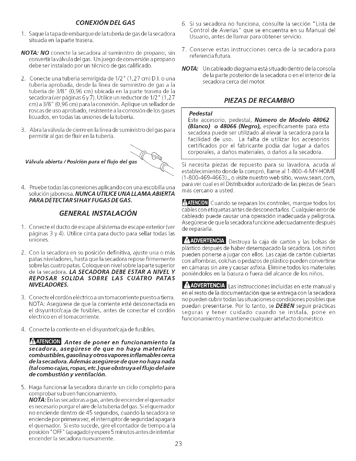
3. Abra la valvula de cierre en lalinea de suministro del gas para
permitir al gas de fluir en la tuberia.
V_lvula abierta / Posicion para el flujo de! gas
4. Pruebe todas las conexiones aplicando con una escobilla una
soluciOnja bonosa. NUNCA UTILICE UNA LLAMA ABIERTA
PARA DETECTAR SIHAY FUGAS DE GAS.
GENERAL INSTALACION
I. Conecte el ducto de escape al sistema de escape exterior (ver
paginas 3 y 4). Utilice cinta para ducto para sellar todas las
uniones.
2. Con la secadora en su posiciOn definitiva, ajuste una o mas
patas niveladores, hasta que la secadora repose firmemente
sobre lascuatro patas. Coloque un nivel sobre laparte superior
de la secadora. LA SECADORA DEBE ESTAR A NIVEL Y
REPOSAR SOLIDA SOBRE LAS CUATRO PATAS
NIVELADORES.
3. Conecte elcordon el_ctrico a un tomacorriente puesto atierra.
NOTA: Aseg0rese de que la corriente est_ desconectada en
el disyuntor/caja de fusibles, antes de conectar el cordon
el_ctrico en el tomacorriente.
6. Si su secadora no funciona, consulte la seccion "Lista de
Control de Averias" que se encuentra en su Manual del
Usuario, antes de Ilamar para obtener servicio.
7. Conserve estas instrucciones cerca de la secadora para
referencia futura.
NOTA: Un cableado diagrama est,1situado dentro de la consola
de la parte posterior de la secadora o en el interior de la
secadora cerca del motor.
PIEZAS DE RECAMB!O
Pedestal
Este accesorio, pedestal, Numero de Modelo 48062
(Blanco) o 48066 (Negro), especificamente para esta
secadora puede ser utilizado al elevar la secadora para la
facilidad de uso. La falta de utilizar los accesorios
certificados por el fabricante podia dar lugar a dahos
corporales, a dahos materiales, o dahos a la secadora.
Si necesita piezas de repuesto para su lavadora, acuda al
establecimiento donde la compro, Ilame al 1-800-4-MY-HOME
(1-800-469-4663)., o visite nuestro web sitio, www.sears.com,
para ver cual es el Distribuidor autorizado de las piezas de Sears
m_iscercano a usted.
Cuando se reparan los controles, marque todos los
cables con etiquetas antes de desconectarlos. Cualquier error de
cableado puede causar una operacion inadecuada y peligrosa.
Aseg0 resede que lasecadora funcione adecuadamente despues
de repararla.
Destruya la caja de carton y las bolsas de
pl_istico despu_s de haber desempacado la secadora. Los nihos
pueden ponerse ajugar con ellos. Lascajas de carton cubiertas
con alfombras, colchas o pedazos de pl_istico pueden convertirse
en c_imarassin aire y causar asfixia. Elimine todos los materiales
poniendolos en la basura o fuera del alcance de los nihos.
Las instrucciones incluidas en este manual y
en el resto de la documentacion que se entrega con la secadora
no pueden cubrir todas lassituaciones o condiciones posibles que
puedan presentarse. Por Io tanto, se DEBEN seguir pr_icticas
seguras y tener cuidado cuando se instala, pone en
funcionamientoy mantiene cualquier artefacto domestico.
4. Conecte la corriente en el disyuntor/caja de fusibles.
Antes de poner en funcionamiento la
secadora, asegurese de que no haya materiales
combustibles, gasolina y otros vapores inflamables cerca
de la secadora. Ademas asegu rese de que no haya nada
(tal como cajas, ropas, etc.) que obstruya el flujo del aire
de combustion y ventilacion.
5. Haga funcionar la secadora durante un ciclo completo para
comprobar su buen funcionamiento.
NOTA: Enlassecadoras agas,antes de encender el quemador
esnecesario purgar el aire de latu beria del gas. Siel quemador
no enciende dentro de 45 segundos, cuando la secadora se
enciende por primera vez, el interruptor de seguridad apagara
el quemador. Siesto sucede, gire el contador de tiempo a la
posiciOn"OFF" (apagado) y espere 5 minutos antes de intentar
encender la secadora nuevamente. 23

Your Home
For repair- in your home - of all major brand appliances,
lawn and garden equipment, or heating and cooling systems,
no matter who made it, no matter who sold it!
For the replacement parts, accessories and
owner's manuals that you need to do-it-yourself.
For Sears professional installation of home appliances
and items like garage door openers and water heaters.
1-800-4-MY-HOME ® (1-800-469-4663)
Call anytime, day or night (U.S.A. and Canada)
www.sears.com www.sears.ca
For expert home solutions advice: www.managemyhome.com
Our Home
For repair of carry-in items like vacuums, lawn equipment,
and electronics, call or go on-line for the location of your nearest
Sears Parts & Repair Service Center
1-800-488-1222 (U.S.A.) 1-800-469-4663 (Canada)
Call anytime, day or night
www.sears.com www.sears.ca
To purchase a protection agreement on a product serviced by Sears:
1-800-827-6655 (U.S.A.)
Para pedir servicio de reparaci6n
a domicilio, y para ordenar piezas:
1-888-SU-HOGAR ®
(1-888-784-6427)
1-800-361-6665 (Canada)
Au Canada pour service en frangais:
1-800-LE-FOYER M°
(1-800-533-6937)
www.sears.ca
Sea//'s
TM SM
® Registered Trademark /Trademark /Service Mark of Sears Brands, LLC
® Mama Registrada /TM Marca de F_brica /s_ Marca de Servicio de Sears Brands, LLC
_,TcMarque de commerce /MDMarque d_pos_e de Sears Brands, LLC ® Sears Brands, LLC
