Kenmore 58075184500 User Manual ROOM A/C Manuals And Guides L0503365
KENMORE Air Conditioner Room (42) Manual L0503365 KENMORE Air Conditioner Room (42) Owner's Manual, KENMORE Air Conditioner Room (42) installation guides
User Manual: Kenmore 58075184500 58075184500 KENMORE ROOM A/C - Manuals and Guides View the owners manual for your KENMORE ROOM A/C #58075184500. Home:Heating & Cooling Parts:Kenmore Parts:Kenmore ROOM A/C Manual
Open the PDF directly: View PDF ![]() .
.
Page Count: 28
Owner's Manual
Manual del Propietario
®
HEAT /COOL AIR CONDITIONER
EICALOR /REFRESCA ACONDICIONADOR
DE AIRE DE VENTANA
Model, Modelo 580.75184
Sears, Roebuck and Co., Hoffman Estates, IL 60179 U.S.A.
www.sears.com
TABLE OF CONTENTS ........................2
WARRANTY ..............................................2
SAFETY .....................................................3
Important Safety Instructions...................... 3
ELECTRICAL REQUIREMENTS .......4
INSTALLATION ........................................5
Installation Requirements ......................... 5
Installation ................................................ 6
How to Install............................................ 6
Removal from Window ................................. 8
OPERATION .............................................9
How and Why ........................................... 9
Normal Sounds ........................................ 9
Capacity and Running Time ..................... 9
Features ................................................. 10
Using the Air Conditioner ....................... 10
Display ................................................... 11
MAINTENANCE .....................................12
Air Filter Cleaning ................................... 12
Air Conditioner Cleaning ........................ 12
How to Replace the Front Grille .................. 12
TROUBLESHOOTING .........................13
Before Calling for Service ...................... 13
ESPANOL ................................................14
MASTER PROTECTION
AGREEMENTS ........................................27
SERVICE NUMBERS ....... Back Cover
FULL ONE YEAR WARRANTY ON
ROOM AIR CONDITIONER
For one year from the date of purchase, when this
air conditioner is operated and maintained for
normal room cooling according to the instructions in
this owner's manual, Sears will repair this air
conditioner, free of charge, if defective in material or
workmanship.
FULL FIVE-YEAR WARRANTY ON
SEALED REFRIGERATION SYSTEM
For five years from the date of purchase, when this
air conditioner is operated and maintained for
normal room cooling according to the instructions in
this owner's manual, Sears will repair the sealed
refrigeration system (consisting of refrigerant,
connecting tubing, and compressor), free of charge,
if defective in material or workmanship.
WARRANTY SERVICE IS AVAILABLE BY
CONTACTING SEARS SERVICE AT
1-800-4-MY-HOME ®
Warranty coverage applies only to air conditioners
used for non-commercial, private household
purposes.
This warranty applies only while this product is in
use in the United States.
This warranty gives you specific legal rights, and
you may also have other right which vary from state
to state.
Sears, Roebuck and Co., D/817WA,
Hoffman Estates, IL 60179 U.S.A.
-2-
IMPORTANT SAFETY INSTRUCTIONS
The safety instructions below will tell you how to use your room air conditioner to avoid harm to yourself or
damage to your ROOM AIR CONDITIONER.
FOR YOUR SAFETY
Do not store or use gasoline or other flammable
vapors and liquids in the vicinity of this or any other
appliance. Read product labels for flammability and
other warnings.
PREVENT ACCIDENTS
To reduce the risk of fire, electrical shock, or injury
to persons when using your air conditioner, follow
basic precautions, including the following:
• Be sure the electrical service is adequate for the
model you have chosen.
• If the air conditioner is to be installed in a window,
you will probably want to clean both sides of the
glass first. If the window is a triple-track type with a
screen panel included, you may want to remove
the screen completely before installation.
• Be sure the air conditioner has been securely and
correctly installed according to the separate
installation instructions provided with this manual.
Save this manual and installation instructions for
possible future use in removing or reinstalling this
unit.
• Use gloves when handling the air conditioner.
Be careful to avoid cuts from sharp metal fins on
front and rear coils.
V.'_V_Vl-'1;i_ll_[qELECTRICAL INFORMATION
The complete electrical rating of your new room air
conditioner is stated on the serial plate. Refer to the
rating when checking the electrical requirements.
• Be sure the air conditioner is properly grounded.
To minimize shock and fire hazards, proper
grounding is important. The power cord is
equipped with a three-prong grounding plug for
protection against shock hazards.
• Your air conditioner must be plugged into a
properly grounded wall receptacle. If the wall
receptacle you intend to use is not adequately
grounded or protected by a time delay fuse or
circuit breaker, have a qualified electrician install
the proper receptacle.
• Do not run air conditioner with a protective
covering. This could result in mechanical damage
within the air conditioner.
• Do not use an extension cord or an adapter
plug.
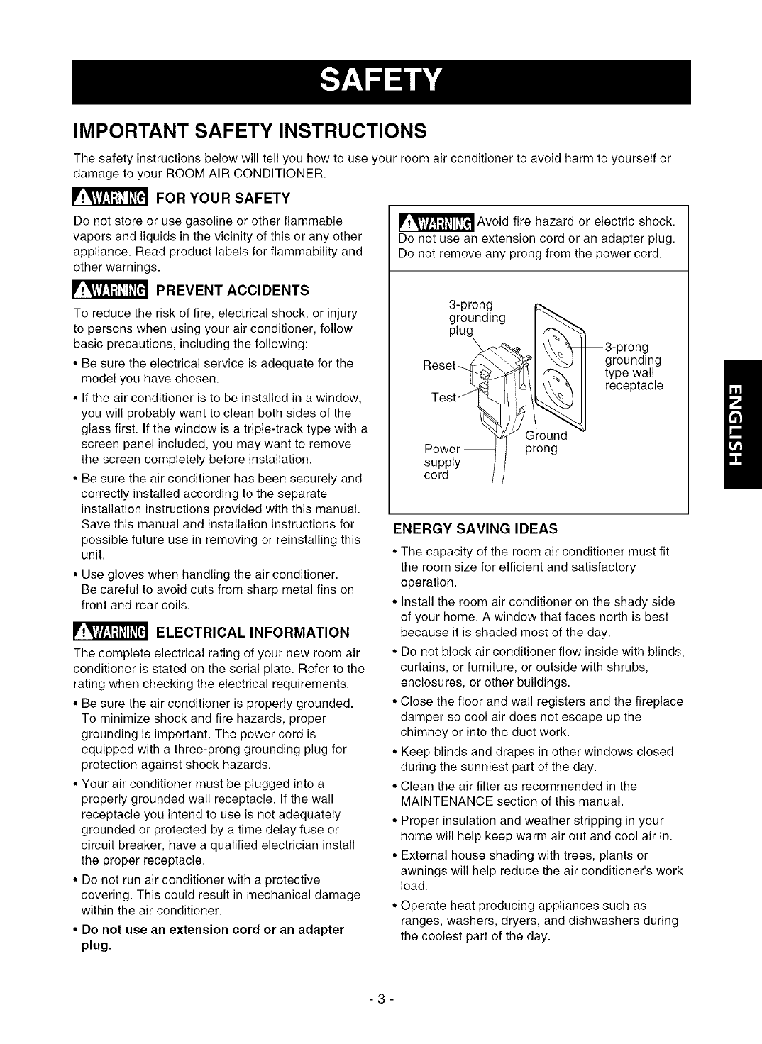
_Avoid fire hazard or electric shock.
Do not use an extension cord or an adapter plug.
Do not remove any prong from the power cord.
3-prong
grounding I _
plug J /f'_"_-
eset_ l
_ Ground
Power_ I prong
supply ]1
cord //
--3-prong
grounding
type wall
receptacle
ENERGY SAVINGIDEAS
• The capacity of the room air conditioner must fit
the room size for efficient and satisfactory
operation.
• Install the room air conditioner on the shady side
of your home. A window that faces north is best
because it is shaded most of the day.
• Do not block air conditioner flow inside with blinds,
curtains, or furniture, or outside with shrubs,
enclosures, or other buildings.
• Close the floor and wall registers and the fireplace
damper so cool air does not escape up the
chimney or into the duct work.
• Keep blinds and drapes in other windows closed
during the sunniest part of the day.
• Clean the air filter as recommended in the
MAINTENANCE section of this manual.
• Proper insulation and weather stripping in your
home will help keep warm air out and cool air in.
• External house shading with trees, plants or
awnings will help reduce the air conditioner's work
load.
• Operate heat producing appliances such as
ranges, washers, dryers, and dishwashers during
the coolest part of the day.
-3-
OBSERVE ALL LOCAL CODES AND
ORDINANCES.
DO NOT, UNDER ANY CIRCUMSTANCES,
REMOVE THE POWER SUPPLY CORD
GROUND PRONG.
ELECTRICAL GROUND IS REQUIRED ON
THIS APPLIANCE.
A 250-volt 60 Hz, AC only, 20A fused and
properly grounded electrical supply is required.
A time delay fuse or time delay circuit breaker
is recommended. Use a dedicated circuit,
serving only this appliance.
DO NOT USE AN EXTENSION CORD.
RECOMMENDED GROUNDING METHOD
For your personal safety, this appliance must
be grounded. This appliance has a power
supply cord with a 3-prong grounding plug. To
minimize possible shock hazard, the cord must
be plugged into a mating grounding type wall
receptacle and grounded in accordance with
the National Electrical Code (ANSl/NFPA 70)
latest edition and all local codes and
ordinances. If a mating wall receptacle is not
available, it is the personal responsibility and
obligation of the customer to have a properly
grounded 3-prong wall receptacle installed by a
qualified electrician.
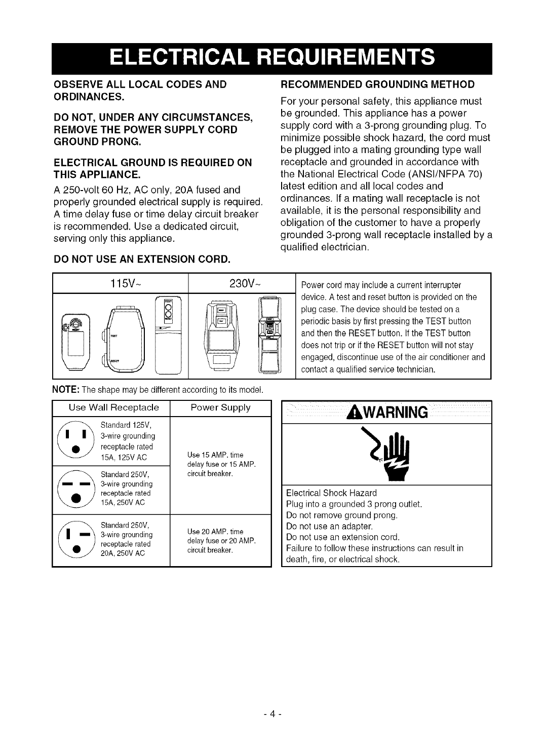
115V~ 230V~ Power cord may include a current interrupter
device. A test and reset button is provided on the
plug case. The device should be tested on a
periodic basis by first pressing the TEST button
and then the RESET button. If the TEST button
does not trip or if the RESET button will not stay
engaged, discontinue use of the air conditioner and
contact a qualified service technician.
NOTE: The shape may be different according to its model.
Use Wall Receptacle Power Supply
_) tandard 125V,
3-wire grounding
receptacle rated
15A, 125V AC
Standard 250V,
3-wire grounding
receptacle rated
15A,250V AC
Standard 250V,
3-wire grounding
receptacle rated
20A, 250V AC
Use 15 AMP. time
delay fuse or 15 AMP.
circuit breaker.
Use 20 AMP. time
delay fuse or 20 AMP.
circuit breaker.
Electrical Shock Hazard
Plug into a grounded 3 prong outlet.
Do not remove ground prong.
Do not use an adapter.
Do not use an extension cord.
Failure to follow these instructions can result in
death, fire, or electrical shock.
-4-
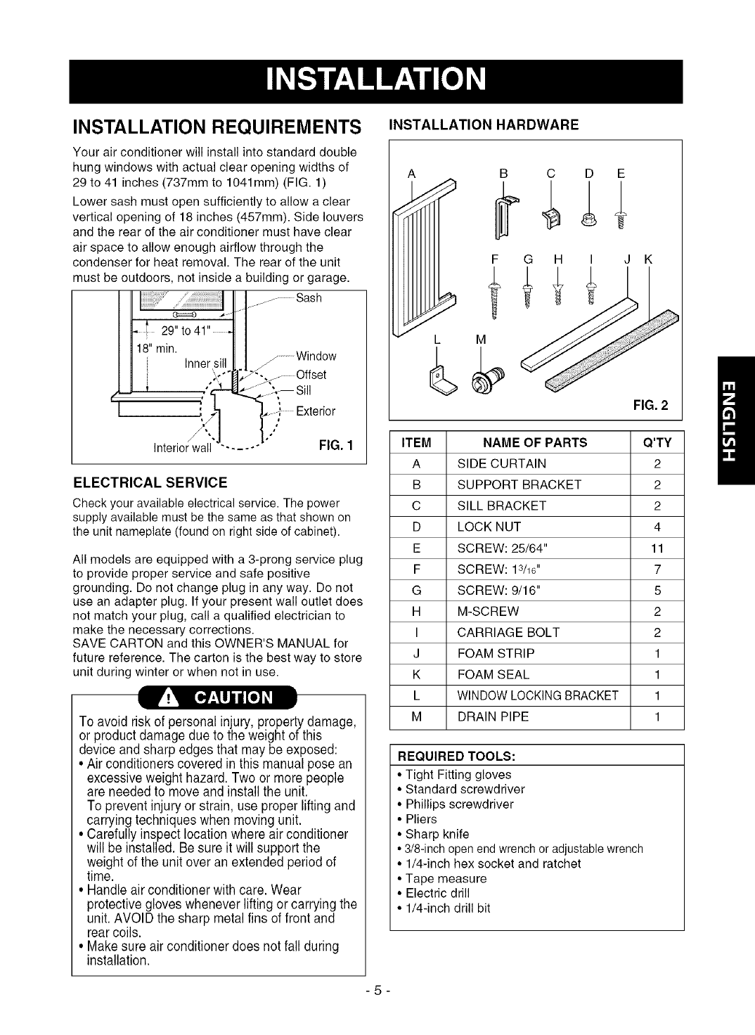
INSTALLATION REQUIREMENTS
Your air conditioner will install into standard double
hung windows with actual clear opening widths of
29 to 41 inches (737mm to 1041mm) (FIG. 1)
Lower sash must open sufficiently to allow a clear
vertical opening of 18 inches (457mm). Side louvers
and the rear of the air conditioner must have clear
air space to allow enough airflow through the
condenser for heat removal. The rear of the unit
must be outdoors, not inside a building or garage.
-1......... Sash
I _ Window
:°Ifset
Exterior
Interior wall "- .... ° FIG. 1
ELECTRICAL SERVICE
Check your available electrical service. The power
supply available must be the same as that shown on
the unit nameplate (found on right side of cabinet).
All models are equipped with a 3-prong service plug
to provide proper service and safe positive
grounding. Do not change plug in any way. Do not
use an adapter plug. If your present wall outlet does
not match your plug, call a qualified electrician to
make the necessary corrections.
SAVE CARTON and this OWNER'S MANUAL for
future reference. The carton is the best way to store
unit during winter or when not in use.
V!_ [o.7:_U]lII[o] _
To avoid risk of personal injury, property damage,
or product damage due to the weight of this
device and sharp edges that may be exposed:
• Air conditioners covered in this manual pose an
excessive weight hazard. Two or more people
are needed to move and install the unit.
To prevent injury or strain, use proper lifting and
carrying techniques when moving unit.
• Carefully inspect location where air conditioner
will be installed. Be sure it will support the
weight of the unit over an extended period of
time.
• Handle air conditioner with care. Wear
protective gloves whenever lifting or carrying the
unit. AVOID the sharp metal fins of front and
rear coils.
• Make sure air conditioner does not fall during
installation.
INSTALLATION HARDWARE
A B C D E
G H I J K
FIG. 2
ITEM NAME OF PARTS Q'TY
A SIDE CURTAIN 2
B SUPPORT BRACKET 2
C SILL BRACKET 2
D LOCK NUT 4
E SCREW: 25/64" 11
F SCREW: 13/16'' 7
G SCREW: 9/16" 5
H M-SCREW 2
I CARRIAGE BOLT 2
J FOAM STRIP 1
K FOAM SEAL 1
L WINDOW LOCKING BRACKET 1
M DRAIN PIPE 1
REQUIRED TOOLS:
• Tight Fitting gloves
• Standard screwdriver
• Phillips screwdriver
• Pliers
• Sharp knife
• 3/8-inch open end wrench or adjustable wrench
• 1/4-inch hex socket and ratchet
• Tape measure
• Electric drill
• 1/4-inch drill bit
-5-
INSTALLATION
Pick a location which will allow you to blow the cold air
into the area you want. Windows used for installation
must be strong enough to support the weight of the air
conditioner. Good installation with special attention to the
proper position of the unit will lessen the chance that
service will be needed.
When cooling more than one room, installation location is
very important. If air conditioner is blocked by a storm
window frame, see step 16on page 8 before beginning to
install. To cool your rooms, cold air must be blown from
the air conditioner in a straight path.
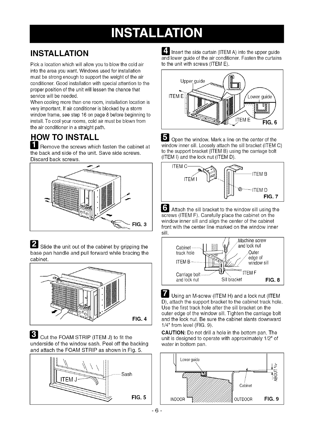
HOW TO INSTALL
H Remove the screws which fasten the cabinet at
the back and side of the unit. Save side screws.
Discard back screws.
FIG. 3
I_11 Slide the unit out of the cabinet by gripping the
base pan handle and pull forward while bracing the
cabinet.
FIG. 4
I_Cut the FOAM STRIP (ITEM J) to fit the
underside of the window sash. Peel off the backing
and attach the FOAM STRIP as shown in Fig. 5.
.... Sash
FIG. 5
L_ Insert the side curtain (ITEM A) into the upper guide
and lower guide of the air conditioner. Fasten the curtains
to the unit with screws (ITEM E).
Upper[g
FIG. 6
I_'_ Open the window. Mark a line on the center of the
window inner sill. Loosely attach the sill bracket (ITEM C)
to the support bracket (ITEM B) using the carriage bolt
(ITEM I) and the lock nut (ITEM D).
ITEM
ITEMI
r_ Attach the sill bracket to the window sill using the
screws (ITEM F). Carefully place the cabinet on the
window inner sill and align the center of the cabinet
front with the center line marked on the window inner
sill.
/Machine screw
Cabinet , /and locknut
trackhole .Outer
_edge of
iT windowsill
Carriagebott................
andlocknut Sill bracket FIG. 8
H Using an M-screw (ITEM H) and a lock nut (ITEM
D), attach the support bracket to the cabinet track hole.
Use the first track hole after the sill bracket on the
outer edge of the window sill. Tighten the carriage bolt
and the lock nut. Be sure the cabinet slants downward
1/4" from level (FIG. 9).
CAUTION: Do not drill a hole in the bottom pan. The
unit is designed to operate with approximately 1/2" of
water in bottom pan.
Lowerguide
INDOOR
Cabinet
OUTDOOR FIG. 9
-6-
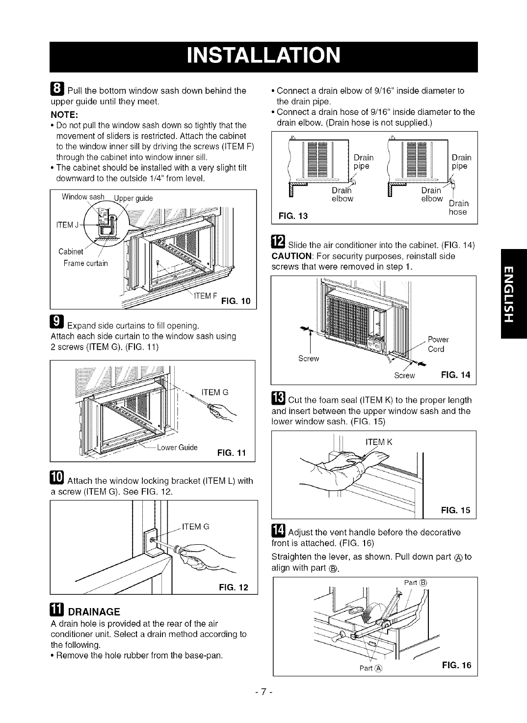
l_ Pull the bottom window sash down behind the
upper guide until they meet.
NOTE:
• Do net pull the window sash down so tightly that the
movement of sliders is restricted. Attach the cabinet
to the window inner sill by driving the screws (ITEM F)
through the cabinet into window inner sill.
• The cabinet should be installed with a very slight tilt
downward to the outside 1/4" from level.
Windowsash Ipperguide
R
Cabinet x
Frame curtain
FIG. 10
_ Expand side curtains to fill opening.
Attach each side curtain to the window sash using
2 screws (ITEM G). (FIG. 11)
FIG. 11
_1_ Attach the window locking bracket (ITEM L) with
a screw (ITEM G). See FIG. 12.
FIG. 12
[] DRAINAGE
A drain hole is provided at the rear of the air
conditioner unit. Select a drain method according to
the following.
• Remove the hole rubber from the base-pan.
• Connect a drain elbow of 9/16" inside diameter to
the drain pipe.
• Connect a drain hose of 9/16" inside diameter to the
drain elbow. (Drain hose is not supplied.)
FIG. 13
elbow elbow [
hose
_"_ Slide the air conditioner into the cabinet. (FIG. 14)
CAUTION: For security purposes, reinstall side
screws that were removed in step 1.
Cord
Screw
Screw FIG. 14
_-] Cut the foam seal (ITEM K) to the proper length
and insert between the upper window sash and the
lower window sash. (FIG. 15)
FIG. 15
_] Adjust the vent handle before the decorative
front is attached. (FIG. 16)
Straighten the lever, as shown. Pull down part ®to
align with part (_.
Part _B_
Pa_@ FIG. 16
-7-
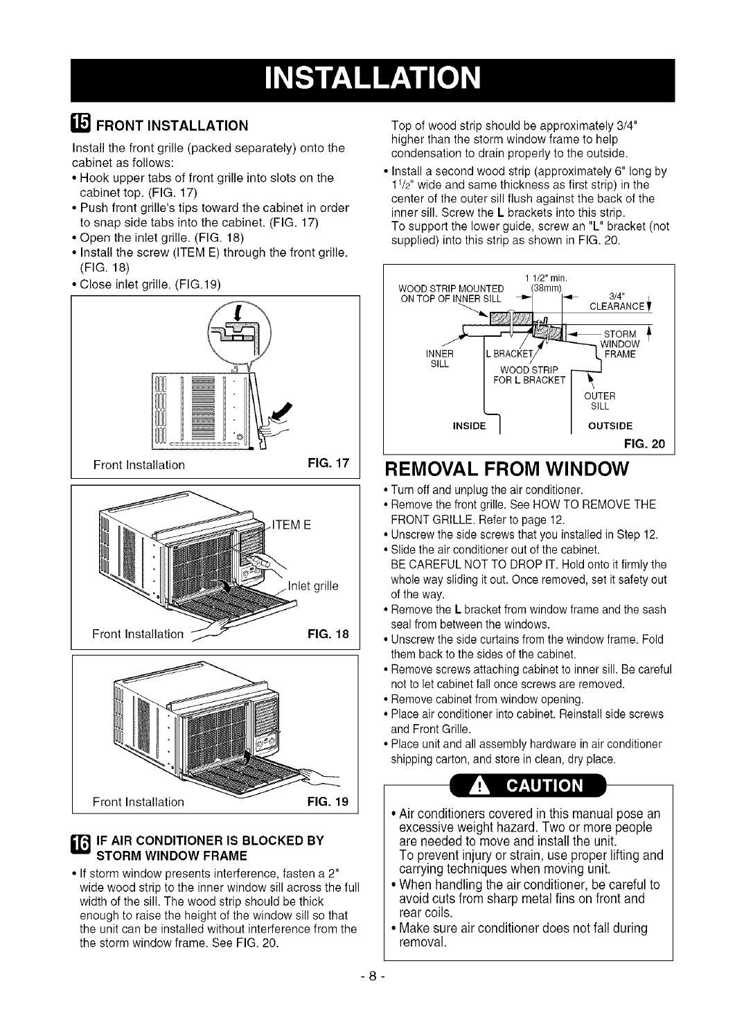
FRONT INSTALLATION
Install the front grille (packed separately) onto the
cabinet as follows:
• Hook upper tabs of front grille into slots on the
cabinet top. (FIG. 17)
• Push front grille's tips toward the cabinet in order
to snap side tabs into the cabinet. (FIG. 17)
• Open the inlet grille. (FIG. 18)
• Install the screw (ITEM E) through the front grille.
(FIG. 18)
• Close inlet grille. (FIG.19)
Front Installation FIG. 17
Front Installation FIG. 18
_!_ [*.7:_ij i [*] _I
Front Installation FIG. 19
_T,_ IF AIR CONDITIONER IS BLOCKED BY
STORM WINDOW FRAME
• If storm window presents interference, fasten a 2"
wide wood strip to the inner window sill across the full
width of the sill. The wood strip should be thick
enough to raise the height of the window sill so that
the unit can be installed without interference from the
the storm window frame. See FIG. 20.
Top of wood strip should be approximately 3/4"
higher than the storm window frame to help
condensation to drain properly to the outside.
• Install a second wood strip (approximately 6" long by
11/2"wide and same thickness as first strip) in the
center of the outer sill flush against the back of the
inner sill. Screw the L brackets into this strip.
To support the lower guide, screw an "L" bracket (not
supplied) into this strip as shown in FIG. 20.
1 1/2" min.
WOOD STRIP MOUNTED (38mm)
ON TOP OF INNER SILL _"1 I_'= 3/4" /
"''_ _ I CLEARANOE_
v
INNER IL BRACKET/ _ FRAME
SILL FWRO0D_TR/P t [_._ j
I I OUTER
L} I SILL
INSIDEI I OUTSNDE
FIG. 20
REMOVAL FROM WINDOW
•Turn off and unplug the air conditioner.
• Remove the front grille. See HOW TO REMOVE THE
FRONT GRILLE. Refer to page 12.
• Unscrew the side screws that you installed in Step 12.
• Slide the air conditioner out ofthe cabinet.
BE CAREFUL NOT TO DROP IT. Hold onto it firmly the
whole way sliding it out. Once removed, set it safety out
of the way.
• Remove the L bracket from window frame and the sash
seal from between the windows.
• Unscrew the side curtains from the window frame. Fold
them back to the sides of the cabinet.
• Remove screws attaching cabinet to inner sill. Be careful
not to let cabinet fall once screws are removed.
• Remove cabinet from window opening.
• Place air conditioner into cabinet. Reinstall side screws
and Front Grille.
• Place unit and all assembly hardware in air conditioner
shipping carton, and store in clean, dry place.
• Air conditioners covered in this manual pose an
excessive weight hazard. Two or more people
are needed to move and install the unit.
To prevent injury or strain, use proper lifting and
carrying techniques when moving unit.
• When handling the air conditioner, be careful to
avoid cuts from sharp metal fins on front and
rear coils.
• Make sure air conditioner does not fall during
removal.
-8-
HOW AND WHY
Your room air conditioner provides the following
functions to make hot weather living more
comfortable:
•Cools and circulates room air.
• Lowers humidity by removing excess moisture.
• Filters out summertime dust, dirt, and some
airborne impurities.
The air conditioner performs these functions by
drawing room air through a filter which traps dust
and dirt particles. The air then passes over a
cooling coil which refrigerates the air and removes
excess moisture. The same air is then returned to
the room-cooler, drier, and cleaner. Moisture
removed from the room air is carried to the outside
and evaporated.
Your air conditioner is designed to be easy to
operate and to provide plenty of cooling power.
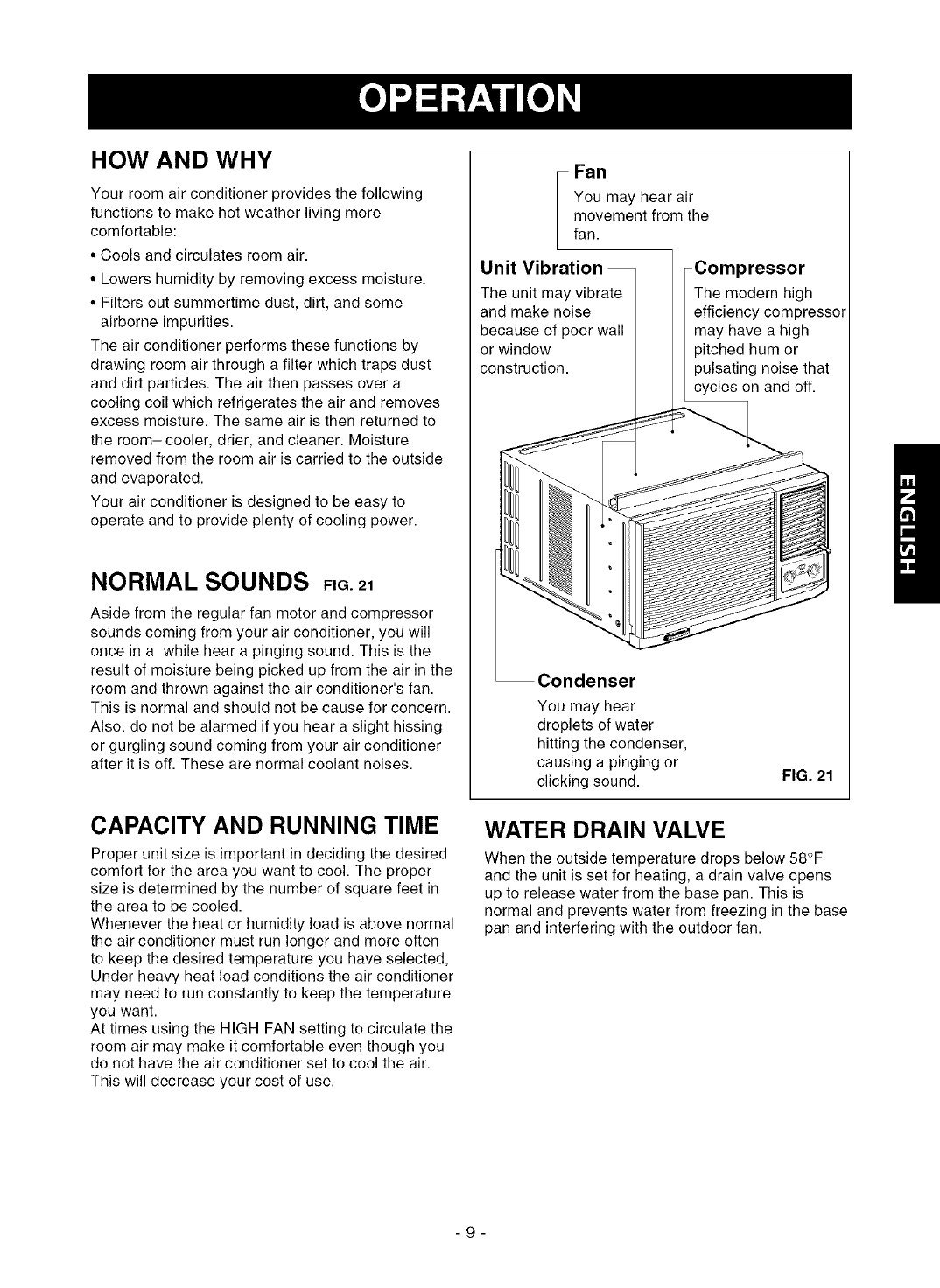
NORMAL SOUNDS FiG.21
Aside from the regular fan motor and compressor
sounds coming from your air conditioner, you will
once in a while hear a pinging sound. This is the
result of moisture being picked up from the air in the
room and thrown against the air conditioner's fan.
This is normal and should not be cause for concern.
Also, do not be alarmed if you hear a slight hissing
or gurgling sound coming from your air conditioner
after it is off. These are normal coolant noises.
CAPACITY AND RUNNING TIME
Proper unit size is important in deciding the desired
comfort for the area you want to cool. The proper
size is determined by the number of square feet in
the area to be cooled.
Whenever the heat or humidity load is above normal
the air conditioner must run longer and more often
to keep the desired temperature you have selected,
Under heavy heat load conditions the air conditioner
may need to run constantly to keep the temperature
you want.
At times using the HIGH FAN setting to circulate the
room air may make it comfortable even though you
do not have the air conditioner set to cool the air.
This will decrease your cost of use.
Fan
You may hear air
movement from the
fan.
Unit Vibration
The unit may vibrate
and make noise
because of poor wall
or window
construction.
Compressor
The modern high
efficiency compressor
may have a high
pitched hum or
pulsating noise that
cycles on and off.
Condenser
You may hear
droplets of water
hitting the condenser,
causing a pinging or
clicking sound. FIG. 21
WATER DRAIN VALVE
When the outside temperature drops below 58°F
and the unit is set for heating, a drain valve opens
up to release water from the base pan. This is
normal and prevents water from freezing in the base
pan and interfering with the outdoor fan.
-9-
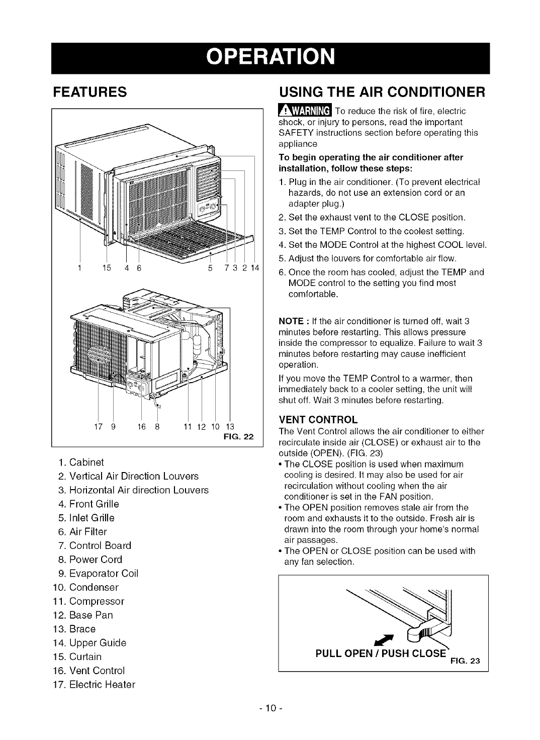
FEATURES
1 15 4 6 5 73 214
17 9 16 8 11 12 10 13
FIG. 22
1. Cabinet
2. Vertical Air Direction Louvers
3. Horizontal Air direction Louvers
4. Front Grille
5. Inlet Grille
6. Air Filter
7. Control Board
8. Power Cord
9. Evaporator Coil
10. Condenser
11. Compressor
12. Base Pan
13. Brace
14. Upper Guide
15. Curtain
16. Vent Control
17. Electric Heater
USING THE AIR CONDITIONER
_To reduce the risk of fire, electric
shock, or injury to persons, read the important
SAFETY instructions section before operating this
appliance
To begin operating the air conditioner after
installation, follow these steps:
1. Plug in the air conditioner. (To prevent electrical
hazards, do not use an extension cord or an
adapter plug.)
2. Set the exhaust vent to the CLOSE position.
3. Set the TEMP Control to the coolest setting.
4. Set the MODE Control at the highest COOL level.
5. Adjust the louvers for comfortable air flow.
6. Once the room has cooled, adjust the TEMP and
MODE control to the setting you find most
comfortable.
NOTE :If the air conditioner is turned off, wait 3
minutes before restarting. This allows pressure
inside the compressor to equalize. Failure to wait 3
minutes before restarting may cause inefficient
operation.
If you move the TEMP Control to a warmer, then
immediately back to a cooler setting, the unit will
shut off. Wait 3 minutes before restarting.
VENT CONTROL
The Vent Control allows the air conditioner to either
recirculate inside air (CLOSE) or exhaust air to the
outside (OPEN). (FIG. 23)
• The CLOSE position is used when maximum
cooling is desired. It may also be used for air
recirculation without cooling when the air
conditioner is set in the FAN position.
• The OPEN position removes stale air from the
room and exhausts it to the outside. Fresh air is
drawn into the room through your home's normal
air passages.
• The OPEN or CLOSE position can be used with
any fan selection.
PULL
FIG. 23
-10-
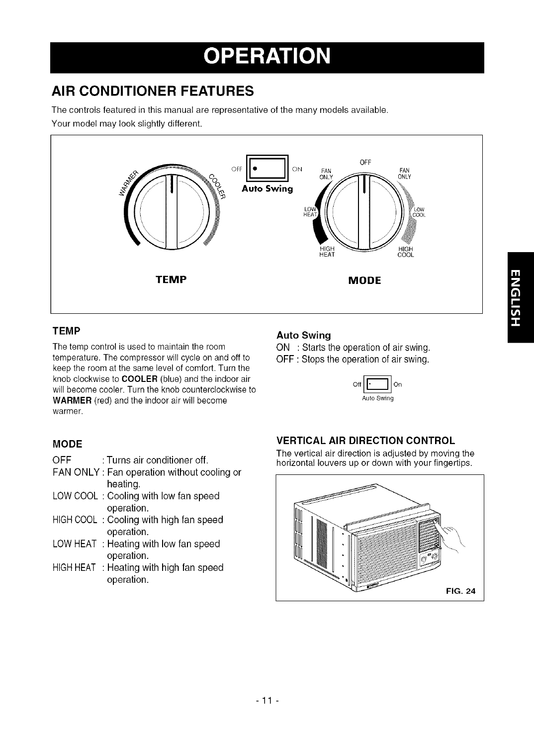
AIR CONDITIONER FEATURES
The controls featured in this manual are representative of the many models available.
Your model may look slightly different.
OFF ON
Auto Swing
OFF
FAN FAN
ONLY T'_ONLY
'i 'LOW
_LOOL
HIGH _
HEAT COOL
TEMP MODE
TEMP
The temp control is used to maintain the room
temperature. The compressor will cycle on and off to
keep the room at the same level of comfort. Turn the
knob clockwise to COOLER (blue) and the indoor air
will become cooler. Turn the knob counterclockwise to
WARMER (red) and the indoor air will become
warmer.
Auto Swing
ON : Starts the operation of air swing.
OFF : Stops the operation of air swing.
On
Auto Swing
MODE
OFF : Turns air conditioner off.
FAN ONLY : Fan operation without cooling or
heating.
LOWCOOL : Cooling with low fan speed
operation.
HIGHCOOL : Cooling with high fan speed
operation.
LOW HEAT : Heating with low fan speed
operation.
HIGHHEAT : Heating with high fan speed
operation.
VERTICAL AIR DIRECTION CONTROL
The vertical air direction is adjusted by moving the
horizontal louvers up or down with your fingertips.
FIG. 24
-11 -
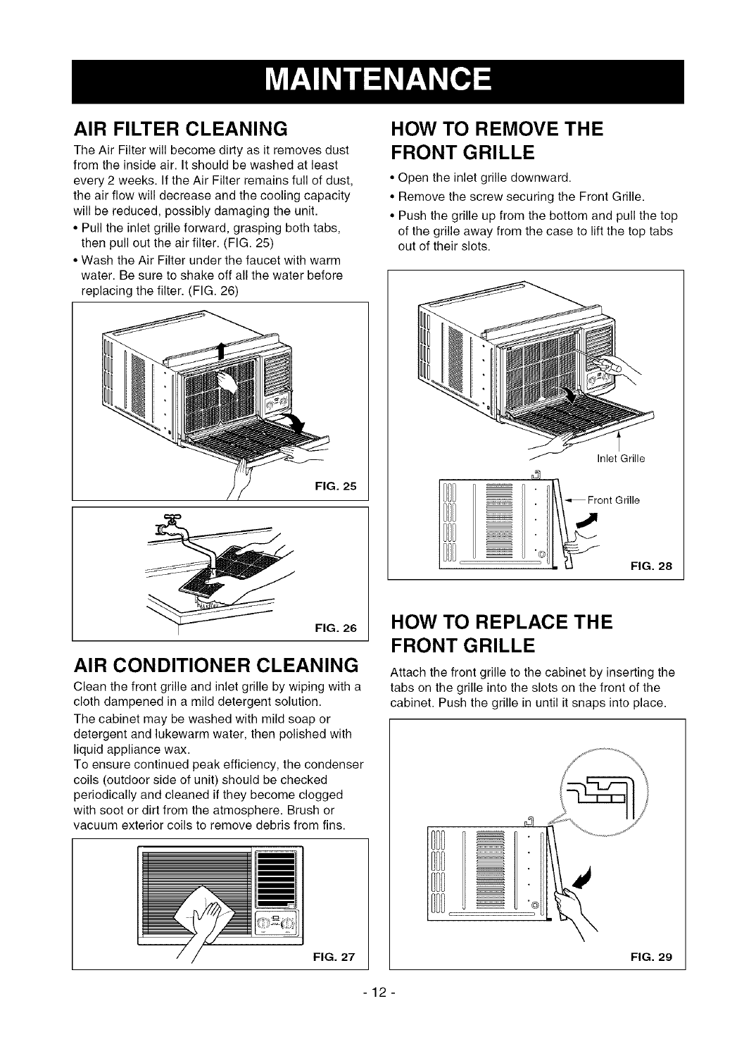
AIR FILTER CLEANING
The Air Filter will become dirty as it removes dust
from the inside air. It should be washed at least
every 2 weeks. If the Air Filter remains full of dust,
the air flow will decrease and the cooling capacity
will be reduced, possibly damaging the unit.
• Pull the inlet grille forward, grasping both tabs,
then pull out the air filter. (FIG. 25)
• Wash the Air Filter under the faucet with warm
water. Be sure to shake off all the water before
replacing the filter. (FIG. 26)
FIG. 25
FIG. 26
AIR CONDITIONER CLEANING
Clean the front grille and inlet grille by wiping with a
cloth dampened in a mild detergent solution.
The cabinet may be washed with mild soap or
detergent and lukewarm water, then polished with
liquid appliance wax.
To ensure continued peak efficiency, the condenser
coils (outdoor side of unit) should be checked
periodically and cleaned if they become clogged
with soot or dirt from the atmosphere. Brush or
vacuum exterior coils to remove debris from fins.
FIG. 27
HOW TO REMOVE THE
FRONT GRILLE
• Open the inlet grille downward.
• Remove the screw securing the Front Grille.
• Push the grille up from the bottom and pull the top
of the grille away from the case to lift the top tabs
out of their slots.
Inlet Grille
4
_.i_°nt GrillilG. 28
HOW TO REPLACE THE
FRONT GRILLE
Attach the front grille to the cabinet by inserting the
tabs on the grille into the slots on the front of the
cabinet. Push the grille in until it snaps into place.
FIG. 29
-12-
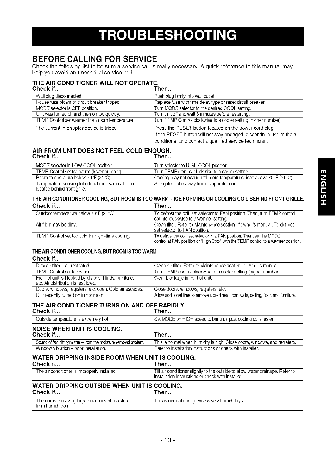
BEFORE CALLING FOR SERVICE
Check the following list to be sure a service call is really necessary. A quick reference to this manual may
help you avoid an unneeded service call.
THE AIR CONDITIONER WILL NOT OPERATE.
Check if...
Wall plug disconnected.
House fuse blown or circuit breaker tripped.
MODE selector isOFF position.
Unit was turned off and then on too quickly.
TEMP Control set warmer than room temperature.
The current interrupter device is triped
Then...
Push plugfirmly into wall outlet.
Replace fuse with time delay type or reset circuit breaker.
Turn MODE selector to the desired COOL setting.
Turn unit off and wait 3 minutes before restarting.
Turn TEMP Control clockwise to a cooler setting (higher number).
Press the RESET button located on the power cord plug
If the RESET button will not stay engaged, discontinue use of the air
conditioner and contact a qualified service technician.
AIR FROM UNIT DOES NOT FEEL COLD ENOUGH.
Check if... Then...
MODE selector in LOW COOL position.
TEMP Control set too warm (lower number).
Room temperature below 70F (21°C).
Temperature sensing tube touching evaporator coil,
located behind front grille.
Turn selector to HIGH COOL position
Turn TEMP Control clockwise to a cooler setting.
Cooling may not occur until room temperature rises above 70°F (21°C).
Straighten tube away from evaporator coil.
THE AIR CONDITIONER COOLING, BUT ROOM IS TOO WARM - ICE FORMING ON COOLING COIL BEHIND FRONT GRILLE.
Check if... Then...
Outdoor temperature below 70_'F(21_'C). To defrost the coil, set selector to FAN position.Then, turn TEMP control
counterclockwise to a warmer setting.
Air filter may be dirty. Clean filter. Refer to Maintenance section of owner's manual. To defrost,
set selector to FAN position.
TEMP Control set too cold for night-time cooling. Todefrostthe coil,setselectorto a FAN position.Then,set theMODE
controlat FANpositionor "HighCool" withthe TEMPcontrolto a warmerposition.
THEAIRCONDITIONERCOOLING, BUT ROOM ISTOO WARM.
Check if...
Dirty air filter- air restricted. Clean air filter. Refer to Maintenance section of owner's manual.
TEMP Control set too warm. Turn TEMP control clockwiseto a cooler setting (higher number).
Front of unit is blocked by drapes, blinds,furniture, Clear blockage in front of unit.
etc. Air distribution is restricted.
Doors, windows, registers, etc. open. Cold air escapes. Close doors, windows, registers, etc.
Unit recently turned on in hot room. Allowadditionaltimeto removestoredheatfromwalls,ceiling,floor,andfurniture.
THE AIR CONDITIONER TURNS ON AND OFF RAPIDLY.
Check if... Then...
IOutside temperature is extremely hot. iSet MODE on HIGH speedto bring air pastcooling coils faster, i
NOISE WHEN UNIT IS COOLING.
Check if... Then...
[ Soundoffan hittingwater- fromthe moistureremovalsystem, t This is normal when humidity is high. Closedoors, windows, and registers, t
Window vibration - poor installation. Refer to installation instructions or check with installer.
WATER DRIPPING INSIDE ROOM WHEN UNIT IS COOLING.
Check if... Then...
The air conditioner isimproperly installed. Tilt air conditioner slightly to the outside to allow water drainage. Refer to
installation instructions or check with installer.
WATER DRIPPING OUTSIDE WHEN UNIT IS COOLING.
Check if... Then...
The unit is removing large quantities of moisture This is normal during excessively humid days.
from humid room.
-13-
INDICE DE MATERIAS ............................. 14
GARANTIA ................................................ 14
SEGURIDAD .............................................. 15
Importantes instrucciones de seguridad ..... 15
REQU ERIMIENTOS ELI_CTRICOS ......... 16
INSTALAClON ........................................... 17
Requerimientos para instalaci6n .......... 17
Installaci6n ............................................ 18
C6mo instalarlo ..................................... 18
La eliminaci6n de la ventana ................. 20
OPERACION .............................................. 21
Como y por que ..................................... 21
Sonidos normales .................................. 21
Capacidad y tiempo de funcionamiento ...21
Caracteristicas ..................................... 22
Uso del equipo de aire acondicionado ..22
Despliegue ............................................ 23
MANTENIMIENTO .................................... 24
Limpieza del filtro del aire ...................... 24
Limpiezadel equipodeaire acondicionado....24
C6mo a reemplaza el grille anterior ......24
CORRECCION DE FALLAS ...................... 25
Antesde LlamarparaServicio...................... 25
ACUERDOS DE PROTECClON
ESPEClALIZADA ...................................... 27
PARA PEDIR SERVICIO ....Cubierta Trasera
GARANTiA DE UN ANO POR EL
EQUIPO DE AIRE ACONDICIONADO
DE HABITACION
Durante un aSocompleto a partir de la fecha de
compra, si este equipo de aire acondicionado recibe
mantenimiento y se utiliza para el enfriamiento
normal de habitaci6n segt]n las instrucciones
indicadas en este manual del propietario, Sears
reparar_,gratuitamente este equipo de aire
acondicionado, si tiene algt]n defecto en materiales
o fabricaci6n.
GARANTJA TOTAL DE ClNCO ANOS
POR EL SlSTEMA DE REFRIGERAClON
HERMI_TICAMENTE SELLADO
Durante cinco aSos a partir de la fecha de compra,
si este equipo de aire acondicionado recibe
mantenimiento y se utiliza para el enfriamiento
normal de habitacidn segun las instrucciones
indicadas en este manual del propietario, Sears
reparara gratuitamente el sistema de refrigeracion
hermeticamente sellado (que consiste en el agente
refrigerante, los tubos de conexidn y el compresor),
si tiene algt]n defecto en materiales o fabricacidn.
EL SERVIClO DE GARANTJA EST.&.A SU
DISPOSICION CON SOLO PONERSE EN
CONTACTO EL CENTRO DE SEARS AL
1-800-4-MY-HOME ®
La proteccion de garantia cubre unicamente a
los equipos de aire acondicionado usados para
uso domestico y no para uso comercial.
Esta garantia s61o tiene validez mientras el
producto se este usando en los Estados
Unidos.
Esta garantia le da derechos legales
especificos y usted puede tener otros
derechos que varian de estado en estado.
Sears, Roebuck and Co., D/817WA,
Hoffman Estates, IL 60179 U.S.A.
-14-
IMPORTANTES INSTRUCCIONES DE SEGURIDAD
Las siguientes instrucciones de seguridad le indicaran c6mo usar su equipo de aire acondicionado de
habitaci6n para evitar daSos para usted mismo y para su EQUIPO DE AIRE ACONDIClONADO.
POR SU SEGURIDAD
No almacene ni use gasolina u otros vapores y
Ifquidos inflamables cerca de este o cualquier otto
electrodomestico. Lea las etiquetas de los
productos para ver si contienen advertencias sobre
el caracter inflamable de los mismos y otras
advertencias.
PARA PREVENIR ACCIDENTES
Para reducir el riesgo de incendios, descargas
electricas o lesiones personales al usar su equipo
de aire acondicionado, tome las precauciones
basicas, entre las que estan las siguientes:
• Asegt]rese de que la alimentacion electrica sea la
apropiada para el modelo que usted ha elegido.
• Si el equipo de aire acondicionado debe instalarse
en una ventana, a usted probablemente le
conviene limpiar primero ambos lados del vidrio.
Si la ventana es del tipo de tres paneles con un
panel incluido de pantalla, le conviene sacar la
ventana completamente antes de la instalaci6n.
• Asegt]rese de que el equipo de aire
acondicionado ha sido instalado correctamente y
con seguridad segt]n se seSala en las
instrucciones separadas de instalaci6n que vienen
en este manual. Conserve este manual y las
instrucciones de instalaci6n para usarlos
posiblemente en el futuro al sacar o volver a
instalar esta unidad.
• Utilice guantes al manejar el equipo de aire
acondicionado, tenga cuidado para evitar cortadas
con las afiladas aletas metalicas que se hallan en
los serpentines frontales y posteriores.
INFORMAClON ELECTRICA
En la placa de serie del fabricante se indica cual es
la capacidad electrica nominal completa de su nuevo
equipo de aire acondicionado para habitacion. Consulte
esta placa cuando vaya a verificar los requerimientos
electricos.
• AsegQresede que el equipo de aire acondicionado
tenga una conexion correcta a tierra. Para reducir al
mfnimo los riesgos de descargas electricas e incendio,
es importante conectar el equipo correctamente a tierra.
Elcordon dealimentaci6n electrica esta equipado con
unenchufe de tres espigas con conexion a tierra para
protegerle contra riesgos de descargas electricas.
• Su equipo de aire acondicionado debe enchufarse en
una toma decorriente de pared que tenga una conexion
correcta a tierra. Si la toma de corriente de pared que
usted piensa usar no est& conectada correctamente a
tierra o no est,. protegida con un fusible de accion
retardada o con un interrupter de circuito, haga que un
electricistacalificado le instale la toma de corriente de
pared en forma correcta.
• No ponga a funcionar el equipo de aire acondicionado
con una cubierta protectora exterior encima. Esto podrfa
ocasionar daSos mec&nicosdentro del aire
acondicionado.
•No use un cable de extension ni un enchufe
adaptador.
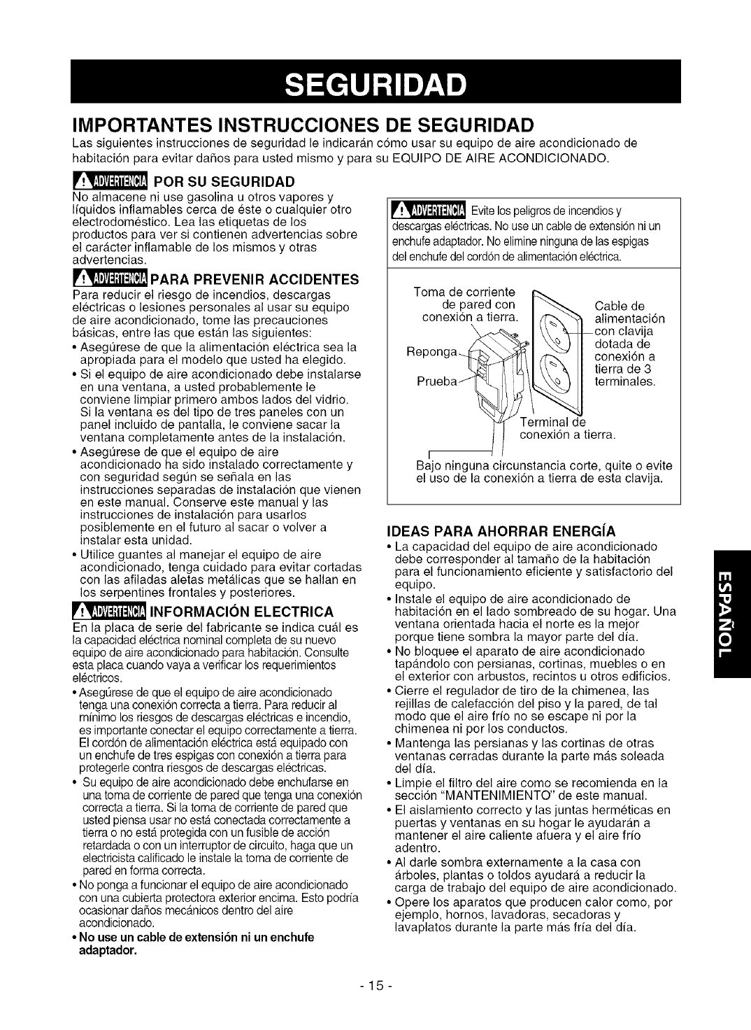
_ Evitelospeligrosde incendiosy
descargaselectricas.No useun cable deextensi6nni un
enchufe adaptador.No elimineningunade lasespigas
del enchufedel cordonde alimentacionelectrica.
Toma de corriente
de pared con
conexion a tierra. Cable de
alimentaci6n
--con clavija
dotada de
conexi6n a
tierra de 3
terminales.
Terminal de
conexi6n a tierra.
r
Bajo ninguna circunstancia corte, quite o evite
el uso de la conexion a tierra de esta clavija.
IDEAS PARA AHORRAR ENERG[A
• La capacidad del equipo de aire acondicionado
debe corresponder al tamaSo de la habitacion
para el funcionamiento eficiente y satisfactorio del
equipo.
• Instale el equipo de aire acondicionado de
habitacion en el lado sombreado de su hogar. Una
ventana orientada hacia el norte es la mejor
porque tiene sombra la mayor parte del dfa.
• No bloquee el aparato de aire acondicionado
tapandolo con persianas, cortinas, muebles o en
el exterior con arbustos, recintos u otros edificios.
• Cierre el regulador de tiro de la chimenea, las
rejillas de calefaccion del piso y la pared, de tal
modo que el aire fifo no se escape ni por la
chimenea ni por los conductos.
• Mantenga las persianas y las cortinas de otras
ventanas cerradas durante la parte mas soleada
del dia.
• Limpie el filtro del aire como se recomienda en la
secci6n "MANTENIMIENTO" de este manual.
• El aislamiento correcto y las juntas hermeticas en
puertas y ventanas en su hogar le ayudaran a
mantener el aire caliente afuera y el aire frfo
adentro.
• AI darle sombra externamente a la casa con
arboles, plantas o toldos ayudara a reducir la
carga de trabajo del equipo de aire acondicionado.
• Opere los aparatos que producen calor como, por
ejemplo, hornos, lavadoras, secadoras y
lavaplatos durante la parte mas frfa del dia.
-15-
RESPETE TODOS LOS CODIGOS Y
REGLAMENTOS.
BAJO NINGUNA ClRCUNSTANCIA CORTE,
QUITE O EVITE EL USO DE LA CONEXION
A TIERRA DE ESTA CLAVIJA.
ESTE APARATO NECESITA SER
CONECTADO A TIERRA.
Se requiere una alimentaci6n electrica CA,
adecuadamente conectada a tierra con un
fusible de 20 A, de 60 Hz y de 250 V.
Se recomienda un fusible de retardo o un
disyuntor de circuito que alimente solamente a
este aparato.
NO USE CABLE ELECTRICO DE
EXTENSION.
MI_TODO RECOMENDADO DE CONEXION A
TIERRA
Por su propia seguridad este aparato debe
conectarse a tierra. Este aparato viene
equipado con un cable de alimentaci6n y una
clavija de tres terminales. Para reducir al
maximo el peligro de choque electrico, el cable
debe estar conectado a una conexi6n de pared
con conexi6n a tierra, y esta conexi6n debe
hacerse de acuerdo con la ultima edici6n del
C6digo Electrico Nacional (ANSI/NFPA 70), asf
como con los c6digos y reglamentos locales. Si
no existe una conexi6n de pared adecuada, el
cliente tiene la responsabilidad y la obligaci6n
de mandar instalar, con un electricista
calificado, una conexi6n de pared adecuada de
tres terminales con conexi6n a tierra.
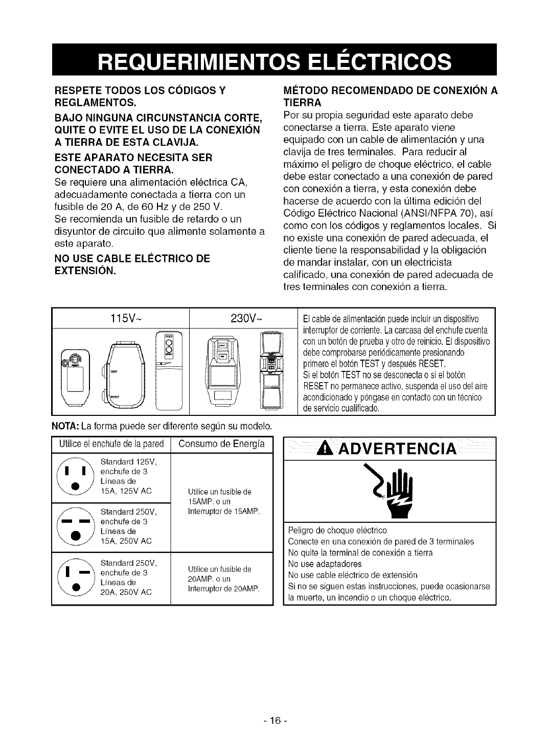
115V~
I I
230V~
r- I
Elcabledealimentaci6npuedeincluirundispositivo
interruptordecorriente.Lacarcasadelenchufecuenta
conunbot6ndepruebay otrodereinicio.Eldispositivo
debecomprobarseperi6dicamentepresionando
primeroelbot6nTESTy despuesRESET.
Sielbot6nTESTnosedesconectaosi elbot6n
RESETnopermaneceactive,suspendaelusodelaire
acondicionadoy p6ngaseencontactoconuntecnico
deserviciocualificado.
NOTA: La forma puede ser diferente segun su modelo.
Utiliceelenchufede lapared Consumo de Energfa
@ tandard 125V,
enchufe de 3
Lfneas de
15A, 125V AC Utilice un fusible de
15AMP. o un
Standard 250V, Interrupter de 15AMP,
enchufe de 3
Lfneas de
15A, 250V AC
Standard 250V,
enchufe de 3 Utilice un fusible de
Lfneas de 20AMP, o un
20A, 250V AC Interrupter de 20AMP.
Peligro de cheque electrico
Conecte en una conexion de pared de 3 terminales
No quite la terminal de conexi6n a tierra
No use adaptadores
No use cable electrico de extensi6n
Si no se siguen estas instrucciones, puede ocasionarse
la muerte, un incendio o un cheque electrico.
-16-
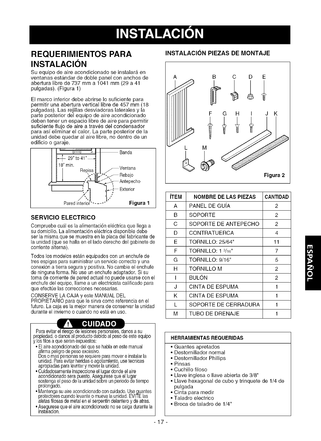
REQUERIMIENTOS PARA
INSTALACION
Su equipo de aire acondicionado se instalara en
ventanas estandar de doble panel con anchos de
abertura libre de 737 mm a 1041 mm (29 a 41
pulgadas). (Figura 1)
El marco inferior debe abrirse Io suficiente para
permitir una abertura vertical libre de 457 mm (18
pulgadas). Las rejillas desviadoras laterales y la
parte posterior del equipo de aire acondicionado
deben tener un espacio libre de aire para permitir
suficiente flujo de aire a traves del condensador
para asf eliminar el calor. La parte posterior de la
unidad debe quedar al aire libre, no dentro de un
edificio o garaje.
Banda
)echo
/
Paredinterior'- .... "Figura 1
SERVIClO ELECTRICO
Compruebe cual es la alimentaci6n electrica que Ilega a
su domicilio. La alimentaci6n electrica disponible debe
ser la misma que se muestra en la placa del fabricante de
la unidad (que se halla en el lade derecho del gabinete de
corriente alterna).
Todos los modelos estan equipados con un enchufe de
tres espigas para suministrar un servicio correcto y una
conexion a tierra segura y positiva. No cambie el enchufe
de ninguna forma. No use un enchufe adaptador. Si su
toma de corriente de pared actual no puede usarse con el
enchufe del equipo, Namea un electricista calificado para
que efectQelas correcciones necesarias.
CONSERVE LA CAJA y este MANUAL DEL
PROPIETARIO para que le sirva come referencia en el
futuro. La caja es la mejor manera de conservar la unidad
durante el invierno o cuando no esta en use.
INSTALACION PIEZAS DE MONTAJE
A B C D E
F G H I J K
Figura 2
iTEM NOMBRE DE LAS PIEZAS CANTIDAD
A PANEL DE GUfA 2
B SOPORTE 2
C SOPORTE DE ANTEPECHO 2
D CONTRATUERCA 4
E TORNILLO: 25/64" 11
F TORNILLO: 1 3/16" 7
G TORNILLO: 9/16" 5
H TORNILLO M 2
I BULON 2
J CINTA DE ESPUMA 1
K CINTA DE ESPUMA 1
L SOPORTE DE CERRADURA 1
M TUBO DE DRENAJE 1
HERRAMIENTAS REQUERIDAS
Paraevitarel riesgode lesionespersonales,danosa su
propiedad,o danesal productodebidoal pesodeesteequipo
y losfilesa queseranexpuestos:
• Elaireacondicionadodelquese hablaenestemanual
afirmapeligrodepesoexcesivo.
Doso maspersonasse requiereparamovere instalarla
unidad.Paraevitarheridasoagotamlentousetecnicas
apropadasparaevntary movera undad.
• Cuidadosamenteinspeccioneel lugardondeelaire
acondicionadosera puesto.Asegureseque ellugar
sostengael pesode la unidadsobreunperiododetiempo
prolongado.
• Mantengasu aireacondicionadoconcuidado.Useguantes
protectorescuandolevanteo muevala unidad.EVITElas
aletasfilosasde metalen elserpentindelanteroy deatras.
•Aseguresequeel aireacondicionadonose caigadurantela
instalacion.
-17-
•Guantes apretados
•DestorniNador normal
•DestornNlador Phillips
•Pinsas
• Cuchillo filoso
• Llave inglesa o Ilave abierta de 3/8"
• Llave hexagonal de cube y trinquete de 1/4 de
pulgada
• Cinta para medir
• Taladro electrico
• Broca de taladro de 1/4"
INSTALACION
Escojaunlugar que le permitaIlevarel aire frio al Areaque
desea.Lasventanasque se usenpara lainstalaci6ndeben
tener la resistenciasuficienteparasoportarel pesodelequipo
de aireacondicionado.Unabuenainstalaci6ncon atenci6n
especiala la correctaposici6nde la unidaddisminuirala
probabilidadde quesea necesarioefectuarreparaciones.
Cuandose deseaenfriar mas de una habitaci6n,la
instalaci6nes muyimportantesi el aireacondicionadoest,.
bloquedopor un marcode lacontraventanavea el paso 16en
la pagina8 antesde comenzarla instalacion.Para enfriarsus
habitaciones,el airefrio debe desplazarsedesde el equipode
aire acondicionadoen una trayectoriarecta.
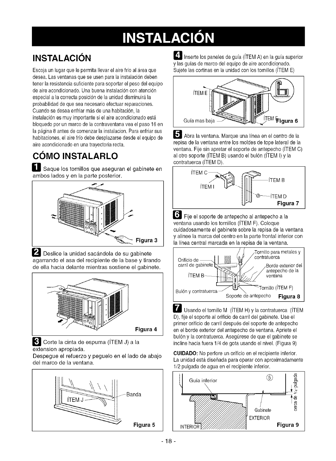
COMO INSTALARLO
H Saque los tornillos que aseguran el gabinete en
ambos lados yen la parte posterior.
Figura 3
_ Deslice la unidad sacandola de su gabinete
agarrando el asa del recipiente de la base y tirando
de ella hacia delante mientras sostiene el gabinete.
Figura 4
_l Corte la cinta de espuma (iTEM J) a la
extension apropiada.
Despegue el refuerzo y peguelo en el lado de abajo
del marco de la ventana.
JBanda
Figura 5
D Inserte los panelesde gufa (iTEM A) en la guiasuperior
y las guias demarco del equipode aire acondicionado.
Sujete las cortinasen la unidadcon los tornillos (iTEME)
iTEME
Gufa mas baja E_igura 6
_/'_ Abra la ventana. Marque una Ifnea en el centro de la
repisa de la ventana entre los moldes de tope lateralde la
ventana. Fije sin apretar el soporte de antepecho (iTEM C)
al otro soporte (iTEM B) usando el bul6n (fTEM I) y la
contratuerca (iTEM D).
iTEM I
"'@_iTEM D
Figura 7
r"_ Fije el soporte de antepecho al antepecho a la
ventana usando los tornillos (fTEM F). Coloque
cuidadosamente el gabinete sobre la repisa de la ventana
y alinee la marca del centre en la parte frontal inferior con
la linea central marcada en la repisa de la ventana.
parametaiesy
Orificiode-- exteriordel
ventana
(iTEMF)
Butony contratuerca Soportedeantepecho Figura 8
W Usando el tornillo M (iTEM H) y la contratuerca (iTEM
D), fije el soporte al orificio de carril del gabinete. Use el
primer orificiode carril despues del soporte de antepecho
en el borde exterior del antepechode ventana. Apriete el
bubn y la contratuerca. AsegtJreeede que el gabinete se
incline haciafuera 1/4de gota usando el nivel. (Figura9)
CUIDADO: No perfore un orificioen el recipiente inferior.
La unidad est,. disei_adapara operarcon aproximadamente
1/2pulgada de agua en el recipiente inferior.
Gufa inferior _
INTERIOR
Gabinete o_
EXTERIOR
Figura 9
-18-
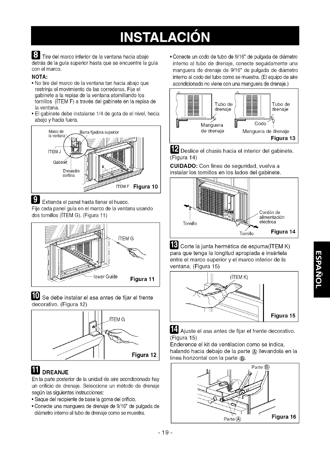
_J_ Tire del marco inferior de la ventana hacia abajo
detras de la gufa superior hasta que se encuentre la gufa
con el marco.
NOTA:
•No tire del marco de la ventana tan hacia abajo que
restrinja el movimiento de las correderas. Fije el
gabinete a la repisa de la ventana atornillando los
tornillos (ITEM F) a traves del gabinete en la repisa de
la ventana.
• El gabinete debe instalarse 1/4 de gota de el nivel, hecia
abajo y hacia fuera.
Marco de. _Barra fijadora superior
la ventanai,X_ _.._
_ [TEMF Figura 10
_ Extienda el panel hasta Ilenar el hueco.
Fije cada panel gufa en el marco de la ventana usando
dos tornillos (ITEM G). (Figura 11)
fTEM G
lowerGuide Figura 11
_1"i] Se debe instalar el asa antes de fijar el frente
decorativo. (Figura 12)
fTEMG
Figura 12
E_IDREANJE
En la parte posteriorde la unidadde aire acondicionadohay
un orificio de drenaje. Seleccione un metodo de drenaje
segL_nlassiguientesinstrucciones:
• Saquedel recipientede base lagoma del orificio.
• Conecte una manguerade drenajede 9/16" de pulgada de
diametrointernoal tubode drenajecomo se muestra.
• Conecte un codo de tubode 9/16" de pulgadade diametro
interno al tubo de drenaje, conecte seguidamente una
manguera de drenaje de 9/16" de pulgada de diametro
interno alcodo del tubo como se muestra.(El equipode aire
acondicionadonovienecon una manguerade drenaje.)
(_, jq
)u o eL Tu o e
renaje drenaje
Manguera _j
de drenaje Manguera de drenaje
Figura 13
_"_ Deslice el chasis hacia el interior del gabinete.
(Figura 14)
CUlDADO: Con fines de seguridad, vuelva a
instalar los tornillos en los lados del gabinete.
alirnentacion
Tornillo electrica
Tornillo Figura 14
_"lJ Corte la junta hermetica de espuma(fTEM K)
para que tenga la Iongitud apropiada e insertela
entre el marco superior y el marco inferior de la
ventana. (Figura 15)
Figura 15
_1] Ajuste el asa antes de fijar el frente decorativo.
(Figura 15)
Enderence el kit de ventilacion come se indica,
halando hacia debajo de la parte _) Ilevandola en la
linea horizontal con la parte ®.
Parte (_
Parte@ Figura 16
-19-
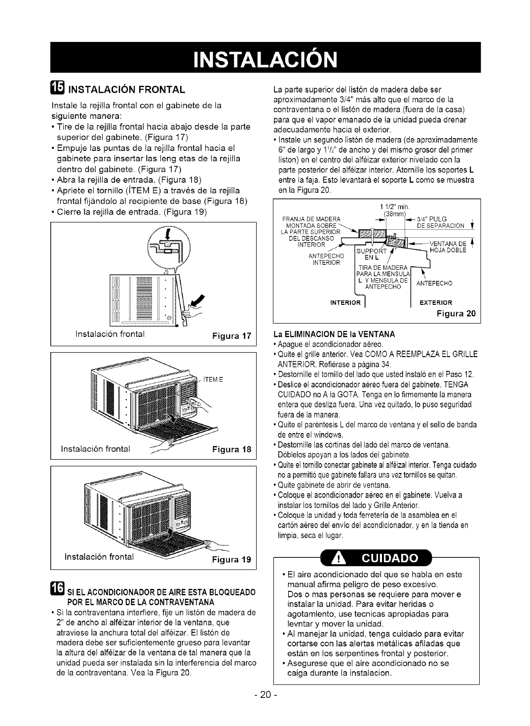
[] INSTALACION FRONTAL
Instale la rejilla frontal con el gabinete de la
siguiente manera:
• Tire de la rejilla frontal hacia abajo desde la parte
superior del gabinete. (Figura 17)
• Empuje las puntas de la rejilla frontal hacia el
gabinete para insertar las leng etas de la rejilla
dentro del gabinete. (Figura 17)
• Abra la rejilla de entrada. (Figura 18)
• Apriete el tornillo (ITEM E) a traves de la rejilla
frontal fijandolo al recipiente de base (Figura 18)
• Cierre la rejilla de entrada. (Figura 19)
Instalacion frontal Figura 17
Instalaci6n frontal Figura 18
Ir*!_ [*_IJlJ7-'IJX*]
Instalacion frontal Figura 19
]SI EL ACONDIClONADOR DE AIRE ESTA BLOQUEADO
POR EL MARCO DE LA CONTRAVENTANA
•Si la contraventana interfiere, fije un liston de madera de
2" de ancho al alfeizar interior de la ventana, que
atraviese la anchura total del alfeizar. El liston de
madera debe ser suficientemente grueso para levantar
la altura del alfeizar de la ventana de tal manera que la
unidad pueda ser instalada sin la interferencia dei marco
de la contraventana. Vea Ia Figura 20.
La parte superior del liston de madera debe ser
aproximadamente 3/4" mas alto que el marco de la
contraventana o el list6n de madera (fuera de la casa)
para que el vapor emanado de Ia unidad pueda drenar
adecuadamente hacia eI exterior.
•Instale un segundo Iist6n de madera (de aproximadamente
6" de largo y 172' de ancho y det mismo grosor del primer
liston) en el centro det alfeizar exterior nivetado con ta
parte posterior det alfeizar interior. Atomille los soportes L
entre Ia faja. Esto tevantara et soporte L como se muestra
en la Figura 20.
1 112"min.
38mm)
FRANJADEMADERA ''1 I-.,,_34" PULG
MONTADA SOBRE / DESEPARAC,ON*
LAPARTESUPERIO
DELDESCANSO
INTERIOR -"t___IENTANA DE J"
HOJADOBLE
ANTEPECHO
INTERIOR
ANTEPECHO
ERIOR
Figura 20
La ELIMINACION DE la VENTANA
•Apague el acondicionador aereo.
• Quite el grille anterior. Yea COMO A REEMPLAZA EL GRILLE
ANTERIOR. Refierase a pagina 34.
• Destornille el tornilIo del tado que usted instalo en el Paso 12.
• Deslice el acondicionador aereo fuera del gabinete. TENGA
CUIDADO no A la GOTA. Tenga en Io firmemente la manera
entera que desliza fuera. Una vez quitado, Io puso seguridad
fuera de ta manera.
• Quite el parentesis Ldel marco de ventana y el sello de banda
de entre el windows.
• Destomille las cortinas det lado del marco de ventana.
D6blelos apoyan a los lados del gabinete.
• Quite el tornittoconectar gabinete al alfeizal interior.Tenga cuidado
no a permitio que gabinete fallara una vez tomillos se quitan.
• Quite gabinete de abrir de ventana.
• Coloque el acondicionador aereo en el gabinete. Vuelva a
instalar los tomillos del lado y Grille Anterior.
• Coloque la unidad y toda ferreteria de la asamblea en el
carton aereo del envio del acondicionador, yen la tienda en
limpia, seca el lugar.
• El aire acondicionado del que se habla en este
manual afirma peligro de peso excesivo.
Dos o mas personas se requiere para mover e
instalar la unidad. Para evitar heridas o
agotamlento, use tecnicas apropiadas para
levntar y mover la unidad.
• AI manejar la unidad, tenga cuidado para evitar
cortarse con las alertas met&licas afiladas que
est&n en los serpentines frontal y posterior.
• Asegurese que el aire acondicionado no se
caiga durante la instalacion.
- 20 -
COMO Y POR QUI
Su equipo de aire acondicionado de habitaci6n
brinda las siguientes funciones para hacer que la
vida en climas c_.lidos sea mas confortable:
• Enfrfa y hace circular el aire por la habitaci6n
• Disminuye la humedad eliminando la humedad
excesiva.
• Filtra el polvo, el sucio y algunas impurezas
transportadas en el aire del clima veraniego.
El equipo de aire acondicionado realiza estas
funciones haciendo pasar el aire del medio
ambiente a traves de un filtro que atrapa las
partfculas de polvo y sucio. El aire pasa entonces
per un serpentin de enfriamiento que refrigera el
aire y elimina el exceso de humedad. El mismo aire
regresa entonces al enfriador, secador y limpiador
del aire del ambiente. La humedad extraida del aire
ambiente es Ilevada al exterior y evaporada.
Su aire acondicionado esta disefiado para operar y
suministrar una enorme potencia de enfriamiento.
SONIDOS NORMALES Figura 21
Ademas de los sonidos regulares del motor del
ventilador y el compresor que salen de su equipo
de aire acondicionado, usted escuchara de vez en
cuando un sonido metalico. Este sonido es
producido per la humedad que es recogida del aire
en el ambiente yes lanzada contra el ventilador del
equipo de aire acondicionado. Esto es algo normal
que no debe ser motive de preocupaci6n. De igual
modo, no se alarme si usted escucha un ligero
sonido de silbido o borboteo proveniente de su
equipo de aire acondicionado despues que Io
apaga. Estos son ruidos normales del refrigerante.
CAPACIDAD Y TIEMPO DE
FUNCIONAMIENTO
AI decidir cual debe ser la comodidad deseada para el
area que usted quiere enfriar, es importante
determinar el tamaflo correcto de la unidad. El tamafio
adecuado es determinado por el nL_merode metros
cuadrados que tiene el &rea que se desea enfriar, asf
como per la temperatura interior y exterior y por la
humedad.
Siempre que la carga termica del ventilador este per
encima de Io normal, el equipo de aire acondicionado
debe funcionar m&s tiempo para mantener la
temperatura deseada que usted ha seleccionado. Bajo
condiciones de una carga termica muy pesada, puede
ser necesario que el equipo de aire acondicionado
funcione constantemente para mantener la
temperatura deseada.
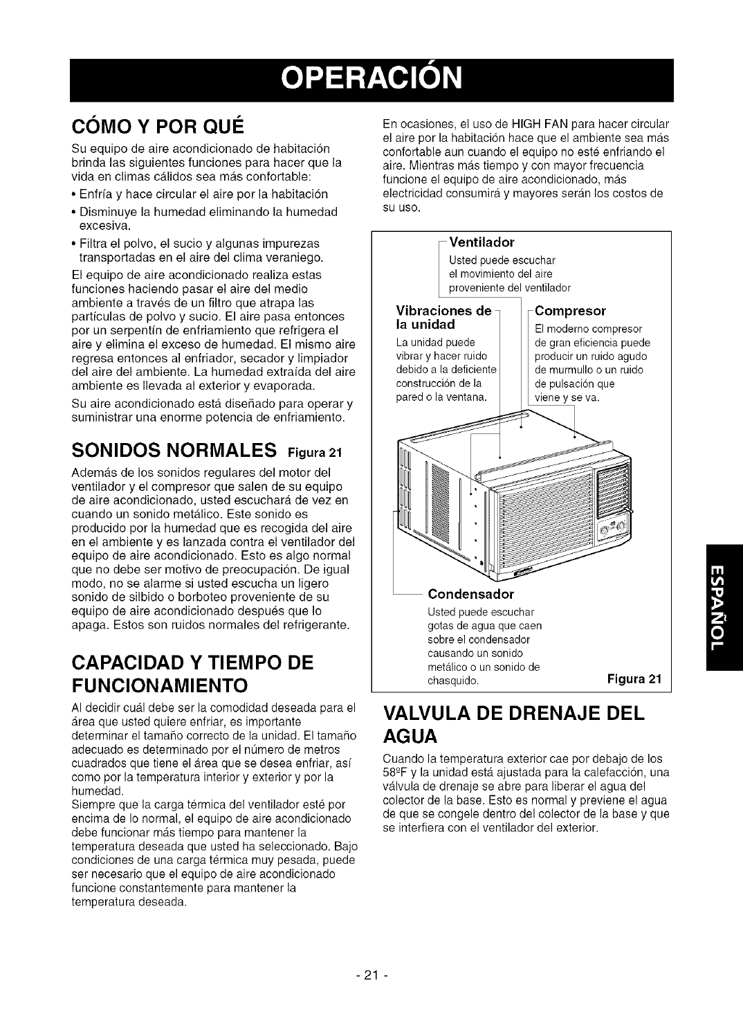
En ocasiones, el uso de HIGH FAN para hacer circular
el aire per la habitacion hace que el ambiente sea mas
confortable aun cuando el equipo no este enfriando el
aire. Mientras mas tiempo y con mayor frecuencia
funcione el equipo de aire acondicionado, mas
electricidad consumira y mayores seran los costos de
SU use.
Ventilador
Ustedpuedeescuchar
el movimientodel aire
provenientedel ventilador
Vibraciones de
la unidad
Launidadpuede
vibrary hacerruido
debidoa la deficiente
construccionde la
pared o laventana.
Compresor
El moderno compresor
de gran eficiencia puede
producir un ruido agudo
de murmullo o un ruido
de pulsaci6n que
viene y se va.
Condensador
Usted puede escuchar
gotas de agua que caen
sobre el condensador
causando un sonido
metalico o un sonido de
chasquido. Figura 21
VALVULA DE DRENAJE DEL
AGUA
Cuando la temperatura exterior cae per debajo de los
58-°Fy la unidad esta ajustada para la calefacci6n, una
valvula de drenaje se abre para liberar el agua del
colector de la base. Esto es normal y previene el agua
de que se congele dentro del colector de la base y que
se interfiera con el ventilador del exterior.
-21 -
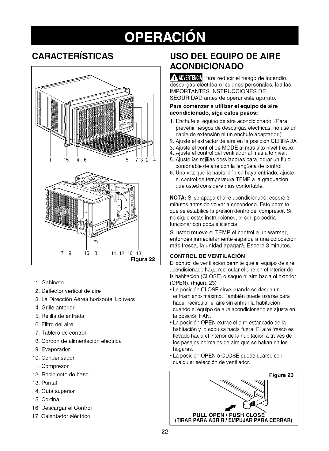
CARACTER|STICAS
15 4 6 5 73 214
17 9 16 8 11 12 10 13
Figura 22
1. Gabinete
2. Deflector vertical de aire
3. La Direcci6n Aerea horizontal Louvers
4. Grille anterior
5. Rejilla de entrada
6. Filtro del aire
7. Tablero de control
8. Cord6n de alimentacion electrica
9. Evaporador
10. Condensador
11. Compresor
12. Recipiente de base
13. Puntal
14. Gu[a superior
15. Cortina
16. Descargar el Control
17. Calentador electrico
USO DEL EQUIPO DE AIRE
ACONDICIONADO
_Para reducir el riesgo de incendio,
descargas electrica o lesiones personales, lea las
IMPORTANTES INSTRUCCIONES DE
SEGURIDAD antes de operar este aparato.
Para comenzar a utilizar el equipo de aire
acondicionado, eiga estos pasos:
1. Enchufe el equipo de aire acondicionado. (Para
prevenir riesgos de descargas electricas, no use un
cable de extension ni un enchufe adaptador.)
2. Ajuste el extractor de aire en la posicion CERRADA
3. Ajuste el control de MODE al mas alto nivel fresco.
4. Ajuste el control del ventilador al ma.salto nivel.
5. Ajuste las rejillas desviadoras para Iograr un flujo
confortable de aire con la lengeeta de control.
6. Una vez que la habitacion se haya enfriado, ajuste
el control de temperatura TEMP a la graduacion
que usted considere mdtsconfortable.
NOTA: Si se apaga el aire acondicionado, espere 3
minutos antes de volver a encenderlo. Esto permite
que se estabilice la presi6n dentro del compresor. Si
no sigue estas instrucciones, el equipo podr[a
funcionar con poca eficiencia.
Si usted mueve el TEMP el control a un warmer,
entonces inmediatamente espalda a una colocaci6n
mas fresca, la unidad apagar& Espere 3 minutos.
CONTROL DE VENTILACION
El control de ventilacion permite que el equipo de aire
acondicionado haga recircular el aire en el interior de
la habitacion (CLOSE) o saque el aire hacia el exterior
(OPEN). (Figura 23)
• La posici6n CLOSE sirve cuando se desea un
enfriamiento maximo. Tambien puede usarse para
hacer recircular el aire sin enfriar la habitaci6n
cuando el equipo de aire acondicionado se ajusta en
la posicion FAN.
• La posici6n OPEN extrae el aire estancado de la
habitacion y Io expulsa hacia fuera. El aire fresco es
Ilevado hacia el interior de la habitaci6n a traves de
los pasajes normales de aire que se hallan en los
hogares.
• La posici6n OPEN o CLOSE puede usarse con
cualquier selecci6n de ventilador.
Figura 23
PULL
(TIRAR PARA ABRIR /EMPUJAR PARA CERRAR)
- 22 -
CARACTERiSTICAS DEL EQUIPO DE AIRE ACONDIClONADO
Los controles que se explican en este manual son representativos de muchos modelos disponibles a la
venta en el mercado. Su modelo puede tener un aspecto ligeramente diferente.
OFF D ON
Auto Swing
OFF
FAN FAN
ONLY ONLY
HIGH HIGH
HEAT COOL
TEMP MODE
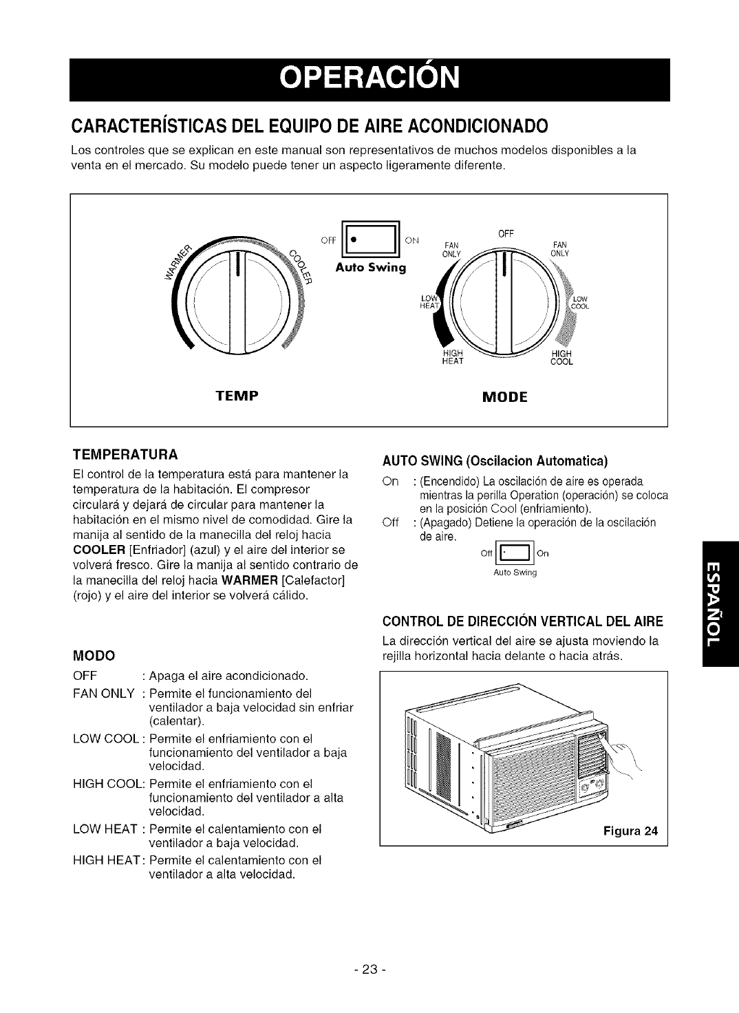
TEMPERATURA
El control de la temperatura esta para mantener la
temperatura de la habitacion. El compresor
circulara y dejara de circular para mantener la
habitaci6n en el mismo nivel de comodidad. Gire la
manija al sentido de la manecilla del reloj hacia
COOLER [Enfriador] (azul) y el aire del interior se
volvera fresco. Gire la manija al sentido contrario de
la manecilla del reloj hacia WARMER [Calefactor]
(rojo) y el aire del interior se volver_, calido.
MODO
OFF
FAN ONLY :
LOW COOL :
HIGH COOL:
LOW HEAT :
HIGH HEAT:
: Apaga el aire acondicionado.
Permite el funcionamiento del
ventilador a baja velocidad sin enfriar
(calentar).
Permite el enfriamiento con el
funcionamiento del ventilador a baja
velocidad.
Permite el enfriamiento con el
funcionamiento del ventilador a alta
velocidad.
Permite el calentamiento con el
ventilador a baja velocidad.
Permite el calentamiento con el
ventilador a alta velocidad.
AUTO SWING (Oscilacion Automatica)
On : (Encendido) La oscilaci6n de aire es operada
rnientras la perilla Operation (operacion) se coloca
en la posici6n Cool (enfriamiento).
Off : (Apagado) Detiene la operaci6n de la oscilaci6n
de aire.
Off [_ On
Auto Swing
CONTROL DE DIRECCION VERTICAL DEL AIRE
La direcci6n vertical del aire se ajusta moviendo la
rejilla horizontal hacia delante o hacia atras.
Figura 24
-23 -
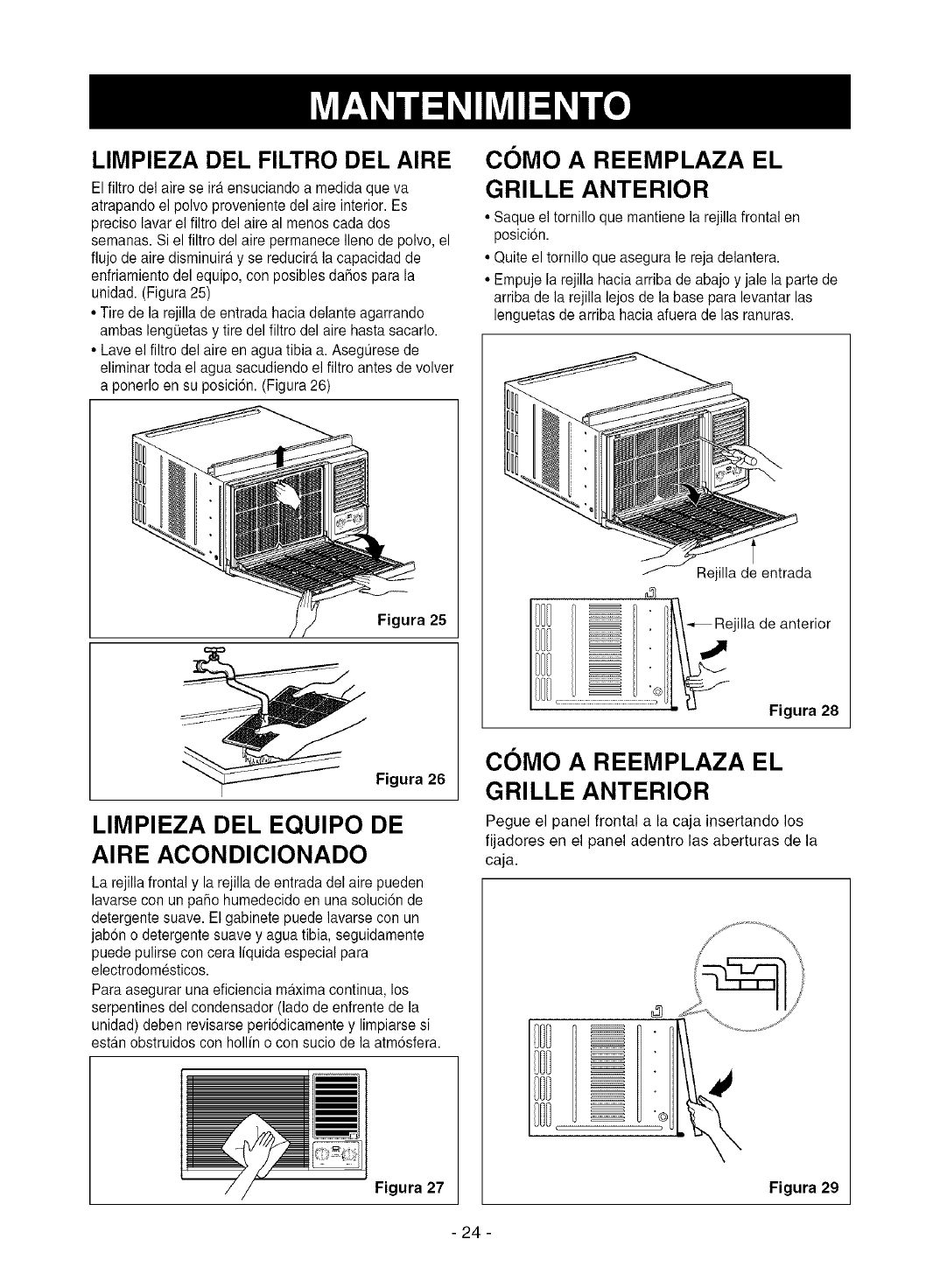
LIMPIEZA DEL FILTRO DEL AIRE
El filtro del aire se ira ensuciando a medida que va
atrapando el polvo proveniente del aire interior. Es
preciso lavar el filtro del aire al menos cada dos
semanas. Si el filtro del aire permanece Ileno de polvo, el
fiujo de aire disminuira y se reducir_,la capacidad de
enfriamiento del equipo, con posibles daflos para la
unidad. (Figura 25)
• Tire de la rejilla de entrada hacia delante agarrando
ambas lengQetasy tire del filtro del aire hasta sacarlo.
• Lave el filtro del aire en agua tibia a. Asegurese de
eliminar toda el agua sacudiendo el filtro antes de volver
a ponerlo en su posici6n. (Figura 26)
Figura 25
Figura 26
LIMPIEZA DEL EQUIPO DE
AIRE ACONDICIONADO
La rejilla frontal y la rejilla de entrada del aire pueden
lavarse con un patio humedecido en una soluci6n de
detergente suave. El gabinete puede lavarse con un
jabon o detergente suave y agua tibia, seguidamente
puede pulirse con cera Ifquida especial para
electrodomesticos.
Para asegurar una eficiencia maxima continua, los
serpentines del condensador (lade de enfrente de la
unidad) deben revisarse periodicamente y limpiarse si
estan obstruidos con hollin o con sucio de la atm6sfera.
Figura 27
COMO A REEMPLAZA EL
GRILLE ANTERIOR
• Saque el tomillo que mantiene la rejilla frontal en
posicion.
• Quite el tornillo que asegura le reja delantera.
• Empuje la rejilla hacia arriba de abajo y jale la parte de
arriba de la rejilla lejos de la base para levantar las
lenguetas de arriba hacia afuera de las ranuras.
Rejilla de entrada
. _ Rejilla de anterior
Figura 28
COMO A REEMPLAZA EL
GRILLE ANTERIOR
Pegue el panel frontal a la caja insertando los
fijadores en el panel adentro las aberturas de la
caja.
- 24 -
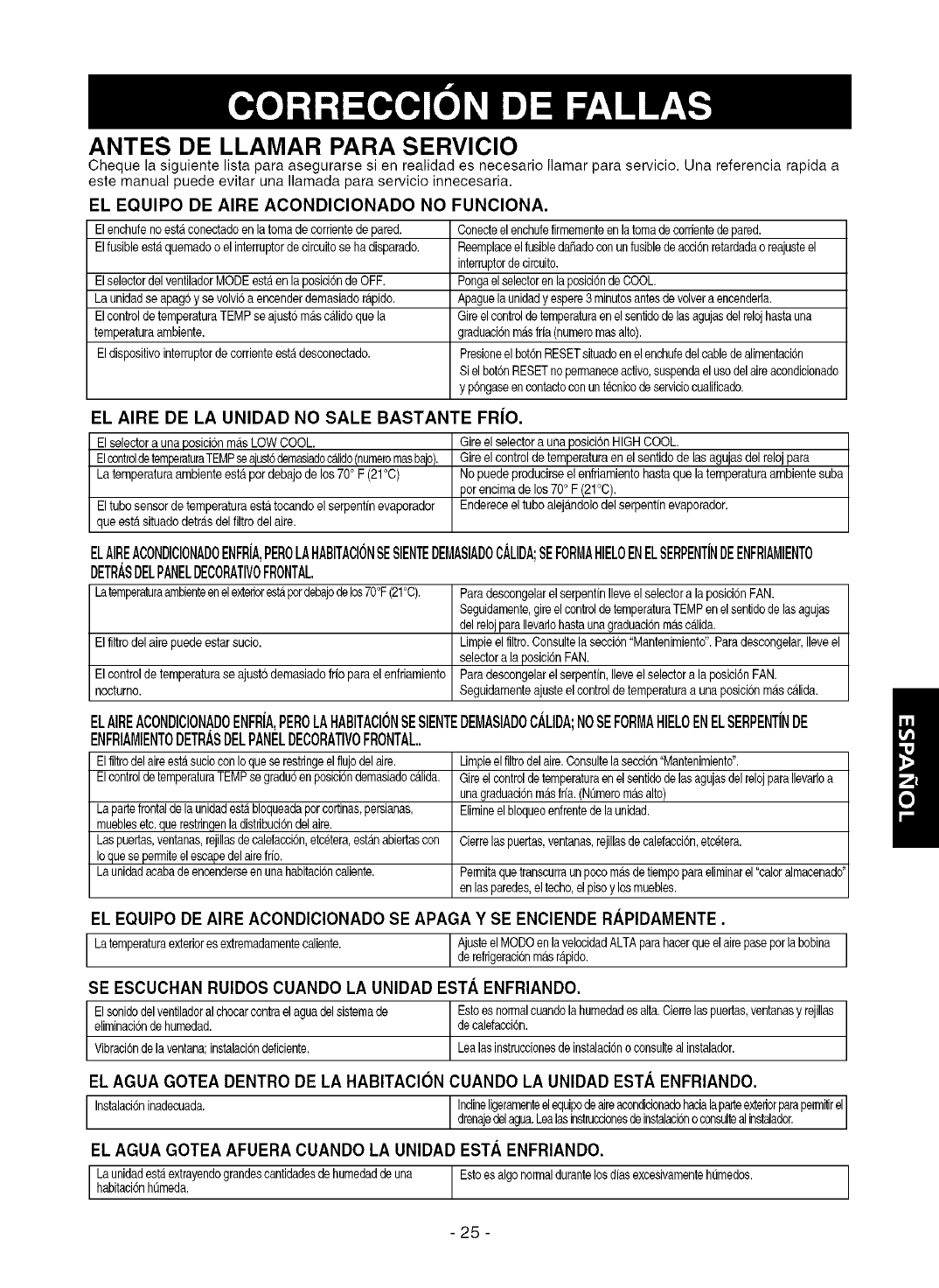
ANTES DE LLAMAR PARA SERVICIO
Cheque la siguiente lista para asegurarse si en realidad es necesario Ilamar para servicio. Una referencia rapida a
este manual puede evitar una Ilamada para servicio innecesaria.
EL EQUlPO DE AIRE ACONDIOIONADO NO FUNClONA.
Elenchufeno estaconectadoen latomadecorrientede pared. Conecteelenchufefirmementeenlatomade corrientedepared.
Elfusibleestaquemadoo el interruptordecircuitoseha disparado. ReemplaceelfusibledaSadoconunfusiblede acoi6nretardadao reajusteel
interruptorde circuito.
ElselectordelventiladorMODEestaen la posici6nde OFF. Pongaelselectorenlaposici6ndeCOOL.
La unidadseapag6y sevolvi6a encenderdemasiador_pido. Apaguela unidady espere3 minutosantesdevolvera encenderla.
Elcontrolde temperaturaTEMPseajust6m&scalidoquela Gireelcontrolde temperaturaenelsentidode lasagujasdelrelojhastauna
temperaturaambiente, graduaci6nm_sfria (numeromasalto).
Eldispositivointerruptordecorrienteestadesconectado. Presioneel bot6nRESETsituadoenel enchufedelcablede alimentaci6n
Sielbot6nRESETnopemlaneceactivo,suspendaelusedelaireacondicionado
y p6ngaseencontactoconun tecnicode serviciocualificado.
EL AIRE DE LA UNIDAD NO SALE BASTANTE FRIO.
Elselectora unaposici6nma.sLOW COOL.
ElcontroldetemperaturaTEMPseajusbdernasiadocalido(nurneromasbale).
La temperaturaambienteestapordebajode los70° F (21°C)
Gireelselectora unaposici6nHIGHCOOL.
Gireelcontrolde temperaturaen el sentidode las agujasdelreloj para
Nopuedeproducirseel enfriamientohastaque latemperaturaambientesuba
por eneimade los 70o F(21°C).
Eltubosensorde temperaturaestatocandoel serpentfnevaporador Endereceeltubo aleja.ndolodelserpentfnevaporador.
queestasituadodetra.sdelfiltrodelaire.
ELAIREACONDIClONADOENFRIA,PEROLAHABITACl6NSESIENTEDEMASIADOOALIDA;SEFORMAHIELOENELSERPENTINDEENFRIAMIENTO
DETR._SDELPANELDECORATIMOFRONTAL.
°lLathe enelexted°restAp°rdebaj°deI°s70°F(21°C)' / ParadescongelarelserpentinIleveel selectora laposicionFAN.
Seguidamente,gireelcontroldetemperaturaTEMPenelsentidode lasagujas
delrelojparaIlevariohastaunagraduaci6nmascalida.
I EIfiltrodelairepuedeestarsucio. Limpieelfiltro.Consultelaseccion"Mantenimiento".Paradescongelar,Ileveel
selectora laposici6nFAN.
I Elco_ frio parael enfriamiento Paradescongelarelserpentin,Ileveelselectora la posici6nFAN.
I nocturno. Seguidamenteajusteelcontrolde temperaturaa unaposici6nmascalida.
ELAIREACONDICIONADOENFRiA,PEROLAHABITACIONSESIENTEDEMASIADOCALIDA;NOSEFORMAHIELOENELSERPENTiNDE
ENFRIAMIENTODETRASDELPANELDECORATIVOFRONTAL,.
Elfiltrodelaireest,1sucioconIoqueserestringeelflujodelaire. Limpieelfiltrodelaire.Consultelasecoi6n"Mantenimiento".
Elcontrolde temperaturaTEMPsegradu6en posici6ndemasiadoc_ilida. GireelcontroldetemperaturaenelsentidodelasagujasdelrelojparaIlevarloa
unagraduaci6nm_sfde.(N0meromasalto)
Elimineelbloqueoenfrentede launidad.
Lapartefrontaldela unidadest,1bloqueadaporcortinas,persianas,
mueblesetc.querestringenladistribuci6ndelaire.
Laspuertas,ventanas,rejillasdecalefacoi6n,etcetera,estAnabiertascon
Ioquesepermiteelescapedelairefrb.
Launidadacabade encenderseenunahabitaci6ncaliente.
Cierrelaspuertas,ventanas,rejillasde calefacci6n,etcetera.
PermitaquetranscurraunpocomAsdetiempoparaeliminarel"caloralmacenado"
enlas paredes,eltecho,elpisoy losmuebles.
EL EQUIPO DE AIRE AOONDICIONADO SE APAGA Y SE ENClENDE RAPIDAMENTE.
Latemperaturaexterioresextremadamentecaliente. AjusteelMODOenlavelocidadALTAparahacerqueelairepaseporlabobina
derefdgeraci6nm&sr_ipido.
SE ESCUOHAN RUlDOS CUANDO LA UNIDAD ESTA ENFRIANDO.
Elsonidodelventiladoralchocarcontrael aguadelsistemade Estoesnormalcuandolahumedadesalta.Cierrelaspuertas,ventanasy rejillas
eliminaci6nde humedad, decalefacci6n.
Vibraci6nde laventana;instalaci6ndeficiente. Lealasinstruccionesde instalaci6no consulteal instalador.
EL AGUA GOTEA DENTRO DE LA HABITACION CUANDO LA UNIDAD ESTA ENFRIANDO.
Instalaci6ninadecuada. Indineligeramenteelequipodeaireacondicionadohacialaparteexteriorparape_ilir el
drenajede agua.Leaas nstruccionesde nstaac6no consutea nstalader.
EL AGUA GOTEA AFUERA CUANDO LA UNIDAD ESTA ENFRIANDO.
Launidadestaextrayendograndescantidadesdehumedadde una Estoesalgo normaldurantelosdfasexcesivamentehtJmedos.
habitaci6nhQmeda.
-25 -
i 26 i
Master Protection Agreements
Congratulations on making a smart purchase.
Your new Kenmore ® product is designed and
manufactured for years of dependable operation.
But like all products, it may require preventive
maintenance or repair from time to time.
That's when having a Master Protection Agreement
can save you money and aggravation.
Purchase a Master Protection Agreement now and
protect yourself from unexpected hassle and
expense.
The Master Protection Agreement also helps extend
the life of your new product. Here's what's included
in the Agreement:
[] Expert service by our 12,000 professional
repair specialists
[] Unlimited service and no charge for parts and
labor on all covered repairs
[] "No-lemon" guarantee - replacement of your
covered product if four or more product failures
occur within twelve months
]Product replacement if your covered product
can't be fixed
[] Annual Preventive Maintenance Check at your
request - no extra charge
[] Fast help by phone - phone support from a
Sears technician on products requiring in-home
repair, plus convenient repair scheduling
[] Power surge protection against electrical
damage due to power fluctuations
[] Rental reimbursement if repair of your covered
product takes longer than promised
Once you purchase the Agreement, a simple phone
call is all that it takes for you to schedule service.
You can call anytime day or night, or schedule a
service appointment online.
Sears has over 12,000 professional repair
specialists, who have access to over 4.5 million
quality parts and accessories. That's the kind of
professionalism you can count on to help prolong
the life of your new purchase for years to come.
Purchase your Master Protection Agreement today!
Some limitations and exclusions apply.
For prices and additional information call
1-800-827-6655.
Sears Installation Service
For Sears professional installation of home
appliances, garage door openers, water
heaters, and other major home items, in the
U.S.A. call 1-800-4-MY-HOME _
Acuerdos de Proteccibn Especializada
iEnhorabuena! Ha realizado una compra inteligente,
Su nuevo aparato Kenmore® esta. diseflado y fabricado
para ofrecerle afios de buen funcionamiento.
Sin embargo, al igual que todos los productos, puede
precisar un manteeimiento preveetivo o incluso alguna
reparaci6n de vez en cuando. En esas ocasiones, un
Master Protection Agreement puede ayudarle a ahorrar
dinero e incoevenientes.
Adquiera un Master Protection Agreement ahora, y
protejase a s[ mismo de molestias y gastos inesperados.
El Master Protection Agreement le ayudara, tambien a
prolongar la vida de su nuevo aparato. Los siguientes
servicios esta.n incluidos:
[] Servicio experto por parte de cualquiera de
nuestros 12.000 tecnicos profesionales especialistas
de Sears.
[] Prestacion de servicios sin limitaciones y sin
cargarle las piezas o la mano de obra en todas las
reparaciones cubiertas pot el acuerdo.
[] Garantia seria de sustitucibn de las piezas del
producto cubierto pot el acuerdo, si cuatro o mas
piezas se mostrasen defectuosas en un periodo de
doce meses.
[] Sustitucion del producto por otro nuevo, si el
defectuoso no pudiese repararse.
[] Control de mantenimiento anual preventivo,
siempre que Io desee y sin gasto adicional alguno.
[] Asistencia telefbnica inmediata de un tecnico
especialista en productos que ban de ser reparados a
domicilio, ademas de una programaciSn adecuada de
la reparaciSn.
[] Proteccibn contra subidas de tensi6n que
provoquen daflos electricos debidos a las
fluctuaciones en el suministro.
[] Reintegro del alquiler si la reparacion del producto
Ileva mas tiempo del promtetido
Una vez que haya adquirido el Agreement, no necesitarA
masque una simple Ilamada para solicitar el servicio de
su aparato. Ademas, podra hacerlo en cualquier momento
del dia o de la noche, o solicitar una cita para prestaci6n
de servicios online.
Sears cuenta con mas de 12.000 tecnicos profesionales
especialistas en reparaciones, con acceso a mas de 4,5
millones de piezas de sustitucion y accesorios de calidad.
€:ste sera el tipo de profesionalidad y servicio con el que
podrA contar para proloegar la vida de su nuevo producto
por muchos afios, iAdquiera boy mismo su Master
Protection Agreement!
Se aplicaran algunas limitaciones y
restricciones.
Si desea hacer alguna consulta sobre los
precios u otra informacion adicional, le rogamos
Ilame al telefono 1-800-827-6655.
Servicios de Instalacibn Sears
Para solicitar servicios de instalaciSn profesionales
de Sears de electrodomesticos, mandos de apertura
de puertas de garajes, calentadores de agua y otros
aparatos en los Estados Unidos, puede Ilamar a
1-800-4-MY-HOME ®
-27 -

Your Home
For repair- in your home-of all major brand appliances,
lawn and garden equipment, or heating and cooling systems,
no matter who made it, no matter who sold it!
For,the replacement parts accessories and
owner s manuals that you need to do-it-yourself.
For Sears professional installation of home appliances
and items like garage door openers and water heaters.
1-800-4-MY-HOME ® (1-800-469-4663)
Call anytime, day or night (U.S.A. and Canada)
www.sears.com www.sears.ca
Our Home
For repair of carry-in items like vacuums, lawn equipment,
and electronics, call or go on-line for the location of your nearest
Sears Parts & Repair Center.
1-800-488-1222
Call anytime, day or night (U.S.A. only)
, w.sears.oom
To purchase a protection agreement(U.S.A.)
or maintenance agreement(Canada)on a product serviced by Sears:
1-800-827-6655 (U.S.A.) 1-800-361-6665 (Canada)
Pard pedir servicio de reparaciCn Au Canada pour service en fran£_ais:
a domicilio, y pard ordenar piezas: 1-800-LE-FOYER Mc
1-888-SU-HOGAR SM 1 800 533 6937
( - _ _ )
(1-888-784-6427) www.sears.ca
TM SM
® Registered Trademark /Trademark /Service Mark of Sears, Roebuck and Co.
TM SM
® Mama Registrada /Marca de Fdtbrica /Mama de Servicio de Sears, Roebuck and Co.
MD
MCMarque de commerce /Marque d@osee de Sears, Roebuck and Co. ® Sears, Roebuckand Co.
Part No.: 3828A20307D
